WO2016006279A1 - 車両用空調装置 - Google Patents
車両用空調装置 Download PDFInfo
- Publication number
- WO2016006279A1 WO2016006279A1 PCT/JP2015/057793 JP2015057793W WO2016006279A1 WO 2016006279 A1 WO2016006279 A1 WO 2016006279A1 JP 2015057793 W JP2015057793 W JP 2015057793W WO 2016006279 A1 WO2016006279 A1 WO 2016006279A1
- Authority
- WO
- WIPO (PCT)
- Prior art keywords
- air
- idle stop
- solar radiation
- occupant
- mode
- Prior art date
- Legal status (The legal status is an assumption and is not a legal conclusion. Google has not performed a legal analysis and makes no representation as to the accuracy of the status listed.)
- Ceased
Links
Images

Classifications
-
- B—PERFORMING OPERATIONS; TRANSPORTING
- B60—VEHICLES IN GENERAL
- B60H—ARRANGEMENTS OF HEATING, COOLING, VENTILATING OR OTHER AIR-TREATING DEVICES SPECIALLY ADAPTED FOR PASSENGER OR GOODS SPACES OF VEHICLES
- B60H1/00—Heating, cooling or ventilating devices
-
- B—PERFORMING OPERATIONS; TRANSPORTING
- B60—VEHICLES IN GENERAL
- B60H—ARRANGEMENTS OF HEATING, COOLING, VENTILATING OR OTHER AIR-TREATING DEVICES SPECIALLY ADAPTED FOR PASSENGER OR GOODS SPACES OF VEHICLES
- B60H1/00—Heating, cooling or ventilating devices
- B60H1/32—Cooling devices
-
- Y—GENERAL TAGGING OF NEW TECHNOLOGICAL DEVELOPMENTS; GENERAL TAGGING OF CROSS-SECTIONAL TECHNOLOGIES SPANNING OVER SEVERAL SECTIONS OF THE IPC; TECHNICAL SUBJECTS COVERED BY FORMER USPC CROSS-REFERENCE ART COLLECTIONS [XRACs] AND DIGESTS
- Y02—TECHNOLOGIES OR APPLICATIONS FOR MITIGATION OR ADAPTATION AGAINST CLIMATE CHANGE
- Y02T—CLIMATE CHANGE MITIGATION TECHNOLOGIES RELATED TO TRANSPORTATION
- Y02T10/00—Road transport of goods or passengers
- Y02T10/80—Technologies aiming to reduce greenhouse gasses emissions common to all road transportation technologies
- Y02T10/88—Optimized components or subsystems, e.g. lighting, actively controlled glasses
Definitions
- the present invention relates to a vehicle air conditioner, and more particularly to a vehicle air conditioner that cools using an electric motor driven compressor during idle stop.
- a general vehicle air conditioner includes an engine-driven compressor driven by power from a traveling engine and a motor-driven compressor driven by power from a battery.
- the engine drive compressor stops due to the engine stop, but the motor drive compressor continues the cooling operation.
- the motor-driven compressor is driven by power from the battery, there is a problem that consumption of battery power increases.
- the cooling load is reduced during the idling stop and the cooling operation is performed in the air blowing mode as in the prior art, the air containing a lot of moisture directly hits the face and arms of the occupant.
- the idling stop possible time is shortened by starting the engine and using the engine-driven compressor in order to improve the comfort in the passenger compartment.
- the present invention has been made by paying attention to such a conventional problem.
- the power consumption of the motor-driven compressor is reduced to suppress the battery power consumption and to reduce the discomfort of the occupant.
- An object of the present invention is to provide a vehicle air conditioner that can be used.
- the present invention is characterized in that a vehicle air conditioner that uses an electric motor driven compressor to cool during idle stop has the following configuration.
- the cooling load is reduced so as to reduce the power consumption of the motor-driven compressor.
- a control device that reduces the amount of air flow toward the upper body side of the occupant.
- the cooling load of the motor-driven compressor is reduced, and the amount of air flow toward the upper body side of the occupant is reduced, thereby containing a lot of moisture. Since the amount of air blown by the air hitting the occupant's face and arms is suppressed, the discomfort of the occupant can be reduced while suppressing battery power consumption. In addition, the comfort in the vehicle compartment during idle stop is maintained, so that the idle stop possible time can be extended.
- FIG. 1 is a schematic configuration diagram of a vehicle air conditioner.
- the vehicle air conditioner according to the present embodiment uses an engine (internal combustion engine) 1 as a drive source and satisfies an idle stop condition corresponding to a signal waiting or the like.
- the present invention is applied to an idle stop vehicle having a function of automatically stopping the engine 1.
- the refrigerant circuit 2 circulates a chlorofluorocarbon refrigerant, and includes an evaporator 22 disposed in an HVAC (Heating Ventilation and Air Conditioning) unit 20 described later, an engine-driven compressor 3 to which an outlet side pipe of the evaporator 22 is connected, A condenser 4 to which an outlet side pipe of the engine driven compressor 3 is connected and an electric motor driven compressor (hereinafter referred to as “electric compressor”) 5 arranged in parallel with the engine driven compressor 3 are included.
- the outlet side piping of the capacitor 4 is connected to the evaporator 22 via the liquid receiver 6 and the expansion valve 7.
- the engine-driven compressor 3 is driven by power from the engine 1 via a pulley and a belt 12, and has a clutch 13 interposed between the pulley and the drive shaft of the compressor 3.
- the electric compressor 5 has a built-in electric motor (motor) and is driven by this motor.
- the motor is supplied with power from the battery 9.
- the battery 9 is charged by an alternator 10 that is belt-driven by the engine 1.
- Each of the compressors 3 and 5 compresses a low-pressure low-temperature gas refrigerant to obtain a high-pressure high-temperature gas refrigerant.
- the condenser 4 uses the cooling fan 8 to cool the high-pressure high-temperature gas refrigerant from the compressor 3 or 5 to the condensation point with the outdoor air and reduce it to a high-pressure room-temperature liquid refrigerant.
- the liquid receiver 6 temporarily stores the refrigerant liquefied by the capacitor 4 and supplies only the liquid refrigerant. Moreover, the liquid receiver 6 removes the water
- the expansion valve 7 is provided at the inlet of the evaporator 22 and depressurizes the refrigerant flowing into the evaporator 22. Moreover, it has integrally the detection part 7a which detects the exit temperature and exit pressure of the evaporator 22.
- the HVAC unit 20 includes a blower 21 that takes in air from the outside air inlet or the inside air inlet, an evaporator 22 that is a cooling heat exchanger, a heater core 24 that is a heating heat exchanger, and an evaporator 22 or a heater core 24. And an air-conditioning outlet that blows out the temperature-controlled air by heat exchange.
- the air-conditioning air outlet is a foot air outlet 25 directed toward the passenger's foot, a face air outlet 26 directed toward the upper body side of the occupant, and a defroster air outlet 27 for removing fog such as windshield. Is provided.
- the evaporator 22 is disposed in the blower passage by the blower 21 and evaporates the refrigerant from the expansion valve 7 while taking heat from the surroundings. This cools indoor air (air blown out into the passenger compartment).
- the heater core 24 is disposed downstream of the evaporator 22 in the air passage, and warms the cooled air during heating.
- a damper 23 that can freely open and close the vent is mounted on the vent of the heater core 24.
- the opening / closing angle of the damper 23 is controlled according to the temperature setting.
- the air blown from the blower 21 is first cooled by the evaporator 22.
- the cooled air is heated by the heater core 24 and the amount of air that flows to the air conditioning outlet and the amount of air that bypasses the heater core 24 and flows to the air conditioning outlet while being cooled are adjusted by the damper 23.
- each outlet 25, 26 and 27 is provided with a foot valve 25a, a face valve 26a and a defroster valve 27a, and the amount of air blown from each outlet is appropriately controlled by valve control.
- Specific valve control includes a foot mode in which only the foot valve 25a is opened and air is blown toward the occupant's feet, a face mode in which only the face valve 26a is opened and air is directed toward the occupant's upper body, the foot valve 25a and There is a bi-level mode in which the face valve 26a is simultaneously opened to blow air toward the upper body side and the foot side.
- the cooling water circuit 14 of the engine 1 is provided with a radiator 11, and the radiator 11 circulates in the engine 1 and cools the engine cooling water that has become high temperature by heat exchange with outside air.
- the heater core 24 is arranged in parallel with the radiator 11. Therefore, in the HVAC unit 20, the heater core 24 can heat the air flowing through the engine cooling water (cooling water received by cooling the engine 1) as a heat medium.
- the refrigerant in the refrigerant circuit 2 is compressed by the engine-driven compressor 3 or the electric compressor 5, condensed by the condenser 4, expanded by the expansion valve 7, and then sent to the evaporator 22. After being evaporated, the flow returns to the compressor 3 or 5.
- the evaporator 22 takes the heat of vaporization from the air flowing through it and cools the air.
- the air cooled by the evaporator 22 is blown out from an appropriate outlet and is used for cooling the passenger compartment.
- the idle stop vehicle In an idle stop vehicle, the engine is automatically stopped under a predetermined idle stop condition corresponding to a signal wait or the like, and after the idle stop, the engine is used with a starter motor under a predetermined idle stop release condition corresponding to a start operation or the like. Is automatically started.
- the idle stop condition is, for example, when the following (1) to (3) are satisfied.
- Vehicle speed 0
- Shift position is non-traveling position (neutral position) or clutch is disengaged (clutch pedal switch ON)
- Brake pedal switch ON 0
- the idle stop cancellation condition is, for example, when any of the following (1) to (3) is satisfied.
- Shift position changes to travel position (gear-in position) (2) Clutch changes to connected state (clutch pedal switch OFF) (3) Brake switch turns OFF
- these conditions are only examples and other conditions It goes without saying that (or a combination) may be adopted.
- the idling stop vehicle compresses the refrigerant using the engine drive compressor 3 because the engine 1 is driven during normal operation. On the other hand, since the engine 1 is stopped during the idle stop, the electric compressor 5 is used to compress the refrigerant.
- the evaporator 22 flows.
- the air is not sufficiently dehumidified, and air containing a large amount of moisture is blown out from the face outlet 26.
- air containing a lot of moisture directly hits the occupant's face and arms, making the occupant uncomfortable and impairing the comfort of the passenger compartment.
- the amount of solar radiation entering the vehicle interior is a predetermined value or less, that is, at night such as summer when cooling is required or when the sunlight is relatively weak
- control is performed to switch the air blowing mode from the face mode to another mode so that the amount of air blown on the face and arms of the occupant without being dehumidified can be suppressed.
- the air conditioning control during the idle stop is executed by the control device 30 in FIG. Moreover, the control apparatus 30 reads the solar radiation amount detected by the solar radiation amount sensor 40 in FIG. 1, for example, the solar radiation amount sensor 40 outputs the detected solar radiation amount to the control apparatus 30 as an electric current value. . In addition to the amount of solar radiation, the control device 30 reads various sensor values such as the inside air temperature and humidity, the outside air temperature and humidity, and the battery voltage detected by various sensors (not shown).
- step S1 the various sensor values are read by the control device 30.
- step S2 it is determined whether or not the amount of solar radiation among the various sensor values is equal to or less than a predetermined value.
- the amount of solar radiation is represented by the amount of heat per unit area (W / m 2 ). If the amount of solar radiation is equal to or less than a predetermined value, the process proceeds to step S3.
- step S3 by setting the target value of the outlet air temperature of the evaporator 22 high, the refrigerant temperature is raised and the cooling load of the electric compressor 5 is lowered. That is, the target value of the outlet air temperature of the evaporator 22 is set to 10 ° C., for example, and energy saving control is performed with reduced power consumption of the electric compressor 5 (in contrast, the target of the outlet air temperature of the evaporator 22 in high output control) The value is 3 ° C).
- step S4 air blow mode switching control is performed. Specifically, control for switching the air blowing mode from the face mode to the foot mode or the bi-level mode is performed.
- step S5 it is determined whether an idle stop cancellation condition is met. If applicable, the idle stop is canceled and the engine 1 is started, so the engine-driven compressor 3 is operated in place of the electric compressor 5. If not, it is determined again whether the idle stop cancellation condition is met.
- step S2 when the amount of solar radiation is larger than the predetermined value in step S2, energy saving control and air blow mode switching control are not performed. At this time, if energy saving control or switching control to a mode other than the face mode is performed, there is a concern that the amount of air flow toward the upper body side of the occupant decreases and the sensible temperature rises, or the vehicle interior becomes hot due to solar heat. Is done. In other words, when the daytime or sunlight is strong, such as in summer, it is required to perform a cooling operation under normal control in which the cooling load of the compressor is increased and the amount of air flow toward the occupant's upper body is increased by the face mode.
- step S6 the cooling operation by the normal control. Then, it progresses to step S5 and it is determined whether it corresponds to idle stop cancellation
- step S5 After the operation of the engine driven compressor 3 is started in step S5, the control shifts to normal control.
- the evaporator outlet air temperature is set high to reduce the cooling load, thereby reducing the power consumption of the electric compressor. Cooling operation can be performed at.
- the cooling load is reduced so as to reduce the power consumption of the electric compressor, and the moisture is controlled by controlling the air blowing mode from the face mode to the foot mode or the bi-level mode.
- the contained air is blown to the foot side of the occupant or from both the upper body side and the foot side.
- Air volume is suppressed. Therefore, it is possible to reduce the discomfort of the occupant while suppressing the consumption of battery power during the idle stop, and as a result, it is possible to maintain the comfort in the passenger compartment, and thus it is possible to extend the idle stop possible time.
Landscapes
- Physics & Mathematics (AREA)
- Thermal Sciences (AREA)
- Engineering & Computer Science (AREA)
- Mechanical Engineering (AREA)
- Air-Conditioning For Vehicles (AREA)
Abstract
【課題】 アイドルストップ中に、電動機駆動コンプレッサを駆動させるバッテリ電力の消費を抑制しつつ、乗員の不快感を軽減して、車室内の快適性を維持する。 【解決手段】 アイドルストップ中に電動機駆動コンプレッサ5を使用して冷房する車両用空調装置は、制御装置30と、日射量センサ40とを備える。制御装置30は、アイドルストップ中で、前記日射量センサ40により検出される日射量が所定値以下のときに、前記電動機駆動コンプレッサ5を省エネ制御すると共に、送風モードをフェイスモードからフットモード又はバイレベルモードに切り替えることで、乗員の上半身側に向かう送風量を低下させる。
Description
本発明は、車両用空調装置に関し、特に、アイドルストップ中に電動機駆動コンプレッサを使用して冷房する車両用空調装置に関する。
アイドルストップ機能を搭載した車両において、一般的な車両用空調装置は、走行用エンジンからの動力により駆動されるエンジン駆動コンプレッサと、バッテリからの動力により駆動される電動機駆動コンプレッサとを搭載している。これにより、冷房運転中、信号待ち等によりアイドルストップ状態に移行したときに、エンジンの停止によりエンジン駆動コンプレッサは停止するものの、電動機駆動コンプレッサにより冷房運転が継続される。
しかしながら、電動機駆動コンプレッサはバッテリからの動力により駆動されるため、バッテリ電力の消費が増加してしまう問題がある。
しかしながら、電動機駆動コンプレッサはバッテリからの動力により駆動されるため、バッテリ電力の消費が増加してしまう問題がある。
そこで特許文献1に記載された発明では、アイドルストップ中、コンプレッサが停止した場合、ブロアによる送風量を減らすが、車室内の乗員の上半身側に向かう吹き出し口と、足元側に向かう吹き出し口のうち一方から集中的に吹き出させるようにして、車室内の快適性を維持できる時間の延長を図っている。
ところで、冷房が必要となる夏季などにおいて、車室内の乗員の快適性を維持するために、吹き出される空気が乗員の顔や腕に直接当たるような送風モードで、冷房負荷の高い冷房運転をすることが想定される。
ここで、冷房負荷の高い冷房運転中は、車室内の空気中に含まれる水分が凝縮し、エバポレータの表面には水滴が付着した状態となっている。
この状態で、アイドルストップ状態に移行して、電動機駆動コンプレッサの冷房負荷を低下させるか、又は特許文献1のようにコンプレッサを使用しない場合、十分に除湿されないままの空気が車室内に吹き出されてしまう。
この状態で、アイドルストップ状態に移行して、電動機駆動コンプレッサの冷房負荷を低下させるか、又は特許文献1のようにコンプレッサを使用しない場合、十分に除湿されないままの空気が車室内に吹き出されてしまう。
このため、従来技術のように、アイドルストップ中、冷房負荷を低下させ、上記の送風モードで冷房運転すると、水分を多く含んだ空気が乗員の顔や腕に直接当たってしまうため、乗員が不快となる問題がある。
その結果、車室内の快適性を向上させるためにエンジンを始動してエンジン駆動コンプレッサを使用することで、アイドルストップ可能時間が短くなってしまう。
その結果、車室内の快適性を向上させるためにエンジンを始動してエンジン駆動コンプレッサを使用することで、アイドルストップ可能時間が短くなってしまう。
本発明は、このような従来の課題に着目してなされたもので、アイドルストップ中に、電動機駆動コンプレッサの電力消費を低減して、バッテリ電力の消費を抑制しつつ、乗員の不快感を軽減することのできる車両用空調装置を提供することを目的とする。
上記課題を解決するため本発明は、アイドルストップ中に電動機駆動コンプレッサを使用して冷房する車両用空調装置において、以下の構成を有したことを特徴とする。
日射量を検出する日射量センサと、アイドルストップ中で、前記日射量センサにより検出される日射量が所定値以下のときに、前記電動機駆動コンプレッサの電力消費を低減するように冷房負荷を低下させると共に、乗員の上半身側に向かう送風量を低下させる制御装置と、を備えることを特徴とする。
本発明によれば、アイドルストップ中で、日射量が所定値以下のときに、電動機駆動コンプレッサの冷房負荷を低下させると共に、乗員の上半身側に向かう送風量を低下させることにより、水分を多く含んだ空気が乗員の顔や腕に当たる送風量が抑制されるので、バッテリ電力の消費を抑制しつつ、乗員の不快感を軽減することができる。
また、アイドルストップ中の車室内の快適性が維持されるので、アイドルストップ可能時間を延長できる。
また、アイドルストップ中の車室内の快適性が維持されるので、アイドルストップ可能時間を延長できる。
以下に、本発明の実施の形態を、図面を参照して説明する。
図1は、車両用空調装置の概略構成図であって、本実施形態に係る車両用空調装置は、エンジン(内燃機関)1を駆動源とし、かつ、信号待ち等に相当するアイドルストップ条件にてエンジン1を自動的に停止させる機能を有するアイドルストップ車両に適用される。
図1は、車両用空調装置の概略構成図であって、本実施形態に係る車両用空調装置は、エンジン(内燃機関)1を駆動源とし、かつ、信号待ち等に相当するアイドルストップ条件にてエンジン1を自動的に停止させる機能を有するアイドルストップ車両に適用される。
冷媒回路2は、フロン系冷媒を循環させるもので、後述するHVAC(Heating Ventilation and Air Conditioning)ユニット20に配置されるエバポレータ22と、エバポレータ22の出口側配管が接続されるエンジン駆動コンプレッサ3と、エンジン駆動コンプレッサ3の出口側配管が接続されるコンデンサ4と、エンジン駆動コンプレッサ3と並列に配置される電動機駆動コンプレッサ(以下、「電動コンプレッサ」という)5と、を含む。コンデンサ4の出口側配管は受液器6と膨張弁7とを介してエバポレータ22に接続される。
エンジン駆動コンプレッサ3は、プーリ及びベルト12を介して、エンジン1からの動力で駆動されるものであり、また、プーリとコンプレッサ3の駆動軸との間に介在するクラッチ13を有している。
電動コンプレッサ5は、電動機(モータ)を内蔵しており、このモータにより駆動される。また、このモータはバッテリ9から給電される。バッテリ9は、エンジン1によりベルト駆動されるオルタネータ10により充電される。
各コンプレッサ3,5は、低圧低温気体の冷媒を圧縮して、高圧高温気体の冷媒を得る。
各コンプレッサ3,5は、低圧低温気体の冷媒を圧縮して、高圧高温気体の冷媒を得る。
コンデンサ4は、冷却用ファン8を用いて、コンプレッサ3又は5からの高圧高温気体の冷媒を室外空気で凝縮点まで冷却して、高圧常温液体の冷媒に還元する。
受液器6は、コンデンサ4で液化された冷媒を一時的に貯蔵し、液冷媒だけを供給する。また、受液器6は、RD(レシーバードライヤー)と呼ばれるように、乾燥剤に通すことによって冷媒中の水分を除去する。膨張弁7は、エバポレータ22の入口に設けられ、エバポレータ22に流入する冷媒を減圧する。また、エバポレータ22の出口温度及び出口圧力を検出する検出部7aを一体に有している。
上記のHVACユニット20は、外気導入口又は内気導入口から空気を取り入れるブロア21と、冷房用熱交換器であるエバポレータ22と、暖房用熱交換器であるヒータコア24と、エバポレータ22又はヒータコア24との熱交換により温調された空気を吹き出す空調吹き出し口とを備えている。空調吹き出し口としては、吹き出される空気が、乗員の足元側に向かうフット吹き出し口25、及び乗員の上半身側に向かうフェイス吹き出し口26、また、フロントガラス等の曇り取りのためのデフロスタ吹き出し口27が設けられる。
エバポレータ22は、ブロア21による送風路に配置され、膨張弁7からの冷媒を周囲から熱を奪いながら蒸発させる。これにより室内空気(車室内に吹き出す空気)を冷却する。ヒータコア24は、送風路のエバポレータ22よりも下流側に配置され、暖房時に冷却後の空気を暖める。
また、ヒータコア24の通気口には、該通気口を開閉自由なダンパ23が装着されている。ダンパ23は、温度設定に応じてその開閉角度が制御される。ブロア21から送風された空気は、エバポレータ22でまず冷却される。冷却された空気は、ヒータコア24を通過して暖められて空調吹き出し口へ流れる空気量とヒータコア24を迂回して冷たいまま空調吹き出し口に流れる空気量とがダンパ23により調節される。
また、各吹き出し口25,26及び27にはそれぞれ、フット弁25a、フェイス弁26a、デフロスタ弁27aが設けられており、弁制御により各吹き出し口からの送風量が適宜制御される。
具体的な弁制御としては、フット弁25aのみを開いて乗員の足元側に向けて送風するフットモード、フェイス弁26aのみを開いて乗員の上半身側に向けて送風するフェイスモード、フット弁25a及びフェイス弁26aを同時に開いて上半身側及び足元側に向けて送風するバイレベルモードがある。
エンジン1の冷却水回路14にはラジエータ11が設けられ、ラジエータ11はエンジン1内を循環して高温となったエンジン冷却水を外気との熱交換により冷却する。ここにおいて、上記のヒータコア24は、ラジエータ11と並列に配置される。したがって、HVACユニット20内にて、ヒータコア24は、エンジン冷却水(エンジン1を冷却して受熱した冷却水)を熱媒体として、これを流通する空気を加熱することができる。
上記の車両用空調装置の冷房運転時には、冷媒回路2内の冷媒は、エンジン駆動コンプレッサ3又は電動コンプレッサ5により圧縮され、コンデンサ4にて凝縮され、膨張弁7にて膨張させられ、エバポレータ22にて蒸発させられた後、コンプレッサ3又は5に戻る。
したがって、HVACユニット20内にて、エバポレータ22は、これを通流する空気から気化熱を奪って、空気を冷却する。エバポレータ22にて冷却された空気は、適宜の吹き出し口から吹き出されて、車室内の冷房に供される。
次にアイドルストップ車両に関して説明する。
アイドルストップ車両では、信号待ち等に相当する所定のアイドルストップ条件にてエンジンを自動的に停止させ、アイドルストップ後、発進操作等に相当する所定のアイドルストップ解除条件にてスタータモータを用いてエンジンを自動的に始動させる。
アイドルストップ車両では、信号待ち等に相当する所定のアイドルストップ条件にてエンジンを自動的に停止させ、アイドルストップ後、発進操作等に相当する所定のアイドルストップ解除条件にてスタータモータを用いてエンジンを自動的に始動させる。
アイドルストップ条件とは、例えば、次の(1)~(3)が成立しているときとする。
(1)車速=0
(2)シフト位置が非走行位置(ニュートラル位置)又はクラッチが遮断状態(クラッチペダルスイッチON)
(3)ブレーキペダルスイッチON
(1)車速=0
(2)シフト位置が非走行位置(ニュートラル位置)又はクラッチが遮断状態(クラッチペダルスイッチON)
(3)ブレーキペダルスイッチON
アイドルストップ解除条件とは、例えば、次の(1)~(3)のいずれかが成立したときとする。
(1)シフト位置が走行位置(ギアイン位置)に変化
(2)クラッチが接続状態(クラッチペダルスイッチOFF)に変化
(3)ブレーキスイッチOFFに変化
但し、これらの条件は一例であり、他の条件(あるいは組み合わせ)を採用してもよいことは言うまでもない。
(1)シフト位置が走行位置(ギアイン位置)に変化
(2)クラッチが接続状態(クラッチペダルスイッチOFF)に変化
(3)ブレーキスイッチOFFに変化
但し、これらの条件は一例であり、他の条件(あるいは組み合わせ)を採用してもよいことは言うまでもない。
アイドルストップ車両は、通常運転時は、エンジン1が駆動しているため、エンジン駆動コンプレッサ3を用いて、冷媒を圧縮する。
これに対し、アイドルストップ中は、エンジン1が停止しているため、電動コンプレッサ5を用いて、冷媒を圧縮する。
これに対し、アイドルストップ中は、エンジン1が停止しているため、電動コンプレッサ5を用いて、冷媒を圧縮する。
ここで、冷房が必要となる夏季などにおいて、例えば、吹き出し口からの空気温度と車室内の温度との差が大きく、冷房負荷が高い場合には、通常、乗員の上半身側に向けて送風するフェイスモードに自動制御されることが想定される。
しかし、既に述べたように、フェイスモードに制御されたままの状態でアイドルストップ状態に移行するとき、電動コンプレッサ5の電力消費を低減するために冷房負荷を低下させると、エバポレータ22を通流する空気は十分に除湿されず、水分を多く含んだ空気がフェイス吹き出し口26から吹き出される。その結果、水分を多く含んだ空気が乗員の顔や腕に直接当たってしまうため、乗員が不快となり、車室内の快適性が損なわれてしまう。
そこで、本実施形態では、アイドルストップ中に冷房運転要求があるときは、車室内に侵入する日射量が所定値以下、すなわち冷房が必要となる夏季などの夜間や比較的日差しが弱いときに、電動コンプレッサ5を省エネ制御すると共に、送風モードをフェイスモードから他のモードに切り替える制御を行い、除湿されずに水分を多く含んだ空気が乗員の顔や腕に当たる送風量を抑制できるようにする。これにより、アイドルストップ中に、バッテリ9電力の消費を抑制しつつ、乗員の不快感を軽減して、車室内の快適性を維持できるようにする。
かかるアイドルストップ中における空調制御は、図1中の制御装置30により実行される。
また、制御装置30は、図1中の日射量センサ40により検出した日射量を読み込むようになっており、例えば、日射量センサ40は、検出した日射量を電流値として制御装置30に出力する。制御装置30は、この日射量の他、各種センサ(図示省略)により検出した内気温度及び湿度、外気温度及び湿度、バッテリ電圧等の各種センサ値を読み込むようになっている。
また、制御装置30は、図1中の日射量センサ40により検出した日射量を読み込むようになっており、例えば、日射量センサ40は、検出した日射量を電流値として制御装置30に出力する。制御装置30は、この日射量の他、各種センサ(図示省略)により検出した内気温度及び湿度、外気温度及び湿度、バッテリ電圧等の各種センサ値を読み込むようになっている。
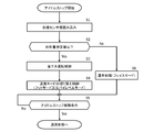
本発明によるアイドルストップ中における空調制御について、図2の制御フロー図を用いて説明する。本フローは、フェイスモードに制御された状態(通常制御)での冷房運転中、車両がアイドルストップ状態に移行したときに、実行される。本フローの開始と同時に、エンジン1は停止するので、エンジン駆動コンプレッサ3に代わって電動コンプレッサ5を運転する。
ステップS1では、制御装置30により上記各種センサ値を読み込む。
ステップS2では、上記各種センサ値のうち日射量が所定値以下であるか否かを判定する。ここで、日射量は単位面積当たりの熱量(W/m2)で表わされ、日射量が所定値以下であれば、ステップS3に進む。
ステップS2では、上記各種センサ値のうち日射量が所定値以下であるか否かを判定する。ここで、日射量は単位面積当たりの熱量(W/m2)で表わされ、日射量が所定値以下であれば、ステップS3に進む。
ステップS3では、エバポレータ22の出口空気温度の目標値を高く設定することにより、冷媒温度を上昇させ、電動コンプレッサ5の冷房負荷を低下させる。すなわち、エバポレータ22の出口空気温度の目標値を例えば10℃に設定して、電動コンプレッサ5の電力消費を低減した省エネ制御を行う(これに対し、高出力制御におけるエバポレータ22の出口空気温度の目標値は3℃である)。
ステップS4では、送風モードの切り替え制御を行う。具体的には、送風モードをフェイスモードからフットモード又はバイレベルモードに切り替える制御を行う。
ステップS5では、アイドルストップ解除条件に該当するか否かを判定する。該当する場合は、アイドルストップが解除されてエンジン1が始動するので、電動コンプレッサ5に代わってエンジン駆動コンプレッサ3を運転する。該当しない場合には、再度アイドルストップ解除条件に該当するか否かを判定する。
ステップS5では、アイドルストップ解除条件に該当するか否かを判定する。該当する場合は、アイドルストップが解除されてエンジン1が始動するので、電動コンプレッサ5に代わってエンジン駆動コンプレッサ3を運転する。該当しない場合には、再度アイドルストップ解除条件に該当するか否かを判定する。
一方、ステップS2において、日射量が所定値より大きいときは、省エネ制御及び送風モードの切り替え制御を行わない。
このとき、省エネ制御及びフェイスモード以外への切り替え制御を行ってしまうと、乗員の上半身側に向かう送風量が減少して体感温度が上昇したり、太陽熱により車室内が熱くなったりすることが懸念される。すなわち、夏季などの昼間や日差しが強いときには、コンプレッサの冷房負荷を高くして、フェイスモードにより乗員の上半身側に向かう送風量を多くする通常制御での冷房運転を行うことが要求される。
したがって、省エネ制御及び送風モードの切り替え制御は行わず、ステップS6に進み、通常制御での冷房運転を行う。その後、ステップS5に進み、アイドルストップ解除条件に該当するか否かを判定する。
このとき、省エネ制御及びフェイスモード以外への切り替え制御を行ってしまうと、乗員の上半身側に向かう送風量が減少して体感温度が上昇したり、太陽熱により車室内が熱くなったりすることが懸念される。すなわち、夏季などの昼間や日差しが強いときには、コンプレッサの冷房負荷を高くして、フェイスモードにより乗員の上半身側に向かう送風量を多くする通常制御での冷房運転を行うことが要求される。
したがって、省エネ制御及び送風モードの切り替え制御は行わず、ステップS6に進み、通常制御での冷房運転を行う。その後、ステップS5に進み、アイドルストップ解除条件に該当するか否かを判定する。
ステップS5でのエンジン駆動コンプレッサ3の運転開始後は、通常制御に移行する。
本実施形態によれば、アイドルストップ中で、日射量が所定値以下のときに、エバポレータの出口空気温度が高く設定して冷房負荷を低下させることにより、電動コンプレッサの電力消費を低減した省エネ制御での冷房運転が可能となる。
本実施形態によれば、上記のように電動コンプレッサの電力消費を低減するように冷房負荷を低下させると共に、送風モードをフェイスモードからフットモード又はバイレベルモードに切り替える制御を行うことにより、水分を含んだ空気を乗員の足元側に送風するか、又は上半身側及び足元側の両方から送風する。
すなわち、冷房が必要となる夏季などの夜間や比較的日差しが弱いときに、電動コンプレッサの省エネ制御により、十分に除湿されない空気が車室内に吹き出されても、乗員の顔や腕に直接当たる送風量が抑制される。
したがって、アイドルストップ中に、バッテリ電力の消費を抑制しつつ、乗員の不快感を軽減でき、ひいては、車室内の快適性を維持できるので、アイドルストップ可能時間を延長できる。
すなわち、冷房が必要となる夏季などの夜間や比較的日差しが弱いときに、電動コンプレッサの省エネ制御により、十分に除湿されない空気が車室内に吹き出されても、乗員の顔や腕に直接当たる送風量が抑制される。
したがって、アイドルストップ中に、バッテリ電力の消費を抑制しつつ、乗員の不快感を軽減でき、ひいては、車室内の快適性を維持できるので、アイドルストップ可能時間を延長できる。
また、図示の実施形態はあくまで本発明を例示するものであり、本発明は、説明した実施形態により直接的に示されるものに加え、特許請求の範囲内で当業者によりなされる各種の改良又は変更を包含するものであることは言うまでもない。
1…エンジン
2…冷媒回路
3…エンジン駆動コンプレッサ
4…コンデンサ
5…電動機駆動コンプレッサ
6…受液器
7…膨張弁
7a…検出部
8…冷却用ファン
9…バッテリ
10…オルタネータ
11…ラジエータ
12…ベルト
13…クラッチ
14…冷却水回路
20…HVACユニット
21…ブロア
22…エバポレータ
23…ダンパ
24…ヒータコア
25…フット吹き出し口
25a…フット弁
26…フェイス吹き出し口
26a…フェイス弁
27…デフロスタ吹き出し口
27a…デフロスタ弁
30…制御装置
40…日射量センサ
2…冷媒回路
3…エンジン駆動コンプレッサ
4…コンデンサ
5…電動機駆動コンプレッサ
6…受液器
7…膨張弁
7a…検出部
8…冷却用ファン
9…バッテリ
10…オルタネータ
11…ラジエータ
12…ベルト
13…クラッチ
14…冷却水回路
20…HVACユニット
21…ブロア
22…エバポレータ
23…ダンパ
24…ヒータコア
25…フット吹き出し口
25a…フット弁
26…フェイス吹き出し口
26a…フェイス弁
27…デフロスタ吹き出し口
27a…デフロスタ弁
30…制御装置
40…日射量センサ
Claims (3)
- アイドルストップ中に電動機駆動コンプレッサを使用して冷房する車両用空調装置において、
日射量を検出する日射量センサと、
アイドルストップ中で、前記日射量センサにより検出される日射量が所定値以下のときに、前記電動機駆動コンプレッサの電力消費を低減するように冷房負荷を低下させると共に、乗員の上半身側に向かう送風量を低下させる制御装置と、
を備えることを特徴とする、車両用空調装置。 - 前記制御装置は、エバポレータの出口空気温度の目標値を高く設定することにより、冷房負荷を低下させることを特徴とする、請求項1に記載の車両用空調装置。
- 前記制御装置は、前記乗員の上半身側に向けて送風するフェイスモードから、前記乗員の足元側に向けて送風するフットモード、又は前記乗員の上半身側及び足元側の両方に向けて送風するバイレベルモードに切り替えることで、前記乗員の上半身側へ向かう送風量を低下させることを特徴とする、請求項1又は請求項2に記載の車両用空調装置。
Applications Claiming Priority (2)
| Application Number | Priority Date | Filing Date | Title |
|---|---|---|---|
| JP2014142449A JP6357374B2 (ja) | 2014-07-10 | 2014-07-10 | 車両用空調装置 |
| JP2014-142449 | 2014-07-10 |
Publications (1)
| Publication Number | Publication Date |
|---|---|
| WO2016006279A1 true WO2016006279A1 (ja) | 2016-01-14 |
Family
ID=55063925
Family Applications (1)
| Application Number | Title | Priority Date | Filing Date |
|---|---|---|---|
| PCT/JP2015/057793 Ceased WO2016006279A1 (ja) | 2014-07-10 | 2015-03-17 | 車両用空調装置 |
Country Status (2)
| Country | Link |
|---|---|
| JP (1) | JP6357374B2 (ja) |
| WO (1) | WO2016006279A1 (ja) |
Families Citing this family (1)
| Publication number | Priority date | Publication date | Assignee | Title |
|---|---|---|---|---|
| CN105904939A (zh) * | 2016-04-06 | 2016-08-31 | 南京航空航天大学 | 基于半导体制冷技术的太阳能车用降温系统 |
Citations (5)
| Publication number | Priority date | Publication date | Assignee | Title |
|---|---|---|---|---|
| JPH04176726A (ja) * | 1990-11-09 | 1992-06-24 | Hitachi Ltd | 自動車用空気調和装置 |
| JPH0516411U (ja) * | 1991-08-20 | 1993-03-02 | 三菱自動車工業株式会社 | 車両用エアコンデイシヨナ |
| JPH0872524A (ja) * | 1994-09-09 | 1996-03-19 | Nippondenso Co Ltd | 車両用空調装置 |
| JP2004345467A (ja) * | 2003-05-21 | 2004-12-09 | Honda Motor Co Ltd | 車両用空調装置 |
| JP2010006218A (ja) * | 2008-06-26 | 2010-01-14 | Denso Corp | 車両用空調装置 |
Family Cites Families (2)
| Publication number | Priority date | Publication date | Assignee | Title |
|---|---|---|---|---|
| JP5492857B2 (ja) * | 2011-10-25 | 2014-05-14 | カルソニックカンセイ株式会社 | 車両用空調制御装置 |
| JP6172017B2 (ja) * | 2014-03-27 | 2017-08-02 | マツダ株式会社 | 車両用空調制御装置 |
-
2014
- 2014-07-10 JP JP2014142449A patent/JP6357374B2/ja active Active
-
2015
- 2015-03-17 WO PCT/JP2015/057793 patent/WO2016006279A1/ja not_active Ceased
Patent Citations (5)
| Publication number | Priority date | Publication date | Assignee | Title |
|---|---|---|---|---|
| JPH04176726A (ja) * | 1990-11-09 | 1992-06-24 | Hitachi Ltd | 自動車用空気調和装置 |
| JPH0516411U (ja) * | 1991-08-20 | 1993-03-02 | 三菱自動車工業株式会社 | 車両用エアコンデイシヨナ |
| JPH0872524A (ja) * | 1994-09-09 | 1996-03-19 | Nippondenso Co Ltd | 車両用空調装置 |
| JP2004345467A (ja) * | 2003-05-21 | 2004-12-09 | Honda Motor Co Ltd | 車両用空調装置 |
| JP2010006218A (ja) * | 2008-06-26 | 2010-01-14 | Denso Corp | 車両用空調装置 |
Also Published As
| Publication number | Publication date |
|---|---|
| JP2016016822A (ja) | 2016-02-01 |
| JP6357374B2 (ja) | 2018-07-11 |
Similar Documents
| Publication | Publication Date | Title |
|---|---|---|
| CN105163964B (zh) | 车辆用空调装置 | |
| CN104822551B (zh) | 车辆用空调装置 | |
| JP3633482B2 (ja) | ハイブリッド車両およびその空調装置 | |
| JP4321594B2 (ja) | 車両用空調装置 | |
| JP5446524B2 (ja) | 車両用空調装置 | |
| CN105263732B (zh) | 车辆用空调装置 | |
| WO2019039153A1 (ja) | 車両用空気調和装置 | |
| JP2011005982A (ja) | 車両用空調装置 | |
| WO2015025907A1 (ja) | 車両用空気調和装置 | |
| WO2020044785A1 (ja) | 車両用空気調和装置 | |
| CN110520316B (zh) | 车用空调装置 | |
| CN105555564A (zh) | 热泵式车辆用空调系统以及其除霜方法 | |
| CN106715172A (zh) | 车辆用空调装置 | |
| JP2013522116A (ja) | 暖房、換気および/または空調ループ、およびこのような暖房、換気および/または空調ループを含む暖房、換気および/または空調装置 | |
| CN114126900B (zh) | 车用空调设备 | |
| CN113165472B (zh) | 车用空调装置 | |
| WO2018221137A1 (ja) | 車両用空調装置 | |
| CN113853313A (zh) | 车辆用空气调节装置 | |
| WO2023070606A1 (zh) | 除湿模式的控制方法、装置、设备、介质及程序产品 | |
| CN116113553A (zh) | 车辆用空调装置 | |
| JP3323097B2 (ja) | ハイブリッド自動車用空気調和装置 | |
| JP2008285028A (ja) | 車両用空気調和装置 | |
| WO2015068363A1 (ja) | 車両用空調装置 | |
| JP2009166629A (ja) | 車両用空調装置 | |
| JP5494595B2 (ja) | 車両用空調装置 |
Legal Events
| Date | Code | Title | Description |
|---|---|---|---|
| 121 | Ep: the epo has been informed by wipo that ep was designated in this application |
Ref document number: 15818978 Country of ref document: EP Kind code of ref document: A1 |
|
| NENP | Non-entry into the national phase |
Ref country code: DE |
|
| 122 | Ep: pct application non-entry in european phase |
Ref document number: 15818978 Country of ref document: EP Kind code of ref document: A1 |