WO2016002942A1 - ガスセンサ素子組立体 - Google Patents
ガスセンサ素子組立体 Download PDFInfo
- Publication number
- WO2016002942A1 WO2016002942A1 PCT/JP2015/069315 JP2015069315W WO2016002942A1 WO 2016002942 A1 WO2016002942 A1 WO 2016002942A1 JP 2015069315 W JP2015069315 W JP 2015069315W WO 2016002942 A1 WO2016002942 A1 WO 2016002942A1
- Authority
- WO
- WIPO (PCT)
- Prior art keywords
- glass
- insulator
- sensor element
- gas sensor
- end point
- Prior art date
- Legal status (The legal status is an assumption and is not a legal conclusion. Google has not performed a legal analysis and makes no representation as to the accuracy of the status listed.)
- Ceased
Links
Images







Classifications
-
- G—PHYSICS
- G01—MEASURING; TESTING
- G01N—INVESTIGATING OR ANALYSING MATERIALS BY DETERMINING THEIR CHEMICAL OR PHYSICAL PROPERTIES
- G01N27/00—Investigating or analysing materials by the use of electric, electrochemical, or magnetic means
- G01N27/26—Investigating or analysing materials by the use of electric, electrochemical, or magnetic means by investigating electrochemical variables; by using electrolysis or electrophoresis
- G01N27/403—Cells and electrode assemblies
- G01N27/406—Cells and probes with solid electrolytes
- G01N27/407—Cells and probes with solid electrolytes for investigating or analysing gases
- G01N27/409—Oxygen concentration cells
-
- G—PHYSICS
- G01—MEASURING; TESTING
- G01N—INVESTIGATING OR ANALYSING MATERIALS BY DETERMINING THEIR CHEMICAL OR PHYSICAL PROPERTIES
- G01N27/00—Investigating or analysing materials by the use of electric, electrochemical, or magnetic means
- G01N27/26—Investigating or analysing materials by the use of electric, electrochemical, or magnetic means by investigating electrochemical variables; by using electrolysis or electrophoresis
- G01N27/403—Cells and electrode assemblies
- G01N27/406—Cells and probes with solid electrolytes
- G01N27/407—Cells and probes with solid electrolytes for investigating or analysing gases
- G01N27/41—Oxygen pumping cells
-
- G—PHYSICS
- G01—MEASURING; TESTING
- G01N—INVESTIGATING OR ANALYSING MATERIALS BY DETERMINING THEIR CHEMICAL OR PHYSICAL PROPERTIES
- G01N27/00—Investigating or analysing materials by the use of electric, electrochemical, or magnetic means
- G01N27/26—Investigating or analysing materials by the use of electric, electrochemical, or magnetic means by investigating electrochemical variables; by using electrolysis or electrophoresis
- G01N27/416—Systems
-
- G—PHYSICS
- G01—MEASURING; TESTING
- G01N—INVESTIGATING OR ANALYSING MATERIALS BY DETERMINING THEIR CHEMICAL OR PHYSICAL PROPERTIES
- G01N27/00—Investigating or analysing materials by the use of electric, electrochemical, or magnetic means
- G01N27/26—Investigating or analysing materials by the use of electric, electrochemical, or magnetic means by investigating electrochemical variables; by using electrolysis or electrophoresis
- G01N27/416—Systems
- G01N27/417—Systems using cells, i.e. more than one cell and probes with solid electrolytes
- G01N27/419—Measuring voltages or currents with a combination of oxygen pumping cells and oxygen concentration cells
Definitions
- the present disclosure includes a gas sensor element for detecting the concentration of a specific gas component in a gas to be measured, an insulator that accommodates and holds the gas sensor element, and a sealing glass that hermetically fixes the gas sensor element and the insulator.
- the present invention relates to a gas sensor element assembly.
- a gas sensor for detecting the concentration of a specific gas in a gas to be measured a gas sensor element having a detection portion on the tip side, a substantially cylindrical insulator that holds the sensor element inserted therein, and the insulator
- a housing constituted by a housing in which is inserted and disposed and a cover body which is disposed on the front end side of the housing and protects the sensor element.
- Laminated gas sensor elements are widely used which are formed by laminating element holding members and heater layers with built-in heating elements, etc., and having a rectangular cross section and a flat plate shape extending in the axial direction.
- Patent Document 1 discloses a gas sensor element in which a flat sensor element extending in the axial direction is housed and fixed inside a substantially cylindrical insulator via a sealing glass, and is a boundary portion between the sealing glass and the sensor element. Discloses a gas sensor element which is made of an inorganic material and has a coating layer having a multi-particle structure so as to cover 80% or more of the surface of the sealing glass while covering the outer periphery of the sensor element, and a method for manufacturing the same.
- annular groove-shaped glass filling space surrounding the outer periphery of the sensor element is provided on the base end side of the insulator, filled with sealing glass, heated and melted, and then cooled and solidified. And the insulator are hermetically fixed.
- the inventor has studied the shape of the gas sensor element assembly.
- the gas sensor element assembly 4z shown as Comparative Example 1 in FIG. 10 when a part of the outer peripheral surface on the base end side of the insulator 3z is cut out in a planar shape to form the rotation preventing portion 33, the thickness T 33 z of that portion is formed. However, it becomes thinner than the thickness (T 30 ) of the other part, the mechanical strength against the assembly load of the insulator 3z is lowered, and there is a possibility of causing a crack failure during the assembly.
- the cavity for forming the anti-rotation portion 33 is narrow, the material filling property is lowered, and distortion due to local density reduction may be caused. is there.
- the rotation preventing portion 33 is formed, and the inner peripheral surface of the glass-filled space 32y is parallel to the outer peripheral surface of the insulator 3y formed in a cross-sectional shape.
- the thickness T 33 y at the position where the anti-rotation portion 33 of the insulator 3 y is formed is made equal to the thickness (T 30 ) of the other portion, thereby improving the mechanical strength. It is thought that you can.
- the sealing glass 2 used for fixing the sensor element 1 is made of high melting point glass such as crystallized glass, aluminosilicate glass, or borosilicate glass in consideration of heat resistance.
- high melting point glass such as crystallized glass, aluminosilicate glass, or borosilicate glass in consideration of heat resistance.
- Such heat-resistant glass has a large surface tension that acts during melting, and the contact surface with the insulator tends to be rounded.
- the surface of the sensor element 1 is provided with a terminal electrode for connection to the outside, a detection electrode exposed to the gas to be measured, etc., the electrode is configured when exposed to an excessively high temperature environment. There is a possibility that the life of the electrode may be reduced due to aggregation of the metal particles.
- the heating temperature when melting the sealing glass is limited so that the electrode is not exposed to an excessively high temperature environment, and the fluidity of the sealing glass is also limited.
- the glass filling space 32y is formed by providing the inner peripheral surface of the cross-sectional oval shape parallel to the outer peripheral surface of the insulator 3 formed in the cross-sectional oval shape, as shown in FIG.
- a gap GP is formed between the inner peripheral surface of the glass filling space 32y drilled in the surface and the surface of the sealing glass 2y having an elliptical cross section due to surface tension, which may cause a decrease in airtightness.
- the rotation preventing portion is not formed on the outer peripheral surface of the insulator 3x as in the gas sensor element assembly 4x shown as the comparative example 3 in FIG. 12, in order to further reduce the size of the gas sensor,
- the outer peripheral surface of the base end side of the insulator 3x forming the glass-filled space 32x is thinned to the limit that can be formed as a peripheral wall surface, and the outer diameter ⁇ D3x of the insulator 3x is reduced, the load at the time of assembly is received. Since the cross-sectional area is small, the entire thin portion cannot withstand the assembling load, and there is a risk of causing a crack failure during assembling.
- the present disclosure provides an insulator and a sealing glass while suppressing a decrease in mechanical strength of a cylindrical insulator that accommodates and fixes a flat sensor element that has a rectangular cross section and extends in the axial direction.
- An object of the present invention is to provide a highly reliable gas sensor element assembly that improves the adhesion of the gas sensor.
- a flat plate that is exposed to a gas to be measured and includes a detection unit (10) that detects a specific component in the gas to be measured and has a rectangular cross section and extends in the axial direction.
- the cross-sectional shape of the glass filling space is an elliptical shape or a rounded polygonal shape with rounded corners.
- the cross-sectional shape of the sealing glass Shape, or, characterized in that without a rounded polygonal shape with rounded corners.
- the gap is formed between the inner peripheral surface of the glass filling space and the surface of the sealing glass while maintaining the strength at which the insulator does not crack against a predetermined load.
- a highly reliable gas sensor element assembly in which the insulator and the gas sensor element are hermetically fixed can be realized.
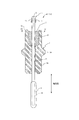
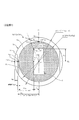
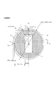
- FIG. 1 is a longitudinal sectional view of the gas sensor element assembly 4 of FIG. 1A.
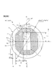
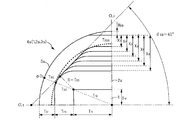
- FIG. 1B is a cross-sectional view taken along the line CC in FIG. 1B, showing details of the glass filling space 32 that is a main part of the present disclosure.
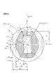
- the principal part top view for demonstrating the test method performed for optimization of the cross-sectional shape of the glass filling space 32 The characteristic view which shows the effect in 1st Embodiment of this indication with a comparative example Cross-sectional view of glass-filled space 32a that is a main part of gas sensor element assembly 4a according to the second embodiment of the present disclosure
- the principal part top view for demonstrating the test method performed for optimization of the cross-sectional shape of the glass filling space 32a The characteristic view which shows the effect in 2nd Embodiment of this indication with a comparative example Cross-sectional view of glass-filled space 32b that is a main part of gas sensor element assembly 4b according to the third embodiment of the present disclosure.
- Cross-sectional view of a glass-filled space 32d that is a main part of a gas sensor element assembly 4d according to a fifth embodiment of the present disclosure Cross-sectional view of a glass-filled space 32z, which is a main part of a conventional gas sensor element assembly 4z, shown as Comparative Example 1
- the longitudinal cross-sectional view which shows the whole gas sensor outline
- the gas sensor element assembly 4 according to the first embodiment of the present disclosure will be described with reference to FIGS. 1A, 1B, and 1C.
- Sensor element assembly 4 (hereinafter abbreviated as assembly 4) is used in a gas sensor that is provided in a combustion exhaust passage of a combustion engine and measures the concentration of a specific gas component in a gas to be measured.
- an exhaust gas discharged from an internal combustion engine such as an automobile engine is used as a gas to be measured, and an oxygen sensor that detects an oxygen component concentration in the gas to be measured will be described as an example.
- the element assembly 4 is not limited to an oxygen sensor, but can be applied to assembling various gas sensor elements such as an NH 3 sensor, a NOx sensor, an O 2 sensor, and a PM sensor according to a detection target in a gas to be measured. It is possible.
- the direction parallel to the short side of the element 1 is the short direction
- the element 1 A direction parallel to the long side is referred to as a longitudinal direction.
- the assembly 4 includes the element 1, the insulator 3, and the sealing glass 2.
- the element 1 includes a detection unit 10 that is exposed to a gas to be measured and detects a specific component in the gas to be measured, and is formed in a flat plate shape having a rectangular cross section and extending in the axial direction.
- the insulator 3 is formed in a tubular shape using a known insulating material such as alumina.
- a through hole 31 having a rectangular cross section and extending in the axial direction is provided inside the insulator 3.
- the element 1 is accommodated and held in the through hole 31.
- the insulator 3 is formed with a glass-filled space 32 in which a part of the proximal end portion is recessed and partitioned.
- a sealing glass 2 in which a known heat-resistant glass is previously formed into a cylindrical shape is disposed.
- the sealing glass 2 By melting and solidifying the sealing glass 2, the element 1 and the insulator 3 are fixed in an airtight manner to constitute an assembly 4.
- the insulator 3 is formed with a rotation preventing portion 33 formed so that a part of the outer peripheral surface thereof is cut out in a flat shape.
- the glass filling space 32 in the present embodiment has an elliptical cross-sectional shape.
- the cross-sectional shape of the sealing glass 2 in the present embodiment is an elliptical shape.
- the element 1 is a so-called laminated sensor element formed in a flat plate shape having a rectangular cross section and extending in the axial direction.
- a detection unit 10 that is exposed to the gas to be measured is provided on the tip side of the element 1.
- the detection unit 10 is opposed to a flat solid electrolyte layer (not shown) made of partially stabilized zirconia that exhibits conductivity with respect to specific ions with the solid electrolyte layer interposed therebetween, and is in contact with the gas to be measured.
- An electrode (not shown) and a reference electrode (not shown) in contact with the reference gas are provided.
- a heater (not shown) is provided that is embedded in an insulating layer (not shown) formed of an insulating material such as alumina in a flat plate shape and generates heat when energized.
- the surface of the detection unit 10 is covered with a porous protective layer 11.
- a reference gas chamber 12 for introducing the atmosphere as a reference gas is opened inside the detection unit 10.
- a pair of energization terminals 14 are provided for connection with the power source.
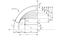
- a straight line extending vertically from the center point CP of the element 1 toward the short side of the element 1 is referred to as a long-side direction center line CL 1, and from the center point CP of the element 1 toward the long side of the element 1. the drawn vertically straight and short side direction center line CL 2.
- a distance or the like indicates a distance or the like in a plan view of a cross section perpendicular to the axial direction, as shown in FIG. 1C, unless it is clear or otherwise defined. .
- sealing glass 2 crystallized glass such as B 2 O 3 —ZnO—SiO 2 —Al 2 O 3 —BaO—MgO, refractory glass such as aluminosilicate glass and borosilicate glass is used.
- the sealing glass 2 is formed in a cylindrical shape for easy assembly of a powdery sealing glass raw material, and is inserted into a glass filling space 32 provided in the insulator 3.
- the sealing glass 2 is formed in an elliptical cross section, and a through hole for inserting the element 1 is provided at the center.
- the element 1, the insulator 3, and the sealing glass 2 are temporarily assembled and heated to about 900 ° C. to crystallize the sealing glass 2, the element 1 is in the insulator 3 through the sealing glass 2. The airtight state is maintained.
- elements of the device 1 the distance from the longitudinal end point P 11 to the glass longitudinally end point P 21 of the sealing glass 2 and the glass longitudinal thickness T 21
- glass lateral direction of the sealing glass 2 from the element widthwise direction end point P 12 of element 1 when the distance to the end point P 22 and the glass short direction thickness T 22 the relationship T 20 ⁇ T 21 ⁇ T 22 holds.
- the sealing glass 2 glass diagonal positions thickness T 20 is required to be a less than 1.0mm.
- a straight line parallel to the side of the short side of the element 1 or an arc having a radius R 21 T 10 + T 20 with the center point CP of the element 1 as the center.
- the distance L 21 from the center point CP of the element 1 to the short side edge of the sealing glass 2 can be appropriately changed within the range of T 11 + T 20 ⁇ L 21 ⁇ T 10 + T 20 .
- the longitudinal side edges of the glass diagonal positions the end point P 20 of the sealing glass 2 to the glass widthwise direction end point P 22 is the long diameter a 2, a minor axis b 2 elliptical, the center of which is the virtual center point VCP It has become.
- the virtual center point VCP in the present embodiment is perpendicular to a straight line that passes through the center point CP of the element 1 and intersects with the long side of the element 1 from the point where the diagonal extension of the element 1 and the outer peripheral edge of the sealing glass 2 intersect. It is an intersection with a straight line.
- the distance W 22 from the center point CP of the element 1 to the long side edge of the sealing glass 2 can be appropriately changed within the range of T 12 + T 20 ⁇ W 22 ⁇ T 10 + T 20 ⁇ H 33 .
- the insulator 3 is formed in a cylindrical shape using a known heat-resistant insulating material such as high-purity alumina.
- the insulator 3 includes an insulator base 30, a sensor element insertion hole 31, a glass housing portion that forms a glass filling space 32 by an inner peripheral surface thereof, a rotation preventing portion 33, and an insulator enlarged diameter portion 34. Has been.
- the sensor element insertion hole 31 is formed so as to penetrate the insulator base 30 and has a cross-sectional shape into which the element 1 having a predetermined clearance can be inserted with respect to the cross-sectional shape of the element 1.
- the inner peripheral surface is curved in an elliptical shape in order to suppress the formation of a gap between the outer peripheral surface of the sealing glass 2. Moreover, in order to prevent the local mechanical strength fall, the inner peripheral surface of the sealing glass accommodation space 32 is formed so that the insulator base 30 may have a predetermined thickness.
- Insulator diagonal positions thickness T 30 includes a extension line of the diagonal lines of the element 1, from the intersection of the outer periphery of the sealing glass 2 (glass diagonal position the end point P 20), the outer peripheral edge of the insulator base 30 This is the distance to the intersection (insulator diagonal position end point P 30 ).
- the insulator longitudinal thickness T 31 is a distance from the glass longitudinal end point P 21 of the sealing glass 2 to the insulator longitudinal end point P 31 of the insulator 3.
- the insulator detent portion thickness T 33 is the distance from the glass short-side end point P 22 of the sealing glass 2 to the end point (insulator detent position end point) P 33 of the detent portion 33 of the insulator 3.
- the notch depth H 33 is the depth of the rotation stopper 33.
- the insulator diameter-expanded portion 34 is formed in a bowl shape projecting so that a part of the insulator base portion 30 has a large diameter in the outer diameter direction, and is known as talc powder or the like when assembled to a gas sensor to be described later.
- the housing is hermetically held via the sealing member.
- the test and the result which were performed for the optimization of the cross-sectional shape of the glass filling space 32 in 1st Embodiment of this indication are demonstrated.
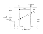
- a compressive load was applied in the axial direction of the body 3, and the limit load at which cracking occurred was measured.
- the crack was generated by the compressive load of 800 N or less.
- the detent portion thickness T 33 in the case of the above 0.68 mm was found to be able to exhibit the strength that can counter the above target load 900 N. Further, when the rotation preventing portion thickness T 33 thicker than 1.5 mm, the mechanical strength can be greater than the target load, the glass cross section longitudinal thickness T 21 of the sealing glass 2 becomes thin, molded It has been found that the gap GP increases between the inner peripheral surface of the glass filling space 32 and the outer peripheral edge of the sealing glass 2 in addition to a decrease in the packing density at the time. From the above, it has been found that in the present embodiment, it is desirable to set the insulator detent thickness T 33 to 0.68 mm or more and 1.5 mm or less.
- FIGS. 3, 4A, and 4B An assembly 4a according to the second embodiment of the present disclosure will be described with reference to FIGS. 3, 4A, and 4B.
- the same components as those in the above embodiments are denoted by the same reference numerals, and the characteristic portions in the respective embodiments are denoted by alphabetical symbols as branch numbers. The description will be omitted, and the features of the respective embodiments will be mainly described.
- the glass filling space 32a in the present embodiment is formed in a rounded octagonal shape with a rounded corner.
- T 20 on the extension of the diagonal line of the element 1, T 20 ⁇ T 21 ⁇ between the glass diagonal position wall thickness T 20 , the glass longitudinal direction wall thickness T 21 , and the glass short-side wall thickness T 22. relation of T 22 is satisfied. Further, on the extension line of the diagonal line of the element 1, T 30 ⁇ T 31 ⁇ between the insulator diagonal position thickness T 30 , the insulator longitudinal direction thickness T 31 , and the insulator detent thickness T 33. relation of T 33 is satisfied.
- the inner peripheral surface of the glass filling space 32a is parallel to the longitudinal plane of the element 1, and the inner peripheral surface on the side where the anti-rotation portion 33 is formed, and the lateral side surface of the element 1
- the inclination angle ⁇ 2 a of the inclined side of the polygonal inner peripheral surface connecting the short side inner peripheral surface parallel to the angle is set to 45 °.
- the insulator detent portion thickness T 33 a by changing to 0.5 mm ⁇ 1.75 mm, were investigated cracking load, as shown in FIG. 4B It was found that a strength of not less than a predetermined target load (900 N) can be exhibited at 0.62 mm or more.
- the inclination angle ⁇ 2 b of the inclined side of the inner peripheral surface of the polygon is set to 30 °.
- Table 1 shows the results of investigations on changes in cracking load in each example, as well as comparative examples. According to this indication, in any embodiment, it became clear that the intensity beyond a target crack load could be exhibited.
- the anti-rotation portion thicknesses T 33 , T 33 a, and T 33 b are set to 0.68 mm or more. It has been found that highly durable assemblies 4, 4a and 4b can be formed which avoid local strength reduction and exceed the target load.
- the example in which the inclination angles ⁇ 2 a and ⁇ 2 b are set to 45 ° and 30 ° when the cross-sectional shape of the sealing glasses 2a and 2b is a rounded octagon is shown.
- the shape of the outer peripheral edge of the sealing glass 2a, 2b along the shape of the inner peripheral edge of the glass-filled spaces 32a, 32b is not limited to these.
- Various rounded polygonal shapes such as a square shape and a rounded square shape may be used.
- the glass cross-sectional direction thickness T 22 and the glass diagonal position thickness T 20 and the insulator diagonal position thickness T 30 on the extension of the diagonal line of the element 1 are the thinnest.
- the rotation stopper wall thickness T 33 it is possible to exhibit a sufficient strength against a load operating in the axial direction of the insulator 3,
- the sealing glass 2, 2a, 2b it becomes difficult to form a gap between the outer peripheral edge and airtightness can be secured.
- a gas sensor element assembly 4c according to the fourth embodiment of the present disclosure will be described with reference to FIG.
- the configuration in which the anti-rotation portion 33 is provided in the insulator 3 has been described.
- the anti-rotation portion is not provided, and the outer diameter ⁇ D3c of the insulator 3c is
- the inner peripheral surface constituting the glass filling space 32c is made as thin as possible in contact with the outer diameter.
- the cross-sectional shape of the glass filling space 32c is the same elliptical shape as the gas sensor element assembly 1 in the first embodiment, so that the cross-sectional shape of the sealing glass 2c is an elliptical shape. It is formed.
- the relationship of T 30 ⁇ T 31 ⁇ T 32 c is established. Furthermore, also in this embodiment, the relationship of T 20 ⁇ T 21 ⁇ T 22 is established.
- the thinnest portion it is possible to make up for the insufficient strength at the diagonal position of the insulator and relatively increase the strength of the base end side of the insulator 3c.
- the base end side of the insulator 3c insulator diagonal positions thickness T 30 of the thinnest portion of the peripheral wall portion forming a glass-filled space 32c in, for example, more than 0.65 mm, the thickest portion to become the insulator lateral direction thickness T 32 c is It was found that the effect of the present disclosure can be exhibited if the thickness is 0.83 mm or more.
- no detent portion is provided, and the outer diameter ⁇ D3d of the insulator 3d is made as thin as possible.
- the cross-sectional shape of the glass filling space 32d is a rounded polygonal shape with rounded corners, similar to the gas sensor element assemblies 4a and 4b in the second and third embodiments.
- the cross-sectional shape of the sealing glass 2d is a rounded polygonal shape with rounded corners.
- the thickness T 33 z of the portion forming the rotation stopper 33 is the thickness of the other portion (T 30) It has become. For this reason, the mechanical strength with respect to the assembly load of the insulator 3z is lowered, and there is a possibility of causing a crack defect during the assembly.
- the cavity for forming the anti-rotation portion 33 is narrow, the material filling property is lowered, and distortion due to local density reduction may be caused. there were.
- the rotation preventing portion 33 is formed, and the inner peripheral surface of the glass filling space 32y is formed in a cross-sectional oval shape in parallel with the outer peripheral surface of the insulator 3y formed in a cross-sectional oval shape.
- the thickness T 33 y at the position where the anti-rotation portion 33 of the insulator 3 y is formed is formed to be equal to the thickness T 30 of other portions.
- the outer peripheral surface is thinned to the limit that can be formed as a peripheral wall surface, and the outer diameter ⁇ D3x of the insulator 3x is reduced.
- the wall thickness T 30 x on the base end side of the insulator 3 is extremely thin, the cavity formed in the mold used at the time of molding is narrow, the compactness is lowered, and the cross-sectional area that receives the load at the time of assembly Therefore, the entire thin-walled portion cannot withstand the assembly load, and there is a risk of causing a crack failure during assembly.
- the gas sensor 8 includes an assembly 4, a housing 5, a cover body 6, and a gas sensor base end portion 7.
- the housing 5 is made of a known metal material such as iron, nickel, alloys thereof, carbon steel, and stainless steel.
- the housing 5 includes a housing base 50, an assembly housing portion 51, an assembly locking portion 52, a large-diameter cylindrical portion 53, a caulking portion 54, a cover caulking portion 55, and a screw portion 56. Has been.
- An assembly housing portion 51 is formed inside the housing base 50, and an assembly locking portion 52 that changes in diameter so as to increase in diameter toward the proximal end side at the proximal end side of the assembly housing portion 51. Further, a large-diameter cylindrical portion 53 into which the insulator enlarged-diameter portion 34 can be inserted is formed on the proximal end side.
- the front end side of the assembly 4 according to the present disclosure is accommodated.
- the surface on the distal end side of the insulator expanded diameter portion 34 of the assembly 4 is in direct or indirect contact with the assembly locking portion 52. Further, a known powder filler 57 such as talc or a seal member is filled in a space defined by the insulator enlarged diameter portion 34, the caulking portion 54, and the large diameter cylindrical portion 53. A force is applied to press the insulator enlarged diameter portion 34 so as to be hermetically fixed.
- a known powder filler 57 such as talc or a seal member is filled in a space defined by the insulator enlarged diameter portion 34, the caulking portion 54, and the large diameter cylindrical portion 53.
- the screw portion 56 is screwed into the measurement gas flow path 81 through which the measurement gas 80 flows, and holds the detection unit 10 provided at the tip of the element 1 in the measurement gas 80.
- the cover body 6 is provided in a bottomed cylindrical shape.
- the cover base 60 is provided with an introduction hole 61 for introducing a gas to be measured inside.
- the base end side of the cover body 6 is caulked and fixed by a cover body caulking portion 55 provided at the distal end of the housing 5.
- this figure shows a cover body having a double cylinder structure, the present disclosure is not particularly limited and can be appropriately changed.
- the gas sensor base end portion 7 includes a casing 70, an insulator 71, a pair of signal terminal fittings 72, a pair of energizing terminal fittings 73, a pair of signal wires 74, a pair of energizing wires 75, and a water repellent filter 76. And a grommet 78.
- the casing 70 is formed in a cylindrical shape using a known metal material such as stainless steel.
- the casing 70 covers the base end side of the housing 5 and accommodates an insulator 71, a pair of signal terminal fittings 72, a pair of energizing terminal fittings 73, a pair of signal wires 74, and a pair of energizing wires 75 inside.
- the base end side is airtightly held through a grommet 78. Ventilation holes 761 and 762 are formed in the casing 70 to communicate the inside of the gas sensor 8 with the atmosphere via the water repellent filter 76.
- the water-repellent filter 76 is made of a known water-repellent porous membrane that blocks liquid and allows gas to pass through, and prevents water droplets from entering when air is introduced as a reference gas.
- a pair of signal electrodes 13 and a pair of heater electrodes 14 provided at the base end of the element 1 are formed.
- the signal terminal fitting 72, the conduction terminal fitting 73, the pair of signal lines 74, and the conduction line 75 are externally provided. It is connected to a not-shown calculation unit and power supply control unit.
- the signal terminal fitting 72 and the energizing terminal fitting 73 are made of a known conductive material such as stainless steel or copper, and the distal end side is formed in a spring shape, elastically contacts the signal terminal 13 and the energizing terminal 14, and on the proximal end side.
- the signal line 74 and the energization line 75 are pressure-bonded to achieve electrical connection between the element 1 and the outside.
- the insulator 71 is made of a known insulating material such as alumina, and maintains insulation between the signal terminal fitting 72, the energizing terminal fitting 73 and the casing 70.
- the rotation prevention portion 33 provided on the insulator 3 of the assembly 4 and the insulator 71 are fitted to each other, the direction of the electrodes 13 and 14 provided on the element 1 and the pressing direction of the signal terminal fitting 72 and the energizing terminal fitting 73. And match.
- the casing 70 is fitted and fixed so as to cover the outer periphery of the large-diameter cylindrical portion 53 of the housing 5.
- the caulking portion 77 compresses the grommet 78 and hermetically seals the proximal end side of the casing 70.
- the gas sensor element assembly of the present disclosure may be an oxygen sensor, an air-fuel ratio sensor, an ammonia sensor, a NOx sensor, a PM sensor, a humidity sensor, or the like that has a sensor element with a rectangular cross section and a flat plate shape extending in the axial direction.
- it can be used for various sensors regardless of the fluid to be measured.
Landscapes
- Chemical & Material Sciences (AREA)
- Life Sciences & Earth Sciences (AREA)
- Health & Medical Sciences (AREA)
- Physics & Mathematics (AREA)
- Chemical Kinetics & Catalysis (AREA)
- Electrochemistry (AREA)
- Molecular Biology (AREA)
- Analytical Chemistry (AREA)
- Biochemistry (AREA)
- General Health & Medical Sciences (AREA)
- General Physics & Mathematics (AREA)
- Immunology (AREA)
- Pathology (AREA)
- Measuring Oxygen Concentration In Cells (AREA)
Abstract
断面矩形で軸方向に延びる平板状のセンサ素子を収容固定する筒状の絶縁体の外周面の一部を平面状に切り欠いた回り止め部を設けたり、ガラス外径を極限まで細くしたりしても、絶縁体の機械的強度の低下を抑制しつつ、絶縁体と封止ガラスとの密着性の向上を図った信頼性の高いガスセンサ素子組立体を提供する。回り止め部33を具備する絶縁体3に設けた封止ガラス2を充填するためのガラス充填空間32の内周面を断面楕円形状又は角を丸めた断面角丸多角形状に形成することで、封止ガラス2を断面楕円形状又は角を湾曲させた断面角丸多角形状とすると共に、ガスセンサ素子1の対角線の延長線上における封止ガラス2のガラス対角位置肉厚T20が、封止ガラス2の他の部分の肉厚T21、T22よりも薄く、かつ、絶縁体3の対角位置肉厚T30が、絶縁体3の他の部分T31、T33の肉厚よりも薄くなるように設定する。
Description
本出願は、2014年7月3日にされた日本出願番号2014-137370号に基づくもので、ここにその記載内容を援用する。
本開示は被測定ガス中の特定ガス成分の濃度を検出するためのガスセンサ素子と、そのガスセンサ素子を収容保持する絶縁体と、ガスセンサ素子と絶縁体とを気密に固定する封止ガラスとを有するガスセンサ素子組立体に関する。
従来、被測定ガス中の特定ガスの濃度を検出するためのガスセンサとして、先端側に検出部を有したガスセンサ素子と、該センサ素子を内側に挿入保持する略筒状の絶縁碍子と該絶縁碍子が挿入配設されたハウジングと、該ハウジングの先端側に配設され上記センサ素子を保護するカバー体とによって構成されたものが知られている。
このようなガスセンサに用いられるガスセンサ素子として、ジルコニア等の特定のイオンに対して伝導性を有する固体電解質層と、少なくともその対向する表面に形成した一対の電極対と、アルミナ等の絶縁性材料を用いて形成された素子保持部材や発熱体を内蔵したヒータ層等を積層し、断面矩形で、軸方向に伸びる平板状に形成した積層型のガスセンサ素子が広く用いられている。
特許文献1には、封止ガラスを介して略筒状の絶縁体の内側に軸方向に延びる平板状のセンサ素子を収納固定したガスセンサ素子であって、封止ガラスとセンサ素子との境界部において、センサ素子の外周を覆いつつ、封止ガラスの表面の80%以上を覆うように無機材料からなり、多粒子構造を有するコーティング層を設けたガスセンサ素子とその製造方法が開示されている。
従来のガスセンサ素子では、絶縁体の基端側にセンサ素子の外周を取り囲む環溝状のガラス充填空間を設けて、封止ガラスを充填し、加熱熔融した後、冷却固化させることで、センサ素子と絶縁体とを気密に固定している。
本発明者はガスセンサ素子組立体の形状について検討を行った。図10に比較例1として示すガスセンサ素子組立体4zにおいて、絶縁体3zの基端側外周面の一部を平面状に切り欠いて回り止め部33を形成すると、その部分の肉厚T33zが他の部分の肉厚(T30)よりも薄肉となり、絶縁体3zの組み付け荷重に対する機械的強度が低下し、組み付け時に割れ不良を発生させる虞がある。
また、絶縁体3zを金型等を用いて成型する際に、回り止め部33を形成するためのキャビティが狭く、材料の充填性が低下して、局所的な密度低下による歪みを招く虞もある。
そこで、比較例2として図11に示すように、回り止め部33が形成され、断面小判型に形成された絶縁体3yの外周面と並行となるように、ガラス充填空間32yの内周面を断面小判型に形成することで、絶縁体3yの回り止め部33を形成位置の肉厚T33yを他の部分の肉厚(T30)と均等にして、機械的強度の向上を図ることができると考えられる。
一方、センサ素子1の固定に用いられる封止ガラス2には、耐熱性を考慮して、結晶化ガラス、アルミノシリケートガラス、ホウ珪酸ガラス等の高融点ガラスが用いられている。このような、耐熱性ガラスは、熔融時に作用する表面張力が大きく、絶縁体との接触面が丸くなり易い傾向がある。
さらに、センサ素子1の表面には、外部との接続を図るための端子電極や、被測定ガスに晒される検出電極などが設けられているため、過剰な高温環境に晒されると電極を構成する金属粒子の凝集による電極寿命の低下を招く虞がある。
このため、電極が過剰な高温環境に晒されないよう、封止ガラスを熔融する際の加熱温度が制限され、封止ガラスの流動性も制限されている。
このため、断面小判型に形成された絶縁体3の外周面と並行となるような断面小判型の内周面を設けてガラス充填空間32yを形成すると、図11に示すように、断面小判型に穿設されたガラス充填空間32yの内周面と表面張力によって断面楕円状となった封止ガラス2yの表面との間に間隙GPが形成され、気密性の低下を招く虞がある。
さらに、図12に比較例3として示すガスセンサ素子組立体4xように、絶縁体3xの外周面に回り止め部を形成していない構成において、ガスセンサの更なる小型化を図るべく、環溝状のガラス充填空間32xを形成する絶縁体3xの基端側外周面が周壁面として形成可能な極限まで薄くして、絶縁体3xの外径φD3xを細くした場合には、組付け時の荷重を受ける断面積が小さくなるため、薄肉部全体が組み付け荷重に耐え切れなくなり、組み付け時に割れ不良を発生させる虞もある。
そこで、かかる実情に鑑み、本開示は、断面矩形で軸方向に延びる平板状のセンサ素子を収容固定する筒状の絶縁体の機械的強度の低下を抑制しつつ、絶縁体と封止ガラスとの密着性の向上を図った信頼性の高いガスセンサ素子組立体を提供することを目的とする。
本開示のガスセンサ素子組立体(4、4a~4d)では、被測定ガスに晒され、被測定ガス中の特定成分を検出する検出部(10)を具備し、断面矩形で軸方向に延びる平板状のガスセンサ素子(1)と、内側に断面矩形で軸方向に延びる貫通孔(31)を具備し、該貫通孔に前記ガスセンサ素子を収容保持する筒状の絶縁体(3、3a~3d)と、該絶縁体の一部を窪ませて区画したガラス充填空間(32、32a~32d)に配設した筒状の封止ガラス(2、2a~2d)と、を有し、前記封止ガラスを熔融固化して前記ガスセンサ素子と前記絶縁体とを気密に固定したガスセンサ素子組立体において、前記ガラス充填空間の横断面形状を、楕円形状、又は、角を丸めた角丸多角形状とすることで、前記封止ガラスの横断面形状を、楕円形状、又は、角を丸めた角丸多角形状となしたことを特徴とする。
本開示によれば、前記絶縁体が所定の荷重に対して割れを生じない強度を維持しつつ、前記ガラス充填空間の内周面と前記封止ガラスの表面との間に間隙を形成することなく、前記絶縁体と前記ガスセンサ素子とが気密に固定された信頼性の高いガスセンサ素子組立体が実現できる。
図1A、図1B、図1Cを参照して本開示の第1の実施形態におけるガスセンサ素子組立体4について説明する。
センサ素子組立体4(以下、組立体4と略す。)は、燃焼機関の燃焼排気流路に設けられ被測定ガス中の特定ガス成分の濃度を測定するガスセンサに用いられるものである。
なお、以下の説明においては、自動車エンジン等の内燃機関から排出される燃焼排気を被測定ガスとし、被測定ガス中の酸素成分濃度を検出する酸素センサを例に説明するが、本開示のガスセンサ素子組立体4は、酸素センサに限定されるものではなく、被測定ガス中の検出対象に応じて、NH3センサ、NOxセンサ、O2センサ、PMセンサ等の様々なガスセンサ素子の組み付けに適用し得るものである。
なお、以下の説明において、断面矩形で軸方向に延びる平板状のガスセンサ素子1(以下、素子1と略す。)の横断面において、素子1の短辺に平行な方向を短手方向、素子1の長辺に平行な方向を長手方向と称する。
組立体4は、素子1と絶縁体3と封止ガラス2とによって構成されている。
素子1は、被測定ガスに晒され、被測定ガス中の特定成分を検出する検出部10を具備し、断面矩形で軸方向に延びる平板状に形成されている。
絶縁体3は、アルミナ等の公知の絶縁材料が用いられ、筒状に形成されている。
絶縁体3の内側には、断面矩形で軸方向に延びる貫通孔31を具備する。
貫通孔31には素子1が収容保持される。
絶縁体3には、基端側端部の一部を窪ませて区画したガラス充填空間32が形成されている。
絶縁体3の内側には、断面矩形で軸方向に延びる貫通孔31を具備する。
貫通孔31には素子1が収容保持される。
絶縁体3には、基端側端部の一部を窪ませて区画したガラス充填空間32が形成されている。
ガラス充填空間32には、公知の耐熱性ガラスを予め筒状に形成した封止ガラス2が配設されている。
封止ガラス2を熔融固化することで、素子1と絶縁体3とが気密に固定され、組立体4を構成している。
封止ガラス2を熔融固化することで、素子1と絶縁体3とが気密に固定され、組立体4を構成している。
絶縁体3には、その外周面の一部を平面状に切り欠くように形成した回り止め部33が形成されている。
本実施形態におけるガラス充填空間32は、その横断面形状を、楕円形状としている。
本実施形態における封止ガラス2の横断面形状は、楕円形状となっている。
素子1は、断面矩形で軸方向に伸びる平板状に形成された、いわゆる積層型のセンサ素子である。
素子1の先端側には、被測定ガス中に晒される検出部10が設けられている。
素子1の先端側には、被測定ガス中に晒される検出部10が設けられている。
検出部10には、特定のイオンに対して伝導性を示す部分安定化ジルコニアからなる平板状の固体電解質層(図示しない。)と、固体電解質層を挟んで対向し、被測定ガスに接する測定電極(図示しない。)と、基準ガスに接する基準電極(図示しない。)とが設けられている。
また、検出部10を加熱活性化すべく、アルミナ等の絶縁材料を平板状に形成した絶縁層(図示しない。)に埋設され、通電により発熱するヒータ(図示しない。)が設けられている。
検出部10の表面は、多孔質保護層11によって覆われている。
検出部10の表面は、多孔質保護層11によって覆われている。
素子1の基端には、検出部10の内側に基準ガスとして大気を導入する基準ガス室12が開口している。
素子1の基端側表面には、外部に設けた図略の演算部と基準電極層及び測定電極層との導通を図る一対の信号端子13と、検出部10に設けたヒータと外部に設けた電源との導通を図る一対の通電端子14が設けられている。
素子1の基端側表面には、外部に設けた図略の演算部と基準電極層及び測定電極層との導通を図る一対の信号端子13と、検出部10に設けたヒータと外部に設けた電源との導通を図る一対の通電端子14が設けられている。
以下の説明において、素子1の中心点CPから素子1の短辺に向かって垂直に下ろした直線を長辺方向中心線CL1とし、素子1の中心点CPから素子1の長辺に向かって垂直に下ろした直線を短辺方向中心線CL2とする。また、距離等を定義している場合は、明らかな場合や他に定義がある場合を除き、図1Cに示すように、軸方向に垂直な断面を平面視した場合における距離等を指している。
素子1は、断面矩形で中心点CPから対角線に沿った素子1の頂点となる素子対角位置端点P10までの距離を素子対角長さT10とし、中心点CPから素子長手方向端点P11までの距離を素子長手方向長さT11とし、中心点CPから素子短手方向端点P12までの距離を素子短手方向長さT12としたとき、T10
2=T11
2+T12
2の関係にある。
封止ガラス2には、B2O3-ZnO-SiO2-Al2O3-BaO-MgOなどの結晶化ガラス、アルミノシリケートガラス、ホウ珪酸ガラス等の高融点ガラスが用いられている。
封止ガラス2は、粉末状の封止ガラス原料を組付け容易にするために筒状に形成し、絶縁体3に設けたガラス充填空間32内に挿入する。
封止ガラス2は、粉末状の封止ガラス原料を組付け容易にするために筒状に形成し、絶縁体3に設けたガラス充填空間32内に挿入する。
本実施形態においては、封止ガラス2は、断面楕円形状に形成され、中心に素子1を挿入するための貫通孔が設けられている。
素子1と絶縁体3と封止ガラス2とを仮組みしたものを900℃程度に加熱して、封止ガラス2を結晶析出処理すると、封止ガラス2を介して素子1が絶縁体3内に気密に保持された状態となる。
素子1と絶縁体3と封止ガラス2とを仮組みしたものを900℃程度に加熱して、封止ガラス2を結晶析出処理すると、封止ガラス2を介して素子1が絶縁体3内に気密に保持された状態となる。
より具体的には、素子1の対角線の延長線と封止ガラス2の端縁との交わるガラス対角位置端点P20までの肉厚をガラス対角位置肉厚T20とし、素子1の素子長手方向端点P11から封止ガラス2のガラス長手方向端点P21までの距離をガラス長手方向肉厚T21とし、素子1の素子短手方向端点P12から封止ガラス2のガラス短手方向端点P22までの距離をガラス短手方向肉厚T22としたとき、T20≦T21<T22の関係が成り立つ。
なお、封止ガラス2を成形する都合から、ガラス対角位置肉厚T20は、1.0mm以上とすることを要する。
さらに、封止ガラス2のガラス対角位置端点P20からガラス長手方向端点P21までの短辺側端縁は、素子1の素子対角位置端点P10を中心とする半径R20=T20の円弧と素子1の短辺側側面に平行な直線とを結んだ曲線ないし、素子1の中心点CPを中心とし、半径R21=T10+T20の円弧によって形成されている。
素子1の中心点CPから封止ガラス2の短辺側端縁までの距離L21は、T11+T20≦L21≦T10+T20の範囲で適宜変更可能である。
さらに、封止ガラス2のガラス対角位置端点P20からガラス長手方向端点P21までの短辺側端縁は、素子1の素子対角位置端点P10を中心とする半径R20=T20の円弧と素子1の短辺側側面に平行な直線とを結んだ曲線ないし、素子1の中心点CPを中心とし、半径R21=T10+T20の円弧によって形成されている。
素子1の中心点CPから封止ガラス2の短辺側端縁までの距離L21は、T11+T20≦L21≦T10+T20の範囲で適宜変更可能である。
また、封止ガラス2のガラス対角位置端点P20からガラス短手方向端点P22までの長手方向側端縁は、仮想中心点VCPを中心とする長径a2、短径b2の楕円状となっている。
本実施例における仮想中心点VCPは、素子1の対角線の延長線と封止ガラス2の外周縁とが交わる点から素子1の中心点CPを通り、素子1の長辺に直交する直線に垂直に下ろした直線との交点となっている。
素子1の中心点CPから封止ガラス2の長辺側端縁までの距離W22は、T12+T20<W22≦T10+T20-H33の範囲で適宜変更可能である。
素子1の中心点CPから封止ガラス2の長辺側端縁までの距離W22は、T12+T20<W22≦T10+T20-H33の範囲で適宜変更可能である。
また、封止ガラス2の流動性の点から、1.25mm≦W22とすることが望ましいことが判明した。
但し、仮想中心点VCPの位置はこれに限定するものではなく、後述する試験によって明らかとなった範囲で適宜変更可能である。
但し、仮想中心点VCPの位置はこれに限定するものではなく、後述する試験によって明らかとなった範囲で適宜変更可能である。
絶縁体3は、高純度アルミナ等の公知の耐熱性絶縁材料を用いて筒状に形成されている。
絶縁体3は、絶縁体基部30と、センサ素子挿通孔31と、その内周面によりガラス充填空間32を形成するガラス収容部と、回り止め部33と、絶縁体拡径部34とによって構成されている。
絶縁体3は、絶縁体基部30と、センサ素子挿通孔31と、その内周面によりガラス充填空間32を形成するガラス収容部と、回り止め部33と、絶縁体拡径部34とによって構成されている。
絶縁体基部30は、外形φD3(=2(T10+T20+T30))の円柱状に形成されている。
センサ素子挿通孔31は、絶縁体基部30を貫通するように穿設され、素子1の断面形状に対して、所定のクリアランスを設けた素子1を挿入可能な断面形状となっている。
本実施形態におけるガラス充填空間32は、封止ガラス2の外周面との間に間隙が形成されるのを抑制するため、内周面が楕円状に湾曲している。
また、局所的な機械的強度の低下を防ぐため、絶縁体基部30が所定の肉厚を有するように封止ガラス収容空間32の内周面が形成されている。
また、局所的な機械的強度の低下を防ぐため、絶縁体基部30が所定の肉厚を有するように封止ガラス収容空間32の内周面が形成されている。
絶縁体対角位置肉厚T30は、素子1の対角線の延長線と、封止ガラス2の外周縁との交点(ガラス対角位置端点P20)から、絶縁体基部30の外周縁との交点(絶縁体対角位置端点P30)までの距離である。
絶縁体長手方向肉厚T31は、封止ガラス2のガラス長手方向端点P21から絶縁体3の絶縁体長手方向端点P31までの距離である。
絶縁体長手方向肉厚T31は、封止ガラス2のガラス長手方向端点P21から絶縁体3の絶縁体長手方向端点P31までの距離である。
ガスセンサ素子1の中心CPから素子1の長辺に向かって垂直に下ろした短辺方向中心線CL2と封止ガラス2の外周縁との交点(ガラス短手方向端点)P22から、短辺方向中心線CL2と絶縁体3の外周縁との交点(絶縁体短手方向端点P32)までの距離を絶縁体短手方向肉厚T32としたとき、
T30≦T31<T32の関係が成り立っている。
T30≦T31<T32の関係が成り立っている。
絶縁体回り止め部肉厚T33は、封止ガラス2のガラス短手方向端点P22から絶縁体3の回り止め部33の端点(絶縁体回り止め位置端点)P33までの距離である。
切欠深さH33は、回り止め部33の深さである。
T30≦T31≦T30+T10-T11、
T10+T30-H33-T12<T33≦T10+T20-H33の関係が成り立つ。
切欠深さH33は、回り止め部33の深さである。
T30≦T31≦T30+T10-T11、
T10+T30-H33-T12<T33≦T10+T20-H33の関係が成り立つ。
絶縁体拡径部34は、絶縁体基部30の一部を外径方向に向かった径大となるように張り出した鍔状に形成され、後述するガスセンサに組み付けされる際にタルク粉末等の公知の封止部材を介してハウジングによって気密に保持されるようになっている。
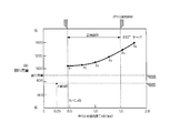
図2A、図2Bを参照して、本開示の第1の実施形態におけるガラス充填空間32の断面形状の最適化のために行った試験とその結果について説明する。
素子1として、断面方向の横幅4.0mm、板厚1.6mmを用いた。
即ち、前述のT11=2.0mm、T12=0.8mm、T10≒2.15mmとなっている。
素子1として、断面方向の横幅4.0mm、板厚1.6mmを用いた。
即ち、前述のT11=2.0mm、T12=0.8mm、T10≒2.15mmとなっている。
絶縁体3の外形φD3を7.60mmとし、回り止め部深さH33を0.25mmとし、ガラス対角位置肉厚T20を1.0mm、絶縁体対角位置肉厚T30を0.65mmとしたとき、回り止め部33の端縁から封止ガラス2の端縁までの距離、即ち、回り止め部肉厚T33を0.5mmから1.75mmまで段階的に変化させ、絶縁体3の軸方向に圧縮荷重を負荷して、割れの発生した限界荷重を計測した。
その結果、従来の比較例1では、800N以下の圧縮荷重によって割れを生じた。
その結果、従来の比較例1では、800N以下の圧縮荷重によって割れを生じた。
本開示の第1の実施形態においては、回り止め部肉厚T33を0.68mm以上とした場合に、900N以上の目標荷重に対抗できる強度を発揮できることが判明した。
また、回り止め部肉厚T33を1.5mmよりも厚くすると、機械的強度は目標荷重を超えることができるが、封止ガラス2のガラス断面長手方向肉厚T21が薄くなるため、成形時の充填密度が低下するのに加え、ガラス充填空間32の内周面と封止ガラス2の外周縁との間に間隙GPが大きくなることが判明した。
以上のことから、本実施形態においては、絶縁体回り止め部肉厚T330.68mm以上、1.5mm以下とするのが望ましいことが判明した。
また、回り止め部肉厚T33を1.5mmよりも厚くすると、機械的強度は目標荷重を超えることができるが、封止ガラス2のガラス断面長手方向肉厚T21が薄くなるため、成形時の充填密度が低下するのに加え、ガラス充填空間32の内周面と封止ガラス2の外周縁との間に間隙GPが大きくなることが判明した。
以上のことから、本実施形態においては、絶縁体回り止め部肉厚T330.68mm以上、1.5mm以下とするのが望ましいことが判明した。
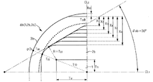
図3、図4A、図4Bを参照して、本開示の第2の実施形態における組立体4aについて説明する。
なお、以下の実施形態においては、前記実施形態と同様の構成について同じ符号を付し、それぞれの実施形態における特徴的な部分に枝番としてアルファベットの記号を付したので、前記実施形態と同じ部分については説明を省略し、それぞれの実施形態における特徴を中心に説明する。
なお、以下の実施形態においては、前記実施形態と同様の構成について同じ符号を付し、それぞれの実施形態における特徴的な部分に枝番としてアルファベットの記号を付したので、前記実施形態と同じ部分については説明を省略し、それぞれの実施形態における特徴を中心に説明する。
本実施形態におけるガラス充填空間32aは、角部がR状に湾曲する断面角丸八角形状に形成されている。
本実施形態では、素子1の対角線の延長線上において、ガラス対角位置肉厚T20、ガラス長手方向肉厚T21、ガラス短手方向肉厚T22との間に、T20≦T21<T22の関係が成り立つ。
また、素子1の対角線の延長線上において、絶縁体対角位置肉厚T30、絶縁体長手方向肉厚T31、絶縁体回り止め部肉厚T33との間に、T30≦T31≦T33の関係が成り立つ。
また、八角形の各頂角は、半径R=T20で湾曲する丸角に形成されている。
また、素子1の対角線の延長線上において、絶縁体対角位置肉厚T30、絶縁体長手方向肉厚T31、絶縁体回り止め部肉厚T33との間に、T30≦T31≦T33の関係が成り立つ。
また、八角形の各頂角は、半径R=T20で湾曲する丸角に形成されている。
さらに、ガラス充填空間32aの内周面の内、素子1の長手方向平面に対して平行で、回り止め部33が形成された側の回り止め側内周面と、素子1の短手方向側面に対して平行な短手側内周面との間を繋ぐ多角内周面傾斜辺の傾斜角度θ2aは、45°に設定してある。
本実施形態においても、図4Aに示すように、絶縁体回り止め部肉厚T33aを、0.5mm~1.75mmまで変化させて、割れ荷重を調査したところ、図4Bに示すように、0.62mm以上で所定の目標荷重(900N)以上の強度を発揮できることが判明した。
図5、図6A、図6Bを参照して、本開示の第3の実施形態における組立体4bについて説明する。
本実施形態においては、多角内周面傾斜辺の傾斜角度θ2bを30°に設定してある。
本実施形態においては、図6Aに示すように、絶縁体回り止め部肉厚T33bを0.45mm~1.75mm迄変化させたとき、0.45mm以上で、割れ荷重の向上を図ることができることが判明した。
また、本実施形態においても、前記実施形態と同様、絶縁体回り止め部肉厚T33bが1.5mmを超えると、封止ガラス2bの充填性の低下や、流動性の低下により間隙GPの形成が懸念される。
また、本実施形態においても、前記実施形態と同様、絶縁体回り止め部肉厚T33bが1.5mmを超えると、封止ガラス2bの充填性の低下や、流動性の低下により間隙GPの形成が懸念される。
表1は、比較例とともに、各実施例における割れ発生荷重の変化に対する調査結果を示す。
本開示によれば、いずれの実施形態においても、目標割れ荷重以上の強度を発揮できることが判明した。

本開示によれば、いずれの実施形態においても、目標割れ荷重以上の強度を発揮できることが判明した。
さらに、図7に示すように、本開示の効果をまとめると、いずれの実施形態においても、回り止め部肉厚T33、T33a、T33bを、0.68mm以上、とすることで、局所的な強度低下を回避し、目標荷重を超える、耐久性の高い組立体4、4a、4bを形成できることが判明した。
なお、上記実施形態においては、封止ガラス2a、2bの横断面形状を角丸八角形とした場合において、傾斜角度θ2a、θ2bをそれぞれ45°と30°とした例を示したが、本開示においては、ガラス充填空間32a、32bの内周縁の形状に沿った封止ガラス2a、2bの外周縁の形状をこれらに限定するものではなく、角丸六角形や、角丸十二角形や、角丸二十四角形など様々な角丸多角形状としても良い。
この場合においても、素子1の対角線の延長線上におけるガラス対角位置肉厚T20及び絶縁体対角位置肉厚T30が、最薄となるように、ガラス断面短手方向肉厚T22及び回り止め部肉厚T33を設定することで、絶縁体3の軸方向に作用する荷重に対して十分な強度を発揮することができる、
また、ガラス充填空間32の内周面を多角形に形成した場合、隣り合う二辺が交叉することで形成される角部に所定のRを設けることで、封止ガラス2、2a、2bの外周縁との間に間隙が形成され難くなり、気密性を確保できる。
図8を参照して、本開示の第4の実施形態におけるガスセンサ素子組立体4cについて説明する。
前記実施形態においては、絶縁体3に回り止め部33を設けた構成について説明したが、本実施形態における絶縁体3cにおいては、回り止め部を設けておらず、絶縁体3cの外径φD3cをガラス充填空間32cを構成する内周面が外径に内接するほど極限まで細くしている。
本実施形態においては、ガラス充填空間32cの横断面形状を、第1の実施形態におけるガスセンサ素子組立体1と同様の楕円形状、とすることで、封止ガラス2cの横断面形状を楕円形状に形成してある。
本実施形態においても、T30≦T31<T32cの関係が成り立っている。
さらに、本実施形態においても、T20≦T21<T22の関係が成り立っている。
さらに、本実施形態においても、T20≦T21<T22の関係が成り立っている。
本実施形態においては、ガラス充填空間32の横断面形状を楕円状とすることで、絶縁体3cの絶縁体短手方向肉厚T32cを厚肉に形成することで、最薄部となる絶縁体対角位置の強度不足を補い、絶縁体3cの基端側の強度を相対的に強くすることができる。
本実施形態においては、前記実施形態と同程度の大きさの素子1(例えば、板厚2T12=1.6mm×横幅2T11=4.0mm)を使用した場合、絶縁体3cの基端側においてガラス充填空間32cを形成する周壁部の最薄部となる絶縁体対角位置肉厚T30が、例えば、0.65mm以上、最厚部となる絶縁体短手方向肉厚T32cが0.83mm以上であれば、本開示の効果を発揮し得ることが判明した。
図9を参照して、本開示の第5の実施形態における組立体4dについて説明する。
本実施形態においても、第4の実施形態と同様、回り止め部を設けておらず、絶縁体3dの外径φD3dを極限まで細くしている。
さらに、本実施形態においては、ガラス充填空間32dの横断面形状を、第2、第3の実施形態におけるガスセンサ素子組立体4a、4bと同様、角を丸めた角丸多角形状とすることで、封止ガラス2dの横断面形状を、角を丸めた角丸多角形状としている。
このような構成とすることで、第3の実施形態と同様の効果を発揮できる。
このような構成とすることで、第3の実施形態と同様の効果を発揮できる。
図10、図11、図12に、それぞれ、比較例1、比較例2、比較例3として示す、本開示の効果を発揮し得ない組立体4z、4y、4xについて説明する。
比較例1では、ガラス充填空間32zの内周面が円形に形成されており、回り止め部33を形成した部分の肉厚T33zが他の部分の肉厚(T30)よりも薄肉となっている。このため、絶縁体3zの組み付け荷重に対する機械的強度が低下し、組み付け時に割れ不良を発生させる虞があった。
また、絶縁体3zを金型等を用いて成型する際に、回り止め部33を形成するためのキャビティが狭く、材料の充填性が低下して、局所的な密度低下による歪みを招く虞もあった。
比較例2では、回り止め部33が形成され、断面小判型に形成された絶縁体3yの外周面と並行となるようにガラス充填空間32yの内周面を断面小判型に形成することで、絶縁体3yの回り止め部33を形成位置の肉厚T33yを他の部分の肉厚T30と均等に形成してある。
ガラス充填空間32yの内周面と表面張力によって断面楕円状となった封止ガラス2yの表面との間に間隙GPが形成され、気密性の低下を招く虞があった。
比較例3では、絶縁体3xの外周面に回り止め部を形成していない構成において、ガスセンサの更なる小型化を図るべく、環溝状のガラス充填空間32xを形成する絶縁体3xの基端側外周面が周壁面として形成可能な極限まで薄くして、絶縁体3xの外径φD3xを細くしている。
絶縁体3の基端側における肉厚T30xが極めて薄くなるので、成形時に用いられる金型に形成されるキャビティが狭く、緻密性が低下する上に、組付け時の荷重を受ける断面積が小さくなるため、薄肉部全体が組み付け荷重に耐え切れなくなり、組み付け時に割れ不良を発生させる虞がある。
図13を参照して、本開示の組立体4を含む、ガスセンサ8の概要について説明する。
ガスセンサ8は、組立体4と、ハウジング5と、カバー体6と、ガスセンサ基端部7とによって構成されている。
ガスセンサ8は、組立体4と、ハウジング5と、カバー体6と、ガスセンサ基端部7とによって構成されている。
ハウジング5は、鉄、ニッケル、これらの合金、炭素鋼、ステンレス等の公知の金属材料が用いられている。
ハウジング5は、ハウジング基体50と、組立体収容部51と、組立体係止部52と、大径筒部53と、加締め部54と、カバー加締部55と、ネジ部56とによって構成されている。
ハウジング5は、ハウジング基体50と、組立体収容部51と、組立体係止部52と、大径筒部53と、加締め部54と、カバー加締部55と、ネジ部56とによって構成されている。
ハウジング基体50の内側には、組立体収容部51が形成され、組立体収容部51の基端側には、基端側に向かって径大となるように径変する組立体係止部52が設けられ、さらに基端側には、絶縁体拡径部34が挿通可能な大径筒部53が形成されている。
組立体収容部51内には、本開示に係る組立体4の先端側が収容されている。
組立体4の絶縁体拡径部34の先端側の面が、直接又は間接的に組立体係止部52に当接している。
さらに、絶縁体拡径部34と加締め部54と大径筒部53とによって区画された空間内に、タルク等の公知の粉末充填剤57やシール部材が充填され、加締め部54によって軸力を作用させて絶縁体拡径部34を押圧するようにして、気密に固定している。
さらに、絶縁体拡径部34と加締め部54と大径筒部53とによって区画された空間内に、タルク等の公知の粉末充填剤57やシール部材が充填され、加締め部54によって軸力を作用させて絶縁体拡径部34を押圧するようにして、気密に固定している。
ネジ部56は、被測定ガス80の流れる被測定ガス流路81に螺結され、素子1の先端に設けた検出部10を被測定ガス80内に保持している。
カバー体6は、有底筒状に設けられている。カバー体基部60には、内側に被測定ガスを導入するための導入孔61が穿設されている。
カバー体6の基端側はハウジング5の先端に設けたカバー体加締め部55によって加締め固定されている。
本図には、二重筒構造のカバー体を示してあるが、本開示においては、特に限定すべきものではなく、適宜変更し得るものである。
カバー体6の基端側はハウジング5の先端に設けたカバー体加締め部55によって加締め固定されている。
本図には、二重筒構造のカバー体を示してあるが、本開示においては、特に限定すべきものではなく、適宜変更し得るものである。
ガスセンサ基端部7は、ケーシング70と、絶縁体71と、一対の信号端子金具72と、一対の通電端子金具73と、一対の信号線74と、一対の通電線75と、撥水フィルタ76と、グロメット78とによって構成されている。
ケーシング70は、ステンレス等の公知の金属材料を用いて筒状に形成されている。
ケーシング70は、ハウジング5の基端側を覆いつつ、内側に、絶縁体71、一対の信号端子金具72、一対の通電端子金具73、一対の信号線74、一対の通電線75を収容すると共に、基端側をグロメット78を介して気密に保持している。
ケーシング70には、通気孔761、762が穿設され、撥水フィルタ76を介してガスセンサ8の内側と大気との連通を図っている。
ケーシング70は、ハウジング5の基端側を覆いつつ、内側に、絶縁体71、一対の信号端子金具72、一対の通電端子金具73、一対の信号線74、一対の通電線75を収容すると共に、基端側をグロメット78を介して気密に保持している。
ケーシング70には、通気孔761、762が穿設され、撥水フィルタ76を介してガスセンサ8の内側と大気との連通を図っている。
撥水フィルタ76は、液体は遮断し、気体は透過する公知の撥水性多孔質膜からなり、基準ガスとして大気を導入する際の水滴の侵入を阻止している。
素子1の基端に設けられた一対の信号電極13と一対のヒータ電極14が形成されており、信号端子金具72、通電端子金具73、一対の信号線74、通電線75を介して外部に設けた図略の演算部及び電源制御部に接続されている。
信号端子金具72、通電端子金具73は、ステンレス、銅等の公知の導電性材料からなり、先端側がバネ状に形成され、信号端子13、通電端子14と弾性的に当接し、基端側に、信号線74、通電線75が圧着され、素子1と外部との導通を図っている。
絶縁体71は、アルミナ等の公知の絶縁材料によって形成され、信号端子金具72、通電端子金具73とケーシング70との絶縁を保持している。
また、組立体4の絶縁体3に設けられた回り止め部33と絶縁体71とが勘合して素子1に設けた電極13、14の向きと信号端子金具72、通電端子金具73の押圧方向とを一致させている。
ケーシング70は、ハウジング5の大径筒部53の外周を覆うように嵌着され、固定されている。
加締め部77は、グロメット78を圧縮してケーシング70の基端側を気密に封止している。
本開示のガスセンサ素子組立体は、酸素センサ、空燃比センサ、アンモニアセンサ、NOxセンサ、PMセンサ、湿度センサ等、センサ素子が断面矩形で、軸方向に延びる平板状に形成されているものであれば、測定対象となる流体の如何にかかわらず、様々なセンサに利用できるものである。
1 ガスセンサ素子
10 検出部
2 封止ガラス
3 絶縁体
30 絶縁体基部
31 センサ素子挿通孔
32 ガラス充填空間
33 回り止め部
4 ガスセンサ素子組立体
T20 ガラス対角位置肉厚(最薄厚)
T21 ガラス長手方向肉厚
T22 ガラス短手方向肉厚
T30 絶縁体対角位置肉厚(最薄厚)
T31 絶縁体長手方向肉厚
T32 絶縁体短手方向肉厚(最大厚)
T33 絶縁体回り止め部肉厚
H33 回り止め部切り欠き深さ
L21 ガラス長手方向長さ
W22 ガラス短手方向長さ
a2 充填空間長径
b2 充填空間短径
φD3 絶縁保持部材外径
CP 中心点
VCP 仮想中心点
CL1 長辺方向中心線
CL2 短辺方向中心線
P20 ガラス対角位置端点
P21 ガラス長手方向端点
P22 ガラス短手方向端点
P30 絶縁体対角位置端点
P31 絶縁体長手方向端点
P32 絶縁体短手方向端点
P33 絶縁体回り止め位置端点
10 検出部
2 封止ガラス
3 絶縁体
30 絶縁体基部
31 センサ素子挿通孔
32 ガラス充填空間
33 回り止め部
4 ガスセンサ素子組立体
T20 ガラス対角位置肉厚(最薄厚)
T21 ガラス長手方向肉厚
T22 ガラス短手方向肉厚
T30 絶縁体対角位置肉厚(最薄厚)
T31 絶縁体長手方向肉厚
T32 絶縁体短手方向肉厚(最大厚)
T33 絶縁体回り止め部肉厚
H33 回り止め部切り欠き深さ
L21 ガラス長手方向長さ
W22 ガラス短手方向長さ
a2 充填空間長径
b2 充填空間短径
φD3 絶縁保持部材外径
CP 中心点
VCP 仮想中心点
CL1 長辺方向中心線
CL2 短辺方向中心線
P20 ガラス対角位置端点
P21 ガラス長手方向端点
P22 ガラス短手方向端点
P30 絶縁体対角位置端点
P31 絶縁体長手方向端点
P32 絶縁体短手方向端点
P33 絶縁体回り止め位置端点
Claims (5)
- 被測定ガスに晒され、被測定ガス中の特定成分を検出する検出部(10)を具備し、断面矩形で軸方向に延びる平板状のガスセンサ素子(1)と、
内側に断面矩形で軸方向に延びる貫通孔(31)を具備し、該貫通孔に前記ガスセンサ素子を収容保持する筒状の絶縁体(3)と、
該絶縁体の一部を窪ませて区画したガラス充填空間(32)に配設した筒状の封止ガラス(2)と、を有し、
前記封止ガラスを熔融固化して前記ガスセンサ素子と前記絶縁体とを気密に固定したガスセンサ素子組立体において、
前記ガラス充填空間の横断面形状を、楕円形状、又は、角を丸めた角丸多角形状とすることで、
前記封止ガラスの横断面形状を、楕円形状、又は、角を丸めた角丸多角形状となしたことを特徴とするガスセンサ素子組立体(4、4a、4b、4c、4d)。 - 前記絶縁体が、その外周面の一部を平面状に切り欠くように形成した回り止め部(33)を具備する請求項1に記載のガスセンサ素子組立体(4、4a、4b)。
- 前記ガスセンサ素子の対角線の延長線と、前記封止ガラスの外周縁との交点(ガラス対角位置端点P20)から、前記絶縁体の外周縁との交点(絶縁体対角位置端点P30)までの距離を絶縁体対角位置肉厚T30とし、
前記ガスセンサ素子の中心点(CP)から前記ガスセンサ素子の短辺に向かって垂直に下ろした長辺方向中心線(CL1)と前記封止ガラスの外周縁との交点(ガラス長手方向端点P21)から、前記長辺方向中心線と前記絶縁体の外周縁との交点(絶縁体長手方向端点P31)までの距離を絶縁体長手方向肉厚T31とし、
前記ガスセンサ素子の中心から前記封止ガラスの長辺に向かって垂直に下ろした短辺方向中心線(CL2)と前記封止ガラスの外周縁との交点(ガラス短手方向端点P22)から、前記短辺方向中心線と前記絶縁体3の外周縁との交点(絶縁体短手方向端点P32)までの距離を絶縁体短手方向肉厚T32としたとき、
T30≦T31<T32の関係が成り立つ請求項1又は2に記載のガスセンサ素子組立体(4、4a、4b、4c)。 - 前記ガスセンサ素子の対角線の延長線と、前記封止ガラスの外周縁との交点(ガラス対角位置端点P20)から、前記絶縁体の外周縁との交点(絶縁体対角位置端点P30)までの距離を絶縁体対角位置肉厚T30とし、
前記ガスセンサ素子の中心(CP)から前記ガスセンサ素子の短辺に向かって垂直に下ろした長辺方向中心線(CL1)と前記封止ガラスの外周縁との交点(ガラス長手方向端点P21)から、前記長辺方向中心線と前記絶縁体の外周縁との交点(絶縁体長手方向端点P31)までの距離を絶縁体長手方向肉厚T31とし、
前記ガスセンサ素子の中心から前記封止ガラスの長辺に向かって垂直に下ろした短辺方向中心線(CL2)と前記封止ガラスの外周縁との交点(ガラス短手方向端点P22)から、前記短辺方向中心線と前記回り止め部の端縁との交点(絶縁体回り止め位置端点P33)までの距離を絶縁体回り止め部肉厚T33としたとき、
T30≦T31≦T33の関係が成り立つ請求項2に記載のガスセンサ素子組立体(4、4a、4b)。 - 前記ガスセンサ素子の頂点(素子対角位置端点P10)から、前記ガスセンサ素子の対角線の延長線と、前記封止ガラスの外周縁との交点(ガラス対角位置端点P20)までの距離をガラス対角位置肉厚T20とし、
前記ガスセンサ素子の中心(CP)から前記ガスセンサ素子の短辺に向かって垂直に下ろした長辺方向中心線(CL1)と前記ガスセンサ素子の短辺との交点(素子長手方向端点P11)から前記長辺方向中心線と前記封止ガラスの外周縁との交点(ガラス長手方向端点P21)までの距離をガラス長手方向肉厚T21とし、
前記ガスセンサ素子の中心から前記ガスセンサ素子の長辺に向かって垂直に下ろした短辺方向中心線(CL2)と前記ガスセンサ素子の長辺との交点(素子短手方向端点P12)から前記封止ガラスの外周縁との交点(ガラス短手方向端点P22)までの距離をガラス短手方向肉厚T22としたとき、
T20≦T21<T22の関係が成り立つ請求項1ないし4のいずれかに記載のガスセンサ素子組立体(4、4a、4b、4c、4d)。
Applications Claiming Priority (2)
| Application Number | Priority Date | Filing Date | Title |
|---|---|---|---|
| JP2014137370A JP6308054B2 (ja) | 2014-07-03 | 2014-07-03 | ガスセンサ素子組立体 |
| JP2014-137370 | 2014-07-03 |
Publications (1)
| Publication Number | Publication Date |
|---|---|
| WO2016002942A1 true WO2016002942A1 (ja) | 2016-01-07 |
Family
ID=55019467
Family Applications (1)
| Application Number | Title | Priority Date | Filing Date |
|---|---|---|---|
| PCT/JP2015/069315 Ceased WO2016002942A1 (ja) | 2014-07-03 | 2015-07-03 | ガスセンサ素子組立体 |
Country Status (2)
| Country | Link |
|---|---|
| JP (1) | JP6308054B2 (ja) |
| WO (1) | WO2016002942A1 (ja) |
Cited By (2)
| Publication number | Priority date | Publication date | Assignee | Title |
|---|---|---|---|---|
| JP2017133911A (ja) * | 2016-01-27 | 2017-08-03 | 日本特殊陶業株式会社 | ガスセンサ及びガスセンサの製造方法 |
| JP2017187284A (ja) * | 2016-04-01 | 2017-10-12 | 日本特殊陶業株式会社 | ガスセンサ |
Families Citing this family (5)
| Publication number | Priority date | Publication date | Assignee | Title |
|---|---|---|---|---|
| JP6933571B2 (ja) * | 2016-12-19 | 2021-09-08 | 日本特殊陶業株式会社 | ガスセンサ |
| JP6856049B2 (ja) | 2018-04-12 | 2021-04-07 | 株式会社デンソー | ガスセンサ素子の製造方法 |
| JP6988850B2 (ja) * | 2019-03-14 | 2022-01-05 | 株式会社デンソー | ガスセンサの製造方法 |
| JP7445577B2 (ja) * | 2020-10-07 | 2024-03-07 | 日本特殊陶業株式会社 | ガスセンサ |
| JP2022132045A (ja) * | 2021-02-26 | 2022-09-07 | 日本碍子株式会社 | 排ガス処理装置用筒状部材および該筒状部材を用いた排ガス処理装置、ならびに該筒状部材に用いられる絶縁層 |
Citations (5)
| Publication number | Priority date | Publication date | Assignee | Title |
|---|---|---|---|---|
| JPS58156845A (ja) * | 1982-02-26 | 1983-09-17 | ロ−ベルト・ボツシユ・ゲゼルシヤフト・ミツト・ベシユレンクテル・ハフツング | ガスセンサ− |
| JPH02118861U (ja) * | 1989-03-14 | 1990-09-25 | ||
| JPH11248673A (ja) * | 1998-02-26 | 1999-09-17 | Ngk Spark Plug Co Ltd | ガスセンサ |
| JP2010243422A (ja) * | 2009-04-09 | 2010-10-28 | Denso Corp | ガスセンサ及びその製造方法 |
| JP2011247641A (ja) * | 2010-05-24 | 2011-12-08 | Denso Corp | ガスセンサ及びその製造方法 |
Family Cites Families (1)
| Publication number | Priority date | Publication date | Assignee | Title |
|---|---|---|---|---|
| JP5682637B2 (ja) * | 2012-05-17 | 2015-03-11 | 株式会社デンソー | ガスセンサ |
-
2014
- 2014-07-03 JP JP2014137370A patent/JP6308054B2/ja active Active
-
2015
- 2015-07-03 WO PCT/JP2015/069315 patent/WO2016002942A1/ja not_active Ceased
Patent Citations (5)
| Publication number | Priority date | Publication date | Assignee | Title |
|---|---|---|---|---|
| JPS58156845A (ja) * | 1982-02-26 | 1983-09-17 | ロ−ベルト・ボツシユ・ゲゼルシヤフト・ミツト・ベシユレンクテル・ハフツング | ガスセンサ− |
| JPH02118861U (ja) * | 1989-03-14 | 1990-09-25 | ||
| JPH11248673A (ja) * | 1998-02-26 | 1999-09-17 | Ngk Spark Plug Co Ltd | ガスセンサ |
| JP2010243422A (ja) * | 2009-04-09 | 2010-10-28 | Denso Corp | ガスセンサ及びその製造方法 |
| JP2011247641A (ja) * | 2010-05-24 | 2011-12-08 | Denso Corp | ガスセンサ及びその製造方法 |
Cited By (2)
| Publication number | Priority date | Publication date | Assignee | Title |
|---|---|---|---|---|
| JP2017133911A (ja) * | 2016-01-27 | 2017-08-03 | 日本特殊陶業株式会社 | ガスセンサ及びガスセンサの製造方法 |
| JP2017187284A (ja) * | 2016-04-01 | 2017-10-12 | 日本特殊陶業株式会社 | ガスセンサ |
Also Published As
| Publication number | Publication date |
|---|---|
| JP2016014615A (ja) | 2016-01-28 |
| JP6308054B2 (ja) | 2018-04-11 |
Similar Documents
| Publication | Publication Date | Title |
|---|---|---|
| JP6308054B2 (ja) | ガスセンサ素子組立体 | |
| US8747634B2 (en) | Gas-sensor | |
| US20120217160A1 (en) | Gas sensor element and gas sensor | |
| JPH11248673A (ja) | ガスセンサ | |
| US9312054B2 (en) | Thermistor element, temperature sensor, and method for manufacturing the thermistor element | |
| JP2015158479A (ja) | 積層型のガスセンサ素子、ガスセンサ、及びその製造方法 | |
| JP2000268944A (ja) | セラミックヒータおよびその製造方法,並びにガスセンサ | |
| CN103175561A (zh) | 用于电传感器的壳体部件及壳体部件的制法 | |
| CN111051870B (zh) | 气体传感器元件及气体传感器 | |
| JP2010243422A (ja) | ガスセンサ及びその製造方法 | |
| KR102213989B1 (ko) | 인쇄된 도체 및 기준 가스 채널을 구비한 센서 소자 | |
| KR102228244B1 (ko) | 접촉면을 구비한 센서 소자 | |
| JP4433429B2 (ja) | 酸素センサ | |
| KR102178413B1 (ko) | 도체 트랙 및 리드-스루를 구비한 센서 소자 | |
| CN102687000A (zh) | 用于小型废气传感器的陶瓷传感器元件 | |
| JP7396917B2 (ja) | ガスセンサ | |
| CN116448943A (zh) | 气体传感器及传感器元件收纳壳体 | |
| JP2001281208A (ja) | 積層型酸素センサ素子及びその製造方法並びに酸素センサ | |
| US20050155857A1 (en) | Sensor element | |
| JP6438851B2 (ja) | ガスセンサ素子及びガスセンサ | |
| JP6966512B2 (ja) | ガスセンサ | |
| JP7396852B2 (ja) | ガスセンサ | |
| JP5934638B2 (ja) | ガスセンサ | |
| JP2001272371A (ja) | 積層型ガスセンサ素子及びそれを備えるガスセンサ | |
| US20160041041A1 (en) | Temperature sensor |
Legal Events
| Date | Code | Title | Description |
|---|---|---|---|
| 121 | Ep: the epo has been informed by wipo that ep was designated in this application |
Ref document number: 15814716 Country of ref document: EP Kind code of ref document: A1 |
|
| NENP | Non-entry into the national phase |
Ref country code: DE |
|
| 122 | Ep: pct application non-entry in european phase |
Ref document number: 15814716 Country of ref document: EP Kind code of ref document: A1 |