WO2016002606A1 - 吸入装置 - Google Patents
吸入装置 Download PDFInfo
- Publication number
- WO2016002606A1 WO2016002606A1 PCT/JP2015/068282 JP2015068282W WO2016002606A1 WO 2016002606 A1 WO2016002606 A1 WO 2016002606A1 JP 2015068282 W JP2015068282 W JP 2015068282W WO 2016002606 A1 WO2016002606 A1 WO 2016002606A1
- Authority
- WO
- WIPO (PCT)
- Prior art keywords
- circuit board
- hole
- inhaler
- piezoelectric blower
- piezoelectric
- Prior art date
- Legal status (The legal status is an assumption and is not a legal conclusion. Google has not performed a legal analysis and makes no representation as to the accuracy of the status listed.)
- Ceased
Links
Images









Classifications
-
- A—HUMAN NECESSITIES
- A61—MEDICAL OR VETERINARY SCIENCE; HYGIENE
- A61M—DEVICES FOR INTRODUCING MEDIA INTO, OR ONTO, THE BODY; DEVICES FOR TRANSDUCING BODY MEDIA OR FOR TAKING MEDIA FROM THE BODY; DEVICES FOR PRODUCING OR ENDING SLEEP OR STUPOR
- A61M1/00—Suction or pumping devices for medical purposes; Devices for carrying-off, for treatment of, or for carrying-over, body-liquids; Drainage systems
- A61M1/71—Suction drainage systems
- A61M1/78—Means for preventing overflow or contamination of the pumping systems
- A61M1/784—Means for preventing overflow or contamination of the pumping systems by filtering, sterilising or disinfecting the exhaust air, e.g. swellable filter valves
-
- A—HUMAN NECESSITIES
- A61—MEDICAL OR VETERINARY SCIENCE; HYGIENE
- A61M—DEVICES FOR INTRODUCING MEDIA INTO, OR ONTO, THE BODY; DEVICES FOR TRANSDUCING BODY MEDIA OR FOR TAKING MEDIA FROM THE BODY; DEVICES FOR PRODUCING OR ENDING SLEEP OR STUPOR
- A61M1/00—Suction or pumping devices for medical purposes; Devices for carrying-off, for treatment of, or for carrying-over, body-liquids; Drainage systems
- A61M1/64—Containers with integrated suction means
- A61M1/65—Containers with integrated suction means the suction means being electrically actuated
-
- A—HUMAN NECESSITIES
- A61—MEDICAL OR VETERINARY SCIENCE; HYGIENE
- A61M—DEVICES FOR INTRODUCING MEDIA INTO, OR ONTO, THE BODY; DEVICES FOR TRANSDUCING BODY MEDIA OR FOR TAKING MEDIA FROM THE BODY; DEVICES FOR PRODUCING OR ENDING SLEEP OR STUPOR
- A61M1/00—Suction or pumping devices for medical purposes; Devices for carrying-off, for treatment of, or for carrying-over, body-liquids; Drainage systems
- A61M1/80—Suction pumps
-
- A—HUMAN NECESSITIES
- A61—MEDICAL OR VETERINARY SCIENCE; HYGIENE
- A61M—DEVICES FOR INTRODUCING MEDIA INTO, OR ONTO, THE BODY; DEVICES FOR TRANSDUCING BODY MEDIA OR FOR TAKING MEDIA FROM THE BODY; DEVICES FOR PRODUCING OR ENDING SLEEP OR STUPOR
- A61M1/00—Suction or pumping devices for medical purposes; Devices for carrying-off, for treatment of, or for carrying-over, body-liquids; Drainage systems
- A61M1/80—Suction pumps
- A61M1/82—Membrane pumps, e.g. bulbs
-
- A—HUMAN NECESSITIES
- A61—MEDICAL OR VETERINARY SCIENCE; HYGIENE
- A61M—DEVICES FOR INTRODUCING MEDIA INTO, OR ONTO, THE BODY; DEVICES FOR TRANSDUCING BODY MEDIA OR FOR TAKING MEDIA FROM THE BODY; DEVICES FOR PRODUCING OR ENDING SLEEP OR STUPOR
- A61M2205/00—General characteristics of the apparatus
- A61M2205/42—Reducing noise
-
- A—HUMAN NECESSITIES
- A61—MEDICAL OR VETERINARY SCIENCE; HYGIENE
- A61M—DEVICES FOR INTRODUCING MEDIA INTO, OR ONTO, THE BODY; DEVICES FOR TRANSDUCING BODY MEDIA OR FOR TAKING MEDIA FROM THE BODY; DEVICES FOR PRODUCING OR ENDING SLEEP OR STUPOR
- A61M2205/00—General characteristics of the apparatus
- A61M2205/75—General characteristics of the apparatus with filters
-
- A—HUMAN NECESSITIES
- A61—MEDICAL OR VETERINARY SCIENCE; HYGIENE
- A61M—DEVICES FOR INTRODUCING MEDIA INTO, OR ONTO, THE BODY; DEVICES FOR TRANSDUCING BODY MEDIA OR FOR TAKING MEDIA FROM THE BODY; DEVICES FOR PRODUCING OR ENDING SLEEP OR STUPOR
- A61M2205/00—General characteristics of the apparatus
- A61M2205/82—Internal energy supply devices
Definitions
- the present invention relates to an inhaler used for removing liquid such as runny nose.
- the conventional inhalation device has a large motor sound and vibration generated during use, and it may be difficult for an infant or the like to move the body in response to the motor sound or vibration to perform the nasal discharge. Therefore, the applicant has developed an inhaler using a piezoelectric element that generates less motor noise and vibration during use, instead of the electric motor.
- FIG. 17 is a diagram schematically showing an inhaler 901 using a piezoelectric element as a drive source.
- the inhaler 901 includes a nozzle 2, a separator 3, and a housing 904.
- the suction device 901 includes a battery 61, a battery case 62, a circuit board 907, a piezoelectric blower 8, and a fixing unit 10 in a housing 904.
- the fixed part 10 is provided with a cylindrical opening 11.
- a piezoelectric blower 8 is placed on the fixed portion 10.
- the circuit board 907 is connected to the battery 61 via the power line L1. In addition, the circuit board 907 is connected to the piezoelectric blower 8 through the feeder line L2. A plurality of electronic components 85 are mounted on the circuit board 907. The circuit board 907 generates a drive voltage from the power supply voltage of the battery 61. The circuit board 907 drives the piezoelectric blower 8 by applying a driving voltage to the piezoelectric blower 8.
- the nozzle 2 has a suction port 90.
- the nozzle 2 is inserted into the nasal cavity or the like and sucks an external fluid from the suction port 90.
- the separator 3 is connected to the rear end of the nozzle 2.
- the inside of the separator 3 communicates with the suction port 90 through the inside of the nozzle 2.
- the separator 3 separates the runny nose sucked by the nozzle 2 from the air.
- the housing 904 forms a flow path 95 and a flow path 96 that communicate with the inside of the separator 3.
- the housing 904 is provided with a gas exhaust port 47.
- the piezoelectric blower 8 is connected to the rear end of the separator 3.
- the piezoelectric blower 8 includes a gas suction hole 89, a gas discharge hole 99, a piezoelectric element, and a diaphragm.
- the piezoelectric element is affixed to the diaphragm.
- the piezoelectric element bends and vibrates the diaphragm when driven.
- the piezoelectric blower 8 sucks air from the flow path 96 separated by the separator 3 from the suction hole 89 and discharges it from the discharge hole 99. Air discharged from the discharge hole 99 is discharged from the exhaust port 47 to the outside of the housing 904.
- the driving of the piezoelectric element is not accompanied by sliding or friction, and driving noise and vibration can be significantly suppressed.
- the inhaler 901 has a problem that the length in the longitudinal direction is long although the inhaler in recent years is required to further reduce the size of the apparatus body.
- an object of the present invention is to provide an inhaler that can reduce the size of the apparatus body.
- a suction device includes a piezoelectric blower having a gas suction hole, a gas discharge hole, and a piezoelectric element as a drive source; A circuit board that has a through-hole facing the suction hole or the discharge hole and drives the piezoelectric blower by applying a driving voltage to the piezoelectric element.
- the through hole overlaps the opposite hole of the suction hole and the discharge hole.
- the piezoelectric element when a driving voltage is applied from the circuit board to the piezoelectric element, the piezoelectric element expands and contracts.
- the piezoelectric blower is driven by the expansion / contraction force of the piezoelectric element. Thereby, the piezoelectric blower sucks the gas from the suction hole through the through hole of the circuit board, and discharges the gas from the discharge hole.
- the piezoelectric blower sucks gas from the suction hole and discharges the gas from the discharge hole through the through hole of the circuit board.
- the inhaler having this configuration allows the gas sucked into the piezoelectric blower or the gas discharged from the piezoelectric blower to pass through the through hole of the circuit board. Therefore, in the inhaler of this configuration, the piezoelectric blower can be disposed in the vicinity of the circuit board or on the circuit board.
- the size of the inhaler main body can be reduced.
- the circuit board or the battery can be cooled by applying the gas discharged from the discharge hole through the through hole of the circuit board to the circuit board or the battery.
- the piezoelectric blower is preferably mounted on one main surface of the circuit board.
- a power supply pattern for supplying a driving voltage is provided on one main surface of the circuit board, and the piezoelectric blower has an electrode terminal joined to the power supply pattern.
- the power supply line connecting the piezoelectric blower and the circuit board can be omitted.
- the through hole is wider than the hole and includes the hole when the one main surface of the circuit board is viewed from the front.
- the inhaler device preferably includes a housing for storing the piezoelectric blower and the circuit board.
- the casing communicates with the suction hole via the first flow path, communicates with the first opening exposed to the outside of the casing, and the discharge hole via the second flow path, and outside the casing. It is preferable to have an exposed second opening.
- the housing is preferably composed of a first housing having a first opening and a second housing having a second opening.
- the size of the inhaler main body can be reduced.
- FIG. 3 is an external perspective view of a piezoelectric blower 8 and a circuit board 7 shown in FIG. 2.
- FIG. 3 is an exploded perspective view of a piezoelectric blower 8 and a circuit board 7 shown in FIG. 2.
- FIG. 3 is an external perspective view of a piezoelectric blower 8 and a circuit board 7 shown in FIG. 2.
- FIG. 3 is an exploded perspective view of a piezoelectric blower 8 and a circuit board 7 shown in FIG. 2.
- FIG. 8 is an exploded perspective view of the piezoelectric blower 8 and the circuit board 7 shown in FIG. 7. It is side surface sectional drawing of the inhaler 301 which concerns on the 3rd Embodiment of this invention. It is side surface sectional drawing of the principal part of the inhalation device 401 which concerns on the 4th Embodiment of this invention. It is side surface sectional drawing of the principal part of the inhaler 501 which concerns on the 5th Embodiment of this invention. It is side surface sectional drawing of the inhaler 601 which concerns on the 6th Embodiment of this invention.
- FIG. 13 is an external perspective view of a piezoelectric blower 8 and a circuit board 607 shown in FIG. 12.
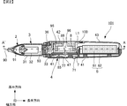
- FIG. 1 is a plan sectional view of the inhaler 101 according to the first embodiment as viewed from the top side.
- FIG. 2 is a side sectional view of the inhaler 101 according to the first embodiment viewed from the side.
- FIG. 3 is an external perspective view of the piezoelectric blower 8 and the circuit board 7 shown in FIG. 4 is an exploded perspective view of the piezoelectric blower 8 and the circuit board 7 shown in FIG.
- FIG. 1 shows a cross-section at the position indicated by the alternate long and short dash line A-A ′ in FIG. 2.
- the arrows in FIG. 1 indicate the gas flow.
- FIG. 2 shows a cross-section at the position indicated by the alternate long and short dash line B-B ′ in FIG. 1.
- the arrows in FIG. 2 indicate the gas flow.
- the inhaler 101 shown in FIGS. 1 and 2 is a liquid inhaler such as a runny nose here.
- the inhaler 101 has a long shape having a longitudinal direction as a whole, and is used with one of the longitudinal directions (hereinafter referred to as the front) directed toward a patient or the like.
- the inhaler 101 has a width direction and a thickness direction orthogonal to the longitudinal direction, and is configured to be thin and thinner in the thickness direction than in the width direction.
- the suction device 101 includes a nozzle 2, a separator 3, and a housing 4.
- the nozzle 2, the separator 3, and the housing 4 are arranged in the order of description from the front to the rear in the longitudinal direction.
- the nozzle 2 is inserted into a nasal cavity of a patient or the like when the inhaler 101 is used, and inhales fluid such as a runny nose.
- the separator 3 separates and stores a mixture such as nasal fluid contained in the fluid sucked by the nozzle 2 when the inhaler 101 is used.
- the gas from which the mixture is separated from the fluid (air in this embodiment) is sucked from the separator 3 into the housing 4.
- the housing 4 is gripped by an operator or the like during use.
- the inhaler 101 includes a battery unit 6, a circuit board 7, and a piezoelectric blower 8 as built-in components of the housing 4.
- the battery unit 6 includes a battery 61 and a battery case 62.
- the battery case 62 holds the battery 61 in a replaceable manner.
- the circuit board 7 constitutes a power supply circuit and the like, and includes a power switch 71.
- the power switch 71 is exposed to the outside through an opening provided in the housing 4.
- the circuit board 7 turns the power supply from the battery unit 6 to the piezoelectric blower 8 on or off according to the pressed state of the power switch 71.
- the piezoelectric blower 8 generates a negative pressure in the flow path in the housing 4 and sucks gas from the separator 3 into the housing 4.
- the nozzle 2 is made of an integral elastic material.
- the outer shape of the nozzle 2 is inclined so as to become thinner toward the front.
- the nozzle 2 is provided with a suction port 90 and a flow path 91.
- the suction port 90 is an opening that is provided at the front end of the nozzle 2 and sucks an external fluid including a runny nose.
- the flow path 91 is provided so as to penetrate the inside of the nozzle 2 in the longitudinal direction, and communicates with the suction port 90.
- the nozzle 2 is connected to the front side of the separator 3 in an airtight state and can be detached from the separator 3.
- the separator 3 includes a case part 31, a cylindrical part 32, a cap part 33, and a cylindrical part 34.
- the case part 31 is a box-shaped member that opens rearward.
- the cylindrical portion 32 is a cylindrical portion attached to the case portion 31, protrudes forward from the front surface of the case portion 31, and extends rearward from the inner bottom surface of the case portion 31.
- the nozzle 2 is fitted to the front end of the cylindrical portion 32.
- the cap portion 33 is a lid-like member that fits behind the case portion 31.
- the cylindrical part 34 is a cylindrical part attached to the cap part 33 and extends forward from the cap part 33.
- the separator 3 is provided with flow paths 92, 93, 94.
- the flow path 92 is provided so as to penetrate the inside of the cylindrical portion 32 in the longitudinal direction and communicate with the flow path 91 of the nozzle 2.
- the flow path 93 is provided inside the case portion 31 and communicates with the flow path 92 of the cylindrical portion 32.
- the flow path 94 is provided so as to penetrate the inside of the cylindrical portion 34 in the longitudinal direction, and communicates with the flow path 93 of the case portion 31.
- the cylindrical portion 32 and the cylindrical portion 34 are arranged so as to alternate in the longitudinal direction inside the case portion 31, and the flow channel 92 and the flow channel 94 communicate with each other through the flow channel 93.
- liquid such as runny nose contained in the fluid led from the nozzle 2 to the separator 3 is difficult to leak from the inside of the case portion 31 (flow path 93), and only the gas contained in the fluid is separated from the separator 3. Sucked into the housing 4.
- a concave portion 35 is provided on the rear surface of the cap portion 33.
- the separator 3 is connected to the front side of the housing 4 in an airtight state by fitting the housing 4 into the recess 35.
- a filter 36 is provided on the inner bottom surface of the recess 35.
- the filter 36 is a non-woven paper-like or sponge-like film body and has a function of preventing liquid such as runny nose from leaking from the separator 3 side to the housing 4 side. Note that the filter 36 is not necessarily provided.
- the separator 3 is connected to the housing 4 by a screw 37 and can be separated from the housing 4 by removing the screw 37. Further, the case portion 31 and the cap portion 33 can also be divided by removing the screw 37.
- each part may be connected so that isolation
- the housing 4 includes a lower housing 41, an upper housing 42, and a battery cover 43.
- the lower housing 41 has a thin box shape with an opening on the top side in the thickness direction.
- the upper housing 42 has a thin box shape with an opening on the bottom surface side in the thickness direction.
- the upper housing 42 is connected to the lower housing 41 so as to form a container shape. For this reason, the lower casing 41, the battery cover 43, and a part of the upper casing 42 constitute an internal space 100. In the internal space 100, the battery unit 6, the circuit board 7, and the piezoelectric blower 8 are accommodated.
- the lower housing 41 is provided with an opening on the top surface side so that the battery 61 of the battery unit 6 can be replaced.
- the battery cover 43 covers the opening of the lower housing 41 so as to cover the opening. Is attached.
- the lower housing 41 is provided with an exhaust port 47, the details of which will be described later.
- the internal space 100 communicates with the external space of the housing 4 through the joint portion between the upper housing 42 and the battery cover 43 and the exhaust port 47 and is equal to the external air pressure.
- the lower casing 41 and the upper casing 42 support the circuit board 7 in the internal space 100.
- a flow path 95 and a flow path 96 are provided inside the upper housing 42.
- the flow path 95 communicates with the flow path 94 of the separator 3.
- the flow path 95 extends from the portion communicating with the flow path 94 to the inner side of the upper housing 42 in the longitudinal direction, bends in an inverted U shape in the middle, and communicates with the flow path 96.
- the flow path 96 is cylindrical and communicates with the suction hole 89 of the piezoelectric blower 8.
- the piezoelectric blower 8 has a plate shape, and is joined to the upper housing 42 so that the flow path 95 and the flow path 96 are hermetically sealed.
- the piezoelectric blower 8 has a suction hole 89 that opens near the center of the top surface of the piezoelectric blower 8 and a discharge hole 99 that opens at the center of the bottom surface of the piezoelectric blower 8.
- the piezoelectric blower 8 is mounted on the first main surface (one main surface) on the upper housing 42 side of the circuit board 7.
- the circuit board 7 is connected to the battery 61 via the power line L1.
- a power feeding pattern 78 is mounted on the first main surface of the circuit board 7.
- a plurality of electronic components 85 are mounted on the second main surface (the other main surface) on the lower housing 41 side of the circuit board 7.
- the circuit board 7 generates a drive voltage from the power supply voltage of the battery 61. Then, the circuit board 7 drives the piezoelectric blower 8 by applying a driving voltage to the piezoelectric blower 8.
- the circuit board 7 has a through-hole 77 facing the discharge hole 99.
- the through-hole 77 overlaps the discharge hole 99 among the suction hole 89 and the discharge hole 99 when the first main surface of the circuit board 7 is viewed from the front.
- the through-hole 77 is wider than the discharge hole 99 and includes the discharge hole 99 when the first main surface of the circuit board 7 is viewed from the front.
- the piezoelectric blower 8 sucks gas from the flow path 96 through the suction hole 89 and passes through the discharge hole 99 through the through-hole 77 to the internal space. 100 is discharged. The gas discharged from the discharge hole 99 is discharged from the exhaust port 47. As a result, a negative pressure is generated in the channel 96.
- the flow path 95 of the housing 4 the flow paths 94, 93, 92 of the separator 3, and the flow path 91 of the nozzle 2 are caused by the negative pressure generated in the flow path 96 in the housing 4.
- a fluid flow occurs, and external fluid is sucked from the suction port 90 of the nozzle 2.
- suction port 90 corresponds to the first opening of the present invention.
- the exhaust port 47 corresponds to the second opening of the present invention.
- the channel 96, the channel 95, the channel 94, the channel 93, the channel 92, and the channel 91 correspond to the first channel of the present invention.
- the internal space 100 corresponds to the second flow path of the present invention.
- the portion of the upper housing 42 that constitutes the nozzle 2, the separator 3, the flow channel 96, and the flow channel 95 corresponds to the first housing of the present invention.
- the lower casing 41, the battery cover 43, and the upper casing 42 constituting the internal space 100 correspond to the second casing of the present invention.
- FIG. 5 is an enlarged side sectional view showing the periphery of the piezoelectric blower 8.
- the piezoelectric blower 8 includes a piezoelectric element 81, a structure 82, and an electrode terminal 88.
- the structure 82 has a disk shape.
- a suction hole 89 is opened near the center of the top surface of the structure 82.
- a discharge hole 99 is opened at the center of the bottom surface of the structure 82.
- a flow path 97 and a pump chamber 98 are provided inside the structure 82.
- the flow path 97 communicates with the suction hole 89 and the discharge hole 99.
- the pump chamber 98 is a thin cylindrical space and communicates with a part of the flow path 97 facing the discharge hole 99.
- the pump chamber 98 constitutes a part of the flow path in the suction device 101 together with the flow path 97.
- the structure 82 is made of, for example, stainless steel (SUS).
- the inner top surface of the pump chamber 98 in the structure 82 is configured as a diaphragm 83 capable of bending vibration.
- the diaphragm 83 has a disc shape, the bottom surface faces the pump chamber 98, and the piezoelectric element 81 is attached to the top surface.
- the bottom surface of the diaphragm 83 faces the discharge hole 99 with the pump chamber 98 interposed therebetween.
- the piezoelectric element 81 is made of, for example, lead zirconate titanate ceramic.
- the piezoelectric element 81 has a thin disk shape in the thickness direction, and has piezoelectricity that tends to expand and contract in the surface direction of the piezoelectric element 81 when an AC driving voltage is applied from the circuit board 7.
- Electrodes are provided on both main surfaces of the piezoelectric element 81.
- the electrodes on both main surfaces of the piezoelectric element 81 are connected to the electrode terminal 88.
- the electrode terminal 88 is bonded to the power supply pattern 78 of the circuit board 7.
- FIG. 6 is a schematic diagram showing a vibration mode of the piezoelectric blower 8.
- the arrows in FIG. 6 indicate the gas flow.
- the piezoelectric element 81 and the diaphragm 83 are attached to each other to form a unimorph structure.
- an alternating drive voltage is applied to both electrodes of the piezoelectric element 81 from the circuit board 7 via the electrode terminal 88, the piezoelectric element 81 expands and contracts. Then, the piezoelectric element 81 and the diaphragm 83 periodically flex and vibrate concentrically as shown in FIGS. 6B and 6C due to the expansion and contraction of the piezoelectric element 81.
- the piezoelectric element 81 when the piezoelectric element 81 is about to extend from the stationary state shown in FIG. 6A, the diaphragm 83 is moved to the piezoelectric element 81 side (bottom side) as shown in FIG. 6B.
- the volume of the pump chamber 98 is increased by being bent convexly.
- negative pressure is generated in the pump chamber 98, the negative pressure is transmitted to the flow path 97 communicating with the pump chamber 98, and the fluid in the flow path 97 is sucked into the pump chamber 98.
- the vibration plate 83 is convexly bent toward the pump chamber 98 side (top surface side), and the volume of the pump chamber 98 decreases.
- the gas in the pump chamber 98 is discharged from the discharge hole 99 to the outside (internal space 100) through the through-hole 77, and is drawn into the gas flow so that the gas in the flow path 97 is discharged from the discharge hole 99. It is discharged to the outside (internal space 100) through the through-hole 77.
- the gas discharged into the internal space 100 is discharged from the exhaust port 47 to the outside of the housing 4 (see FIG. 2).
- the suction device 101 allows the gas discharged from the piezoelectric blower 8 to pass through the through-hole 77 of the circuit board 7. Therefore, the inhaler 101 can arrange the piezoelectric blower 8 in the vicinity of the circuit board 7 or on the circuit board 7.
- circuit board 7 and the piezoelectric blower 8 can be arranged to overlap each other, it is not necessary to arrange the circuit board 907 and the piezoelectric blower 8 in the longitudinal direction like the inhaler 901 shown in FIG.
- the size of the device main body can be reduced.
- the inhaler 101 has the piezoelectric blower 8 mounted directly on the circuit board 7. Therefore, the inhaler 101 can compensate for a decrease in strength due to the through-hole 77 provided in the circuit board 7 and can further improve the strength.
- the piezoelectric blower 8 has an electrode terminal 88 that is joined to the power supply pattern 78.
- the suction device 101 can omit the power supply line L2 (see FIG. 17) that connects the piezoelectric blower 8 and the circuit board 7. Thereby, simplification of a structure, space reduction, and cost reduction are realizable.
- the through-hole 77 is wider than the hole and includes a hole when the one main surface of the circuit board 7 is viewed from the front.
- the suction device 101 can prevent the suction force of the piezoelectric blower 8 from being lowered.
- FIG. 7 is a side cross-sectional view of an inhaler 201 according to the second embodiment of the present invention.
- FIG. 8 is an exploded perspective view of the piezoelectric blower 8 and the circuit board 7 shown in FIG.
- FIG. 7 is a schematic diagram, and detailed illustration is omitted for the sake of simplicity.
- the arrows in FIG. 7 indicate the gas flow.
- the difference between the inhaler 201 according to the second embodiment and the inhaler 101 is the arrangement of the circuit board 7 and the piezoelectric blower 8. Since the other points are the same as those of the inhaler 101, description thereof is omitted.
- the piezoelectric blower 8 is mounted on the first main surface (one main surface) of the circuit board 7.
- the through hole 77 of the circuit board 7 faces the suction hole 89.
- the through-hole 77 overlaps the suction hole 89 when the first main surface of the circuit board 7 is viewed from the front.
- the electrode terminal 88 of the piezoelectric blower 8 is bonded to the power supply pattern 78 of the circuit board 7.
- the suction device 201 allows the gas sucked into the piezoelectric blower 8 to pass through the through hole 77 of the circuit board 7. Therefore, the inhaler 201 can place the piezoelectric blower 8 in the vicinity of the circuit board 7 or on the circuit board 7.
- the circuit board 7 and the piezoelectric blower 8 can be arranged in an overlapping manner, it is not necessary to arrange the circuit board 7 and the piezoelectric blower 8 in the longitudinal direction as in the inhaler 901 shown in FIG.
- the size of the apparatus main body can be reduced as in the inhaler 101.
- FIG. 9 is a side cross-sectional view of an inhaler 301 according to the third embodiment of the present invention.
- FIG. 9 is a schematic diagram, and detailed illustration is omitted for the sake of simplicity.
- the arrows in FIG. 9 indicate the gas flow.
- the difference between the inhaler 301 according to the third embodiment and the inhaler 101 is the arrangement of the circuit board 7 and the piezoelectric blower 8.
- the inhaler 301 includes a thick separator 303 and a housing 304 in accordance with the arrangement of the circuit board 7 and the piezoelectric blower 8. Since the other points are the same as those of the inhaler 101, description thereof is omitted.
- the piezoelectric blower 8 is mounted on the first main surface (one main surface) of the circuit board 7.
- the through hole 77 of the circuit board 7 faces the discharge hole 99. Further, the through-hole 77 overlaps the discharge hole 99 among the suction hole 89 and the discharge hole 99 when the first main surface of the circuit board 7 is viewed from the front.
- the through-hole 77 is wider than the discharge hole 99 and includes the discharge hole 99 when the first main surface of the circuit board 7 is viewed from the front.
- the inhaler 301 allows the gas discharged from the piezoelectric blower 8 to pass through the through-hole 77 of the circuit board 7. Therefore, the inhaler 301 can arrange the piezoelectric blower 8 in the vicinity of the circuit board 7 or on the circuit board 7.
- the circuit board 7 and the piezoelectric blower 8 can be arranged so as to overlap each other, so that it is not necessary to arrange the circuit board 907 and the piezoelectric blower 8 side by side in the longitudinal direction like the inhaler 901 shown in FIG.
- the size of the apparatus main body can be reduced as in the inhaler 101.
- the length in the longitudinal direction can be shorter than that of the inhaler 101.
- the circuit board 7 and the piezoelectric blower 8 are arranged so that the discharge hole 99 and the through-hole 77 of the circuit board 7 face the battery. That is, the circuit board 7 and the piezoelectric blower 8 are arranged so that the gas discharged from the discharge hole 99 through the through-hole 77 of the circuit board 7 hits the battery. Thereby, the inhaler 301 can further cool the battery 61.
- FIG. 10 is a side sectional view of the main part of an inhaler 401 according to the fourth embodiment of the present invention.
- FIG. 10 is a schematic diagram, and detailed illustration is omitted for simplification of explanation.
- the arrows in FIG. 10 indicate the gas flow.
- suction device 401 according to the fourth embodiment and the suction device 101 is that a housing 404 that does not have the exhaust port 47 is provided. Since the other points are the same as those of the inhaler 101, description thereof is omitted.
- the inhaler 401 since the housing 404 does not have the exhaust port 47, the gas discharged from the discharge hole 99 through the through-hole 77 of the circuit board 7 hits the housing 404, and the second main surface of the circuit board 7 It flows in the direction of the surface. Thereby, the inhaler 401 can further cool the plurality of electronic components 85 on the circuit board 7.
- FIG. 11 is a side sectional view of a main part of an inhaler 501 according to the fifth embodiment of the present invention.
- FIG. 11 is a schematic diagram, and detailed illustration is omitted for simplification of explanation.
- the arrows in FIG. 11 indicate the gas flow.
- the difference of the inhaler 501 according to the fifth embodiment from the inhaler 101 is that a cover 504 is provided.
- the cover 504 is attached to the circuit board 7 by a support portion 505.
- the support portion 505 has a vent hole 506. Since the other points are the same as those of the inhaler 101, description thereof is omitted.
- the inhaler 501 includes the cover 504, the gas discharged from the discharge hole 99 through the through-hole 77 of the circuit board 7 hits the cover 504 and flows in the surface direction of the second main surface of the circuit board 7. Thereby, the inhaler 501 can further cool the plurality of electronic components 85 on the circuit board 7.
- FIG. 12 is a side sectional view of an inhaler 601 according to the sixth embodiment of the present invention.
- FIG. 13 is an external perspective view of the piezoelectric blower 8 and the circuit board 607 shown in FIG. 14 is an external perspective view of the main part of the housing 604 shown in FIG.
- FIG. 12 is a schematic diagram, and detailed illustration is omitted for the sake of simplicity.
- the arrows in FIG. 12 indicate the gas flow.
- the main difference between the inhaler 601 according to the sixth embodiment and the inhaler 101 is a circuit board 607 and a housing 604.
- the circuit board 607 is longer in the longitudinal direction than the circuit board 7 of the inhaler 101.
- the plurality of electronic components 85 and the piezoelectric blower 8 are mounted on the same surface of the circuit board 607.
- the casing 604 is elongated in the longitudinal direction in accordance with the length of the circuit board 607 in the longitudinal direction.
- the housing 604 does not have the exhaust port 47 but has a U-shaped projection 640 and a wall portion 641.
- the upper surface of the protrusion 640 is joined to the bottom surface of the piezoelectric blower 8.
- the separator 603 is also elongated in the longitudinal direction in accordance with the length of the housing 604 in the longitudinal direction.
- the piezoelectric blower 8 when driven, the piezoelectric blower 8 sucks gas from the suction hole 89 through the through-hole 77 and discharges the gas from the discharge hole 99 to the outside.
- the suction device 601 allows the gas sucked by the piezoelectric blower 8 to pass through the through hole 77 of the circuit board 607. Therefore, in the inhaler 601, the piezoelectric blower 8 can be disposed in the vicinity of the circuit board 607 or on the circuit board 607.
- the circuit board 607 and the piezoelectric blower 8 can be arranged so as to overlap each other, and therefore the circuit board 607 and the piezoelectric blower 8 do not have to be arranged in the longitudinal direction like the inhaler 901 shown in FIG.
- the size of the apparatus body can be reduced.
- the housing 604 does not have the exhaust port 47 but has a U-shaped projection 640 and a wall portion 641. Therefore, the gas discharged from the discharge hole 99 hits the protrusion 640 and the wall portion 641 and flows toward the plurality of electronic components 85 on the circuit board 607.
- the inhaler 601 can further cool the plurality of electronic components 85 on the circuit board 607.
- the inhaler 601 can make the thickness of the apparatus body thinner than the inhaler 101.
- FIG. 15 is a side sectional view of an inhaler 701 according to a seventh embodiment of the present invention.
- FIG. 15 is a schematic diagram, and detailed illustration is omitted for the sake of simplicity.
- the arrows in FIG. 15 indicate the gas flow.
- the difference of the inhaler 701 according to the seventh embodiment from the inhaler 101 is that a piezoelectric blower 28 is provided. Since the other points are the same as those of the inhaler 101, description thereof is omitted.
- the configuration of the piezoelectric blower 28 is the same as the configuration of the piezoelectric blower 8.
- the piezoelectric blower 8 and the piezoelectric blower 28 are laminated so that the discharge hole 99 of the piezoelectric blower 28 is connected to the suction hole 89 of the piezoelectric blower 8. That is, the piezoelectric blower 28 is arranged in series with the piezoelectric blower 8.
- the electrode terminal 88 of the piezoelectric blower 28 is connected to the power feeding pattern of the circuit board 7.
- the piezoelectric blower 8 is mounted on the first main surface (one main surface) on the upper housing 42 side of the circuit board 7.
- the through hole 77 of the circuit board 7 faces the discharge hole 99.
- the through-hole 77 overlaps the discharge hole 99 when the first main surface of the circuit board 7 is viewed from the front.
- the piezoelectric blower 28 sucks the gas from the suction hole 89 and discharges the gas from the discharge hole 99 when driven.
- the piezoelectric blower 8 discharges the gas discharged from the discharge hole 99 of the piezoelectric blower 28 to the outside of the suction device 701 through the through hole 77 and the exhaust port 47 of the circuit board 7 from the discharge hole 99.
- the inhaler 701 allows the gas discharged from the piezoelectric blower 8 to pass through the through-hole 77 of the circuit board 7. Therefore, the inhaler 701 can arrange the piezoelectric blowers 8 and 28 in the vicinity of the circuit board 7 or on the circuit board 7.
- the inhaler 701 can arrange the circuit board 7 and the piezoelectric blowers 8 and 28 so as to overlap with each other, unlike the inhaler 901 shown in FIG. 17, the circuit board 7 and the piezoelectric blowers 8 and 28 are not arranged side by side in the longitudinal direction. It's good enough.
- the size of the apparatus body can be reduced.
- the suction device 701 can increase the maximum suction pressure twice as compared with the case where one piezoelectric blower 8 is arranged.
- n 2 that is, the two piezoelectric blowers 8 and 28 are arranged in series, but the present invention is not limited to this. In implementation, if n ⁇ 3, that is, three or more piezoelectric blowers may be arranged in series. In this case, the maximum discharge flow rate can be increased n times.
- FIG. 16 is a side sectional view of an inhaler 801 according to the eighth embodiment of the present invention.
- FIG. 16 is a schematic diagram, and detailed illustration is omitted for the sake of simplicity.
- the arrows in FIG. 16 indicate the gas flow.
- the difference between the inhaler 801 according to the eighth embodiment and the inhaler 601 is that the inhaler 801 and the piezoelectric blower 28 are provided, but the protrusion 640 is not provided. Since the other points are the same as those of the inhaler 601, description thereof is omitted.
- the configuration of the piezoelectric blower 28 is the same as the configuration of the piezoelectric blower 8.
- the piezoelectric blower 28 is mounted on the same first main surface (one main surface) as the piezoelectric blower 8 of the circuit board 607.
- the circuit board 607 has a through hole 877.
- the through hole 877 of the circuit board 607 faces the suction hole 89.
- the through-hole 877 overlaps the suction hole 89 when the first main surface of the circuit board 607 is viewed from the front.
- the electrode terminal 88 of the piezoelectric blower 28 is bonded to the power supply pattern of the circuit board 607.
- the piezoelectric blower 8 is mounted on the first main surface (one main surface) of the circuit board 607.
- the through hole 77 of the circuit board 607 faces the suction hole 89.
- the through-hole 77 overlaps the suction hole 89 when the first main surface of the circuit board 607 is viewed from the front.
- the piezoelectric blower 8 and the piezoelectric blower 28 are arranged in parallel.
- the piezoelectric blower 28 when driven, the piezoelectric blower 28 sucks gas from the suction hole 89 through the through-hole 877 and discharges the gas from the discharge hole 99 to the outside.
- the piezoelectric blower 8 sucks gas from the suction hole 89 through the through-hole 77 and discharges the gas from the discharge hole 99 to the outside.
- the inhaler 801 allows the gas sucked by the piezoelectric blowers 8 and 28 to pass through the through holes 77 and 877 of the circuit board 607. Therefore, the inhaler 801 can arrange the piezoelectric blowers 8 and 28 in the vicinity of the circuit board 607 or on the circuit board 607.
- the inhaler 801 can arrange the circuit board 607 and the piezoelectric blowers 8 and 28 so as to overlap each other, the circuit board 607 and the piezoelectric blowers 8 and 28 are not arranged side by side in the longitudinal direction like the inhaler 901 shown in FIG. It's good enough.
- the size of the apparatus body can be reduced.
- the suction device 801 can increase the maximum suction flow rate twice as compared with the case where one piezoelectric blower 8 is disposed.
- n 2 that is, the two piezoelectric blowers 8 and 28 are arranged in parallel and the circuit board 607 has the two through-holes 77 and 877.
- the present invention is not limited to this.
- n ⁇ 3 that is, three or more piezoelectric blowers may be arranged in parallel, and the circuit board may have three or more through holes (that is, the same number of through holes as the piezoelectric blowers). . In this case, the maximum suction flow rate can be increased n times.
- the shape of the nozzle 2 is not limited to the above example, and may be other shapes.
- the nozzle 2 may be configured in a funnel shape or a straw shape.
- the separator 3 may be configured to separate the gas contained in the fluid and the mixture (liquid) from structures other than those described above.
- a gas structure and a liquid contained in the fluid can be easily separated by adopting a valve structure for the separator 3.
- the structure of the piezoelectric blower 8 may be other than the above.
- the number of discharge side flow paths provided in the piezoelectric blower 8, the number of suction side flow paths, the respective paths, and the like can be appropriately changed.
- air is used as a gas, but the present invention is not limited to this.
- a gas other than air can be applied.
- the fluid to be inhaled is not limited to a liquid, and may be a solid or gel substance.
- the present invention can also be applied to a dust collecting device that collects minute dust or dust, a device that collects glue or adhesive applied to a workpiece, and the like.
Landscapes
- Health & Medical Sciences (AREA)
- Heart & Thoracic Surgery (AREA)
- Hematology (AREA)
- Engineering & Computer Science (AREA)
- Anesthesiology (AREA)
- Biomedical Technology (AREA)
- Vascular Medicine (AREA)
- Life Sciences & Earth Sciences (AREA)
- Animal Behavior & Ethology (AREA)
- General Health & Medical Sciences (AREA)
- Public Health (AREA)
- Veterinary Medicine (AREA)
- Reciprocating Pumps (AREA)
- External Artificial Organs (AREA)
Abstract
吸入装置(101)は、ノズル(2)とセパレータ(3)と筐体(4)とバッテリ部(6)と回路基板(7)と圧電ブロア(8)とを備えている。圧電ブロア(8)は、圧電ブロア(8)の天面の中央付近に開口する吸引孔(89)と、圧電ブロア(8)の底面の中心に開口する吐出孔(99)と、を有している。圧電ブロア(8)は、回路基板(7)の上筐体(42)側の第1主面上に実装されている。回路基板(7)は、圧電ブロア(8)に駆動電圧を印加して圧電ブロア(8)を駆動する。回路基板(7)は、吐出孔(99)と対向する貫通口(77)を有する。貫通口(77)は、回路基板(7)の第1主面を正面視したとき、吸引孔(89)および吐出孔(99)のうち、吐出孔(99)と重なる。貫通口(77)は、回路基板(7)の第1主面を正面視したとき、吐出孔(99)より広く、吐出孔(99)を含んでいる。
Description
本発明は、鼻水などの液体等を除去する際に利用される吸入装置に関する。
風邪や鼻炎、蓄膿症などにかかると、鼻水の分泌が過剰になることで鼻づまり等の症状が生じる。一般的には鼻をかむことで鼻づまりを解消することが可能であるが、自ら鼻をかむことができない乳幼児等の場合には、介助者が鼻水を除去する必要がある。
この際、ちり紙や綿棒を用いて少量の鼻水を除去することは可能であるが、多量の鼻水を除去することは難しかった。そこで、近年では、電動モータとポンプを用いて、鼻水を多量に除去できるようにした吸入装置が普及してきている(例えば特許文献1参照。)。
しかしながら、従来の吸入装置は、使用時に発生するモータ音や振動が大きく、乳幼児等がモータ音や振動に反応して体を動かして鼻水の吸引作業を行い難くなる場合があった。そこで、出願人は、電動モータに代えて、使用時に発生するモータ音や振動が小さい圧電素子を用いた吸入装置を開発している。
図17は、駆動源に圧電素子を用いた吸入装置901を模式的に示す図である。吸入装置901は、ノズル2とセパレータ3と筐体904とを備えている。さらに、吸入装置901は、筐体904内に、バッテリ61とバッテリケース62と回路基板907と圧電ブロア8と固定部10とを備えている。
固定部10には、円柱状の開口部11が設けられている。固定部10上には、圧電ブロア8が載置されている。
回路基板907は、電源線L1を介してバッテリ61に接続している。また、回路基板907は、給電線L2を介して圧電ブロア8に接続している。回路基板907には、複数の電子部品85が実装されている。回路基板907は、バッテリ61の電源電圧から駆動電圧を生成する。そして、回路基板907は、圧電ブロア8に駆動電圧を印加して圧電ブロア8を駆動する。
ノズル2は、吸入口90を有する。ノズル2は、鼻腔等に挿入され、外部の流体を吸入口90から吸引する。セパレータ3は、ノズル2の後端に接続して設けられている。セパレータ3の内部は、ノズル2の内部を介して吸入口90に通じている。セパレータ3は、ノズル2で吸引した鼻水を空気から分離する。筐体904は、セパレータ3の内部に通じる流路95及び流路96を構成している。また、筐体904には気体の排気口47が設けられている。
圧電ブロア8は、セパレータ3の後端に接続して設けられている。圧電ブロア8は、気体の吸引孔89と気体の吐出孔99と圧電素子と振動板とを備えている。圧電素子は、振動板に貼付されている。圧電素子は、駆動により振動板を屈曲振動させる。これにより、圧電ブロア8は、セパレータ3が分離した流路96の空気を吸引孔89から吸引し、吐出孔99から吐出する。吐出孔99から吐出された空気は、排気口47から筐体904の外部に排出される。
このような構成の吸入装置901では、圧電素子の駆動に摺動や摩擦が伴うことがなく、駆動音や振動を大幅に抑制することができる。
しかしながら、吸入装置901の構造では、ノズル2、セパレータ3、圧電ブロア8、回路基板907、及びバッテリ61が長手方向に並んでいる。そのため、近年の吸入装置では装置本体のサイズの一層の小型化が求められているにも係らず、吸入装置901では、長手方向の長さが長いという問題がある。
そこで、本発明の目的は、装置本体のサイズを小型化できる吸入装置を提供することにある。
本発明の吸入装置は、気体の吸引孔と気体の吐出孔と駆動源としての圧電素子とを有する圧電ブロアと、
吸引孔または吐出孔と対向する貫通口を有し、圧電素子に駆動電圧を印加して圧電ブロアを駆動する回路基板と、を備えている。
吸引孔または吐出孔と対向する貫通口を有し、圧電素子に駆動電圧を印加して圧電ブロアを駆動する回路基板と、を備えている。
そして、貫通口は、回路基板の一方主面を正面視したとき、吸引孔および吐出孔のうち、対向する方の孔と重なる。
この構成において、駆動電圧が回路基板から圧電素子に印加されると、圧電素子が伸縮する。そして、圧電ブロアは、圧電素子の伸縮力によって駆動する。これにより、圧電ブロアは、気体を回路基板の貫通口を介して吸引孔から吸引し、吐出孔から気体を吐出する。又は、圧電ブロアは、気体を吸引孔から吸引し、吐出孔から回路基板の貫通口を介して気体を吐出する。
この構成の吸入装置は、圧電ブロアに吸引される気体、又は圧電ブロアから吐出される気体を、回路基板の貫通口から通過させている。そのため、この構成の吸入装置は、圧電ブロアを回路基板の近傍または回路基板上に配置することができる。
すなわち、この構成の吸入装置は、回路基板および圧電ブロアを重ねて配置できるため、図17に示す吸入装置901のように回路基板および圧電ブロアを並べて配置しなくとも済む。
したがって、この構成の吸入装置によれば、吸入装置本体のサイズを小型化できる。
また、吐出孔から回路基板の貫通口を介して吐出される気体を、回路基板またはバッテリ等にあてることで、回路基板またはバッテリ等を冷却することもできる。
また、圧電ブロアは、回路基板の一方主面上に実装されていることが好ましい。
この構成では、回路基板上に圧電ブロアを直接実装することで、回路基板に設けた貫通口による強度低下を補い、更なる強度向上を図ることができる。
また、回路基板の一方主面上には、駆動電圧を供給するための給電パターンが設けられ、圧電ブロアは、給電パターンに接合する電極端子を有することが好ましい。
この構成では、圧電ブロアと回路基板とを接続する給電線を省略できる。これにより、構成の簡略化、低スペース化、及び低コスト化を実現できる。
また、貫通口は、回路基板の一方主面を正面視したとき、孔より広く、孔を含んでいることが好ましい。
この構成では、圧電ブロアから吐出される気体の全ては、貫通口を通過する。すなわち、圧電ブロアから吐出される気体が回路基板にあたって阻害されない。
したがって、この構成によれば、圧電ブロアの吸引力が低下することを防止できる。
また、吸入装置は、圧電ブロア及び回路基板を収納する筐体を備えることが好ましい。そして、筐体は、第1流路を介して吸引孔に連通し、筐体の外部に露出する第1開口部と、第2流路を介して吐出孔に連通し、筐体の外部に露出する第2開口部と、を有することが好ましい。
筐体は、第1開口部を有する第1筐体と、第2開口部を有する第2筐体と、から構成されることが好ましい。
本発明によれば、吸入装置本体のサイズを小型化できる。
以下、本発明の第1の実施形態に係る吸入装置について図を用いて説明する。
図1は、第1の実施形態に係る吸入装置101を天面側から視た平面断面図である。図2は、第1の実施形態に係る吸入装置101を側面側から視た側面断面図である。図3は、図2に示す圧電ブロア8及び回路基板7の外観斜視図である。図4は、図2に示す圧電ブロア8及び回路基板7の分解斜視図である。
なお、図1は、図2中に一点鎖線A-A’で示す位置の断面を示している。図1中の矢印は、気体の流れを示している。図2は、図1中に一点鎖線B-B’で示す位置の断面を示している。図2中の矢印は、気体の流れを示している。
図1および図2に示す吸入装置101は、ここでは鼻水等の液体吸入装置である。該吸入装置101は、全体として長手方向を有する長尺な形状であり、長手方向の一方(以下、前方と称する。)を患者等に向けて使用される。また、該吸入装置101は、長手方向に直交する幅方向と厚み方向とを有しており、厚み方向の寸法が幅方向の寸法よりも薄い薄型に構成されている。
吸入装置101の概略の構成は次のようなものである。吸入装置101は、ノズル2とセパレータ3と筐体4とを備えている。ノズル2、セパレータ3、および筐体4は、この記載順に長手方向の前方から後方にかけて並んでいる。
ノズル2は、吸入装置101の使用時に患者等の鼻腔に挿入され、鼻水等の流体を吸入する。セパレータ3は、吸入装置101の使用時にノズル2が吸引する流体に含まれる鼻水等の混合物を分離して貯留する。一方、流体から混合物が分離した気体(この実施形態では空気)は、セパレータ3から筐体4内へ吸引される。筐体4は、使用時に操作者等に把持される。
また、吸入装置101は、筐体4の内蔵部品としてバッテリ部6と回路基板7と圧電ブロア8とを備えている。バッテリ部6は、バッテリ61とバッテリケース62とを備えている。バッテリケース62は、バッテリ61を取り換え可能に保持している。
回路基板7は、給電回路等を構成しており、電源スイッチ71を備えている。電源スイッチ71は、筐体4に設けられた開口から外部に露出している。回路基板7は、電源スイッチ71の押下状態に応じてバッテリ部6から圧電ブロア8への給電をオンまたはオフする。
圧電ブロア8は、筐体4内の流路に負圧を生じさせ、セパレータ3から筐体4内に気体を吸引する。
以下に、各部の詳細な構成について説明する。
ノズル2は、一体の弾性材料からなる。ノズル2は、前方ほど細くなるように外形に傾斜がついている。そして、ノズル2には、吸入口90と流路91とが設けられている。吸入口90は、ノズル2の前方端に設けられた、鼻水等を含む外部の流体を吸入する開口である。
流路91は、ノズル2の内側を長手方向に貫通して設けられており、吸入口90に通じている。このノズル2は、セパレータ3の前方側に気密した状態で連結されており、セパレータ3から取り外し可能になっている。
セパレータ3は、ケース部31と筒状部32とキャップ部33と筒状部34とを備えている。ケース部31は、後方に開口する箱状の部材である。筒状部32は、ケース部31に付設された筒状の部位であり、ケース部31の前方面から前方に突出し、ケース部31の開口内底面から後方に伸びている。
筒状部32の前方端には、ノズル2が嵌め合わされている。キャップ部33は、ケース部31の後方に嵌め合わされる蓋状の部材である。筒状部34は、キャップ部33に付設された筒状の部位であり、キャップ部33から前方に伸びている。
また、セパレータ3には流路92,93,94が設けられている。流路92は、筒状部32の内側を長手方向に貫通して設けられており、ノズル2の流路91に通じている。流路93は、ケース部31の内側に設けられており、筒状部32の流路92と通じている。流路94は、筒状部34の内側を長手方向に貫通して設けられており、ケース部31の流路93と通じている。
筒状部32と筒状部34とは、ケース部31の内部で長手方向に互い違いになるように配置され、流路93を介して流路92と流路94とは通じている。このことによってノズル2からセパレータ3に導かれた流体に含まれる鼻水等の液体は、ケース部31の内部(流路93)から漏出し難くなっており、流体に含まれる気体のみがセパレータ3から筐体4内へ吸引される。
キャップ部33の後方面には凹部35が設けられている。このセパレータ3は、この凹部35に筐体4を嵌め込むことで、筐体4の前方側に気密した状態で連結されている。凹部35の内底面にはフィルタ36が設けられている。
フィルタ36は、不織紙状やスポンジ状の膜体であり、セパレータ3側から筐体4側に鼻水等の液体が漏出することを防ぐ機能を有している。なお、フィルタ36は必ずしも設けなくても良い。
また、セパレータ3は、ねじ37によって筐体4と連結されており、ねじ37を外すことによって筐体4から分離可能となっている。また、ケース部31とキャップ部33との間も、ねじ37を外すことによって分割可能となっている。
このため、セパレータ3からの鼻水の除去と洗浄が可能である。各部の連結部分には気密のために適宜オーリングを設けている。なお、各部は、ねじ37の他の連結手段を用いて分離可能に連結されていてもよく、各々が一体に構成されていてもよい。
筐体4は、下筐体41と上筐体42とバッテリカバー43とによって構成されている。下筐体41は、厚み方向の天面側に開口が開いた薄手の箱状である。上筐体42は、厚み方向の底面側に開口が開いた薄手の箱状である。
上筐体42は、容器状となるように下筐体41に連結されている。このため、下筐体41、バッテリカバー43、及び上筐体42の一部は、内部空間100を構成している。内部空間100には、バッテリ部6と回路基板7と圧電ブロア8とが収納されている。
下筐体41には、バッテリ部6のバッテリ61を取り換え可能にするための開口が天面側に設けられており、バッテリカバー43は、当該開口を覆うように下筐体41の天面側に取り付けられている。下筐体41には、詳細を後述する排気口47が設けられている。内部空間100は、上筐体42とバッテリカバー43との継ぎ目部分や排気口47を介して筐体4の外部空間と通じ外気圧と等しくなっている。
下筐体41と上筐体42とは、内部空間100において回路基板7を支持している。
また、上筐体42の内側には、流路95及び流路96が設けられている。流路95は、セパレータ3の流路94に通じている。流路95は、流路94と通じている箇所から上筐体42の内側を長手方向の後方に延び、途中で逆U字状に屈曲し、流路96に通じている。流路96は、円柱状であり、圧電ブロア8の吸引孔89に通じている。
圧電ブロア8は、板状であり、流路95及び流路96を気密するように、上筐体42に接合されている。そして、圧電ブロア8は、圧電ブロア8の天面の中央付近に開口する吸引孔89と、圧電ブロア8の底面の中心に開口する吐出孔99と、を有している。圧電ブロア8は、回路基板7の上筐体42側の第1主面(一方主面)上に実装されている。
なお、圧電ブロア8と回路基板7の接合方法としては、例えば、接着剤による接着、両面テープによる固定、ネジによる締結、駆動回路上に設けた突起への篏合、スポット溶接、掘り込み部への嵌め合い等により行われる。
回路基板7は、電源線L1を介してバッテリ61に接続している。回路基板7の第1主面上には、給電パターン78が実装されている。回路基板7の下筐体41側の第2主面(他方主面)上には、複数の電子部品85が実装されている。回路基板7は、バッテリ61の電源電圧から駆動電圧を生成する。そして、回路基板7は、圧電ブロア8に駆動電圧を印加して圧電ブロア8を駆動する。
ここで、回路基板7は、吐出孔99と対向する貫通口77を有する。貫通口77は、回路基板7の第1主面を正面視したとき、吸引孔89および吐出孔99のうち、吐出孔99と重なる。貫通口77は、回路基板7の第1主面を正面視したとき、吐出孔99より広く、吐出孔99を含んでいる。
この吸入装置101では、電源スイッチ71がオンされて圧電ブロア8が駆動すると、圧電ブロア8は、流路96から気体を吸引孔89から吸引し、吐出孔99から貫通口77を介して内部空間100に気体を吐出する。吐出孔99から吐出された気体は、排気口47から排出される。これにより、流路96には負圧が発生することになる。
したがって、吸入装置101の全体としては、筐体4で流路96に発生する負圧によって、筐体4の流路95、セパレータ3の流路94,93,92、およびノズル2の流路91に流体の流れが生じ、ノズル2の吸入口90から外部の流体が吸引されることになる。
なお、吸入口90が、本発明の第1開口部に相当する。排気口47が、本発明の第2開口部に相当する。流路96,流路95,流路94,流路93,流路92、および流路91が、本発明の第1流路に相当する。内部空間100が、本発明の第2流路に相当する。ノズル2、セパレータ3、及び流路96,流路95を構成する上筐体42の部分が、本発明の第1筐体に相当する。下筐体41、バッテリカバー43、及び内部空間100を構成する上筐体42の部分が、本発明の第2筐体に相当する。
ここで、圧電ブロア8の詳細な構成について説明する。
図5は、圧電ブロア8の周辺を拡大して示す側面断面図である。圧電ブロア8は、圧電素子81と、構造体82と、電極端子88と、を備えている。構造体82は、円板状である。構造体82の天面の中央付近には、吸引孔89が開口している。また、構造体82の底面の中心には、吐出孔99が開口している。また、この構造体82の内側には、流路97とポンプ室98とが設けられている。
流路97は、吸引孔89及び吐出孔99に通じている。ポンプ室98は、薄い円柱状の空間であり、吐出孔99に面する流路97の一部に通じている。このポンプ室98は、流路97とともに吸入装置101における流路の一部を構成している。
構造体82は、例えばステンレススチール(SUS)から構成されている。構造体82におけるポンプ室98の内天面は、屈曲振動が可能な振動板83として構成されている。振動板83は円板状であり、底面がポンプ室98に面していて、天面に圧電素子81が貼付されている。振動板83の底面は、ポンプ室98を間に介して吐出孔99と対向している。
圧電素子81は、例えばチタン酸ジルコン酸鉛系セラミックスから構成されている。圧電素子81は、厚み方向に薄い円板状であり、交流の駆動電圧が回路基板7から印加されることで圧電素子81の面方向に伸縮しようとする圧電性を有している。
圧電素子81の両主面には、電極が設けられている。圧電素子81の両主面の電極は、電極端子88に接続している。電極端子88は、回路基板7の給電パターン78に接合している。
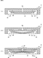
次に、圧電ブロア8の振動態様について説明する。図6は、圧電ブロア8の振動態様を示す模式図である。図6中の矢印は、気体の流れを示している。
圧電素子81と振動板83とは、互いに貼付されてユニモルフ構造を構成している。交流の駆動電圧が回路基板7から電極端子88を介して圧電素子81の両電極に印加されると、圧電素子81が伸縮する。そして、圧電素子81と振動板83とは、圧電素子81の伸縮によって図6(B)(C)に示すように周期的に同心円状に屈曲振動する。
具体的には、図6(A)に示す静止状態から圧電素子81が伸びようとする場合には、図6(B)に示すように、振動板83が圧電素子81側(底面側)に凸に屈曲してポンプ室98の体積が増大する。これにより、ポンプ室98に負圧が生じ、ポンプ室98に連通する流路97に負圧が伝わり、流路97の流体がポンプ室98に吸引される。
次に、圧電素子81が縮もうとすると、図6(C)に示すように、振動板83がポンプ室98側(天面側)に凸に屈曲してポンプ室98の体積が減少する。これにより、ポンプ室98の気体が吐出孔99から貫通口77を介して外部(内部空間100)に吐出されるとともに、その気体の流れに引き込まれて流路97内の気体が吐出孔99から貫通口77を介して外部(内部空間100)に吐出される。内部空間100に吐出された気体は、排気口47から筐体4の外部へ排出される(図2参照)。
このように、圧電ブロア8では、圧電素子81と振動板83との屈曲振動に伴い、ポンプ室98では周期的な体積変動と圧力変動とが繰り返し生じ、気体の流れに慣性力が働くようになる。これにより、流路97の流体が吐出孔99から吐出される気体の流れが定常的に生じるようになる。
この圧電ブロア8では、部材同士が摩擦(摺動)することが無いため、従来の電動モータ式の駆動部よりも、発生する駆動音や振動が小さい。したがって、吸入装置101から外部空間に漏れる圧電ブロア8の駆動音や振動は極めて小さなものになる。
また、吸入装置101は、圧電ブロア8から吐出される気体を、回路基板7の貫通口77から通過させている。そのため、吸入装置101は、圧電ブロア8を回路基板7の近傍または回路基板7上に配置することができる。
すなわち、吸入装置101は、回路基板7および圧電ブロア8を重ねて配置できるため、図17に示す吸入装置901のように回路基板907および圧電ブロア8を長手方向へ並べて配置しなくとも済む。
したがって、吸入装置101によれば、装置本体のサイズを小型化できる。
また、吸入装置101は、回路基板7上に圧電ブロア8を直接実装している。そのため、吸入装置101は、回路基板7に設けた貫通口77による強度低下を補い、更なる強度向上を図ることができる。
また、圧電ブロア8は、給電パターン78に接合する電極端子88を有している。
そのため、吸入装置101は、圧電ブロア8と回路基板7とを接続する給電線L2(図17参照)を省略できる。これにより、構成の簡略化、低スペース化、及び低コスト化を実現できる。
また、貫通口77は、回路基板7の一方主面を正面視したとき、孔より広く、孔を含んでいる。
そのため、吸入装置101では、圧電ブロア8から吐出される気体の全ては、貫通口77を通過する。すなわち、圧電ブロア8から吐出される気体が回路基板7にあたって阻害されない。
したがって、吸入装置101によれば、圧電ブロア8の吸引力が低下することを防止できる。
次に、本発明の第2の実施形態に係る吸入装置について説明する。
図7は、本発明の第2の実施形態に係る吸入装置201の側面断面図である。図8は、図7に示す圧電ブロア8及び回路基板7の分解斜視図である。
なお、図7は、模式図であり、説明簡略化のため詳細な図示を省略している。図7中の矢印は、気体の流れを示している。
第2の実施形態に係る吸入装置201が吸入装置101と相違する点は、回路基板7及び圧電ブロア8の配置である。その他の点は、吸入装置101と同じであるため、説明を省略する。
圧電ブロア8は、回路基板7の第1主面(一方主面)上に実装されている。回路基板7の貫通口77は、吸引孔89と対向する。貫通口77は、回路基板7の第1主面を正面視したとき、吸引孔89と重なる。なお、圧電ブロア8の電極端子88は、回路基板7の給電パターン78に接合している。
この構成において、圧電ブロア8は駆動時、気体を回路基板7の貫通口77を介して吸引孔89から吸引し、吐出孔99から気体を吐出する。
吸入装置201は、圧電ブロア8に吸引される気体を、回路基板7の貫通口77から通過させている。そのため、吸入装置201は、圧電ブロア8を回路基板7の近傍または回路基板7上に配置することができる。
すなわち、吸入装置201は、回路基板7および圧電ブロア8を重ねて配置できるため、図17に示す吸入装置901のように回路基板7および圧電ブロア8を長手方向へ並べて配置しなくとも済む。
したがって、吸入装置201によれば、吸入装置101と同様に、装置本体のサイズを小型化できる。
次に、本発明の第3の実施形態に係る吸入装置について説明する。
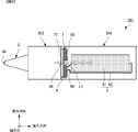
図9は、本発明の第3の実施形態に係る吸入装置301の側面断面図である。
なお、図9は、模式図であり、説明簡略化のため詳細な図示を省略している。図9中の矢印は、気体の流れを示している。
第3の実施形態に係る吸入装置301が吸入装置101と相違する点は、回路基板7及び圧電ブロア8の配置である。吸入装置301では、回路基板7及び圧電ブロア8の配置に併せて、厚みの厚いセパレータ303及び筐体304を備えている。その他の点は、吸入装置101と同じであるため、説明を省略する。
この実施形態においても、圧電ブロア8は、回路基板7の第1主面(一方主面)上に実装されている。回路基板7の貫通口77は、吐出孔99と対向する。また、貫通口77は、回路基板7の第1主面を正面視したとき、吸引孔89および吐出孔99のうち、吐出孔99と重なる。貫通口77は、回路基板7の第1主面を正面視したとき、吐出孔99より広く、吐出孔99を含んでいる。
吸入装置301は、圧電ブロア8から吐出される気体を、回路基板7の貫通口77から通過させている。そのため、吸入装置301は、圧電ブロア8を回路基板7の近傍または回路基板7上に配置することができる。
すなわち、吸入装置301は、回路基板7および圧電ブロア8を重ねて配置できるため、図17に示す吸入装置901のように回路基板907および圧電ブロア8を長手方向へ並べて配置しなくとも済む。
したがって、吸入装置301によれば、吸入装置101と同様に、装置本体のサイズを小型化できる。吸入装置301によれば、長手方向の長さを、吸入装置101より短くできる。
さらに、吸入装置301では、吐出孔99及び回路基板7の貫通口77がバッテリに向くよう、回路基板7及び圧電ブロア8が配置されている。すなわち、吐出孔99から回路基板7の貫通口77を介して吐出される気体がバッテリにあたるよう、回路基板7及び圧電ブロア8が配置されている。これにより、吸入装置301は、さらに、バッテリ61を冷却することができる。
次に、本発明の第4の実施形態に係る吸入装置について説明する。
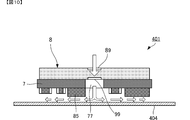
図10は、本発明の第4の実施形態に係る吸入装置401の主要部の側面断面図である。
なお、図10は、模式図であり、説明簡略化のため詳細な図示を省略している。図10中の矢印は、気体の流れを示している。
第4の実施形態に係る吸入装置401が吸入装置101と相違する点は、排気口47を有さない筐体404を備える点である。その他の点は、吸入装置101と同じであるため、説明を省略する。
吸入装置401では、筐体404が排気口47を有さないため、吐出孔99から回路基板7の貫通口77を介して吐出される気体が筐体404にあたり、回路基板7の第2主面の面方向へ流れる。これにより、吸入装置401は、さらに、回路基板7上の複数の電子部品85を冷却することができる。
次に、本発明の第5の実施形態に係る吸入装置について説明する。
図11は、本発明の第5の実施形態に係る吸入装置501の主要部の側面断面図である。
なお、図11は、模式図であり、説明簡略化のため詳細な図示を省略している。図11中の矢印は、気体の流れを示している。
第5の実施形態に係る吸入装置501が吸入装置101と相違する点は、カバー504を備える点である。カバー504は、支持部505によって回路基板7に取り付けられている。支持部505は、通気孔506を有する。その他の点は、吸入装置101と同じであるため、説明を省略する。
吸入装置501では、カバー504を備えるため、吐出孔99から回路基板7の貫通口77を介して吐出される気体がカバー504にあたり、回路基板7の第2主面の面方向へ流れる。これにより、吸入装置501は、さらに、回路基板7上の複数の電子部品85を冷却することができる。
次に、本発明の第6の実施形態に係る吸入装置について説明する。
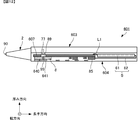
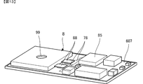
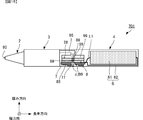
図12は、本発明の第6の実施形態に係る吸入装置601の側面断面図である。図13は、図12に示す圧電ブロア8及び回路基板607の外観斜視図である。図14は、図12に示す筐体604の主要部の外観斜視図である。
なお、図12は、模式図であり、説明簡略化のため詳細な図示を省略している。図12中の矢印は、気体の流れを示している。
第6の実施形態に係る吸入装置601が吸入装置101と主に相違する点は、回路基板607及び筐体604である。回路基板607は、吸入装置101の回路基板7より長手方向に長い。複数の電子部品85と圧電ブロア8とは、回路基板607の同一面上に実装されている。
また、筐体604は、回路基板607の長手方向の長さに併せて長手方向に長くなっている。筐体604は、排気口47を有さず、U字状の突起640及び壁部641を有している。突起640の上面は、圧電ブロア8の底面に接合している。セパレータ603も、筐体604の長手方向の長さに併せて長手方向に長くなっている。
なお、その他の吸入装置601の構成は、吸入装置101の構成と同じであるため、説明を省略する。
この構成において、圧電ブロア8は駆動時、貫通口77を介して気体を吸引孔89から吸引し、吐出孔99から外部に吐出する。
吸入装置601は、圧電ブロア8が吸引する気体を、回路基板607の貫通口77から通過させている。そのため、吸入装置601は、圧電ブロア8を回路基板607の近傍または回路基板607上に配置することができる。
すなわち、吸入装置601は、回路基板607および圧電ブロア8を重ねて配置できるため、図17に示す吸入装置901のように回路基板607および圧電ブロア8を長手方向へ並べて配置しなくとも済む。
したがって、吸入装置601によれば、吸入装置101と同様に、装置本体のサイズを小型化できる。
ここで、吸入装置601では筐体604が、排気口47を有さず、U字状の突起640及び壁部641を有している。そのため、吐出孔99から吐出される気体は、突起640及び壁部641にあたり、回路基板607上の複数の電子部品85側へ流れる。
これにより、吸入装置601は、さらに、回路基板607上の複数の電子部品85を冷却することができる。
また、複数の電子部品85と圧電ブロア8とが回路基板607の同一面上に実装されているため、吸入装置601は、装置本体の厚みを吸入装置101より薄くできる。
ここで、n個の圧電ブロアを直列または並列に配置した場合でも、吸入装置100と同様の効果を奏する。
まず、n個の圧電ブロアを直列に配置した場合について説明する。
図15は、本発明の第7の実施形態に係る吸入装置701の側面断面図である。
なお、図15は、n=2のときの図である。また、図15は、模式図であり、説明簡略化のため詳細な図示を省略している。図15中の矢印は、気体の流れを示している。
第7の実施形態に係る吸入装置701が吸入装置101と相違する点は、圧電ブロア28を備える点である。その他の点は、吸入装置101と同じであるため、説明を省略する。
圧電ブロア28の構成は、圧電ブロア8の構成と同じである。圧電ブロア28の吐出孔99が圧電ブロア8の吸引孔89に接続するよう、圧電ブロア8及び圧電ブロア28は積層されている。すなわち圧電ブロア28は、圧電ブロア8と直列に配置されている。なお、圧電ブロア28の電極端子88は、回路基板7の給電パターンに接続している。
そして、圧電ブロア8は、回路基板7の上筐体42側の第1主面(一方主面)上に実装されている。回路基板7の貫通口77は、吐出孔99と対向する。貫通口77は、回路基板7の第1主面を正面視したとき、吐出孔99と重なる。
この構成において、圧電ブロア28は駆動時、気体を吸引孔89から吸引し、吐出孔99から気体を吐出する。圧電ブロア8は駆動時、圧電ブロア28の吐出孔99から吐出された気体を、吐出孔99から回路基板7の貫通口77及び排気口47を介して吸入装置701の外部に吐出する。
吸入装置701は、圧電ブロア8が吐出する気体を、回路基板7の貫通口77から通過させている。そのため、吸入装置701は、圧電ブロア8、28を回路基板7の近傍または回路基板7上に配置することができる。
すなわち、吸入装置701は、回路基板7および圧電ブロア8、28を重ねて配置できるため、図17に示す吸入装置901のように回路基板7および圧電ブロア8、28を長手方向へ並べて配置しなくとも済む。
したがって、吸入装置701によれば、吸入装置101と同様に、装置本体のサイズを小型化できる。
また、吸入装置701では、2個の圧電ブロア8、28が直列に配置されている。そのため、吸入装置701は、圧電ブロア8を1個配置した場合と比べて最大吸引圧力を2倍に増加させることができる。
なお、吸入装置701では、n=2、すなわち2個の圧電ブロア8、28が直列に配置されているが、これに限るものではない。実施の際は、n≧3の場合、すなわち3個以上の圧電ブロアが直列に配置されていてもよい。この場合、最大吐出流量をn倍に増加させることができる。
次に、n個の圧電ブロアを並列に配置した場合について説明する。
図16は、本発明の第8の実施形態に係る吸入装置801の側面断面図である。
なお、図16は、n=2のときの図である。また、図16は、模式図であり、説明簡略化のため詳細な図示を省略している。図16中の矢印は、気体の流れを示している。
第8の実施形態に係る吸入装置801が吸入装置601と相違する点は、貫通口877及び圧電ブロア28を備え、突起640を備えない点である。その他の点は、吸入装置601と同じであるため、説明を省略する。
圧電ブロア28の構成は、圧電ブロア8の構成と同じである。圧電ブロア28は、回路基板607の圧電ブロア8と同じ第1主面(一方主面)上に実装されている。
また、回路基板607は、貫通口877を有する。回路基板607の貫通口877は、吸引孔89と対向する。貫通口877は、回路基板607の第1主面を正面視したとき、吸引孔89と重なる。なお、圧電ブロア28の電極端子88は、回路基板607の給電パターンに接合している。
また、圧電ブロア8は、回路基板607の第1主面(一方主面)上に実装されている。回路基板607の貫通口77は、吸引孔89と対向する。貫通口77は、回路基板607の第1主面を正面視したとき、吸引孔89と重なる。
すなわち、圧電ブロア8及び圧電ブロア28は、並列に配置されている。
この構成において、圧電ブロア28は駆動時、貫通口877を介して気体を吸引孔89から吸引し、吐出孔99から外部に吐出する。圧電ブロア8は駆動時、貫通口77を介して気体を吸引孔89から吸引し、吐出孔99から外部に吐出する。
吸入装置801は、圧電ブロア8、28が吸引する気体を、回路基板607の貫通口77、877から通過させている。そのため、吸入装置801は、圧電ブロア8、28を回路基板607の近傍または回路基板607上に配置することができる。
すなわち、吸入装置801は、回路基板607および圧電ブロア8、28を重ねて配置できるため、図17に示す吸入装置901のように回路基板607および圧電ブロア8、28を並べて長手方向へ配置しなくとも済む。
したがって、吸入装置801によれば、吸入装置101と同様に、装置本体のサイズを小型化できる。
また、吸入装置801では、2個の圧電ブロア8、28が並列に配置されている。そのため、吸入装置801は、圧電ブロア8を1個配置した場合と比べて最大吸引流量を2倍に増加させることができる。
なお、吸入装置801では、n=2、すなわち2個の圧電ブロア8、28が並列に配置され、回路基板607が2つの貫通口77、877を有しているが、これに限るものではない。実施の際は、n≧3の場合、すなわち3個以上の圧電ブロアが並列に配置され、回路基板が3個以上の貫通口(すなわち圧電ブロアと同数の貫通口)を有していてもよい。この場合、最大吸引流量をn倍に増加させることができる。
なお、前記各実施形態において、ノズル2の形状は、上述の例に限らず、他の形状であってもよい。例えば、母乳吸入装置や痰吸入装置として吸入装置101を用いる場合には、漏斗状やストロー状にノズル2を構成してもよい。
また、前記各実施形態にでは、セパレータ3において、流体に含まれる気体と混合物(液体)とを分離する構造は、上記以外の構造であってもよい。例えば、セパレータ3に弁構造を採用したりすることでも、流体に含まれる気体と液体とを容易に分離することができる。
また、前記各実施形態において、圧電ブロア8の構造も、上記以外の構造であってもよい。例えば、圧電ブロア8に設ける吐出側流路の数や、吸入側流路の数、それぞれの経路等を適宜に変更することができる。
また、前記各実施形態では気体として空気を用いているが、これに限るものではない。例えば、空気以外の気体であっても適用できる。
また、前記各実施形態において、吸入する対象となる流体は、液体に限られず、固体やゲル状の物質であってもよい。本発明は、微小な埃や粉塵を回収する集塵装置や、工作物に塗布しすぎた糊や接着剤を回収する装置などへの応用も可能である。
最後に、前記各実施形態の説明は、すべての点で例示であって、制限的なものではないと考えられるべきである。本発明の範囲は、上述の実施形態ではなく、特許請求の範囲によって示される。さらに、本発明の範囲には、特許請求の範囲と均等の意味および範囲内でのすべての変更が含まれることが意図される。
L1…電源線
L2…給電線
2…ノズル
3…セパレータ
4…筐体
6…バッテリ部
7…回路基板
8…圧電ブロア
10…固定部
11…開口部
28…圧電ブロア
31…ケース部
32…筒状部
33…キャップ部
34…筒状部
35…凹部
36…フィルタ
41…下筐体
42…上筐体
43…バッテリカバー
47…排気口
61…バッテリ
62…バッテリケース
71…電源スイッチ
77…貫通口
78…給電パターン
81…圧電素子
82…構造体
83…振動板
85…電子部品
88…電極端子
89…吸引孔
90…吸入口
91,92,93,94,95,96,97…流路
98…ポンプ室
99…吐出孔
100…内部空間
101…吸入装置
201…吸入装置
301…吸入装置
303…セパレータ
304…筐体
401…吸入装置
404…筐体
501…吸入装置
504…カバー
505…支持部
601…吸入装置
603…セパレータ
604…筐体
607…回路基板
640…突起
641…壁部
701…吸入装置
801…吸入装置
877…貫通口
901…吸入装置
904…筐体
907…回路基板
L2…給電線
2…ノズル
3…セパレータ
4…筐体
6…バッテリ部
7…回路基板
8…圧電ブロア
10…固定部
11…開口部
28…圧電ブロア
31…ケース部
32…筒状部
33…キャップ部
34…筒状部
35…凹部
36…フィルタ
41…下筐体
42…上筐体
43…バッテリカバー
47…排気口
61…バッテリ
62…バッテリケース
71…電源スイッチ
77…貫通口
78…給電パターン
81…圧電素子
82…構造体
83…振動板
85…電子部品
88…電極端子
89…吸引孔
90…吸入口
91,92,93,94,95,96,97…流路
98…ポンプ室
99…吐出孔
100…内部空間
101…吸入装置
201…吸入装置
301…吸入装置
303…セパレータ
304…筐体
401…吸入装置
404…筐体
501…吸入装置
504…カバー
505…支持部
601…吸入装置
603…セパレータ
604…筐体
607…回路基板
640…突起
641…壁部
701…吸入装置
801…吸入装置
877…貫通口
901…吸入装置
904…筐体
907…回路基板
Claims (6)
- 気体の吸引孔と前記気体の吐出孔と駆動源としての圧電素子とを有する圧電ブロアと、
前記吸引孔または前記吐出孔と対向する貫通口を有し、前記圧電素子に駆動電圧を印加して前記圧電ブロアを駆動する回路基板と、を備え、
前記貫通口は、前記回路基板の一方主面を正面視したとき、前記吸引孔および前記吐出孔のうち、対向する方の孔と重なる、
吸入装置。 - 前記圧電ブロアは、前記回路基板の前記一方主面上に実装されている、
請求項1に記載の吸入装置。 - 前記回路基板の前記一方主面上には、前記駆動電圧を供給するための給電パターンが設けられ、
前記圧電ブロアは、前記給電パターンに接合する電極端子を有する、
請求項2に記載の吸入装置。 - 前記貫通口は、前記回路基板の一方主面を正面視したとき、前記孔より広く、前記孔を含んでいる、
請求項1乃至請求項3のいずれかに記載の吸入装置。 - 前記圧電ブロア及び前記回路基板を収納する筐体を備え、
前記筐体は、第1流路を介して前記吸引孔に連通し、前記筐体の外部に露出する第1開口部と、第2流路を介して前記吐出孔に連通し、前記筐体の外部に露出する第2開口部と、を有する、
請求項1乃至請求項4のいずれかに記載の吸入装置。 - 前記筐体は、前記第1開口部を有する第1筐体と、前記第2開口部を有する第2筐体と、から構成される、
請求項5に記載の吸入装置。
Priority Applications (2)
| Application Number | Priority Date | Filing Date | Title |
|---|---|---|---|
| JP2016531303A JP6213677B2 (ja) | 2014-07-02 | 2015-06-25 | 吸入装置 |
| US15/383,496 US10286124B2 (en) | 2014-07-02 | 2016-12-19 | Inhalation device |
Applications Claiming Priority (2)
| Application Number | Priority Date | Filing Date | Title |
|---|---|---|---|
| JP2014-136711 | 2014-07-02 | ||
| JP2014136711 | 2014-07-02 |
Related Child Applications (1)
| Application Number | Title | Priority Date | Filing Date |
|---|---|---|---|
| US15/383,496 Continuation US10286124B2 (en) | 2014-07-02 | 2016-12-19 | Inhalation device |
Publications (1)
| Publication Number | Publication Date |
|---|---|
| WO2016002606A1 true WO2016002606A1 (ja) | 2016-01-07 |
Family
ID=55019148
Family Applications (1)
| Application Number | Title | Priority Date | Filing Date |
|---|---|---|---|
| PCT/JP2015/068282 Ceased WO2016002606A1 (ja) | 2014-07-02 | 2015-06-25 | 吸入装置 |
Country Status (3)
| Country | Link |
|---|---|
| US (1) | US10286124B2 (ja) |
| JP (1) | JP6213677B2 (ja) |
| WO (1) | WO2016002606A1 (ja) |
Cited By (4)
| Publication number | Priority date | Publication date | Assignee | Title |
|---|---|---|---|---|
| US10881766B2 (en) | 2017-06-15 | 2021-01-05 | Chiaro Technology Limited | Breast pump system |
| US11806454B2 (en) | 2020-03-26 | 2023-11-07 | Chiaro Technology Limited | Wearable breast pump system |
| US12287231B2 (en) | 2022-08-31 | 2025-04-29 | Chiaro Technology Limited | Measurement system |
| US12508350B2 (en) | 2022-08-31 | 2025-12-30 | Willow Blossom Holdco Limited | Breast pump |
Families Citing this family (2)
| Publication number | Priority date | Publication date | Assignee | Title |
|---|---|---|---|---|
| ES3033012T3 (en) * | 2022-05-31 | 2025-07-29 | Hetaida Tech Co Ltd | Nasal aspirator capable of effectively preventing backflow and control method thereof |
| WO2024121586A1 (en) | 2022-12-05 | 2024-06-13 | Medela Holding Ag | Breast pump |
Citations (7)
| Publication number | Priority date | Publication date | Assignee | Title |
|---|---|---|---|---|
| JPS49106196U (ja) * | 1972-12-28 | 1974-09-11 | ||
| JP2002524134A (ja) * | 1998-09-02 | 2002-08-06 | ランゲルハンス・アンパルトセルスカブ | 粒子分離装置 |
| JP2002538001A (ja) * | 1999-03-08 | 2002-11-12 | エス.シー. ジョンソン アンド サン、インコーポレイテッド | 圧電素子の改良取付方法 |
| JP2010527636A (ja) * | 2006-11-06 | 2010-08-19 | アードバーク メディカル, エルエルシー | 洗浄と吸引の装置および方法 |
| JP5166527B2 (ja) * | 2007-06-27 | 2013-03-21 | メンリッケ・ヘルス・ケア・アーベー | 減圧下において創傷を治療するための装置 |
| JP2013229281A (ja) * | 2012-03-30 | 2013-11-07 | Nitto Denko Corp | 換気システム |
| WO2013187270A1 (ja) * | 2012-06-11 | 2013-12-19 | 株式会社村田製作所 | ブロア |
Family Cites Families (5)
| Publication number | Priority date | Publication date | Assignee | Title |
|---|---|---|---|---|
| CH679555A5 (ja) * | 1989-04-11 | 1992-03-13 | Westonbridge Int Ltd | |
| US8427020B2 (en) * | 2006-04-20 | 2013-04-23 | Carefusion 212, Llc | Blower assembly with integral injection molded suspension mount |
| JP2010199436A (ja) * | 2009-02-26 | 2010-09-09 | Denso Corp | 冷却構造 |
| JP5333012B2 (ja) * | 2009-07-29 | 2013-11-06 | 株式会社村田製作所 | マイクロブロア |
| JP2012124246A (ja) * | 2010-12-07 | 2012-06-28 | Murata Mfg Co Ltd | 電子機器の放熱装置 |
-
2015
- 2015-06-25 WO PCT/JP2015/068282 patent/WO2016002606A1/ja not_active Ceased
- 2015-06-25 JP JP2016531303A patent/JP6213677B2/ja active Active
-
2016
- 2016-12-19 US US15/383,496 patent/US10286124B2/en active Active
Patent Citations (7)
| Publication number | Priority date | Publication date | Assignee | Title |
|---|---|---|---|---|
| JPS49106196U (ja) * | 1972-12-28 | 1974-09-11 | ||
| JP2002524134A (ja) * | 1998-09-02 | 2002-08-06 | ランゲルハンス・アンパルトセルスカブ | 粒子分離装置 |
| JP2002538001A (ja) * | 1999-03-08 | 2002-11-12 | エス.シー. ジョンソン アンド サン、インコーポレイテッド | 圧電素子の改良取付方法 |
| JP2010527636A (ja) * | 2006-11-06 | 2010-08-19 | アードバーク メディカル, エルエルシー | 洗浄と吸引の装置および方法 |
| JP5166527B2 (ja) * | 2007-06-27 | 2013-03-21 | メンリッケ・ヘルス・ケア・アーベー | 減圧下において創傷を治療するための装置 |
| JP2013229281A (ja) * | 2012-03-30 | 2013-11-07 | Nitto Denko Corp | 換気システム |
| WO2013187270A1 (ja) * | 2012-06-11 | 2013-12-19 | 株式会社村田製作所 | ブロア |
Cited By (21)
| Publication number | Priority date | Publication date | Assignee | Title |
|---|---|---|---|---|
| US11801335B2 (en) | 2017-06-15 | 2023-10-31 | Chiaro Technology Limited | Breast pump system |
| US11806451B2 (en) | 2017-06-15 | 2023-11-07 | Chiaro Technology Limited | Breast pump system |
| US11260151B2 (en) | 2017-06-15 | 2022-03-01 | Chiaro Technology Limited | Breast pump system |
| US11311654B2 (en) | 2017-06-15 | 2022-04-26 | Chiaro Technology Limited | Breast pump system |
| US11324866B2 (en) | 2017-06-15 | 2022-05-10 | Chiaro Technology Limited | Breast pump system |
| US11357894B2 (en) | 2017-06-15 | 2022-06-14 | Chiaro Technology Limited | Breast pump system |
| US11357893B2 (en) | 2017-06-15 | 2022-06-14 | Chiaro Technology Limited | Breast pump system |
| US11376352B2 (en) | 2017-06-15 | 2022-07-05 | Chiaro Technology Limited | Breast pump system |
| US11413380B2 (en) | 2017-06-15 | 2022-08-16 | Chiaro Technology Limited | Breast pump system |
| US11730867B2 (en) | 2017-06-15 | 2023-08-22 | Chiaro Technology Limited | Breast pump system |
| US10926011B2 (en) | 2017-06-15 | 2021-02-23 | Chiaro Technology Limited | Breast pump system |
| US12496381B2 (en) | 2017-06-15 | 2025-12-16 | Willow Blossom Holdco Limited | Breast pump system |
| US10881766B2 (en) | 2017-06-15 | 2021-01-05 | Chiaro Technology Limited | Breast pump system |
| US11813381B2 (en) | 2017-06-15 | 2023-11-14 | Chiaro Technology Limited | Breast pump system |
| US11813388B2 (en) | 2017-06-15 | 2023-11-14 | Chiaro Technology Limited | Breast pump system |
| US12280186B2 (en) | 2017-06-15 | 2025-04-22 | Chiaro Technology Limited | Breast pump system |
| US12478713B2 (en) | 2017-06-15 | 2025-11-25 | Willow Blossom HoldCo, Limited | Breast pump system |
| US12318516B2 (en) | 2020-03-26 | 2025-06-03 | Chiaro Technology Limited | Wearable breast pump system |
| US11806454B2 (en) | 2020-03-26 | 2023-11-07 | Chiaro Technology Limited | Wearable breast pump system |
| US12287231B2 (en) | 2022-08-31 | 2025-04-29 | Chiaro Technology Limited | Measurement system |
| US12508350B2 (en) | 2022-08-31 | 2025-12-30 | Willow Blossom Holdco Limited | Breast pump |
Also Published As
| Publication number | Publication date |
|---|---|
| JPWO2016002606A1 (ja) | 2017-04-27 |
| JP6213677B2 (ja) | 2017-10-18 |
| US10286124B2 (en) | 2019-05-14 |
| US20170095599A1 (en) | 2017-04-06 |
Similar Documents
| Publication | Publication Date | Title |
|---|---|---|
| JP6213677B2 (ja) | 吸入装置 | |
| JP6575573B2 (ja) | 吸入装置 | |
| JP6428769B2 (ja) | 吸入装置 | |
| CN108138759B (zh) | 流体控制装置、减压装置以及加压装置 | |
| CN108884823B (zh) | 阀、气体控制装置以及血压计 | |
| US10737003B2 (en) | Negative pressure wound therapy device | |
| JP6528849B2 (ja) | ブロア | |
| CN104364526B (zh) | 鼓风机 | |
| JP5761455B2 (ja) | 冷却装置、加熱冷却装置 | |
| JPWO2016181833A1 (ja) | ポンプ、流体制御装置 | |
| CN107626020A (zh) | 微雾化装置 | |
| WO2015174330A1 (ja) | バルブ、流体制御装置 | |
| CN206903844U (zh) | 鼓风机 | |
| CN116473278A (zh) | 超声雾化器以及超声雾化装置 | |
| JP6288395B1 (ja) | バルブ、流体制御装置および血圧計 | |
| JP2009183610A (ja) | 電気掃除機 | |
| CN105848691B (zh) | 储存容器 | |
| JP7414187B2 (ja) | 混合流体送出装置 | |
| CN222577016U (zh) | 流体控制装置及负压设备 | |
| JP7327705B2 (ja) | 混合流体送出装置 | |
| JP2022152441A (ja) | 圧電ポンプ、および圧電ポンプ搭載装置 | |
| JP6126948B2 (ja) | 圧電ポンプ | |
| JPWO2014192606A1 (ja) | カフ圧制御装置 |
Legal Events
| Date | Code | Title | Description |
|---|---|---|---|
| 121 | Ep: the epo has been informed by wipo that ep was designated in this application |
Ref document number: 15815937 Country of ref document: EP Kind code of ref document: A1 |
|
| ENP | Entry into the national phase |
Ref document number: 2016531303 Country of ref document: JP Kind code of ref document: A |
|
| NENP | Non-entry into the national phase |
Ref country code: DE |
|
| 122 | Ep: pct application non-entry in european phase |
Ref document number: 15815937 Country of ref document: EP Kind code of ref document: A1 |