WO2016002509A1 - カーボンナノ素材の穿孔方法およびフィルター成形体の製造方法 - Google Patents
カーボンナノ素材の穿孔方法およびフィルター成形体の製造方法 Download PDFInfo
- Publication number
- WO2016002509A1 WO2016002509A1 PCT/JP2015/067400 JP2015067400W WO2016002509A1 WO 2016002509 A1 WO2016002509 A1 WO 2016002509A1 JP 2015067400 W JP2015067400 W JP 2015067400W WO 2016002509 A1 WO2016002509 A1 WO 2016002509A1
- Authority
- WO
- WIPO (PCT)
- Prior art keywords
- graphene
- swnh
- carbon nanomaterial
- layer
- hours
- Prior art date
- Legal status (The legal status is an assumption and is not a legal conclusion. Google has not performed a legal analysis and makes no representation as to the accuracy of the status listed.)
- Ceased
Links
Images




Classifications
-
- B—PERFORMING OPERATIONS; TRANSPORTING
- B01—PHYSICAL OR CHEMICAL PROCESSES OR APPARATUS IN GENERAL
- B01D—SEPARATION
- B01D67/00—Processes specially adapted for manufacturing semi-permeable membranes for separation processes or apparatus
- B01D67/0039—Inorganic membrane manufacture
- B01D67/0053—Inorganic membrane manufacture by inducing porosity into non porous precursor membranes
- B01D67/006—Inorganic membrane manufacture by inducing porosity into non porous precursor membranes by elimination of segments of the precursor, e.g. nucleation-track membranes, lithography or laser methods
- B01D67/0062—Inorganic membrane manufacture by inducing porosity into non porous precursor membranes by elimination of segments of the precursor, e.g. nucleation-track membranes, lithography or laser methods by micromachining techniques, e.g. using masking and etching steps, photolithography
-
- B—PERFORMING OPERATIONS; TRANSPORTING
- B01—PHYSICAL OR CHEMICAL PROCESSES OR APPARATUS IN GENERAL
- B01D—SEPARATION
- B01D67/00—Processes specially adapted for manufacturing semi-permeable membranes for separation processes or apparatus
- B01D67/0079—Manufacture of membranes comprising organic and inorganic components
- B01D67/00791—Different components in separate layers
-
- B—PERFORMING OPERATIONS; TRANSPORTING
- B01—PHYSICAL OR CHEMICAL PROCESSES OR APPARATUS IN GENERAL
- B01D—SEPARATION
- B01D69/00—Semi-permeable membranes for separation processes or apparatus characterised by their form, structure or properties; Manufacturing processes specially adapted therefor
- B01D69/10—Supported membranes; Membrane supports
- B01D69/107—Organic support material
- B01D69/1071—Woven, non-woven or net mesh
-
- B—PERFORMING OPERATIONS; TRANSPORTING
- B01—PHYSICAL OR CHEMICAL PROCESSES OR APPARATUS IN GENERAL
- B01D—SEPARATION
- B01D69/00—Semi-permeable membranes for separation processes or apparatus characterised by their form, structure or properties; Manufacturing processes specially adapted therefor
- B01D69/12—Composite membranes; Ultra-thin membranes
- B01D69/1213—Laminated layers
-
- B—PERFORMING OPERATIONS; TRANSPORTING
- B01—PHYSICAL OR CHEMICAL PROCESSES OR APPARATUS IN GENERAL
- B01D—SEPARATION
- B01D69/00—Semi-permeable membranes for separation processes or apparatus characterised by their form, structure or properties; Manufacturing processes specially adapted therefor
- B01D69/12—Composite membranes; Ultra-thin membranes
- B01D69/1216—Three or more layers
-
- B—PERFORMING OPERATIONS; TRANSPORTING
- B01—PHYSICAL OR CHEMICAL PROCESSES OR APPARATUS IN GENERAL
- B01D—SEPARATION
- B01D71/00—Semi-permeable membranes for separation processes or apparatus characterised by the material; Manufacturing processes specially adapted therefor
- B01D71/02—Inorganic material
- B01D71/021—Carbon
- B01D71/0211—Graphene or derivates thereof
-
- C—CHEMISTRY; METALLURGY
- C01—INORGANIC CHEMISTRY
- C01B—NON-METALLIC ELEMENTS; COMPOUNDS THEREOF; METALLOIDS OR COMPOUNDS THEREOF NOT COVERED BY SUBCLASS C01C
- C01B32/00—Carbon; Compounds thereof
- C01B32/05—Preparation or purification of carbon not covered by groups C01B32/15, C01B32/20, C01B32/25, C01B32/30
-
- C—CHEMISTRY; METALLURGY
- C01—INORGANIC CHEMISTRY
- C01B—NON-METALLIC ELEMENTS; COMPOUNDS THEREOF; METALLOIDS OR COMPOUNDS THEREOF NOT COVERED BY SUBCLASS C01C
- C01B32/00—Carbon; Compounds thereof
- C01B32/15—Nano-sized carbon materials
- C01B32/182—Graphene
- C01B32/194—After-treatment
-
- G—PHYSICS
- G03—PHOTOGRAPHY; CINEMATOGRAPHY; ANALOGOUS TECHNIQUES USING WAVES OTHER THAN OPTICAL WAVES; ELECTROGRAPHY; HOLOGRAPHY
- G03F—PHOTOMECHANICAL PRODUCTION OF TEXTURED OR PATTERNED SURFACES, e.g. FOR PRINTING, FOR PROCESSING OF SEMICONDUCTOR DEVICES; MATERIALS THEREFOR; ORIGINALS THEREFOR; APPARATUS SPECIALLY ADAPTED THEREFOR
- G03F7/00—Photomechanical, e.g. photolithographic, production of textured or patterned surfaces, e.g. printing surfaces; Materials therefor, e.g. comprising photoresists; Apparatus specially adapted therefor
- G03F7/004—Photosensitive materials
- G03F7/038—Macromolecular compounds which are rendered insoluble or differentially wettable
-
- G—PHYSICS
- G03—PHOTOGRAPHY; CINEMATOGRAPHY; ANALOGOUS TECHNIQUES USING WAVES OTHER THAN OPTICAL WAVES; ELECTROGRAPHY; HOLOGRAPHY
- G03F—PHOTOMECHANICAL PRODUCTION OF TEXTURED OR PATTERNED SURFACES, e.g. FOR PRINTING, FOR PROCESSING OF SEMICONDUCTOR DEVICES; MATERIALS THEREFOR; ORIGINALS THEREFOR; APPARATUS SPECIALLY ADAPTED THEREFOR
- G03F7/00—Photomechanical, e.g. photolithographic, production of textured or patterned surfaces, e.g. printing surfaces; Materials therefor, e.g. comprising photoresists; Apparatus specially adapted therefor
- G03F7/004—Photosensitive materials
- G03F7/09—Photosensitive materials characterised by structural details, e.g. supports, auxiliary layers
- G03F7/11—Photosensitive materials characterised by structural details, e.g. supports, auxiliary layers having cover layers or intermediate layers, e.g. subbing layers
-
- G—PHYSICS
- G03—PHOTOGRAPHY; CINEMATOGRAPHY; ANALOGOUS TECHNIQUES USING WAVES OTHER THAN OPTICAL WAVES; ELECTROGRAPHY; HOLOGRAPHY
- G03F—PHOTOMECHANICAL PRODUCTION OF TEXTURED OR PATTERNED SURFACES, e.g. FOR PRINTING, FOR PROCESSING OF SEMICONDUCTOR DEVICES; MATERIALS THEREFOR; ORIGINALS THEREFOR; APPARATUS SPECIALLY ADAPTED THEREFOR
- G03F7/00—Photomechanical, e.g. photolithographic, production of textured or patterned surfaces, e.g. printing surfaces; Materials therefor, e.g. comprising photoresists; Apparatus specially adapted therefor
- G03F7/20—Exposure; Apparatus therefor
- G03F7/2002—Exposure; Apparatus therefor with visible light or UV light, through an original having an opaque pattern on a transparent support, e.g. film printing, projection printing; by reflection of visible or UV light from an original such as a printed image
-
- B—PERFORMING OPERATIONS; TRANSPORTING
- B01—PHYSICAL OR CHEMICAL PROCESSES OR APPARATUS IN GENERAL
- B01D—SEPARATION
- B01D2323/00—Details relating to membrane preparation
- B01D2323/08—Specific temperatures applied
- B01D2323/081—Heating
-
- B—PERFORMING OPERATIONS; TRANSPORTING
- B01—PHYSICAL OR CHEMICAL PROCESSES OR APPARATUS IN GENERAL
- B01D—SEPARATION
- B01D2323/00—Details relating to membrane preparation
- B01D2323/34—Use of radiation
-
- B—PERFORMING OPERATIONS; TRANSPORTING
- B01—PHYSICAL OR CHEMICAL PROCESSES OR APPARATUS IN GENERAL
- B01D—SEPARATION
- B01D2323/00—Details relating to membrane preparation
- B01D2323/64—Use of a temporary support
-
- B—PERFORMING OPERATIONS; TRANSPORTING
- B82—NANOTECHNOLOGY
- B82Y—SPECIFIC USES OR APPLICATIONS OF NANOSTRUCTURES; MEASUREMENT OR ANALYSIS OF NANOSTRUCTURES; MANUFACTURE OR TREATMENT OF NANOSTRUCTURES
- B82Y30/00—Nanotechnology for materials or surface science, e.g. nanocomposites
-
- B—PERFORMING OPERATIONS; TRANSPORTING
- B82—NANOTECHNOLOGY
- B82Y—SPECIFIC USES OR APPLICATIONS OF NANOSTRUCTURES; MEASUREMENT OR ANALYSIS OF NANOSTRUCTURES; MANUFACTURE OR TREATMENT OF NANOSTRUCTURES
- B82Y40/00—Manufacture or treatment of nanostructures
-
- Y—GENERAL TAGGING OF NEW TECHNOLOGICAL DEVELOPMENTS; GENERAL TAGGING OF CROSS-SECTIONAL TECHNOLOGIES SPANNING OVER SEVERAL SECTIONS OF THE IPC; TECHNICAL SUBJECTS COVERED BY FORMER USPC CROSS-REFERENCE ART COLLECTIONS [XRACs] AND DIGESTS
- Y10—TECHNICAL SUBJECTS COVERED BY FORMER USPC
- Y10S—TECHNICAL SUBJECTS COVERED BY FORMER USPC CROSS-REFERENCE ART COLLECTIONS [XRACs] AND DIGESTS
- Y10S977/00—Nanotechnology
- Y10S977/70—Nanostructure
- Y10S977/734—Fullerenes, i.e. graphene-based structures, such as nanohorns, nanococoons, nanoscrolls or fullerene-like structures, e.g. WS2 or MoS2 chalcogenide nanotubes, planar C3N4, etc.
-
- Y—GENERAL TAGGING OF NEW TECHNOLOGICAL DEVELOPMENTS; GENERAL TAGGING OF CROSS-SECTIONAL TECHNOLOGIES SPANNING OVER SEVERAL SECTIONS OF THE IPC; TECHNICAL SUBJECTS COVERED BY FORMER USPC CROSS-REFERENCE ART COLLECTIONS [XRACs] AND DIGESTS
- Y10—TECHNICAL SUBJECTS COVERED BY FORMER USPC
- Y10S—TECHNICAL SUBJECTS COVERED BY FORMER USPC CROSS-REFERENCE ART COLLECTIONS [XRACs] AND DIGESTS
- Y10S977/00—Nanotechnology
- Y10S977/84—Manufacture, treatment, or detection of nanostructure
- Y10S977/842—Manufacture, treatment, or detection of nanostructure for carbon nanotubes or fullerenes
-
- Y—GENERAL TAGGING OF NEW TECHNOLOGICAL DEVELOPMENTS; GENERAL TAGGING OF CROSS-SECTIONAL TECHNOLOGIES SPANNING OVER SEVERAL SECTIONS OF THE IPC; TECHNICAL SUBJECTS COVERED BY FORMER USPC CROSS-REFERENCE ART COLLECTIONS [XRACs] AND DIGESTS
- Y10—TECHNICAL SUBJECTS COVERED BY FORMER USPC
- Y10S—TECHNICAL SUBJECTS COVERED BY FORMER USPC CROSS-REFERENCE ART COLLECTIONS [XRACs] AND DIGESTS
- Y10S977/00—Nanotechnology
- Y10S977/902—Specified use of nanostructure
Definitions
- the present invention relates to a perforation method for forming a hole of a desired size in a film-like graphene, a cylindrical carbon nanotube, a conical carbon nanohorn, or other carbon nanomaterial.
- the present invention also relates to a method for manufacturing a filter molded body, and more particularly to a method for manufacturing a filter molded body having a filter using graphene.
- filter molded bodies employing graphene with fine water passage holes have been used as filters for removing fine particles such as ions from water, other solutions, or gases (patents) Reference 1).
- graphene is formed on the surface of a copper foil or the like by a chemical vapor deposition (CVD) method (Patent Document 2). Therefore, conventionally, transfer is called transfer to a desired support when using graphene as a filter molded body. A process was required (Patent Document 3).
- a PMMA is spin-coated on the exposed surface of the graphene formed on the copper foil to form a thin protective film and dried, and then the Cu etching solution heated to 50 ° C. with the copper foil down Remove the copper foil.
- the thin film of PMMA and graphene is washed with ultrapure water and scooped up on a silicon substrate having a hydrophilic surface.
- the thin film is rolled up with a desired support made of resin or the like and dried, and acetone protection and IPA immersion are alternately repeated several times to remove the protective film of PMMA.
- the graphene could be transferred to the support by drying the support and the graphene.
- Patent Document 4 In addition to graphene, there are also ion selective filters using carbon nanotubes (Patent Document 4) and carbon nanohorns (Patent Document 5).
- Patent Document 6 As another method for forming a water passage hole in the carbon nanomaterial, there is a method in which nitrate is attached to the carbon nanomaterial as an oxygen supply means and heated in a vacuum of 300 ° C. or in an inert gas to form the hole. (Patent Document 6).
- the present invention has been made to solve the above problems, and an object thereof is to uniformly form holes of a desired size in a carbon nanomaterial. Another object of the present invention is to produce a filter molded body using graphene having water passage holes of a desired size in an easy process.
- a first invention is a method for perforating a carbon nanomaterial that forms holes of a desired size in the carbon nanomaterial, wherein the carbon nanomaterial is subjected to a predetermined time in air containing 160-250 ° C oxygen, It is characterized by holding at low temperature.
- a second invention is a method for producing a filter molded body having a graphene layer as a filter material, wherein a support having holes formed in advance in a graphene layer formed on an initial substrate for graphene.
- the third invention is characterized in that the support is a film resist and includes a step of exposing and stabilizing the film resist.
- the fourth invention is characterized in that the step of heating and holding the graphene layer at a low temperature to form a water passage hole is performed in air containing oxygen at 200 to 250 ° C.
- the layer of carbon nanomaterial such as graphene is heated and kept at a low temperature for a predetermined time in air containing 160 to 250 ° C. to form a hole,
- it is gentle and easy to control, and by controlling the length of heating time, it is possible to uniformly form holes of a desired size in the carbon nanomaterial.
- the damage of the support can be prevented by heating the carbon nanomaterial at a low temperature, the carbon nanomaterial can be prevented from being damaged.
- the filter molded body can be formed without using a transfer process that causes damage to the graphene by using the support body in which the water passage holes are previously formed.
- what actually functions as a filter is where the water passage holes of the support are formed in the graphene, and since the water passage holes are previously drilled in the support, the graphene layer is the support in this place. Therefore, there is no possibility that the graphene is soiled by the residue of the support.
- the said support body is a film resist
- the film resist stuck in order to protect a graphene can be used as a support body as it is.
- a filter molded body can be easily formed.
- the step of heating and holding the graphene layer at a low temperature to form the water passage hole is performed in air containing oxygen at 200 to 250 ° C., so that it can be reliably performed in a relatively short time.
- Water flow holes can be formed in graphene.
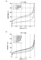
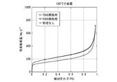
- FIG. 1 It is a figure which shows the manufacturing method of the filter molded object which concerns on embodiment of this invention, (a) is a top view, (b) is sectional drawing. Also, (1) is at the start, (2) is at the time of perforating the film resist, (3) is at the time of attaching the graphene and the film resist, (4) is from the time of adhesion by heating to the time of exposure, (5) Indicates the removal of the copper foil, and (6) indicates the opening of the graphene. It is a graph which shows the test result which measured the nitrogen adsorption amount of SWNH, (a) uses SWNH processed at 250 degreeC, (b) uses SWNH processed at 200 degreeC.
- graphene is used as a filter.
- graphene 1 grown on a copper foil 2 as a substrate is used for graphene.
- the graphene 1 is preferably single-layer graphene, but may be a multilayer.
- what has a Si substrate under the copper foil 2 may be sufficient, and in that case, it can remove and use a Si substrate with a reagent.
- the graphene may be held on an initial substrate for graphene made of a material other than the copper foil 2.
- the graphene 1 is a single crystal graphene having a large crystal size and is preferably a single layer. In this embodiment, single-layer graphene formed on a copper foil manufactured by Graphene Platform Co., Ltd. was used.
- a film resist 3 made of a photoresist was used as a support for holding the graphene 1 in the filter molded body.
- the performance required for the photoresist used here is strong enough to be used as a support, is a negative photoresist whose solubility in a developing solution is reduced by exposure, and polyimide or epoxy resin This is a resin having high heat resistance.
- Laytec is a film resist having a three-layer structure of a protective layer 4, a resist layer 5, and a support layer 6.
- the resist layer 5 is a layer made of a solder resist made of epoxy resin.
- the support layer 6 is formed on one surface of the resist layer 5 and protects the resist layer 5.
- the protective layer 4 is attached to the opposite surface of the resist layer 5 and serves to protect the resist layer 5 until it is attached to the graphene 1.
- the protective layer 4 and the support layer 6 can each be picked and removed from the resist layer 5 by hand. Since a thick film resist 3 is easier to use as a filter, it is preferable to use a film resist as thick as possible. In this embodiment, a Laytec (model number FZ-2730GA) having a film thickness of 30 ⁇ m is used.
- a water passage hole for allowing water to pass is previously formed.
- a biopsy trepan is used as a punch.
- a water passage hole is opened in the film resist 3 using a biopsy trepan having a diameter of 1 mm.
- the interval can be, for example, a lattice shape with an interval of 3 mm. This operation is performed in the yellow room in order to prevent the film resist 3 from being exposed.
- the film resist 3 is attached to the graphene 1.
- a vacuum laminator is used for pasting.
- a laminator for semiconductor processes such as MVLP-600 manufactured by Meiki Seisakusho Co., Ltd. is optimal, but a home laminator or a simple laminator may be used.
- the protective layer 4 of the film resist 3 is peeled off by hand and placed so that the resist layer 5 is in close contact with the layer of graphene 1 formed on the copper foil 2 and placed in a laminator film. Vacuum-press the second. This step is also performed in the yellow room in order to prevent the film resist 3 from being exposed.
- the graphene 1 and the film resist 3 are taken out from the laminator film, heated on a hot plate heated to 80 ° C. for 60 seconds, and then naturally cooled to room temperature.
- the resist layer 5 adheres to the graphene 1.
- it leaves still at 25 degreeC for 15 minutes.
- the film resist 3 resist layer 5
- the support layer of the film resist 3 is peeled off by hand to expose the resist layer 5.
- the film resist 3 is exposed to stabilize the resist layer 5 of the film resist 3 so that it is not dissolved in the solvent.
- i-line is irradiated by 180 mJ / cm 2 using a high-pressure mercury lamp.
- irradiation may be performed without setting a mask on the mask aligner, or irradiation may be performed with a quartz plate set as a dummy mask.
- the copper foil 2 on the graphene 1 is removed. Since the graphene 1 is destroyed when mechanically peeled off, the copper foil 2 is melted and removed by etching.
- the graphene 1 and the film resist 3 are floated on a Cu etching solution having a surface of the copper foil 2 facing down in a Cu etching solution of 0.5 mol / l hydrochloric acid / 0.5 mol / l iron (III) chloride mixed solution and 50 ° C. After leaving still for 1 hour, it is visually confirmed whether or not the copper foil 2 remains, and if etching is insufficient, etching is further performed for 10 minutes and the visual confirmation is repeated.
- the graphene 1 and the film resist 3 are floated on ultrapure water with the surface of the graphene 1 facing downward. Thereafter, the ultrapure water is replaced, and the same cleaning is performed twice to remove the etching solution. Next, the graphene 1 and the film resist 3 are rinsed with IPA, and put in a clean oven that has been preliminarily set at 160 ° C. and heated for 1 hour. By the heating process, the polymerization of the resist layer 5 proceeds and the film resist 3 is cured.
- the water passage hole needs to have a size that allows water to pass through but does not allow impurities or ions to pass through.
- the reason why the graphene 1 is perforated after removing the copper foil 2 is that if the copper foil 2 remains, it becomes a catalyst, and the graphene 1 is burned during heating.
- the perforation is performed by heating in air at 160 to 250 ° C. for a predetermined time.
- the term “in the air” is not limited to a mixed gas of about 20% O 2 and about 80% N 2 , and other contained gases are not limited as long as they contain 1% or more of O 2 .
- Mixed gases including noble gases and other gases are widely accepted.
- the reaction becomes abrupt and it is difficult to control the pores to a desired size, and the pore sizes are not uniform.
- the predetermined time is a time that brings about an effect of forming pores in graphene in a state where an atmosphere of 160 to 250 ° C. is maintained.
- the support may be any material that does not affect the low-temperature heat treatment of the graphene 1 and can support the graphene as a filter.
- a resin or other material having adhesiveness to the graphene 1 may be used as a support, or a resin or other support and a heat-resistant adhesive may be used in combination.
- the filter molded body thus produced can be used as a filter for a water purifier using a membrane filter, as shown in FIG.
- the filter molded body is cut into a 1/2 inch circle using a craft punch (made by Curl Office Equipment Co., Ltd.).
- the filter molded body is attached to the membrane filter holder 7 with the resist layer 5 facing upstream and the graphene 1 layer facing downstream, downstream of the 1/2 inch membrane filter.
- the membrane filter for example, “Isopore GTTP” (pore diameter 0.2 ⁇ m) manufactured by Merck Co., Ltd., which is a polycarbonate membrane filter, can be used.
- As the membrane filter holder 7, for example, “Swinex” manufactured by Merck & Co., Inc. can be used.
- the solution to be filtered (for example, seawater) is put into the syringe 8 and connected to the filter holder, and the syringe 8 is pushed to filter the solution. Water from which ions have been removed can be obtained.
- SWNH Single layer nanohorn
- adsorption amount of nitrogen at 77K was measured using an adsorption measuring device, Autosorb-iQ, manufactured by Cantachrome Instruments Japan GK.
- Nitrogen gas is supplied to the outside of SWNH, and the amount of nitrogen gas is measured after a predetermined time. When there is a hole through which nitrogen can pass on the peripheral surface of SWNH, nitrogen enters the inside of SWNH and is adsorbed on the inner wall. Therefore, the difference between the amount of supplied nitrogen and the amount of nitrogen outside SWNH after the test causes The amount of adsorption can be understood, and the size and size of the holes can be grasped.
- FIG. 2 (a) untreated SWNH, SWNH treated in air at 250 ° C. for 20 hours, and SWNH treated in air at 250 ° C. for 70 hours are prepared. Nitrogen was supplied at different temperatures and the amount of nitrogen adsorbed was measured. It can be seen that the SWNH treated for 20 hours has a large increase in the amount of nitrogen adsorbed from the low pressure to the high pressure compared to the SWNH that has not been treated, and thus a hole through which nitrogen passes is formed. Further, SWNH treated for 70 hours has an increased amount of adsorption compared with SWNH treated for 20 hours, which means that the number of SWNHs with holes is increased. That is, the amount of adsorption is increased by increasing the number of formed holes and consequently increasing the ratio of SWNH having holes. Therefore, it can be seen that the number of holes has increased.
- untreated SWNH and SWNH are treated in air at 200 ° C. for 20 hours, SWNH is treated in air at 200 ° C. for 70 hours, and SWNH is treated in air at 200 ° C.
- a sample treated for 100 hours and a sample treated with SWNH in air at 200 ° C. for 150 hours were prepared. Nitrogen was supplied at different relative pressures, and the nitrogen adsorption amount was measured. When SNWH is treated at 200 ° C., the carbon adsorption amount increases as the treatment time is increased, although not as much as when treated at 250 ° C. That is, it can be seen that the number of holes increased as the treatment time was increased.
- ion selectivity is measured for the graphene in which the holes are formed. Since the hydrated ionic radius of the cation is Li + > Na + > K + > Rb + > Cs + , the ion selectivity of the filter using graphene is measured according to the permeability of each ion. In the test, 24 mg of SWNH was added to 6 mL of a 20 ⁇ mol / L Li, Na, K, Rb, Cs mixed solution and allowed to stand at 30 ° C. for 24 hours, and then the ion concentration of the solution was measured by an ion chromatograph. If cations are attached to the inside of the SWNH through the holes opened in the SWNH, the measured ion concentration becomes small. 4 (a) and 4 (b) show the amount of ions that have passed through the pores measured from the concentration change.
- SWNH treated in air at 250 ° C for 20 hours SWNH treated in air at 250 ° C for 70 hours, and SWNH treated in air at 250 ° C for 100 hours are prepared. And put into the mixed solution. As a result, it can be seen that all cations are permeated regardless of the treatment time. Therefore, it was found that when the treatment was performed at 250 ° C. for 20 hours or more, the pores formed in the SWNH were enlarged and there was no ion selectivity.
- SWNH treated in air at 200 ° C. for 20 hours, SWNH treated in air at 200 ° C. for 50 hours, SWNH treated in air at 200 ° C. for 70 hours, SWNH Prepared in a 200 ° C. air for 100 hours and SWNH treated in a 200 ° C. air for 150 hours were prepared and placed in a mixed solution.
- SWNH treated for 20 hours hardly transmits ions with a large hydrated ion radius such as Li and Na, but transmits ions with a small hydrated ion radius such as K, Rb, and Cs. I understood.
- SWNH processed for 50 hours or more it turned out that a hole becomes large and all the ions permeate
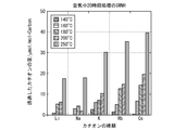
- FIG. 5 shows a comparison of ion selectivity for each heating temperature, with a treatment time of 20 hours.
- SWNH treated in air at 140 ° C. for 20 hours SWNH treated in air at 160 ° C. for 20 hours, SWNH treated in air at 180 ° C. for 20 hours, SWNH treated in air at 200 ° C.
- What processed for 20 hours and what processed SWNH for 20 hours in the air of 250 degreeC were prepared, and it put into the mixed solution.
- SWNH processed at 140 degreeC it turns out that a hole is hardly opened and ion has hardly permeate
- the permeation amounts of K, Rb, and Cs are small and do not have ion selectivity. It can be seen that SWNH treated at 200 ° C. has ion selectivity because it has a small amount of permeation of Li and Na and a large amount of permeation of K, Rb, and Cs. It can be seen that SWNH treated at 250 ° C. has a large permeation amount of all ions.
- the graphene 1 is set in the membrane filter holder 7 as described above, and 20 ⁇ mol / L of Li, Na, K, Rb, Cs mixed solution is allowed to permeate from the syringe 8, The ion concentration of the permeate was measured.
- the graphene prepared what was processed at 160 degreeC for 20 hours, what was processed at 200 degreeC for 20 hours, and what was processed at 250 degreeC for 20 hours was prepared.
- the graphene treated at 160 ° C. had small pores and hardly permeated each ion. It was found that the graphene treated at 200 ° C. hardly transmitted Li and Na but allowed K, Rb, and Cs to pass. Graphene treated at 250 ° C. was found to have large pores and allow all ions to pass through.
Landscapes
- Chemical & Material Sciences (AREA)
- Chemical Kinetics & Catalysis (AREA)
- Inorganic Chemistry (AREA)
- Organic Chemistry (AREA)
- Engineering & Computer Science (AREA)
- Physics & Mathematics (AREA)
- Manufacturing & Machinery (AREA)
- General Physics & Mathematics (AREA)
- Optics & Photonics (AREA)
- Materials Engineering (AREA)
- Nanotechnology (AREA)
- Architecture (AREA)
- Structural Engineering (AREA)
- Spectroscopy & Molecular Physics (AREA)
- Carbon And Carbon Compounds (AREA)
- Separation Using Semi-Permeable Membranes (AREA)
- Filtering Materials (AREA)
Abstract
Description
また、本発明は、フィルター成形体の製造方法に関し、特に、グラフェンを用いたフィルターを有するフィルター成形体の製造方法に関する。
転写工程においては、銅箔上に形成されたグラフェンの露出した面にPMMAをスピンコートして薄い保護膜を形成して乾燥させた後、銅箔を下にして50℃に熱したCuエッチング液に浮かべ、銅箔を除去する。
次いで、PMMAとグラフェンとの薄膜を超純水で洗浄し、表面を親水化したシリコン基板に乗せるようにして掬い上げる。
その後、樹脂等からなる所望の支持体で上記薄膜を掬い上げて乾燥させ、アセトン浸漬とIPA浸漬とを交互に数回繰り返してPMMAの保護膜を除去する。
最後に支持体およびグラフェンを乾燥させることによって、グラフェンを支持体に転写することができた。
また、グラフェンの層の表面にコーティングを形成したり除去したり、シリコン基板等で掬い上げたり離脱させたりする過程で、極めて薄いグラフェンを破損することがあった。
しかし、この方法ではグラフェンを支持しているフィルムレジストが熱で破損してしまうだけでなく、グラファイトの燃焼反応による穴あけのため、反応の制御が難しくグラフェンに開く通水孔の大きさも不均一であったため、均一な通水孔が必要になるフィルター成形体に用いるには不適当であった。
また、燃焼中に発生した樹脂等の支持体の燃えカスがグラフェンを汚染し、フィルター成形体の性能を低下させることがあった。
カーボンナノ素材に通水孔を形成する他の方法としては、酸素供給手段として硝酸塩をカーボンナノ素材に付着させ、300℃の真空または不活性ガス中で加熱して孔を形成するものがあった(特許文献6)。
また、所望の大きさの通水孔を有するグラフェンを用いたフィルター成形体を、容易な工程で製造することを課題とする。
第1の発明は、カーボンナノ素材に所望の大きさの孔を形成するカーボンナノ素材の穿孔方法であって、上記カーボンナノ素材を、160-250℃の酸素を含有する空気中で所定時間、低温加熱保持することを特徴とする。
また、実際にフィルターとして働くのは、グラフェンにおいて支持体の通水孔が形成された箇所であるところ、支持体に予め通水孔を穿設したことにより、この箇所ではグラフェンの層が支持体に触れることがないので、グラフェンが支持体の残滓によって汚損されるおそれがない。
このフィルター成形体には、フィルターとしてグラフェンを用いている。
図1(1)に示すように、グラフェンには、基板である銅箔2の上に成長させたグラフェン1を用いる。
グラフェン1としては単層グラフェンを用いるのが好ましいが、複層であってもよい。また、銅箔2の下にSi基板があるものであってもよく、その場合には試薬でSi基板を除去して用いることができる。さらに、グラフェンが銅箔2以外の材料からなるグラフェン用初期基板上に保持されているものでもよい。
グラフェン1は、単結晶のグラフェンで結晶サイズが大きいものであり、単層であることが望ましい。
この実施形態ではグラフェンプラットフォーム株式会社製の銅箔上に形成された単層グラフェンを用いた。
ここで用いるフォトレジストに必要な性能は、支持体として使うことができるくらい丈夫であること、露光によって現像液への溶解性が低下するネガ型のフォトレジストであること、および、ポリイミドやエポキシ樹脂のように高い耐熱性を有する樹脂であることである。
この実施形態では、エポキシ樹脂製のソルダーレジストとしてプリント基板の絶縁膜などに用いられる、日立化成株式会社製のフィルムレジスト「レイテック」を用いる。
レイテックは、保護層4、レジスト層5、支持層6の3層構造を有しているフィルムレジストである。レジスト層5はエポキシ樹脂製のソルダーレジストからなる層である。支持層6はレジスト層5の一面の上に形成され、レジスト層5を保護している。保護層4はレジスト層5の反対面に貼り付けられ、グラフェン1に貼り付けるまでの間、レジスト層5を保護する役割がある。保護層4および支持層6は、それぞれ手で摘んでレジスト層5から剥がすことができる。
フィルムレジスト3は厚いほうがフィルターとして使いやすいため、なるべく厚いフィルムレジストを使うことが好ましい。この実施形態では、膜厚30μmのレイテック(型番FZ-2730GA)を用いる。
孔開けには、穿孔器として生検トレパンを用いる。
例として、直径1mmの生検トレパンを使用してフィルムレジスト3に通水孔を開けていく。間隔は、例えば3mm間隔で格子状などにすることができる。
この作業は、フィルムレジスト3の感光を防止するためにイエロールームで行う。
フィルムレジスト3とグラフェン1との間の空気を抜いてしっかり圧着するため、貼り付けには、真空ラミネーターを用いる。例えば、株式会社名機製作所のMVLP-600などの半導体プロセス用のラミネーターが最適であるが、家庭用のラミネーターや簡易型のラミネーターを用いてもよい。
フィルムレジスト3の保護層4を手で剥がし、銅箔2上に形成されたグラフェン1の層にレジスト層5が密着するように載せて、ラミネーターフィルムの中に入れ、真空ラミネーターで-50kPaで20秒真空圧着する。
この工程も、フィルムレジスト3の感光を防止するためにイエロールームで行う。
その後、25℃で15分静置する。ここでフィルムレジスト3(レジスト層5)を落ち着かせることにより、後述する露光を均一に行うことができる。
次いで、フィルムレジスト3の支持層を手で剥がして、レジスト層5を露出させる。
これらの工程も、フィルムレジスト3の感光を防止するためにイエロールームで行う。
露光の工程では、高圧水銀灯を用いてi線を180mJ/cm2照射する。
例えば、マスクアライナーにマスクをセットしないで照射したり、石英板をダミーのマスクとしてセットして照射すればよい。
露光後には、25℃で30分ほど静置する。
機械的に剥がすとグラフェン1が破壊されてしまうため、エッチングで銅箔2を溶かして除去する。
0.5mol/l塩酸・0.5mol/l塩化鉄(III)混合水溶液、50℃のCuエッチング溶液に、銅箔2の面を下にして、グラフェン1およびフィルムレジスト3を浮かべる。1時間静置して、銅箔2が残っていないか目視で確認し、エッチングが不十分であればさらに10分エッチングして目視で確認することを繰り返す。
その後、超純水を入れ換えて同じ洗浄を2回行い、エッチング液を除去する。
次いで、グラフェン1およびフィルムレジスト3をIPAでリンスし、予め160℃にしておいたクリーンオーブンに入れて1時間加熱する。加熱の工程によって、レジスト層5の重合が進み、フィルムレジスト3が硬化する。
銅箔2を除去した後にグラフェン1の孔開けを行うのは、銅箔2が残っていると触媒となり、加熱時にグラフェン1を燃焼させてしまうからである。
本明細書において空気中とは、O2約20%、N2約80%の混合気体には限られず、O2を1%以上含むものであれば、その他の含有気体については限定されず、希ガスやその他の気体を含む混合気体が広く許容される。
しかし、160-250℃の低温ではフィルムレジスト3が破損せず、またグラフェン1に徐々にゆっくりと孔が開いて拡がっていくため、加熱時間の長短によって通水孔の大きさを制御することができる。また、200-250℃空気中で通水孔を開けると、燃えカスが発生しないためきれいな表面を保ったまま通水孔を開けることができる。
160℃未満では長時間加熱をしても、グラフェンにほとんど孔を形成することできない。また、250℃以上では反応が急激になり孔を所望の大きさにコントロールすることが難しく、また孔の大きさが不均一になってしまう。
また、低温加熱の温度は、特に200-250℃に設定するのが望ましい。
たとえば、200℃の空気中に20時間置いて通水孔を形成すると、このように製造したフィルター成形体は、海水から塩分を除去して真水にすることができる。
たとえば、クラフトパンチ(カール事務器株式会社製など)を使ってフィルター成形体を1/2インチの円形に切り取る。このフィルター成形体のレジスト層5を上流に向け、グラフェン1の層を下流に向けて、1/2インチのメンブレンフィルターの下流に取り付け、メンブレンフィルターホルダー7にセットする。
メンブレンフィルターとしては、例えばポリカーボネート製メンブレンフィルターであるメルク株式会社製の「アイソポアGTTP」(孔径0.2μm)を使用することができる。
メンブレンフィルターホルダー7としては、例えばメルク株式会社製の「スウィネックス」を用いることができる。
このような浄水装置を用いて溶液の濾過を行うには、シリンジ8に濾過する溶液(例えば海水など)を入れて、フィルターホルダーに接続し、シリンジ8を押して溶液を濾過することにより、不純物やイオンを除去した水を得ることができる。
本発明の効果を測定するために試験を行った。
測定試験のため、単層ナノホーン(SWNH)を用いる。SWNHは、基本的な構造はグラフェンと同じであるが、円錐形状に形成されている。
この試験では、カンタクローム・インスツルメンツ・ジャパン合同会社の吸着測定装置、Autosorb-iQ を用いて、77Kでの窒素の吸着量を測定した。SWNHの外側に窒素ガスを供給し、所定時間後に窒素ガスの量を測定する。SWNHの周面に窒素が通過できる孔が存在する場合には、窒素がSWNHの内部に入り込み内壁に吸着するため、供給した窒素の量と試験後のSWNH外部の窒素の量との差によって窒素吸着量がわかり、孔の径および数の大小が把握できる。
20時間処理したSWNHは、処理をしていないSWNHに比べて、低圧下から高圧下にかけて窒素吸着量が大きく増えており、窒素が通過する孔が形成されたことがわかる。
また、70時間処理したSWNHは、20時間処理したSWNHに比べて吸着量が増えており、これは、孔が開いたSWNHの数が増えたことを意味する。つまり、形成された孔の数が増え結果的に孔の開いたSWNHの割合が増えることで吸着量が大きくなったためである。したがって、孔の数が増えたことがわかる。
SNWHを200℃で処理すると、250℃で処理したときほどではないが、処理時間を長くするにつれて炭素吸着量が大きくなっている。すなわち、処理時間を長くするほど孔の数が増えたことがわかる。
50時間処理したSNWHは、処理していないSNWHに比べて、低圧下から高圧下にかけて窒素吸着量が増えており、窒素が通過する孔が形成されたことがわかる。
他方、70時間処理したSNWHは、50時間処理したSNWHに比べて窒素吸着量がほぼ増えていない。そのため、180℃では処理時間を増やしても孔の数がほとんど増大しないことがわかった。
カチオンの水和イオン半径は、Li+>Na+>K+>Rb+>Cs+であるため、それぞれのイオンの透過度によってグラフェンを用いたフィルターのイオン選択性を測定する。
試験は、20μmol/LのLi,Na,K,Rb,Cs混合溶液6mLに24mgのSWNHを入れて、30℃で24時間静置した後、溶液のイオン濃度をイオンクロマトグラフで測定した。カチオンがSWNHに開いた孔を通ってSWNHの内部に付着すれば、測定されるイオン濃度は小さくなる。図4(a)(b)は、その濃度変化から、孔を透過したイオンの量を測定したものである。
この結果、処理時間の長短に関係なく、全てのカチオンが透過していることがわかる。そのため、250℃で20時間以上処理すると、SWNHに形成される孔が大きくなりイオン選択性を有しないことがわかった。
この結果、20時間処理したSWNHでは、LiやNaのように水和イオン半径が大きいイオンはほとんど透過せず、K,Rb,Csのように水和イオン半径が小さいイオンが透過していることがわかった。
他方、50時間以上処理したSWNHでは、孔が大きくなり全てのイオンが透過していることがわかった。
SWNHを140℃の空気中で20時間処理したもの、SWNHを160℃の空気中で20時間処理したもの、SWNHを180℃の空気中で20時間処理したもの、SWNHを200℃の空気中で20時間処理したもの、SWNHを250℃の空気中で20時間処理したものを用意し、混合溶液に入れた。
140℃で処理したSWNHでは、孔がほとんど開かず、イオンがほとんど透過していないことがわかる。
160℃で処理したSWNHおよび180℃で処理したSWNHでは、孔が小さく少量のイオンしか通過していないことがわかる。また、K,Rb,Csの透過量も小さく、イオン選択性を有しないことがわかる。
200℃で処理したSWNHは、Li,Naの透過量が小さく、K,Rb,Csの透過量が大きいため、イオン選択性を有することがわかる。
250℃で処理したSWNHは、全てのイオンの透過量が大きくなっていることがわかる。
グラフェンは、160℃で20時間処理したもの、200℃で20時間処理したもの、250℃で20時間処理したものを用意した。
200℃で処理したグラフェンは、Li,Naをほとんど透過させず、K,Rb,Csを透過させることがわかった。
250℃で処理したグラフェンは孔が大きく、全てのイオンを透過させることがわかった。
2 銅箔
3 フィルムレジスト
4 保護層
5 レジスト層
6 支持層
7 メンブレンフィルターホルダー
8 シリンジ
Claims (4)
- カーボンナノ素材に所望の大きさの孔を形成するカーボンナノ素材の穿孔方法であって、
上記カーボンナノ素材を、160-250℃の酸素を含有する空気中で所定時間、低温加熱保持することを特徴とするカーボンナノ素材の穿孔方法。 - 濾過材としてグラフェンの層を有するフィルター成形体の製造方法であって、
グラフェン用初期基板上に形成されたグラフェンの層に、予め通水孔を穿設された支持体の層を貼り付ける工程と、
上記グラフェンの層を160-250℃の酸素を含有する空気中で所定時間、低温加熱保持し通水孔を形成する工程とを有することを特徴とするフィルター成形体の製造方法。 - 上記支持体がフィルムレジストであり、
上記フィルムレジストを露光させ安定させる工程を含むことを特徴とする請求項2記載のフィルター成形体の製造方法。 - 上記グラフェンの層を低温加熱保持し通水孔を形成する工程が、200-250℃の酸素を含有する空気中で行われることを特徴とする請求項2記載のフィルター成形体の製造方法。
Priority Applications (8)
| Application Number | Priority Date | Filing Date | Title |
|---|---|---|---|
| JP2016531251A JP6588907B2 (ja) | 2014-06-30 | 2015-06-17 | カーボンナノ素材の穿孔方法およびフィルター成形体の製造方法 |
| AU2015285551A AU2015285551A1 (en) | 2014-06-30 | 2015-06-17 | Method for perforating carbon nanomaterial, and method for producing filter molded article |
| EP15814634.0A EP3165277A4 (en) | 2014-06-30 | 2015-06-17 | Method for perforating carbon nanomaterial, and method for producing filter molded article |
| CN201580027835.9A CN106457162A (zh) | 2014-06-30 | 2015-06-17 | 碳纳米材料的穿孔方法以及过滤器成形体的制造方法 |
| US15/322,682 US20170128890A1 (en) | 2014-06-30 | 2015-06-17 | Method for perforating carbon nanomaterial and method for producing filter molded article |
| SA516380527A SA516380527B1 (ar) | 2014-06-30 | 2016-12-19 | طريقة للحصول منتج مقولب كمرشح |
| AU2019204970A AU2019204970B2 (en) | 2014-06-30 | 2019-07-11 | Method for perforating carbon nanomaterial, and method for producing filter molded article |
| US16/697,967 US20200101424A1 (en) | 2014-06-30 | 2019-11-27 | Method for perforating carbon nanomaterial, and method for producing filter molded article |
Applications Claiming Priority (2)
| Application Number | Priority Date | Filing Date | Title |
|---|---|---|---|
| JP2014-134449 | 2014-06-30 | ||
| JP2014134449 | 2014-06-30 |
Related Child Applications (2)
| Application Number | Title | Priority Date | Filing Date |
|---|---|---|---|
| US15/322,682 A-371-Of-International US20170128890A1 (en) | 2014-06-30 | 2015-06-17 | Method for perforating carbon nanomaterial and method for producing filter molded article |
| US16/697,967 Division US20200101424A1 (en) | 2014-06-30 | 2019-11-27 | Method for perforating carbon nanomaterial, and method for producing filter molded article |
Publications (1)
| Publication Number | Publication Date |
|---|---|
| WO2016002509A1 true WO2016002509A1 (ja) | 2016-01-07 |
Family
ID=55019056
Family Applications (1)
| Application Number | Title | Priority Date | Filing Date |
|---|---|---|---|
| PCT/JP2015/067400 Ceased WO2016002509A1 (ja) | 2014-06-30 | 2015-06-17 | カーボンナノ素材の穿孔方法およびフィルター成形体の製造方法 |
Country Status (8)
| Country | Link |
|---|---|
| US (2) | US20170128890A1 (ja) |
| EP (2) | EP3263210A1 (ja) |
| JP (1) | JP6588907B2 (ja) |
| CN (2) | CN109908768B (ja) |
| AU (2) | AU2015285551A1 (ja) |
| SA (1) | SA516380527B1 (ja) |
| TW (2) | TW201609532A (ja) |
| WO (1) | WO2016002509A1 (ja) |
Cited By (3)
| Publication number | Priority date | Publication date | Assignee | Title |
|---|---|---|---|---|
| JPWO2016024506A1 (ja) * | 2014-08-11 | 2017-06-22 | 国立大学法人信州大学 | フィルター成形体の製造方法 |
| WO2019087624A1 (ja) | 2017-10-30 | 2019-05-09 | 国立大学法人信州大学 | フィルター成形体の製造方法 |
| CN110869109A (zh) * | 2017-07-14 | 2020-03-06 | 国立大学法人信州大学 | 石墨烯的纳米窗口结构和高纯度气体的制造方法 |
Families Citing this family (1)
| Publication number | Priority date | Publication date | Assignee | Title |
|---|---|---|---|---|
| CN108176247A (zh) * | 2018-02-28 | 2018-06-19 | 长沙理工大学 | 用于盐水分离的纳米复合过滤膜及其制备方法和应用 |
Citations (3)
| Publication number | Priority date | Publication date | Assignee | Title |
|---|---|---|---|---|
| JP2002097008A (ja) * | 2000-09-20 | 2002-04-02 | Japan Science & Technology Corp | 単層カーボンナノチューブの開孔方法 |
| WO2008090728A1 (ja) * | 2007-01-25 | 2008-07-31 | Nec Corporation | 触媒担持カーボンナノホーン複合体およびその製造方法 |
| JP2009073727A (ja) * | 2007-08-29 | 2009-04-09 | Olympus Corp | カーボンナノチューブ加工方法及びそれによって加工されたカーボンナノチューブ |
Family Cites Families (15)
| Publication number | Priority date | Publication date | Assignee | Title |
|---|---|---|---|---|
| WO2003099717A1 (en) | 2002-05-27 | 2003-12-04 | Japan Science And Technology Agency | High-density carbon nanohorns and process for producing the same |
| US20040060867A1 (en) * | 2002-09-27 | 2004-04-01 | Bmc Industries, Inc. | Membrane support devices and methods of manufacturing |
| US8409450B2 (en) * | 2008-03-24 | 2013-04-02 | The Regents Of The University Of California | Graphene-based structure, method of suspending graphene membrane, and method of depositing material onto graphene membrane |
| US7993524B2 (en) | 2008-06-30 | 2011-08-09 | Nanoasis Technologies, Inc. | Membranes with embedded nanotubes for selective permeability |
| WO2010074918A1 (en) * | 2008-12-23 | 2010-07-01 | The Trustees Of The University Of Pennsylvania | High yield preparation of macroscopic graphene oxide membranes |
| ES2717903T3 (es) * | 2009-10-16 | 2019-06-26 | Graphene Square Inc | Procedimiento de transferencia de rollo a rollo de grafeno, rollo de grafeno producido por el procedimiento, y equipo de transferencia de rollo a rollo para grafeno |
| WO2011094204A2 (en) * | 2010-01-26 | 2011-08-04 | Wisconsin Alumni Research Foundation | Methods of fabricating large-area, semiconducting nanoperforated graphene materials |
| US8361321B2 (en) * | 2010-08-25 | 2013-01-29 | Lockheed Martin Corporation | Perforated graphene deionization or desalination |
| JP5926035B2 (ja) | 2011-11-21 | 2016-05-25 | Jx金属株式会社 | グラフェン製造用銅箔及びグラフェン製造用銅箔の製造方法、並びにグラフェンの製造方法 |
| CN102557004B (zh) * | 2011-12-23 | 2015-01-28 | 上海交通大学 | 一种通过磁场控制碳纳米材料生长形貌的方法 |
| JP2013144621A (ja) | 2012-01-16 | 2013-07-25 | Panasonic Corp | グラフェン膜、グラフェン膜の製造方法、グラフェンデバイス、およびグラフェンデバイスの製造方法 |
| WO2013112164A1 (en) * | 2012-01-26 | 2013-08-01 | Empire Technology Development, Llc | Graphene membrane with regular angstrom-scale pores |
| SG11201405346RA (en) * | 2012-03-21 | 2014-10-30 | Lockheed Corp | Methods for perforating graphene using an activated gas stream and perforated graphene produced therefrom |
| US9463421B2 (en) * | 2012-03-29 | 2016-10-11 | Lockheed Martin Corporation | Planar filtration and selective isolation and recovery device |
| CN103145115B (zh) * | 2013-02-01 | 2014-11-19 | 中科院广州化学有限公司 | 表面羧基官能化的碳纳米材料及其制备方法和应用 |
-
2015
- 2015-06-17 EP EP17184153.9A patent/EP3263210A1/en not_active Withdrawn
- 2015-06-17 CN CN201910268723.2A patent/CN109908768B/zh not_active Expired - Fee Related
- 2015-06-17 CN CN201580027835.9A patent/CN106457162A/zh active Pending
- 2015-06-17 US US15/322,682 patent/US20170128890A1/en not_active Abandoned
- 2015-06-17 EP EP15814634.0A patent/EP3165277A4/en not_active Withdrawn
- 2015-06-17 JP JP2016531251A patent/JP6588907B2/ja active Active
- 2015-06-17 AU AU2015285551A patent/AU2015285551A1/en not_active Abandoned
- 2015-06-17 WO PCT/JP2015/067400 patent/WO2016002509A1/ja not_active Ceased
- 2015-06-30 TW TW104121074A patent/TW201609532A/zh unknown
- 2015-06-30 TW TW107131136A patent/TWI664143B/zh not_active IP Right Cessation
-
2016
- 2016-12-19 SA SA516380527A patent/SA516380527B1/ar unknown
-
2019
- 2019-07-11 AU AU2019204970A patent/AU2019204970B2/en not_active Ceased
- 2019-11-27 US US16/697,967 patent/US20200101424A1/en not_active Abandoned
Patent Citations (3)
| Publication number | Priority date | Publication date | Assignee | Title |
|---|---|---|---|---|
| JP2002097008A (ja) * | 2000-09-20 | 2002-04-02 | Japan Science & Technology Corp | 単層カーボンナノチューブの開孔方法 |
| WO2008090728A1 (ja) * | 2007-01-25 | 2008-07-31 | Nec Corporation | 触媒担持カーボンナノホーン複合体およびその製造方法 |
| JP2009073727A (ja) * | 2007-08-29 | 2009-04-09 | Olympus Corp | カーボンナノチューブ加工方法及びそれによって加工されたカーボンナノチューブ |
Non-Patent Citations (1)
| Title |
|---|
| LIU,LI ET AL.: "Graphene Oxidation: Thickness- Dependent Etching and Strong Chemical Doping", NANO LETT., vol. 8, no. 7, 2008, pages 1965 - 1970, XP055066530 * |
Cited By (5)
| Publication number | Priority date | Publication date | Assignee | Title |
|---|---|---|---|---|
| JPWO2016024506A1 (ja) * | 2014-08-11 | 2017-06-22 | 国立大学法人信州大学 | フィルター成形体の製造方法 |
| JP2019162635A (ja) * | 2014-08-11 | 2019-09-26 | 国立大学法人信州大学 | フィルター成形体の製造方法 |
| CN110869109A (zh) * | 2017-07-14 | 2020-03-06 | 国立大学法人信州大学 | 石墨烯的纳米窗口结构和高纯度气体的制造方法 |
| US11278849B2 (en) | 2017-07-14 | 2022-03-22 | Shinshu University | Graphene nanowindow structure and method for producing highly pure gas |
| WO2019087624A1 (ja) | 2017-10-30 | 2019-05-09 | 国立大学法人信州大学 | フィルター成形体の製造方法 |
Also Published As
| Publication number | Publication date |
|---|---|
| TW201900555A (zh) | 2019-01-01 |
| TW201609532A (zh) | 2016-03-16 |
| EP3263210A1 (en) | 2018-01-03 |
| CN109908768A (zh) | 2019-06-21 |
| US20170128890A1 (en) | 2017-05-11 |
| EP3165277A4 (en) | 2018-03-14 |
| AU2019204970B2 (en) | 2020-09-10 |
| US20200101424A1 (en) | 2020-04-02 |
| EP3165277A1 (en) | 2017-05-10 |
| AU2015285551A1 (en) | 2017-01-12 |
| AU2019204970A1 (en) | 2019-08-01 |
| CN106457162A (zh) | 2017-02-22 |
| JPWO2016002509A1 (ja) | 2017-06-22 |
| JP6588907B2 (ja) | 2019-10-09 |
| CN109908768B (zh) | 2021-11-19 |
| TWI664143B (zh) | 2019-07-01 |
| SA516380527B1 (ar) | 2022-04-28 |
Similar Documents
| Publication | Publication Date | Title |
|---|---|---|
| US20200101424A1 (en) | Method for perforating carbon nanomaterial, and method for producing filter molded article | |
| JP6715470B2 (ja) | フィルター成形体の製造方法 | |
| JP6588923B2 (ja) | フィルター成形体の製造方法 | |
| JP7093932B2 (ja) | フィルター成形体の製造方法 |
Legal Events
| Date | Code | Title | Description |
|---|---|---|---|
| 121 | Ep: the epo has been informed by wipo that ep was designated in this application |
Ref document number: 15814634 Country of ref document: EP Kind code of ref document: A1 |
|
| DPE1 | Request for preliminary examination filed after expiration of 19th month from priority date (pct application filed from 20040101) | ||
| REEP | Request for entry into the european phase |
Ref document number: 2015814634 Country of ref document: EP |
|
| WWE | Wipo information: entry into national phase |
Ref document number: 2015814634 Country of ref document: EP |
|
| ENP | Entry into the national phase |
Ref document number: 2016531251 Country of ref document: JP Kind code of ref document: A |
|
| WWE | Wipo information: entry into national phase |
Ref document number: 15322682 Country of ref document: US |
|
| NENP | Non-entry into the national phase |
Ref country code: DE |
|
| ENP | Entry into the national phase |
Ref document number: 2015285551 Country of ref document: AU Date of ref document: 20150617 Kind code of ref document: A |
|
| WWE | Wipo information: entry into national phase |
Ref document number: 516380527 Country of ref document: SA |