WO2016002205A1 - 携帯端末充電装置 - Google Patents
携帯端末充電装置 Download PDFInfo
- Publication number
- WO2016002205A1 WO2016002205A1 PCT/JP2015/003280 JP2015003280W WO2016002205A1 WO 2016002205 A1 WO2016002205 A1 WO 2016002205A1 JP 2015003280 W JP2015003280 W JP 2015003280W WO 2016002205 A1 WO2016002205 A1 WO 2016002205A1
- Authority
- WO
- WIPO (PCT)
- Prior art keywords
- charging
- coils
- detection
- coil
- detection coils
- Prior art date
- Legal status (The legal status is an assumption and is not a legal conclusion. Google has not performed a legal analysis and makes no representation as to the accuracy of the status listed.)
- Ceased
Links
Images






Classifications
-
- H—ELECTRICITY
- H01—ELECTRIC ELEMENTS
- H01F—MAGNETS; INDUCTANCES; TRANSFORMERS; SELECTION OF MATERIALS FOR THEIR MAGNETIC PROPERTIES
- H01F38/00—Adaptations of transformers or inductances for specific applications or functions
- H01F38/14—Inductive couplings
-
- H—ELECTRICITY
- H02—GENERATION; CONVERSION OR DISTRIBUTION OF ELECTRIC POWER
- H02J—ELECTRIC POWER NETWORKS; CIRCUIT ARRANGEMENTS OR SYSTEMS FOR SUPPLYING OR DISTRIBUTING ELECTRIC POWER; SYSTEMS FOR STORING ELECTRIC ENERGY
- H02J50/00—Circuit arrangements or systems for wireless supply or distribution of electric power
- H02J50/10—Circuit arrangements or systems for wireless supply or distribution of electric power using inductive coupling
-
- H—ELECTRICITY
- H02—GENERATION; CONVERSION OR DISTRIBUTION OF ELECTRIC POWER
- H02J—ELECTRIC POWER NETWORKS; CIRCUIT ARRANGEMENTS OR SYSTEMS FOR SUPPLYING OR DISTRIBUTING ELECTRIC POWER; SYSTEMS FOR STORING ELECTRIC ENERGY
- H02J50/00—Circuit arrangements or systems for wireless supply or distribution of electric power
- H02J50/10—Circuit arrangements or systems for wireless supply or distribution of electric power using inductive coupling
- H02J50/12—Circuit arrangements or systems for wireless supply or distribution of electric power using inductive coupling of the resonant type
-
- H—ELECTRICITY
- H02—GENERATION; CONVERSION OR DISTRIBUTION OF ELECTRIC POWER
- H02J—ELECTRIC POWER NETWORKS; CIRCUIT ARRANGEMENTS OR SYSTEMS FOR SUPPLYING OR DISTRIBUTING ELECTRIC POWER; SYSTEMS FOR STORING ELECTRIC ENERGY
- H02J50/00—Circuit arrangements or systems for wireless supply or distribution of electric power
- H02J50/90—Circuit arrangements or systems for wireless supply or distribution of electric power involving detection or optimisation of position, e.g. alignment
-
- H—ELECTRICITY
- H02—GENERATION; CONVERSION OR DISTRIBUTION OF ELECTRIC POWER
- H02J—ELECTRIC POWER NETWORKS; CIRCUIT ARRANGEMENTS OR SYSTEMS FOR SUPPLYING OR DISTRIBUTING ELECTRIC POWER; SYSTEMS FOR STORING ELECTRIC ENERGY
- H02J7/00—Circuit arrangements for charging or discharging batteries or for supplying loads from batteries
- H02J7/70—Circuit arrangements for charging or discharging batteries or for supplying loads from batteries characterised by the mechanical construction
- H02J7/731—Circuit arrangements for charging or discharging batteries or for supplying loads from batteries characterised by the mechanical construction specially adapted for holding portable devices containing batteries
-
- H—ELECTRICITY
- H04—ELECTRIC COMMUNICATION TECHNIQUE
- H04M—TELEPHONIC COMMUNICATION
- H04M19/00—Current supply arrangements for telephone systems
Definitions
- the present invention relates to a mobile terminal charging device for charging a mobile terminal such as a mobile phone, and an automobile equipped with the same.
- Mobile terminals such as mobile phones have extremely high functions, and the power consumption increases accordingly.
- such a charging device includes a support plate whose front side is a portable terminal installation portion, and a charging coil disposed on the back side of the support plate so as to face the support plate.
- the portable terminal When the portable terminal is placed on the portable terminal installation portion, the portable terminal can be charged with the magnetic flux from the charging coil (for example, the similar one is described in Patent Document 1 below). Exist).
- the present invention provides a mobile terminal charging device that reduces power loss and further suppresses adverse effects on other devices using electromagnetic waves.
- the portable terminal charging device includes a plurality of charging coils, a plurality of detection coils, and a control unit electrically connected to the charging coils and the detection coils.
- the control unit drives the plurality of detection coils, and monitors impedance changes detected by the plurality of detection coils during driving.
- the charging coil corresponding to the detection coil which detected the impedance change is selected among several charging coils, and a magnetic field is output from the selected charging coil.
- a response signal negotiated with the portable terminal is received in response to the magnetic field, the portable terminal is charged using the selected charging coil.
- one embodiment of the present invention is an automobile equipped with the above mobile terminal charging device.
- the mobile terminal charging device of the present invention since the ping operation when detecting the position of the mobile terminal can be reduced, the power loss is small and the influence on other devices using electromagnetic waves is suppressed. Can do.
- FIG. 1 The perspective view which shows the state which installed the portable terminal charging device by Embodiment 1 of this invention in the vehicle interior of a motor vehicle.
- the perspective view of the portable terminal charging device shown in FIG. The perspective view which shows the state by which the portable terminal was set
- the perspective side view of the portable terminal charging device shown in FIG. The figure which shows a part of portable terminal charging device shown in FIG.
- the charging device described in Patent Document 1 employs a multi-coil system. In the multi-coil system, only a part of the coils corresponding to the position where the mobile terminal is placed is used for charging among the plurality of charging coils.
- Patent Document 1 in order to detect that a secondary device (charging object) is placed on a charging device and its position, a magnetic field output (ping) in a short time in turn in each charging coil. Ping).
- the secondary device information is transmitted from the secondary device to the charging device in response to the ping.
- the charging device receives it, communication is established, and charging is started in earnest.
- a coil having a high received intensity of information transmitted from the secondary device is selected from among the plurality of charging coils of the charging apparatus, and charging is performed using the selected coil. For this reason, only the charging coil corresponding to the position where the secondary device is placed is used for full-scale charging.
- each charging coil repeats ping whenever the secondary device is not installed in the charging device. For this reason, a magnetic field is generated in the air, and power loss is large.
- the magnetic field repeatedly generated by ping may adversely affect other in-vehicle devices that use electromagnetic waves. For example, it interferes with the frequency band of the in-vehicle radio and degrades sound.
- FIG. 1 is a perspective view showing a state in which the portable terminal charging device 5 according to the first embodiment of the present invention is installed in the passenger compartment 2 of the automobile
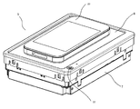
- FIG. 2 is a perspective view of the portable terminal charging device 5
- FIG. It is a perspective view which shows the state in which the portable terminal 23 was set
- FIG. 1 is a perspective view showing a state in which the portable terminal charging device 5 according to the first embodiment of the present invention is installed in the passenger compartment 2 of the automobile
- FIG. 2 is a perspective view of the portable terminal charging device 5
- FIG. It is a perspective view which shows the state in which the portable terminal 23 was set
- a handle 3 is installed in the front of the passenger compartment 2 of the automobile 1.
- an electronic device 4 that displays music, video playback, car navigation video, and the like is installed.
- a portable terminal charging device 5 is installed behind the electronic device 4 in the passenger compartment 2.
- the portable terminal charging device 5 has a box-shaped main body case 7 with a support plate 6 disposed on the top thereof.
- the portable terminal 23 can be charged wirelessly by installing the portable terminal 23 on the upper surface of the support plate 6 (portable terminal installation portion).
- FIG. 4 is a side view of the main body case 7 seen through.
- a charging coil substrate 8 on which a plurality of charging coils are formed and a detection coil substrate 9 on which a plurality of detection coils are formed are mounted inside the main body case 7. Furthermore, the control part 10 electrically connected with the charging coil and the detection coil is mounted.
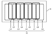
- FIGS. 5 and 6 are views showing a charging coil substrate 8 and a detection coil substrate 9 which are part of the mobile terminal charging device 5, respectively.
- the charging coil substrate 8 has a plurality of charging coils 11 formed thereon.
- the charging coil substrate 8 has a plurality of charging coils 11 formed thereon.
- five charging coils Lc1 to Lc5 are provided.
- Each charging coil is formed by winding a metal wire on a spiral.
- a plurality of detection coils 12 are formed on the detection coil substrate 9.
- the plurality of detection coils 12 are detected by a first set of five detection coils L1, L3, L5, L7, and L9 formed on the lower surface of the detection coil substrate 9 (the surface facing the bottom plate of the main body case 7).
- a second set of four detection coils L2, L4, L6, and L8 formed on the upper surface (the surface facing the support plate 6) of the coil substrate 9 is included.
- the plurality of detection coils 12 are overlapped in plan view so that the end in the arrangement direction of the first set of detection coils and the center in the arrangement direction of the second set of detection coils are located on the same line. Has been placed.
- the first set of detection coils is shown shifted from the second set of detection coils in the lower direction of the drawing for easy understanding. Actually, it is preferable that the midpoints of the long sides of the first set of detection coils and the midpoints of the long sides of the second set of detection coils are arranged on the same line in plan view.
- FIG. 7 is a control block diagram of the mobile terminal charging device 5 and shows details of the control unit 10.
- the control unit 10 includes a detection coil driving unit 13 and a charging coil driving unit 14.
- the detection coil drive unit 13 includes a self-excited oscillation circuit 15, a detection coil selection circuit 16, and an impedance measurement circuit 17.
- the impedance measurement circuit 17 monitors changes in impedance of each of the plurality of detection coils 12.
- the detection coil selection circuit 16 selectively connects each of the plurality of detection coils 12 to the self-excited oscillation circuit 15 and the impedance measurement circuit 17.
- the charging coil driving unit 14 includes a charging circuit 18 and a charging coil selection circuit 19.
- the charging coil selection circuit 19 selectively connects each of the plurality of charging coils 11 and the charging circuit 18.
- the charging circuit 18 converts the DC power from the in-vehicle power source (battery) into AC power having an appropriate amplitude and frequency and supplies the AC power to the charging coil 11.
- the charging circuit 18 includes a DC-DC converter 20 and a full bridge inverter 21.
- a memory (not shown) built in the control unit 10 stores a threshold value for determining an impedance change of the detection coil 12 described later.
- the control unit 10 detects whether or not the mobile terminal 23 is placed on the upper surface (mobile terminal installation unit) of the support plate 6 and also the mobile terminal 23. Is detected (more precisely, the position of the receiving coil inside the portable terminal). Specifically, the self-excited oscillation circuit 15 is turned on, and pulse waves are output to the plurality of detection coils 12 (S1). At this time, the impedance measurement circuit 17 measures the impedance of each of the plurality of detection coils 12 in order (S2). Then, it is monitored which of the plurality of detection coils 12 has the impedance change (S3).
- the output voltage of the magnetic field transmitted from the detection coil is extremely small compared to the magnetic field output in the ping operation described later, and therefore, the influence on other in-vehicle devices using electromagnetic waves is small.
- the oscillation voltage of the detection coil is 3.3V
- the output voltage of the ping operation is 10V or more.
- the control unit 10 determines that the object is a portable terminal that can be charged, and starts a charging operation.
- the control unit 10 determines that the object is not a mobile terminal but a metal foreign object such as a coin, and does not enter the charging operation.
- the impedance measurement circuit 17 measures each resonance frequency and / or resonance voltage of the detection coil 12 and compares it with a threshold value stored in the memory.
- the threshold is set to a resonance frequency or resonance voltage value at a normal level when the portable terminal 23 is not placed. It can be seen that the impedance has changed due to the change in the resonance frequency and / or the resonance voltage in any one of the plurality of detection coils 12. More specifically, a change in resonance voltage reflects a resistance component (R component) of impedance change, and a resonance frequency reflects a reactance component (L component) of impedance change. When a metal object is placed on the upper surface of the support plate 6, the resonance frequency increases and the resonance voltage decreases.
- the process proceeds to S4. If no change in impedance is detected, the process returns to S2 again, and the impedance measurement of the detection coil 12 is performed again.
- the control unit 10 confirms whether or not the object placed on the upper surface of the support plate 6 is a portable terminal that can be charged. Specifically, a charging coil corresponding to a detection coil that has detected an impedance change is selected from the plurality of charging coils 11 (S4), and a magnetic field is output from the selected charging coil (S6). Note that the self-excited oscillation circuit 15 is temporarily turned off before the magnetic field output from the charging coil (S5).
- the control unit 10 confirms whether a response signal negotiated in advance with the mobile terminal is obtained (S7).
- a predetermined response signal is obtained in S7, it is determined that communication with the portable terminal 23 has been established, and a full-scale charging operation is started (S8).
- S7 when a predetermined response signal is not obtained, it is determined that communication is not established, and the process returns to S1 again.
- an operation for outputting a magnetic field for a short time until the presence / absence of a response from the portable terminal 23 is determined is referred to as a ping operation.
- the mobile terminal 23 returns a predetermined response signal to the mobile terminal charging device 5 in response to receiving the magnetic field output from the charging coil of the mobile terminal charging device 5. At this time, the portable terminal 23 varies the value of the load connected to the power receiving coil.
- the response signal is received by detecting the reflected impedance of the load fluctuation by the signal receiving circuit connected to the charging coil of the mobile terminal charging device 5. Such a signal transmission / reception method is called load modulation.
- the response signal returned from the portable terminal 23 may be a simple signal that only indicates that communication has been established, or may include ID information that indicates the type or the like of the portable terminal 23.
- the control unit 10 monitors whether the communication with the portable terminal 23 is continuously established, and continues the charging if the communication is continued. If the communication is interrupted, the process returns to S1 to confirm again the presence or absence of the mobile terminal. Further, during the charging operation (S8), the control unit 10 monitors whether or not a signal indicating that the charging is completed is transmitted from the portable terminal 23. If the charging is not completed, the control unit 10 continues the charging. If is completed, charging is stopped (S9).
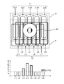
- FIG. 9 shows an example of an arrangement relationship between the charging coil 11 and the detection coil 12 in the portable terminal charging device 5 and an impedance change detected by each detection coil when the power receiving coil 24 is placed on the detection coil 12. It is a figure explaining.
- the detection coil substrate 9 is shown shifted from the charging coil substrate 8 in the lower direction of the drawing for easy understanding.
- the detection coils L1, L3, L5, L7, and L9 are shown as being shifted downward in the drawing with respect to the detection coils L2, L4, L6, and L8.
- the midpoint of the long side of the charging coil and the midpoint of the long side of the detection coil are arranged on the same line in plan view.
- the detection coil 12 includes a detection coil 12 that is disposed almost immediately above the charging coil 11 and a detection coil 12 that is disposed across two adjacent charging coils.
- the center in the arrangement direction of each detection coil and the center in the arrangement direction of each charging coil are located on substantially the same line. Therefore, each of the detection coils L1, L3, L5, L7, and L9 is disposed almost directly above the corresponding charging coil.
- the center in the arrangement direction of each detection coil overlaps the end in the arrangement direction of the charging coils. Therefore, the detection coils L2, L4, L6, and L8 are disposed across two adjacent charging coils.
- the width of each detection coil is one half or more of the width of each charging coil. If the width of the detection coil is smaller than half the width of the charging coil, a gap is formed between the detection coils. Moreover, it is preferable that the length of each detection coil is substantially the same as the length of each charging coil. With this configuration, almost the entire area of the charging coil can be covered with the detection coil without excess or deficiency.
- “width” refers to the length in the coil arrangement direction
- “length” refers to the length in the direction perpendicular to “width”.
- the impedance measurement circuit 17 determines which of the plurality of detection coils 12 detects the maximum impedance change. When the maximum impedance change is detected in any of the detection coils L1, L3, L5, L7, and L9 described above, the control unit 10 selects a charging coil directly below the detection coil in which the maximum impedance change is detected. Select as the corresponding charging coil.
- the control unit 10 indicates that the power receiving coil 24 of the mobile terminal 23 is placed between the two charging coils. to decide. Then, the control unit 10 also refers to the impedance change in the detection coil on both the left and right sides of the detection coil in which the maximum impedance change is detected (both sides in the detection coil arrangement direction). Next, the control unit 10 compares the magnitudes of the impedance changes detected in the detection coils on both the left and right sides. In the example of FIG. 9, since the maximum impedance change is detected in the detection coil L4, the control unit 10 refers to the impedance change in the left and right detection coils L3 and L5.
- the impedance change detected by the right detection coil L5 is larger. From this result, the control unit 10 determines that the power receiving coil 24 of the mobile terminal 23 is shifted to the right side (near the detection coil L5) with respect to the center of the detection coil L4, and the two charging coils straddled by the detection coil L4
- the charging coil Lc3 on the right side (closer to the detection coil L5) is selected from Lc2 and Lc3.
- FIG. 10 shows the arrangement relationship between charging coil 11 and detection coil 12 in the portable terminal charging apparatus according to Embodiment 2 of the present invention, and detection by each detection coil when receiving coil 24 is placed on detection coil 12. It is a figure explaining the example of the impedance change made.
- the number of detection coils 12 and the arrangement relationship between the charging coil 11 and the detection coil 12 are different from those in the first embodiment.
- each of the detection coils with odd numbers that is, the detection coils formed on the lower surface of the detection coil substrate 9 (the surface facing the bottom plate of the main body case 7) These are arranged above and constitute a first set of detection coils.
- each of the even numbered detection coils that is, each of the detection coils formed on the upper surface of the detection coil substrate 9 (the surface facing the support plate 6) is disposed across two adjacent charging coils, These constitute a second set of detection coils.
- charging coil 11 and detection coil 12 are arranged in a layout different from that of the first embodiment. Other configurations are the same as those in the first embodiment.
- the center in the arrangement direction of each detection coil and the center in the arrangement direction of the corresponding charging coil are located on substantially the same line. That is, the detection coils L1, L3, L6, and L8 are disposed almost directly above the corresponding charging coils. These four detection coils serve as a first set of detection coils.
- the center in the arrangement direction of each detection coil overlaps the end in the arrangement direction of the corresponding charging coil. That is, the detection coils L2, L4, L5, and L7 are disposed across two adjacent charging coils. These four detection coils serve as a second set of detection coils. There is no detection coil located directly above the charging coil Lc3.
- the operation of the second embodiment is as follows. First, when the maximum impedance change is detected in any of the first set of detection coils (L1, L3, L6, L8), the charging coil immediately below the detection coil in which the maximum impedance change is detected is , Selected as the corresponding charging coil.
- the control unit 10 determines that the power reception coil 24 of the mobile terminal 23 has two charging coils. Judge that it was placed in between. Then, the control unit 10 also refers to the impedance change in the detection coil on both the left and right sides of the detection coil in which the maximum impedance change is detected (both sides in the detection coil arrangement direction). Next, the control unit 10 compares the magnitudes of the impedance changes detected in the detection coils on both the left and right sides. In the example of FIG.
- the control unit 10 since the maximum impedance change is detected in the detection coil L4, the control unit 10 refers to the impedance change in the left and right detection coils L3 and L5. In the example of FIG. 10, the impedance change of the right detection coil L5 is larger. From this result, the control unit 10 determines that the power receiving coil 24 of the mobile terminal 23 is shifted to the right side (near the detection coil L5) with respect to the center of the detection coil L4, and the two charging coils straddled by the detection coil L4 The charging coil Lc3 on the right side (closer to the detection coil L5) is selected from Lc2 and Lc3.
- the detection coil arranged almost immediately above the charging coil is defined as the first set of detection coils. And let the detection coil arrange
- the mobile terminal charging device of the present invention power loss is small and the influence on other devices using electromagnetic waves can be suppressed. Therefore, especially when installed in a car, the influence on the in-vehicle radio can be reduced. It is useful as an in-vehicle charging device.
Landscapes
- Engineering & Computer Science (AREA)
- Power Engineering (AREA)
- Computer Networks & Wireless Communication (AREA)
- Signal Processing (AREA)
- Charge And Discharge Circuits For Batteries Or The Like (AREA)
Abstract
Description
図1は、本発明の実施の形態1による携帯端末充電装置5を自動車の車室2内に設置した状態を示す斜視図、図2は、携帯端末充電装置5の斜視図、図3は、携帯端末充電装置5に携帯端末23が置かれた状態を示す斜視図である。
図10は、本発明の実施の形態2による携帯端末充電装置における充電コイル11と検出コイル12との配置関係、および、検出コイル12上に受電コイル24が置かれたときに各検出コイルで検出されるインピーダンス変化の例を説明する図である。
2 車室
3 ハンドル
4 電子機器
5 携帯端末充電装置
6 支持板
7 本体ケース
8 充電コイル基板
9 検出コイル基板
10 制御部
11,Lc1,Lc2,Lc3,Lc4,Lc5 充電コイル
12,L1,L2,L3,L4,L5,L6,L7,L8,L9 検出コイル
13 検出コイル駆動部
14 充電コイル駆動部
15 自励発振回路
16 検出コイル選択回路
17 インピーダンス測定回路
18 充電回路
19 充電コイル選択回路
20 DC-DCコンバータ
21 フルブリッジインバータ
22 電源スイッチ
23 携帯端末
24 受電コイル
Claims (7)
- 携帯端末に対し、ワイヤレスで充電電力を送信するための携帯端末充電装置であって、
複数の充電コイルと、
複数の検出コイルと、
前記複数の充電コイルおよび前記複数の検出コイルに電気的に接続された制御部と、を備え、
前記制御部は、
前記複数の検出コイルを駆動し、
前記複数の検出コイルの駆動時に前記複数の検出コイルにより検出されるインピーダンス変化を監視し、
前記複数の充電コイルのうち、インピーダンス変化を検出した検出コイルに対応する充電コイルを選択し、前記選択された充電コイルから磁界を出力させ、
前記磁界に呼応して前記携帯端末との間で取り決められた応答信号を受信した場合、前記選択された充電コイルを用いて前記携帯端末を充電する、
携帯端末充電装置。 - 前記複数の検出コイルの配列方向における前記複数の検出コイルの各々の幅は、前記複数の充電コイルの配列方向における前記複数の充電コイルの各々の幅の2分の1以上の大きさである、
請求項1に記載の携帯端末充電装置。 - 前記複数の検出コイルは、第1の組と第2の組とからなり、前記第1の組に属する検出コイルの配列方向における前記第1の組に属する各検出コイルの端部と、前記第2の組に属する検出コイルの配列方向における前記第2の組に属する各検出コイルの中心とが、平面視で同一線上に位置する、
請求項1、2のいずれか一項に記載の携帯端末充電装置。 - 前記複数の検出コイルは、第1の組と第2の組とからなり、前記第1の組に属する検出コイルの配列方向における前記第1の組に属する各検出コイルの中心と、前記複数の充電コイルの配列方向における前記複数の充電コイルのうちの1つの中心とが平面視して同一の線状に配置され、
前記第2の組に属する検出コイルの配列方向における前記第2の組に属する各検出コイルの中心と、前記複数の充電コイルの配列方向における前記複数の充電コイルのうちの1つの端とが平面視して重なる、
請求項1、2のいずれか一項に記載の携帯端末充電装置。 - 前記第1の組に属する検出コイルのいずれかにおいて、最大のインピーダンス変化が検出された場合、前記制御部は、前記最大のインピーダンス変化が検出された検出コイルの真下に位置する充電コイルを選択する、
請求項4に記載の携帯端末充電装置。 - 前記第2の組に属する検出コイルのいずれかにおいて、最大のインピーダンス変化が検出された場合、前記制御部は、前記最大のインピーダンス変化が検出された検出コイルの両隣の検出コイルにおけるインピーダンス変化を参照し、前記両隣の検出コイルの内、インピーダンス変化が大きい方の検出コイルの真下に位置する充電コイルを選択する、
請求項4に記載の携帯端末充電装置。 - 前記制御部は、前記充電コイルより送信された磁界に呼応して、前記携帯端末との間で取り決められた応答信号を受信しなかった場合、再び、前記複数の検出コイルにより検出されるインピーダンス変化を監視する、
請求項1~6のいずれか一項に記載の携帯端末充電装置。
Priority Applications (3)
| Application Number | Priority Date | Filing Date | Title |
|---|---|---|---|
| EP15815681.0A EP3166204A4 (en) | 2014-07-02 | 2015-06-30 | Handheld-terminal charging device |
| US15/321,745 US10103565B2 (en) | 2014-07-02 | 2015-06-30 | Handheld-terminal charging device |
| JP2016531114A JP6646813B2 (ja) | 2014-07-02 | 2015-06-30 | 携帯端末充電装置 |
Applications Claiming Priority (2)
| Application Number | Priority Date | Filing Date | Title |
|---|---|---|---|
| JP2014-136525 | 2014-07-02 | ||
| JP2014136525 | 2014-07-02 |
Publications (1)
| Publication Number | Publication Date |
|---|---|
| WO2016002205A1 true WO2016002205A1 (ja) | 2016-01-07 |
Family
ID=55018781
Family Applications (1)
| Application Number | Title | Priority Date | Filing Date |
|---|---|---|---|
| PCT/JP2015/003280 Ceased WO2016002205A1 (ja) | 2014-07-02 | 2015-06-30 | 携帯端末充電装置 |
Country Status (4)
| Country | Link |
|---|---|
| US (1) | US10103565B2 (ja) |
| EP (1) | EP3166204A4 (ja) |
| JP (1) | JP6646813B2 (ja) |
| WO (1) | WO2016002205A1 (ja) |
Cited By (6)
| Publication number | Priority date | Publication date | Assignee | Title |
|---|---|---|---|---|
| WO2017222760A1 (en) * | 2016-06-23 | 2017-12-28 | Qualcomm Incorporated | Selective power transmitting element use for wireless power transfer |
| CN107994650A (zh) * | 2017-12-27 | 2018-05-04 | 广东欧珀移动通信有限公司 | 充电控制方法、装置及设备 |
| KR20180094715A (ko) * | 2017-02-16 | 2018-08-24 | 삼성전기주식회사 | 무선 전력 송신 장치 |
| EP3379686A1 (en) | 2017-03-22 | 2018-09-26 | Toyoda Gosei Co., Ltd. | Console box |
| JP2018186699A (ja) * | 2016-09-23 | 2018-11-22 | アップル インコーポレイテッドApple Inc. | 複数層の送電コイル配置を有するワイヤレス充電マット |
| JP2021023034A (ja) * | 2019-07-29 | 2021-02-18 | 株式会社Subaru | 車載用の非接触充電装置及び車両 |
Families Citing this family (8)
| Publication number | Priority date | Publication date | Assignee | Title |
|---|---|---|---|---|
| JP6364625B2 (ja) * | 2013-07-18 | 2018-08-01 | パナソニックIpマネジメント株式会社 | 無接点充電装置と、そのプログラム、およびそれを搭載した自動車 |
| WO2017017959A1 (ja) * | 2015-07-29 | 2017-02-02 | パナソニックIpマネジメント株式会社 | ワイヤレス充電装置 |
| EP3331129B1 (en) * | 2015-08-26 | 2020-04-08 | Rohm Co., Ltd. | Power transmission apparatus and non-contact power supply system |
| KR102572577B1 (ko) * | 2016-04-15 | 2023-08-30 | 삼성전자주식회사 | 무선 충전을 제어하는 충전 장치 및 방법 |
| JP6538628B2 (ja) * | 2016-09-05 | 2019-07-03 | 株式会社東芝 | フィルタ回路及びワイヤレス電力伝送システム |
| CN109904938B (zh) * | 2019-03-06 | 2020-10-16 | 哈尔滨工业大学 | 用于移动设备的矩阵网络式无线供电系统及其充电方法 |
| KR102859350B1 (ko) * | 2020-10-12 | 2025-09-12 | 삼성전자주식회사 | 무선 전력을 전송하는 전자 장치와 이의 동작 방법 |
| DE102023124001A1 (de) * | 2023-09-06 | 2025-03-06 | Bury Sp. Z O.O. | Ladevorrichtung, Grundgerät und Adaptermodul für eine Ladevorrichtung sowie Verfahren zum Aufladen eines Akkumulators eines portablen Elektronikgeräts |
Citations (3)
| Publication number | Priority date | Publication date | Assignee | Title |
|---|---|---|---|---|
| JP2009205050A (ja) * | 2008-02-29 | 2009-09-10 | Seiko Epson Corp | プロジェクションシステム及びプロジェクタ |
| JP2010288430A (ja) * | 2009-06-15 | 2010-12-24 | Sanyo Electric Co Ltd | 充電台 |
| JP2013240243A (ja) * | 2012-05-17 | 2013-11-28 | Panasonic Corp | 携帯端末充電装置と、それを用いた自動車 |
Family Cites Families (6)
| Publication number | Priority date | Publication date | Assignee | Title |
|---|---|---|---|---|
| US8169185B2 (en) * | 2006-01-31 | 2012-05-01 | Mojo Mobility, Inc. | System and method for inductive charging of portable devices |
| KR101745735B1 (ko) | 2009-04-08 | 2017-06-12 | 액세스 비지니스 그룹 인터내셔날 엘엘씨 | 선택 가능한 코일 어레이 |
| CN103636098A (zh) * | 2011-06-10 | 2014-03-12 | 捷通国际有限公司 | 用于检测、表征以及跟踪感应电力接收器的系统和方法 |
| KR101213090B1 (ko) * | 2011-07-14 | 2012-12-18 | 유한회사 한림포스텍 | 무선전력 전송장치용 코어 어셈블리 및 그를 구비하는 무선전력 전송장치 |
| CN104521095B (zh) * | 2012-08-08 | 2018-01-12 | 松下知识产权经营株式会社 | 无线充电设备及其程序以及使用所述设备的汽车 |
| CN103280848B (zh) * | 2013-04-28 | 2015-07-15 | 深圳市中远航科技有限公司 | 一种无线充电设备 |
-
2015
- 2015-06-30 EP EP15815681.0A patent/EP3166204A4/en not_active Withdrawn
- 2015-06-30 US US15/321,745 patent/US10103565B2/en active Active
- 2015-06-30 JP JP2016531114A patent/JP6646813B2/ja active Active
- 2015-06-30 WO PCT/JP2015/003280 patent/WO2016002205A1/ja not_active Ceased
Patent Citations (3)
| Publication number | Priority date | Publication date | Assignee | Title |
|---|---|---|---|---|
| JP2009205050A (ja) * | 2008-02-29 | 2009-09-10 | Seiko Epson Corp | プロジェクションシステム及びプロジェクタ |
| JP2010288430A (ja) * | 2009-06-15 | 2010-12-24 | Sanyo Electric Co Ltd | 充電台 |
| JP2013240243A (ja) * | 2012-05-17 | 2013-11-28 | Panasonic Corp | 携帯端末充電装置と、それを用いた自動車 |
Non-Patent Citations (1)
| Title |
|---|
| See also references of EP3166204A4 * |
Cited By (14)
| Publication number | Priority date | Publication date | Assignee | Title |
|---|---|---|---|---|
| CN109496385A (zh) * | 2016-06-23 | 2019-03-19 | 高通股份有限公司 | 用于无线电力传递的选择性电力发送元件 |
| WO2017222760A1 (en) * | 2016-06-23 | 2017-12-28 | Qualcomm Incorporated | Selective power transmitting element use for wireless power transfer |
| US10714951B2 (en) | 2016-09-23 | 2020-07-14 | Apple Inc. | Structural framework for wireless charging mats |
| JP2018186699A (ja) * | 2016-09-23 | 2018-11-22 | アップル インコーポレイテッドApple Inc. | 複数層の送電コイル配置を有するワイヤレス充電マット |
| US10340711B2 (en) | 2016-09-23 | 2019-07-02 | Apple Inc. | Faraday cage for wireless charging devices |
| US10622820B2 (en) | 2016-09-23 | 2020-04-14 | Apple Inc. | Bobbin structure and transmitter coil for wireless charging mats |
| US10693308B2 (en) | 2016-09-23 | 2020-06-23 | Apple Inc. | Interconnections for multi-layer transmitter coil arrangements in wireless charging mats |
| US10897148B2 (en) | 2016-09-23 | 2021-01-19 | Apple Inc. | Wireless charging mats with multi-layer transmitter coil arrangements |
| KR20180094715A (ko) * | 2017-02-16 | 2018-08-24 | 삼성전기주식회사 | 무선 전력 송신 장치 |
| KR102624303B1 (ko) * | 2017-02-16 | 2024-01-15 | 주식회사 위츠 | 무선 전력 송신 장치 |
| EP3379686A1 (en) | 2017-03-22 | 2018-09-26 | Toyoda Gosei Co., Ltd. | Console box |
| CN107994650A (zh) * | 2017-12-27 | 2018-05-04 | 广东欧珀移动通信有限公司 | 充电控制方法、装置及设备 |
| JP2021023034A (ja) * | 2019-07-29 | 2021-02-18 | 株式会社Subaru | 車載用の非接触充電装置及び車両 |
| JP7253996B2 (ja) | 2019-07-29 | 2023-04-07 | 株式会社Subaru | 車載用の非接触充電装置及び車両 |
Also Published As
| Publication number | Publication date |
|---|---|
| US10103565B2 (en) | 2018-10-16 |
| JP6646813B2 (ja) | 2020-02-14 |
| JPWO2016002205A1 (ja) | 2017-04-27 |
| EP3166204A4 (en) | 2017-07-26 |
| EP3166204A1 (en) | 2017-05-10 |
| US20170141606A1 (en) | 2017-05-18 |
Similar Documents
| Publication | Publication Date | Title |
|---|---|---|
| JP6646813B2 (ja) | 携帯端末充電装置 | |
| EP3087659B1 (en) | Wireless charger for a mobile terminal | |
| JP6112305B2 (ja) | 充電装置 | |
| US9518948B2 (en) | Detection device, power reception device, power transmission device and non-contact power supply system | |
| US9472336B2 (en) | Power transmitting coil and wireless power transmitting apparatus | |
| JP6206556B2 (ja) | 誘導システム、車両および送電装置 | |
| JP5997554B2 (ja) | ワイヤレス電力伝送装置 | |
| JP6772190B2 (ja) | 非接触送電装置 | |
| US9935488B2 (en) | Portable terminal charging apparatus and automobile having portable terminal charging apparatus mounted therein | |
| JP2013539333A (ja) | 共鳴型非接触給電システム | |
| JP6364625B2 (ja) | 無接点充電装置と、そのプログラム、およびそれを搭載した自動車 | |
| KR102865636B1 (ko) | 복수 개의 공진기들을 포함하는 무선 전력 송신 장치 및 그 동작 방법 | |
| JP2013031315A (ja) | ワイヤレス電力伝送装置および相対位置検出方法 | |
| JP6566129B2 (ja) | 非接触給電システムのコイル位置検出方法及び受電装置 | |
| US9859730B2 (en) | Mobile terminal charger and vehicle equipped with same | |
| JP5962687B2 (ja) | 非接触電力伝送システム、および充電ステーション | |
| JP2013240243A (ja) | 携帯端末充電装置と、それを用いた自動車 | |
| US20250167599A1 (en) | Charging device | |
| JP2013229996A (ja) | 充電装置 | |
| JP2016025770A (ja) | 非接触送受電システム | |
| JP2013046444A (ja) | 充電機構、充電方法及びプログラム | |
| JP2009032015A (ja) | タイヤ状態監視装置 | |
| JP2021083141A (ja) | 送電装置、無線給電システム |
Legal Events
| Date | Code | Title | Description |
|---|---|---|---|
| 121 | Ep: the epo has been informed by wipo that ep was designated in this application |
Ref document number: 15815681 Country of ref document: EP Kind code of ref document: A1 |
|
| REEP | Request for entry into the european phase |
Ref document number: 2015815681 Country of ref document: EP |
|
| WWE | Wipo information: entry into national phase |
Ref document number: 2015815681 Country of ref document: EP |
|
| ENP | Entry into the national phase |
Ref document number: 2016531114 Country of ref document: JP Kind code of ref document: A |
|
| WWE | Wipo information: entry into national phase |
Ref document number: 15321745 Country of ref document: US |
|
| NENP | Non-entry into the national phase |
Ref country code: DE |