WO2015199183A1 - ピストンリング - Google Patents
ピストンリング Download PDFInfo
- Publication number
- WO2015199183A1 WO2015199183A1 PCT/JP2015/068368 JP2015068368W WO2015199183A1 WO 2015199183 A1 WO2015199183 A1 WO 2015199183A1 JP 2015068368 W JP2015068368 W JP 2015068368W WO 2015199183 A1 WO2015199183 A1 WO 2015199183A1
- Authority
- WO
- WIPO (PCT)
- Prior art keywords
- piston ring
- chamber side
- curved surface
- combustion chamber
- curvature
- Prior art date
Links
Images


Classifications
-
- F—MECHANICAL ENGINEERING; LIGHTING; HEATING; WEAPONS; BLASTING
- F16—ENGINEERING ELEMENTS AND UNITS; GENERAL MEASURES FOR PRODUCING AND MAINTAINING EFFECTIVE FUNCTIONING OF MACHINES OR INSTALLATIONS; THERMAL INSULATION IN GENERAL
- F16J—PISTONS; CYLINDERS; SEALINGS
- F16J9/00—Piston-rings, e.g. non-metallic piston-rings, seats therefor; Ring sealings of similar construction
- F16J9/12—Details
- F16J9/20—Rings with special cross-section; Oil-scraping rings
-
- F—MECHANICAL ENGINEERING; LIGHTING; HEATING; WEAPONS; BLASTING
- F02—COMBUSTION ENGINES; HOT-GAS OR COMBUSTION-PRODUCT ENGINE PLANTS
- F02F—CYLINDERS, PISTONS OR CASINGS, FOR COMBUSTION ENGINES; ARRANGEMENTS OF SEALINGS IN COMBUSTION ENGINES
- F02F5/00—Piston rings, e.g. associated with piston crown
Definitions
- the present invention relates to a piston ring, and more particularly to a pressure ring having a barrel surface-shaped outer peripheral sliding surface.
- the piston ring groove is slightly downward from the direction perpendicular to the axial direction due to thermal deformation and combustion pressure due to thermal expansion of the upper part of the piston, and wear of the piston groove (combustion chamber).
- the top ring tends to be tilted downward (in the direction opposite to the combustion chamber) due to the pressure in the cylinder. That is, the top ring tends to come into sliding contact with the cylinder wall on the combustion chamber side from the center position of the axial width of the outer peripheral sliding surface.
- so-called edge loading also referred to as “periphery on the outer periphery” may occur in which the contact surface of the top ring deviates from the outer peripheral sliding surface.
- the outer peripheral slip surface is composed of a composite surface whose cross-sectional shape is composed of arcs of first, second and third different radii of curvature from the top, and the second radius of curvature is the first.
- the axial width of the second peripheral slip surface that is larger than the first and third curvature radii and defined by the second curvature radius is approximately half of the axial width of the piston ring, and the second peripheral slip
- the center of curvature of the cross-section arc of the surface is located within the axial width of the piston ring and below the center of the width, and the first, second and third outer peripheral slip surfaces are connected in a state where no recess is formed at the boundary.
- Japanese Patent Laid-Open No. 2002-39384 discloses that a piston ring having a barrel-shaped outer peripheral sliding surface and chamfered corner portions intersecting with the upper and lower side surfaces is a surface treatment layer of a nitride layer or a PVD layer on the outer peripheral sliding surface.
- the corner portion has a radius of 0.05 mm or more than the barrel surface radius.
- a piston ring is disclosed in which a small curved surface shape is formed and a corner portion and a barrel portion are continuously connected without a ridge line portion.
- JP-A-2009-91927 also prevents an increase in the amount of blow-by gas due to insufficient gas sealing capacity between the outer peripheral surface of the piston ring and the sliding surface of the cylinder liner.
- the piston rings disclosed in Japanese Utility Model Publication Nos. 57-196238, 2002-39384, and 2009-91927 connect the outer peripheral barrel surface and the corner portion with a smooth curve, or make the radius of curvature of the barrel surface more uniform than before. Although it is large, it is not sufficient because it is not a scuff countermeasure or edge loading countermeasure focusing on the behavior of the piston or piston ring.
- the inventors of the present invention have a shape that reduces Hertz stress on the ring contact surface, and a shape that allows sufficient oil film formation while avoiding edge loading. It was conceived that a piston ring excellent in scuff resistance and wear resistance could be provided.
- the first curved surface of the outer peripheral sliding surface that appears in a cross section passing through the central axis of the piston ring and parallel to the central axis is convex outwardly, and the radius of curvature of the first curved surface is Is characterized by continuously increasing or decreasing from the crank chamber side to the combustion chamber side.
- the apex of the first curved surface that appears in the cross section is preferably located closer to the crank chamber than the center position in the axial width.
- each of the first curved surface and the combustion chamber side upper side surface and the crank chamber side lower side surface has a chamfered portion, or has a second curved surface and a third curved surface that protrude outwardly, respectively. It is preferable.
- the amount of retreat in the radial direction from the top of the first curved surface appearing in the cross section to the combustion chamber side end (t) (hereinafter simply referred to as “the amount of retreat in the radial direction” or “the outer sliding surface of the combustion chamber side)
- the “retraction amount” is also preferably 0.001% to 0.015% of the nominal diameter (d1) of the piston ring.
- the first piston ring of the present invention has a large curvature radius on the combustion chamber side because the first curved shape of the outer peripheral sliding surface continuously increases from the crank chamber side to the combustion chamber side. Even if the maximum pressure in the cylinder is loaded and sliding contact with the cylinder wall on the combustion chamber side, the curvature radius on the combustion chamber side is increased, so that the contact (hertz) stress due to ring load can be reduced, Avoid scuffing and avoid serious damage. Further, when the curvature radius on the combustion chamber side is large, the oil film is also formed thick, so that the oil remains up to the vicinity of the top dead center, and further contributes to avoiding scuffing.
- the first curved surface shape of the outer peripheral sliding surface has a curvature radius that continuously decreases from the crank chamber side to the combustion chamber side. Is relatively small, and therefore the amount of retreat in the radial direction is also large, so that edge loading during the combustion stroke in which the maximum pressure in the cylinder is applied can be avoided, and serious damage can be avoided.
- the retreat amount in the radial direction on the combustion chamber side is large, the oil flowing in from the skirt side tends to accumulate when the piston descends, so this accumulated oil remains near the top dead center, contributing to avoiding scuffing. To do.
- both the first piston ring and the second piston ring represent the first curved surface shape by, for example, a curve obtained by deforming the involute curve, the radius of curvature can be continuously changed within a desired range.
- it can be formed by machining by numerical control, or it can be formed by a grinding wheel having a shape formed by numerical control, and the radius of curvature is continuously and reliably from the crank chamber side to the combustion chamber side. It is possible to form a first curved surface with increased or decreased.
- FIG. 3 is a cross-sectional view of the piston ring according to the embodiment of the present invention (the outer peripheral sliding surface is constituted by a first curved surface). It is sectional drawing (the vertex of an outer peripheral sliding surface is located in a lower surface side end) of the piston ring concerning another embodiment of this invention.
- FIG. 6 is a cross-sectional view of a piston ring according to another embodiment of the present invention (having chamfered portions between a first curved surface, a combustion chamber side upper side surface, and a crank chamber side lower side surface).
- FIG. 6 is a cross-sectional view of a piston ring according to another embodiment of the present invention (having second and third curved surfaces protruding outwardly between the first curved surface and the combustion chamber side upper side surface and the crank chamber side lower side surface, respectively); is there.
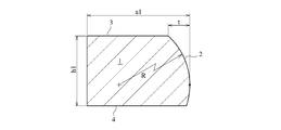
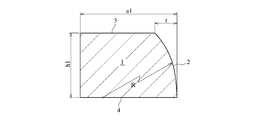
- FIG. 1 to 4 show a section of a piston ring (1) having an axial width (h1) and a radial thickness (a1) according to an embodiment of the present invention.
- the cross section is a cross section parallel to the central axis passing through the central axis of the piston ring (1), and the outer peripheral sliding surface includes an outwardly convex first curved surface (2).
- the first curved surface (2) has a curvature radius (R) continuously increasing from the crank chamber side (lower part of the figure) to the combustion chamber side (upper part of the figure) (the first piston ring of the present invention). ) Or decreased (second piston ring of the present invention).
- the radius of curvature of the first curved surface (2) on the combustion chamber side is increased, and the first curved surface (2) is in sliding contact with the cylinder wall on the combustion chamber side of the first curved surface (2).
- the contact Hertz stress due to the ring load can be reduced, and as a result, the PV value (product of the surface pressure P and the piston speed V) can be reduced, and scuffing can be avoided.
- the first curved surface (2) has a small radius of curvature on the combustion chamber side, a large radial retreat amount (t), and a combustion in which the maximum pressure in the cylinder is loaded. Edge loading during the process can be avoided.
- the involute curve refers to the trajectory drawn by the end points of the yarn as it is unwound while tightly winding the yarn wrapped around a circle.
- the above curve is deformed using parameters a, b, ⁇ , and ⁇ .
- the x axis is set to the a1 direction (direction perpendicular to the ring axis), and the y axis is set to the h1 direction (ring axis direction).
- a curve can be drawn in which the radius of curvature continuously increases or decreases with the vertex of the first curved surface (2) as the origin.
- the curve clearly expressed by the mathematical formula as described above, when forming the first curved surface, enables processing by numerical control and molding processing by a grindstone having a shape formed by numerical control, thus facilitating manufacture, Improve manufacturing quality.
- FIGS. 2 to 4 show a piston ring according to an embodiment different from FIG. 1 of the present invention.
- the outer peripheral sliding surface is composed only of the first curved surface, and the vertex (2) of the first curved surface is located between the upper side surface and the lower side surface in FIG. In 2, it is located at the lower side edge.
- 3 has chamfered portions (5, 5) between the first curved surface (2) and the combustion chamber side upper side surface (3) and the crank chamber side lower side surface (4), respectively.
- the vertex of the first curved surface is preferably located closer to the crank chamber than the center position in the axial width.
- the receding amount (t) of the outer peripheral sliding surface on the combustion chamber side is preferably 0.001% or more and 0.015% or less of the nominal diameter (d1) of the piston ring.
- the retraction amount (t) is more preferably 0.004% or more, and in the case of the second piston ring, the retraction amount (t) is more preferably 0.01 or less, and 0.007% or less. More preferably.
- the piston ring of the present invention can be preferably used in a large diesel engine having a large maximum pressure in the cylinder and a nominal diameter of 200 mm or more and less than 1100 mm, but if the outer peripheral sliding surface satisfies a predetermined shape, the applicable engine can be used. Without limitation, it can also be used for medium-sized diesel engines with a nominal diameter of less than 200 mm.
- the base material of the piston ring of the present invention can be applied to either cast iron or steel, but it is effective for high power and high efficiency. It is preferable to do.
- the steel material is applied to the base material, it is preferably a steel selected from carbon steel, low alloy steel, spring steel, bearing steel, and martensitic stainless steel.
- High carbon steel with C of about 0.6 to 0.8 mass% for carbon steel, SUP9, SUP10, SUP12 etc. for spring steel, SUJ2 for bearing steel, SUS420J2 or SUS440B for martensitic stainless steel Is done.
- a steel material suitable for required characteristics such as high-temperature strength, thermal conductivity, and heat resistance is selected.
- the piston ring of the present invention preferably has one or more coatings selected from the group consisting of a nitride coating, a plating coating, a thermal spray coating, a chemical conversion coating, and an ion plating coating.
- Plating coating includes hard chrome plating coating, multilayer chrome plating coating, nickel composite plating coating, thermal spray coating includes molybdenum spray coating and cermet spray coating, and ion plating coating includes CrN coating and TiN coating. It is.
- Example 1 (first piston ring) The material composition is mass%, C: 0.48%, Si: 0.21%, Mn: 0.79%, Cr: 1.02%, V: 0.22%.
- a cylindrical material was prepared by machining and machined to produce a steel top ring with a rectangular cross section having a nominal diameter (d1) of 330 mm, a width (h1) of 5 mm, and a thickness (a1) of 9 mm.
- a nitride layer of about 70 ⁇ m is formed on the entire ring surface by gas nitriding at 460 ° C. for 5 hours, and the outer periphery mainly comprises composite particles in which fine Cr carbide particles are dispersed in a Ni alloy matrix by high-speed flame spraying.
- a cermet sprayed coating having a constituent particle (SM5241 powder from Sulzer Metco Co., Ltd.) was formed to a thickness of about 500 ⁇ m, and final polishing was performed to a final coating thickness of about 350 ⁇ m.
- the compound layer (white layer) formed on the surface by gas nitriding was removed by grinding.
- the coordinate axis of the deformed involute curve is appropriately rotated and translated so that the vertex of the first curved surface (with a distance of 3.5 mm from the combustion chamber side upper surface) is the origin of the coordinate axis. I draw.
- the radius of curvature at a position 0.5 mm from the lower side is 70 mm
- the radius of curvature at the apex position is 300 mm
- the radius of curvature at a position 0.5 mm from the upper side is 460 mm.
- a first grindstone was formed using this shaped grinding wheel, and 0.5 mm from the top and bottom sides was chamfered to complete finish polishing.
- the retreat amount (t) of the outer peripheral sliding surface on the combustion chamber side was 0.009 mm, which was 0.002% of the nominal diameter (d1).
- a steel top ring was produced.
- the radius of curvature at a position 0.5 mm from the lower side is 340 mm
- the radius of curvature at the apex position is 270 mm
- the radius of curvature at a position 0.5 mm from the upper side is 100 mm.
- the retreat amount (t) of the outer peripheral sliding surface on the combustion chamber side was 0.016 mm, which was 0.0048% of the nominal diameter (d1). Further, as a result of conducting an actual machine test similar to that in Example 1, there was no trouble in any of the cylinders, and there was no abnormality in the sliding surface of the top ring.
- Example 3-5 (first piston ring) Steel top rings of Examples 3 to 5 were produced in the same manner as in Example 1 except that the parameters a, b, ⁇ , and ⁇ of the modified involute curve were changed to the values shown in Table 1.
- Example 1 to Example 5 are also shown in Example 1 for the lower radius side (position 0.5 mm from the lower side), the apex position, the curvature radius on the upper side side (position 0.5 mm from the upper side), and the retreat amount (t). It is shown in Table 1 together with the results of 1 and 2.
- the amount of retreat means the amount of retreat (t) of the outer peripheral sliding surface on the combustion chamber side.
- Example 6 (first piston ring) Material composition is mass%, C: 3.7%, Si: 2.7%, Mn: 0.6%, P: 0.04%, S: 0.01%, Cr: 0.10%, Ni: 0.90%, V: 0.07%, Cu: 2.39% cast iron was melted, cast, and machined to produce a CV graphite cast iron top ring with a nominal diameter (d1) of 330 mm, width (h1) of 7 mm, and thickness (a1) of 10 mm.
- the coordinate axis of the modified involute curve is appropriately rotated and drawn in parallel.
- the radius of curvature at a position 0.5 mm from the lower surface is 65 mm
- the radius of curvature at the apex position is 280 mm
- the radius of curvature at a position 0.5 mm from the upper surface is 450 mm.
- a first grindstone was formed using this shaped grinding wheel, and 0.5 mm from the top and bottom sides was chamfered to complete finish polishing.
- the retreat amount (t) of the outer peripheral sliding surface on the combustion chamber side was 0.024 mm, which was 0.007% of the nominal diameter (d1).
- a CV graphite cast iron top ring was produced.
- the radius of curvature at a position 0.5 mm from the lower side is 360 mm
- the radius of curvature at the apex position is 300 mm
- the radius of curvature at a position 0.5 mm from the upper side is 50 mm.
- the retreat amount (t) of the outer peripheral sliding surface on the combustion chamber side was 0.035 mm, which was 0.011% of the nominal diameter (d1).
Abstract
Description
x = a(cosθ+θb・sinθ)/α、
y = a(sinθ-θ/cosθ)/β、
a、b、α、βは定数、
なる関係式を用いて表されることがより好ましい。
x = cosθ+θsinθ
y = sinθ-θcosθ
で表されるが、本発明のピストンリングの外周摺動面の第1の曲面(2)に適した曲率変化とするためには、上記曲線をパラメータa、b、α、βを用いて変形し、
x = a(cosθ+θb・sinθ)/α
y = a(sinθ-θ/cosθ)/β
a、b、α、βは定数
なる関係式で表される曲線(変形インボリュート曲線)を用いることが好ましい。ここで、a、b、α、βは適用するピストンリングに応じて適宜設定できるが、aは3000~10000、bは2~3、αは1~2、βは1~5とすることが好ましい。上記関係式の座標軸を所定量回転し、且つ所定量平行移動し、又は反転することにより、例えばx軸をa1方向(リング軸に垂直な方向)、y軸をh1方向(リング軸方向)として、第1の曲面(2)の頂点を原点とし、曲率半径が連続的に増加又は減少する曲線を描くことができる。
材料組成が、質量%で、C:0.48%、Si:0.21%、Mn:0.79%、Cr:1.02%、V:0.22%で、外径110 mm、長さ200 mmの棒鋼から、リングローリング加工により筒状素材を作製し、機械加工を施し、呼び径(d1)330 mm、幅(h1)5 mm、厚さ(a1)9mmの矩形断面の鋼製トップリングを作製した。次に、460℃、5時間のガス窒化によりリング全面に窒化層を約70μm形成し、さらに外周には、高速フレーム溶射によりNi合金基地中に微細なCr炭化物粒子が分散した複合材粒子を主たる構成粒子(スルザーメテコ社のSM5241粉末)とするサーメット溶射皮膜を約500μm形成し、最終的には溶射皮膜の膜厚約350μmまで仕上研磨を施した。ここで、ガス窒化により表面に生成した化合物層(白層)は研削除去した。
x = a(cosθ+θb・sinθ)/α
y = a(sinθ-θ/cosθ)/β
a = 7000、b = 3、α= 1、β= 2
なる変形インボリュート曲線を用い、第1の曲面の頂点(燃焼室側上側面から3.5 mmの距離とした)が座標軸の原点となるように、上記変形インボリュート曲線の座標軸を適宜回転させ、平行移動して描いている。また、この場合、下側面から0.5 mmの位置の曲率半径が70 mm、頂点位置の曲率半径が300 mm、上側面から0.5 mmの位置の曲率半径が460 mmとなる。この形状に成形した成形砥石を用いて、第1の曲面を形成し、上下側面から0.5 mmの領域は面取り加工を施し、仕上研磨を完了した。また、燃焼室側の外周摺動面の後退量(t)は0.009 mmで、呼び径(d1)の0.002%であった。
実機試験は、ボア径330 mmの6気筒4ストローク中速ディーゼルエンジンの試験機において、6気筒全てに実施例1のトップリングを装着したピストンを使用して行った。トップリング以外は、従来から使用されてきたピストンリングを使用した。300時間の運転中はスカッフ等のトラブルは無く、トップリングを取り出して摺動面を観察した結果も特に異常はなかった。
変形インボリュート曲線のパラメータをa = 6000、b = 3、α= 1、β= 1.5とし、第1の曲面を曲率半径がクランク室側から燃焼室側に減少するように反転して形成した以外は、実施例1と同様にして、鋼製トップリングを作製した。この場合、下側面から0.5 mmの位置の曲率半径が340 mm、頂点位置の曲率半径が270 mm、上側面から0.5 mmの位置の曲率半径が100 mmとなる。燃焼室側の外周摺動面の後退量(t)は0.016 mmで、呼び径(d1)の0.0048%であった。さらに、実施例1と同様な実機試験を行った結果、いずれの気筒においてもトラブルは無く、またトップリングの摺動面も異常はなかった。
変形インボリュート曲線のパラメータa、b、α、βを表1に示す値とした以外は実施例1と同様にして実施例3~5の鋼製トップリングを作製した。実施例3~5の下側面側(下側面から0.5 mmの位置)、頂点位置、上側面側(上側面から0.5 mmの位置)における曲率半径と、後退量(t)についても、実施例1及び2の結果とともに表1に示す。さらに、実施例3~5のトップリングを2気筒ずつ装着して実施例1と同様に実機試験を行った結果、いずれのトップリングを使用した気筒においてもトラブルは無く、またトップリングの摺動面も異常はなかった。

材料組成が、質量%で、C:3.7%、Si:2.7%、Mn:0.6%、P:0.04%、S:0.01%、Cr:0.10%、Ni:0.90%、V:0.07%、Cu:2.39%の鋳鉄を溶解、鋳造、機械加工して、呼び径(d1)330 mm、幅(h1)7 mm、厚さ(a1)10 mmの矩形断面のCV黒鉛鋳鉄製トップリングを作製した。変形インボリュート曲線のパラメータをa = 6000、b = 3、α= 1、β= 1.7として、燃焼室側上側面から4.5 mmの距離とした第1の曲面の頂点が座標軸の原点となるように、上記変形インボリュート曲線の座標軸を適宜回転させ、平行移動して描いている。また、この場合、下側面から0.5 mmの位置の曲率半径が65 mm、頂点位置の曲率半径が280 mm、上側面から0.5 mmの位置の曲率半径が450 mmとなる。この形状に成形した成形砥石を用いて、第1の曲面を形成し、上下側面から0.5 mmの領域は面取り加工を施し、仕上研磨を完了した。また、燃焼室側の外周摺動面の後退量(t)は0.024 mmで、呼び径(d1)の0.007%であった。
変形インボリュート曲線のパラメータをa = 3000、b = 3、α= 1、β= 2とし、第1の曲面を曲率半径がクランク室側から燃焼室側に減少するように反転して形成した以外は、実施例6と同様にして、CV黒鉛鋳鉄製トップリングを作製した。この場合、下側面から0.5 mmの位置の曲率半径が360 mm、頂点位置の曲率半径が300 mm、上側面から0.5 mmの位置の曲率半径が50 mmとなる。燃焼室側の外周摺動面の後退量(t)は0.035 mmで、呼び径(d1)の0.011%であった。
Claims (7)
- ピストンリングの中心軸を通り前記中心軸に平行な断面に現れる外周摺動面の第1の曲面が外に凸であって、前記第1の曲面の曲率半径がクランク室側から燃焼室側に連続的に増加又は減少していることを特徴とするピストンリング。
- 請求項1に記載のピストンリングにおいて、前記断面に現れる前記第1の曲面の頂点が軸方向幅の中央位置よりクランク室側に位置することを特徴とするピストンリング。
- 請求項1又は2に記載のピストンリングにおいて、前記第1の曲面の前記断面に現れる曲線がインボリュート曲線を変形した曲線で表されることを特徴とするピストンリング。
- 請求項3に記載のピストンリングにおいて、前記曲線が
x = a(cosθ+θb・sinθ)/α
y = a(sinθ-θ/cosθ)/β
a、b、α、βは定数
なる関係式を用いて表されることを特徴とするピストンリング。 - 請求項1~4のいずれかに記載のピストンリングにおいて、前記第1の曲面と燃焼室側上側面及びクランク室側下側面の間それぞれに面取り部を有することを特徴とするピストンリング。
- 請求項1~4のいずれかに記載のピストンリングにおいて、前記第1の曲面と燃焼室側上側面及びクランク室側下側面の間それぞれに外に凸の第2及び第3の曲面を有することを特徴とするピストンリング。
- 請求項1~6のいずれかに記載のピストンリングにおいて、前記断面に現れる前記第1の曲面の頂点から燃焼室側端までの半径方向の後退量(t)が、ピストンリングの呼び径(d1)の0.001%以上0.015%以下であることを特徴とするピストンリング。
Priority Applications (3)
| Application Number | Priority Date | Filing Date | Title |
|---|---|---|---|
| EP15811150.0A EP3163129B1 (en) | 2014-06-27 | 2015-06-25 | Piston ring |
| KR1020177002115A KR102426972B1 (ko) | 2014-06-27 | 2015-06-25 | 피스톤 링 |
| CN201580034275.XA CN106662246B (zh) | 2014-06-27 | 2015-06-25 | 活塞环 |
Applications Claiming Priority (4)
| Application Number | Priority Date | Filing Date | Title |
|---|---|---|---|
| JP2014-132184 | 2014-06-27 | ||
| JP2014132185A JP6446188B2 (ja) | 2014-06-27 | 2014-06-27 | ピストンリング |
| JP2014132184A JP6446187B2 (ja) | 2014-06-27 | 2014-06-27 | ピストンリング |
| JP2014-132185 | 2014-06-27 |
Publications (2)
| Publication Number | Publication Date |
|---|---|
| WO2015199183A1 true WO2015199183A1 (ja) | 2015-12-30 |
| WO2015199183A9 WO2015199183A9 (ja) | 2016-09-01 |
Family
ID=54938260
Family Applications (1)
| Application Number | Title | Priority Date | Filing Date |
|---|---|---|---|
| PCT/JP2015/068368 WO2015199183A1 (ja) | 2014-06-27 | 2015-06-25 | ピストンリング |
Country Status (4)
| Country | Link |
|---|---|
| EP (1) | EP3163129B1 (ja) |
| KR (1) | KR102426972B1 (ja) |
| CN (1) | CN106662246B (ja) |
| WO (1) | WO2015199183A1 (ja) |
Cited By (2)
| Publication number | Priority date | Publication date | Assignee | Title |
|---|---|---|---|---|
| US20180187780A1 (en) * | 2015-07-09 | 2018-07-05 | Kabushiki Kaisha Riken | Piston ring for combustion engine |
| CN110506173A (zh) * | 2017-03-30 | 2019-11-26 | 株式会社理研 | 内燃机用活塞和活塞环 |
Families Citing this family (6)
| Publication number | Priority date | Publication date | Assignee | Title |
|---|---|---|---|---|
| DE102018107793A1 (de) * | 2018-04-03 | 2019-10-10 | Federal-Mogul Burscheid Gmbh | Kolbenring und Kolbenring/Kolben-Kombination mit verbesserten Verschleißeigenschaften |
| DE102018120962A1 (de) * | 2018-08-13 | 2020-02-13 | Federal-Mogul Burscheid Gmbh | Dreiteiliger Ölabstreifring |
| CN110332056A (zh) * | 2019-06-18 | 2019-10-15 | 安庆帝伯格茨活塞环有限公司 | 一种低摩擦低油耗发动机活塞环组及机构 |
| CN111075598B (zh) * | 2019-12-28 | 2021-03-16 | 潍柴动力股份有限公司 | 一种活塞环、活塞组件及发动机 |
| CN112377614B (zh) | 2020-11-11 | 2023-02-24 | 马勒汽车技术(中国)有限公司 | 用于发动机的活塞环及活塞环的加工方法 |
| CN115653749B (zh) * | 2022-09-20 | 2023-08-29 | 上汽通用五菱汽车股份有限公司 | 曲轴连杆组件、发动机及汽车 |
Citations (2)
| Publication number | Priority date | Publication date | Assignee | Title |
|---|---|---|---|---|
| JPH06185620A (ja) * | 1992-12-18 | 1994-07-08 | Honda Motor Co Ltd | ピストンリング |
| JP2005273583A (ja) * | 2004-03-25 | 2005-10-06 | Toyota Motor Corp | ピストンリング |
Family Cites Families (25)
| Publication number | Priority date | Publication date | Assignee | Title |
|---|---|---|---|---|
| GB327213A (en) * | 1929-01-12 | 1930-04-03 | William Arthur Oubridge | Manufacture of piston rings |
| GB327589A (en) * | 1929-04-19 | 1930-04-10 | William Arthur Oubridge | Manufacture of piston rings |
| DE1021666B (de) | 1956-07-04 | 1957-12-27 | Teves Kg Alfred | Selbstspannender Ring, insbesondere Kolbenring |
| US4462771A (en) * | 1981-02-09 | 1984-07-31 | The Trane Company | Wrap element and tip seal for use in fluid apparatus of the scroll type and method for making same |
| JPS57144350A (en) * | 1981-02-26 | 1982-09-06 | Nippon Piston Ring Co Ltd | Piston ring |
| JPS57196238U (ja) | 1981-06-08 | 1982-12-13 | ||
| SU1511502A1 (ru) | 1986-11-14 | 1989-09-30 | Завод-втуз при Московском автомобильном заводе им.И.А.Лихачева | Уплотнительное устройство дл наружного давлени |
| DE3940301A1 (de) * | 1989-12-06 | 1991-06-13 | Friedhelm Stecher | Kolbenring |
| US5695199A (en) | 1994-03-14 | 1997-12-09 | Rao; V. Durga Nageswar | Piston sealing assembly |
| DE4429649C2 (de) * | 1994-08-20 | 1998-02-19 | Ae Goetze Gmbh | Kolbenring |
| JP2002039384A (ja) | 2000-07-28 | 2002-02-06 | Nippon Piston Ring Co Ltd | ピストンリング |
| DE10340313A1 (de) | 2003-09-02 | 2005-05-19 | Mahle Gmbh | Ölabstreifring-Ringnut-Anordnung für Kolben von Verbrennungsmotoren |
| JP2005264978A (ja) * | 2004-03-16 | 2005-09-29 | Toyota Motor Corp | 圧力リング |
| JP4452652B2 (ja) | 2005-06-01 | 2010-04-21 | トヨタ自動車株式会社 | ピストンリング |
| JP2006337164A (ja) * | 2005-06-01 | 2006-12-14 | Toyota Motor Corp | 摺動面形状測定方法 |
| CN1932270A (zh) * | 2005-09-13 | 2007-03-21 | 瓦特西拉瑞士股份有限公司 | 活塞环组件 |
| JP2007224939A (ja) * | 2006-02-21 | 2007-09-06 | Daihatsu Motor Co Ltd | 二サイクル内燃機関用ピストンリング |
| BRPI0605175B1 (pt) | 2006-12-05 | 2020-01-21 | Mahle Metal Leve S/A | anel de pistão para motores de combustão interna |
| JP2009091927A (ja) * | 2007-10-05 | 2009-04-30 | Mitsubishi Heavy Ind Ltd | 往復動機関のピストンリング |
| JP2010031835A (ja) | 2008-06-23 | 2010-02-12 | Nissan Motor Co Ltd | 内燃機関用オイルリング及びピストン |
| WO2011064888A1 (ja) | 2009-11-30 | 2011-06-03 | 日本ピストンリング株式会社 | ピストンリング |
| JP2011169388A (ja) | 2010-02-18 | 2011-09-01 | Teikoku Piston Ring Co Ltd | ピストンリング |
| DE102010047836B4 (de) * | 2010-10-07 | 2014-09-04 | Federal-Mogul Burscheid Gmbh | Verfahren zur Herstellung eines Kolbenrings |
| DE102012000241B4 (de) * | 2011-05-10 | 2016-12-08 | Federal-Mogul Burscheid Gmbh | Kolbenring für 2-Taktmotoren |
| DE102012013803A1 (de) | 2012-04-19 | 2013-10-24 | Federal-Mogul Burscheid Gmbh | Kolbenring für eine Brennkraftmaschine |
-
2015
- 2015-06-25 KR KR1020177002115A patent/KR102426972B1/ko active IP Right Grant
- 2015-06-25 CN CN201580034275.XA patent/CN106662246B/zh active Active
- 2015-06-25 WO PCT/JP2015/068368 patent/WO2015199183A1/ja active Application Filing
- 2015-06-25 EP EP15811150.0A patent/EP3163129B1/en not_active Revoked
Patent Citations (2)
| Publication number | Priority date | Publication date | Assignee | Title |
|---|---|---|---|---|
| JPH06185620A (ja) * | 1992-12-18 | 1994-07-08 | Honda Motor Co Ltd | ピストンリング |
| JP2005273583A (ja) * | 2004-03-25 | 2005-10-06 | Toyota Motor Corp | ピストンリング |
Non-Patent Citations (1)
| Title |
|---|
| See also references of EP3163129A4 * |
Cited By (2)
| Publication number | Priority date | Publication date | Assignee | Title |
|---|---|---|---|---|
| US20180187780A1 (en) * | 2015-07-09 | 2018-07-05 | Kabushiki Kaisha Riken | Piston ring for combustion engine |
| CN110506173A (zh) * | 2017-03-30 | 2019-11-26 | 株式会社理研 | 内燃机用活塞和活塞环 |
Also Published As
| Publication number | Publication date |
|---|---|
| KR102426972B1 (ko) | 2022-07-29 |
| CN106662246A (zh) | 2017-05-10 |
| EP3163129A1 (en) | 2017-05-03 |
| WO2015199183A9 (ja) | 2016-09-01 |
| EP3163129B1 (en) | 2020-10-14 |
| KR20170024018A (ko) | 2017-03-06 |
| CN106662246B (zh) | 2018-09-14 |
| EP3163129A4 (en) | 2018-03-21 |
Similar Documents
| Publication | Publication Date | Title |
|---|---|---|
| WO2015199183A1 (ja) | ピストンリング | |
| US7383807B2 (en) | Coated power cylinder components for diesel engines | |
| JP6112203B2 (ja) | 鉄系溶射被膜、これを用いた内燃機関用シリンダーブロック及び内燃機関用摺動機構 | |
| WO2012067084A1 (ja) | ピストンリング | |
| WO2020022032A1 (ja) | 鋳鉄製シリンダライナおよび内燃機関 | |
| CN103998755A (zh) | 通过微细凹凸的最佳配置而改善了耐磨损性的气缸装置 | |
| JP2010236444A (ja) | シリンダとピストンの組み合わせ | |
| JP6446188B2 (ja) | ピストンリング | |
| JP6446187B2 (ja) | ピストンリング | |
| US11098674B2 (en) | Piston for a heat engine, heat engine comprising such a piston, and methods | |
| JP2017026054A (ja) | ピストンリング | |
| Igartua et al. | Tribological tests to simulate wear on piston rings | |
| CN111173642A (zh) | 一种密封效果好的活塞环 | |
| US20240110625A1 (en) | Compression Ring | |
| CN216111036U (zh) | 一种活塞环及甲醇发动机 | |
| CN218493692U (zh) | 一种用于无缸套柴油机的活塞环组 | |
| WO2023013264A1 (ja) | オイルリング | |
| US20230008886A1 (en) | Coated piston ring for an internal combustion engine | |
| JP2516978Y2 (ja) | シリンダとピストンリングの組合せ | |
| US20200040996A1 (en) | Piston ring for internal combustion engines | |
| JP2023125757A (ja) | ピストンリング | |
| JPH0723649Y2 (ja) | シリンダとピストンリングの組合せ | |
| JPS6229749A (ja) | 内燃機関の摺動部の構造 | |
| CN205532915U (zh) | 一种外圆超硬活塞环 | |
| JP2024003920A (ja) | 往復動機関のシリンダブロック、シリンダ用摺動部材 |
Legal Events
| Date | Code | Title | Description |
|---|---|---|---|
| 121 | Ep: the epo has been informed by wipo that ep was designated in this application |
Ref document number: 15811150 Country of ref document: EP Kind code of ref document: A1 |
|
| NENP | Non-entry into the national phase |
Ref country code: DE |
|
| REEP | Request for entry into the european phase |
Ref document number: 2015811150 Country of ref document: EP |
|
| WWE | Wipo information: entry into national phase |
Ref document number: 2015811150 Country of ref document: EP |
|
| ENP | Entry into the national phase |
Ref document number: 20177002115 Country of ref document: KR Kind code of ref document: A |