WO2015198728A1 - 撮像装置およびカプセル内視鏡 - Google Patents
撮像装置およびカプセル内視鏡 Download PDFInfo
- Publication number
- WO2015198728A1 WO2015198728A1 PCT/JP2015/063581 JP2015063581W WO2015198728A1 WO 2015198728 A1 WO2015198728 A1 WO 2015198728A1 JP 2015063581 W JP2015063581 W JP 2015063581W WO 2015198728 A1 WO2015198728 A1 WO 2015198728A1
- Authority
- WO
- WIPO (PCT)
- Prior art keywords
- image
- resolution
- unit
- change amount
- threshold
- Prior art date
- Legal status (The legal status is an assumption and is not a legal conclusion. Google has not performed a legal analysis and makes no representation as to the accuracy of the status listed.)
- Ceased
Links
Images



Classifications
-
- G—PHYSICS
- G02—OPTICS
- G02B—OPTICAL ELEMENTS, SYSTEMS OR APPARATUS
- G02B23/00—Telescopes, e.g. binoculars; Periscopes; Instruments for viewing the inside of hollow bodies; Viewfinders; Optical aiming or sighting devices
- G02B23/24—Instruments or systems for viewing the inside of hollow bodies, e.g. fibrescopes
- G02B23/2476—Non-optical details, e.g. housings, mountings, supports
- G02B23/2484—Arrangements in relation to a camera or imaging device
-
- A—HUMAN NECESSITIES
- A61—MEDICAL OR VETERINARY SCIENCE; HYGIENE
- A61B—DIAGNOSIS; SURGERY; IDENTIFICATION
- A61B1/00—Instruments for performing medical examinations of the interior of cavities or tubes of the body by visual or photographical inspection, e.g. endoscopes; Illuminating arrangements therefor
- A61B1/00002—Operational features of endoscopes
- A61B1/00004—Operational features of endoscopes characterised by electronic signal processing
- A61B1/00006—Operational features of endoscopes characterised by electronic signal processing of control signals
-
- A—HUMAN NECESSITIES
- A61—MEDICAL OR VETERINARY SCIENCE; HYGIENE
- A61B—DIAGNOSIS; SURGERY; IDENTIFICATION
- A61B1/00—Instruments for performing medical examinations of the interior of cavities or tubes of the body by visual or photographical inspection, e.g. endoscopes; Illuminating arrangements therefor
- A61B1/00002—Operational features of endoscopes
- A61B1/00004—Operational features of endoscopes characterised by electronic signal processing
- A61B1/00009—Operational features of endoscopes characterised by electronic signal processing of image signals during a use of endoscope
-
- A—HUMAN NECESSITIES
- A61—MEDICAL OR VETERINARY SCIENCE; HYGIENE
- A61B—DIAGNOSIS; SURGERY; IDENTIFICATION
- A61B1/00—Instruments for performing medical examinations of the interior of cavities or tubes of the body by visual or photographical inspection, e.g. endoscopes; Illuminating arrangements therefor
- A61B1/00002—Operational features of endoscopes
- A61B1/00011—Operational features of endoscopes characterised by signal transmission
- A61B1/00016—Operational features of endoscopes characterised by signal transmission using wireless means
-
- A—HUMAN NECESSITIES
- A61—MEDICAL OR VETERINARY SCIENCE; HYGIENE
- A61B—DIAGNOSIS; SURGERY; IDENTIFICATION
- A61B1/00—Instruments for performing medical examinations of the interior of cavities or tubes of the body by visual or photographical inspection, e.g. endoscopes; Illuminating arrangements therefor
- A61B1/04—Instruments for performing medical examinations of the interior of cavities or tubes of the body by visual or photographical inspection, e.g. endoscopes; Illuminating arrangements therefor combined with photographic or television appliances
- A61B1/041—Capsule endoscopes for imaging
-
- A—HUMAN NECESSITIES
- A61—MEDICAL OR VETERINARY SCIENCE; HYGIENE
- A61B—DIAGNOSIS; SURGERY; IDENTIFICATION
- A61B1/00—Instruments for performing medical examinations of the interior of cavities or tubes of the body by visual or photographical inspection, e.g. endoscopes; Illuminating arrangements therefor
- A61B1/04—Instruments for performing medical examinations of the interior of cavities or tubes of the body by visual or photographical inspection, e.g. endoscopes; Illuminating arrangements therefor combined with photographic or television appliances
- A61B1/045—Control thereof
-
- H—ELECTRICITY
- H04—ELECTRIC COMMUNICATION TECHNIQUE
- H04N—PICTORIAL COMMUNICATION, e.g. TELEVISION
- H04N23/00—Cameras or camera modules comprising electronic image sensors; Control thereof
- H04N23/60—Control of cameras or camera modules
- H04N23/62—Control of parameters via user interfaces
-
- H—ELECTRICITY
- H04—ELECTRIC COMMUNICATION TECHNIQUE
- H04N—PICTORIAL COMMUNICATION, e.g. TELEVISION
- H04N23/00—Cameras or camera modules comprising electronic image sensors; Control thereof
- H04N23/60—Control of cameras or camera modules
- H04N23/65—Control of camera operation in relation to power supply
- H04N23/651—Control of camera operation in relation to power supply for reducing power consumption by affecting camera operations, e.g. sleep mode, hibernation mode or power off of selective parts of the camera
-
- H—ELECTRICITY
- H04—ELECTRIC COMMUNICATION TECHNIQUE
- H04N—PICTORIAL COMMUNICATION, e.g. TELEVISION
- H04N23/00—Cameras or camera modules comprising electronic image sensors; Control thereof
- H04N23/60—Control of cameras or camera modules
- H04N23/667—Camera operation mode switching, e.g. between still and video, sport and normal or high- and low-resolution modes
-
- H—ELECTRICITY
- H04—ELECTRIC COMMUNICATION TECHNIQUE
- H04N—PICTORIAL COMMUNICATION, e.g. TELEVISION
- H04N25/00—Circuitry of solid-state image sensors [SSIS]; Control thereof
- H04N25/40—Extracting pixel data from image sensors by controlling scanning circuits, e.g. by modifying the number of pixels sampled or to be sampled
-
- H—ELECTRICITY
- H04—ELECTRIC COMMUNICATION TECHNIQUE
- H04N—PICTORIAL COMMUNICATION, e.g. TELEVISION
- H04N25/00—Circuitry of solid-state image sensors [SSIS]; Control thereof
- H04N25/40—Extracting pixel data from image sensors by controlling scanning circuits, e.g. by modifying the number of pixels sampled or to be sampled
- H04N25/42—Extracting pixel data from image sensors by controlling scanning circuits, e.g. by modifying the number of pixels sampled or to be sampled by switching between different modes of operation using different resolutions or aspect ratios, e.g. switching between interlaced and non-interlaced mode
-
- H—ELECTRICITY
- H04—ELECTRIC COMMUNICATION TECHNIQUE
- H04N—PICTORIAL COMMUNICATION, e.g. TELEVISION
- H04N23/00—Cameras or camera modules comprising electronic image sensors; Control thereof
- H04N23/50—Constructional details
- H04N23/555—Constructional details for picking-up images in sites, inaccessible due to their dimensions or hazardous conditions, e.g. endoscopes or borescopes
Definitions
- the present invention relates to an imaging device and a capsule endoscope which can change the resolution of an image.
- Priority is claimed on Japanese Patent Application No. 2014-128040, filed on June 23, 2014, the content of which is incorporated herein by reference.
- subjects other than important subjects may affect the amount of change in information of an image.
- the wind may cause the branches to move and the leaves to move, which may increase the amount of information change in the image.
- a high resolution may be set even if the information change amount of the important subject is not large.
- An object of the present invention is to provide an imaging device and a capsule endoscope which can reduce the influence of subjects other than important subjects on resolution control.
- an imaging device performs imaging continuously and generates an image of a plurality of frames whose resolution is any of a plurality of resolutions, and information of the images of the plurality of frames
- a first change amount calculation unit that calculates a first change amount that is a change amount
- a second change amount calculation unit that calculates a second change amount that is a time change amount of the first change amount
- a control unit configured to control the resolution of the imaging unit based on a result of comparing the second change amount and a threshold.
- the imaging unit is configured to generate a first pixel signal based on incident light, and a plurality of pixels and the plurality of pixels.
- the plurality of first storage units for storing the output first pixel signals, and the images of the plurality of frames formed by the first pixel signals stored in the plurality of first storage units are output.
- a plurality of second storage units for storing a second pixel signal obtained by adding a plurality of first pixel signals output from the plurality of pixels, and a plurality of second storage units
- a second output unit configured to output the images of the plurality of frames formed by the second pixel signals stored in the second storage unit.
- the control unit compares the amount of information of the image with a first threshold, and the second amount of change.
- the resolution of the imaging unit may be controlled based on the result of comparing the second threshold with the second threshold.
- a capsule endoscope has an imaging device according to the first aspect.
- the first change amount which is the information change amount of the image is calculated, and the second change amount which is the time change amount of the first change amount is calculated.
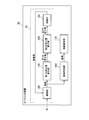
- FIG. 1 shows the configuration of an imaging device 10 according to the present embodiment.
- the imaging device 10 includes an imaging unit 100, a first change amount calculation unit 110, a second change amount calculation unit 120, and a control unit 130.
- the imaging unit 100 continuously performs imaging, and generates images (image signals) of a plurality of frames whose resolution is any of a plurality of resolutions. It is possible to set any one of a plurality of resolutions for the imaging unit 100. In addition, it is possible to change the resolution set in the imaging unit 100.
- the first change amount calculation unit 110 calculates a first change amount which is an information change amount of images of a plurality of frames.
- the first change amount is the sum of absolute differences of image signals in images of two frames captured at different times.
- the first change amount may be a sum of absolute differences of information amounts (feature amounts) generated from image signals in images of two frames captured at different times.
- the first change amount calculation unit 110 calculates a first change amount of images of two consecutive frames.
- the first change amount calculation unit 110 may calculate a first change amount between an image of n (n is a natural number) frame and an image of n + k frame for every k (k is a natural number of 2 or more) frames.
- the first change amount calculation unit 110 may have a storage unit that stores images of a plurality of frames. Alternatively, a storage unit that stores the image output from the imaging unit 100 may be provided separately from the first change amount calculation unit 110.
- the second change amount calculation unit 120 calculates a second change amount that is a time change amount of the first change amount. For example, the second change amount calculation unit 120 calculates a second change amount from the two first change amounts calculated continuously. In order to facilitate the processing performed by the control unit 130, the second change amount may be an absolute value of the time change amount. If the second change amount is an absolute value, the imaging device 10 holds the sign (positive or negative) of the second change amount together with the second change amount.
- the control unit 130 controls the resolution of the imaging unit 100 based on the result of comparing the second change amount and the threshold. For example, when the second change amount is less than the threshold, the control unit 130 sets the resolution of the imaging unit 100 to the first resolution. When the second change amount is equal to or more than the threshold, the control unit 130 sets the resolution of the imaging unit 100 to a second resolution higher than the first resolution. It is desirable that the control unit 130 control the resolution of the imaging unit 100 based on the result of comparing the second change amount and the threshold value and the result of determining the sign of the second change amount.
- FIG. 2A shows the processing result of the imaging device 10.
- FIG. 2B shows the processing result of the conventional imaging device.
- the horizontal axes of the graphs in FIGS. 2A and 2B indicate time.
- the vertical axis of the graph in FIG. 2A indicates the absolute value of the second variation.
- the vertical axis of the graph in FIG. 2B indicates the information change amount of the image.
- FIG. 2A and FIG. 2B show processing results in the case where the amount of information of only important subjects changes. For example, there is a branch of a tree with many leaves in the background of an important subject, and the processing result when the branch and the leaf do not move is the processing result shown in FIGS. 2A and 2B.
- the control unit 130 is in one of two states, the low resolution setting state and the high resolution setting state, and repeatedly compares the absolute value of the second change amount with the threshold. . In the comparison up to the timing T11, it is determined that the absolute value of the second change amount is less than the threshold. As a result, the control unit 130 is in the low resolution setting state until the timing T11, and the resolution of the imaging unit 100 is set to the low resolution. The low resolution setting state is maintained until the condition that the absolute value of the second change amount is equal to or greater than the threshold and the sign of the second change amount is positive is satisfied.
- the control unit 130 transitions from the low resolution setting state to the high resolution setting state, and sets the resolution of the imaging unit 100 to a high resolution.
- the high resolution setting state is maintained until the condition that the absolute value of the second change amount is equal to or greater than the threshold and the sign of the second change amount is negative is satisfied.
- the control unit 130 transitions from the high resolution setting state to the low resolution setting state, and sets the resolution of the imaging unit 100 to the low resolution.
- the low resolution setting state is maintained until the condition that the absolute value of the second variation is equal to or greater than the threshold and the sign of the second variation is positive is satisfied.
- the resolution of the imaging unit is set based on the result of comparison between the information change amount of the image and the threshold value. In the comparison up to the timing T101, it is determined that the information change amount of the image is less than the threshold. As a result, the resolution of the imaging unit is set to a low resolution until timing T101.
- timing T101 In the comparison of timing T101, it is determined that the amount of information change of the image is equal to or greater than the threshold. For this reason, the resolution of the imaging unit is set to a high resolution. After timing T101, the resolution of the imaging unit is not changed while the information change amount of the image is equal to or greater than the threshold.
- timing T102 it is determined that the amount of information change of the image is less than the threshold. For this reason, the resolution of the imaging unit is set to a low resolution. After timing T102, the resolution of the imaging unit is not changed while the information change amount of the image is less than the threshold.
- FIG. 3A shows the processing result of the imaging device 10.
- FIG. 3B shows the processing result of the conventional imaging device.
- the horizontal axes of the graphs in FIGS. 3A and 3B indicate time.
- the vertical axis of the graph in FIG. 3A indicates the absolute value of the second variation.
- the vertical axis of the graph in FIG. 3B indicates the information change amount of the image.
- FIG. 3A and FIG. 3B show processing results in the case where the amount of information between the important subject and the other subjects is changed. For example, there is a branch with a large number of leaves in the background of an important subject, and when the branch sways in the wind and the leaves move, the processing results shown in FIGS. 3A and 3B become the processing results.
- the resolution of the imaging unit 100 changes in the same manner as the process illustrated in FIG. 2A. That is, since the second change amount is less than the threshold until timing T21, the resolution of the imaging unit 100 is set to a low resolution. At timing T21, the absolute value of the second change amount is equal to or greater than the threshold, and the sign of the second change amount is determined to be positive, so the resolution of the imaging unit 100 is set to a high resolution. After timing T21, the resolution of the imaging unit 100 is not changed until timing T22.
- timing T22 it is determined that the absolute value of the second change amount is equal to or greater than the threshold and the sign of the second change amount is negative, so the resolution of the imaging unit 100 is set to a low resolution. After timing T22, the resolution of the imaging unit 100 is not changed.
- the resolution of the imaging unit is set based on the result of comparison between the information change amount of the image and the threshold value.
- the information change amount of the image is always equal to or more than the threshold.
- the resolution of the imaging unit is always set to a high resolution.
- the resolution of the imaging unit is set to a high resolution regardless of the amount of information change of the image by the important subject. That is, in the process of the conventional imaging apparatus shown in FIG. 3B, the resolution of the imaging unit is erroneously set due to the influence of the subject other than the important subject. On the other hand, in the process of the imaging device 10 shown in FIG. 3A, the influence of the subject other than the important subject is excluded from the second variation, so that the resolution of the imaging unit 100 can be set appropriately.
- the imaging device 10 performs imaging continuously and generates an image of a plurality of frames whose resolution is any of a plurality of resolutions, and the information change amount of the images of the plurality of frames.
- a first change amount calculation unit 110 that calculates a first change amount
- a second change amount calculation unit 120 that calculates a second change amount that is a time change amount of the first change amount
- a second change amount calculation unit And a control unit 130 that controls the resolution of the imaging unit 100 based on the result of comparing the variation amount of the image data with the threshold value.
- a first change amount that is an information change amount of an image is calculated
- a second change amount that is a time change amount of the first change amount is calculated
- a second change amount and a threshold are calculated.
- the power consumption of the imaging device 10 is reduced by setting the resolution of the imaging unit 100 to a lower resolution than when the first variation is greater than or equal to the threshold. can do. Furthermore, the amount of data of the image to be recorded can be reduced. Furthermore, the processing load of the imaging device 10 can be suppressed.
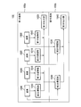
- FIG. 4 shows a configuration of an imaging device 11 which is a modified example of the imaging device 10.
- the imaging device 11 includes an imaging unit 100, a first change amount calculation unit 110, a second change amount calculation unit 120, a control unit 130, an image processing unit 140, and an image recording unit.
- a unit 150 and an image display unit 160 are provided.
- the imaging device 11 is configured in the same manner as a general camera such as a digital camera.
- the image processing unit 140 performs image processing on the image output from the imaging unit 100.
- the image recording unit 150 records the image processed by the image processing unit 140.
- the image display unit 160 displays the image processed by the image processing unit 140.
- the influence of subjects other than important subjects on control of the resolution of the imaging unit 100 can be reduced.
- FIG. 5 shows the configuration of a capsule endoscope 20 to which the imaging device 10 is applied.
- the capsule endoscope 20 includes an imaging unit 100, a first change amount calculation unit 110, a second change amount calculation unit 120, a control unit 130, and an image processing unit 140.
- a wireless communication unit 170 that is, in the present modification, the capsule endoscope 20 includes the imaging device 10, the image processing unit 140, and the wireless communication unit 170.
- the wireless communication unit 170 wirelessly transmits the image processed by the image processing unit 140 to the receiving device.
- the present embodiment is more effective when the capsule endoscope 20 moves and approaches or moves away from the lesion.
- the capsule endoscope 20 moves and approaches or moves away from the lesion.
- Inside the living body there are a change in the information amount of the image due to appearance and disappearance of an important subject (lesion) and a change in the information amount of the image due to the imaging environment (background).
- the amount of information in an image according to the shooting environment (background) keeps changing a little.
- the influence of subjects other than important subjects on control of the resolution of the imaging unit 100 can be reduced.
- the control unit 130 is in one of three states: the low resolution setting state, the medium resolution setting state, and the high resolution setting state.
- the control unit 130 controls the resolution of the imaging unit 100 based on the result of comparing the amount of information of the image with the first threshold and the result of comparing the second amount of change with the second threshold.
- the control unit 130 can set any one of three resolutions of high resolution, medium resolution, and low resolution in the imaging unit 100.
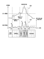
- FIG. 6 shows the processing result of the imaging device 11.
- a graph 600 indicating the amount of information of the image and a graph 610 indicating the absolute value of the second amount of change are shown.
- the horizontal axes of the two graphs in FIG. 6 indicate time.
- the vertical axis of the graph 600 in FIG. 6 indicates the absolute value of the amount of information.
- the vertical axis of the graph 610 in FIG. 6 indicates the absolute value of the second variation.
- FIG. 6 shows a processing result in the case where an important subject and a plurality of subjects similar to the subject and having different degrees of similarity are imaged.
- FIG. 7 shows the contents of control performed by the control unit 130.
- the contents of control according to the result of comparing the information amount with the first threshold and the result of comparing the absolute value of the second change amount with the second threshold are defined.
- the first threshold and the second threshold do not necessarily match.
- control unit 130 performs one of the eight types of processing (1) to (8) according to the comparison result. Below, each process is demonstrated.
- the control unit 130 does not cause the image recording unit 150 to record an image.
- control unit 130 sets the resolution of the imaging unit 100 to a low resolution and causes the image recording unit 150 to record an image.
- the control unit 130 sets the resolution of the imaging unit 100 to a low resolution and causes the image recording unit 150 to record an image.
- the image recording unit 150 records an image while maintaining the resolution set in the imaging unit 100.
- the control unit 130 sets the resolution of the imaging unit 100 to a medium resolution, and causes the image recording unit 150 to record an image.
- control unit 130 sets the resolution of the imaging unit 100 to a high resolution and causes the image recording unit 150 to record an image.
- the control unit 130 sets the resolution of the imaging unit 100 to a resolution higher than the current resolution, and causes the image recording unit 150 to record an image. If the sign of the second change amount is negative, the possibility that the subject included in the image is an important subject is greatly reduced. Therefore, the control unit 130 sets the resolution of the imaging unit 100 to a resolution lower than the current resolution, and causes the image recording unit 150 to record an image.
- the resolution of the imaging unit 100 is not changed regardless of the comparison result.
- the control unit 130 sets the resolution of the imaging unit 100 to an arbitrary resolution. For example, the control unit 130 sets the resolution of the imaging unit 100 to a low resolution. At this time, the information amount of the image is less than the first threshold, and the absolute value of the second change amount is less than the second threshold. Therefore, the control unit 130 does not cause the image recording unit 150 to record an image, as the process (1) in FIG. 7 shows. Thereafter, since the comparison result does not change, the state in which the image is not recorded continues.
- the control unit 130 sets the resolution of the imaging unit 100 to a low resolution and causes the image recording unit 150 to record an image as shown in the process (3) of FIG. 7. After that, although the absolute value of the second change amount becomes smaller than the second threshold, the resolution of the imaging unit 100 is not changed.
- the control unit 130 sets the resolution of the imaging unit 100 to an intermediate resolution and causes the image recording unit 150 to record an image, as shown in the process (6) of FIG. 7. After that, since the comparison result does not change, the resolution of the imaging unit 100 is maintained at the medium resolution.
- the control unit 130 increases the resolution of the imaging unit 100 and causes the image recording unit 150 to record an image, as shown in the process (8) of FIG. 7. That is, the control unit 130 sets the resolution of the imaging unit 100 to a high resolution. After that, although the absolute value of the second change amount becomes smaller than the second threshold, the resolution of the imaging unit 100 is not changed.
- the control unit 130 reduces the resolution of the imaging unit 100 and causes the image recording unit 150 to record an image, as shown in the process (8) in FIG. 7. That is, the control unit 130 sets the resolution of the imaging unit 100 to the medium resolution. After that, although the absolute value of the second change amount becomes smaller than the second threshold, the resolution of the imaging unit 100 is not changed.
- the control unit 130 sets the resolution of the imaging unit 100 to a low resolution, as indicated by the process (2) in FIG. 7. After that, since the comparison result does not change, the resolution of the imaging unit 100 is maintained at a low resolution.
- the influence of subjects other than important subjects on control of the resolution of the imaging unit 100 can be reduced.
- the imaging unit 100 is controlled by controlling the resolution of the imaging unit 100 based on the result of comparing the amount of information of the image with the first threshold and the result of comparing the second variation and the second threshold. You can control the resolution of the image more precisely. Furthermore, by controlling the resolution of the imaging unit 100 based on the code of the second change amount, it is possible to easily determine whether to increase or decrease the resolution of the imaging unit 100.
- the control unit 130 may provide a plurality of first thresholds and a plurality of second thresholds.
- the control unit 130 may control the resolution of the imaging unit 100 based on the result of comparing the amount of information of an image with a plurality of threshold values and the second change amount with a plurality of threshold values. Thereby, the resolution of the imaging unit 100 can be controlled more finely.
- the imaging unit 100 generates a plurality of types of images having different resolutions based on pixel signals having the same exposure timing.
- FIG. 8 shows the configuration of the imaging unit 100.
- the imaging unit 100 includes a first substrate 100 a and a second substrate 100 b.
- the first substrate 100 a and the second substrate 100 b overlap with each other with their main surfaces facing each other. Further, the first substrate 100a and the second substrate 100b are electrically connected.
- the first substrate 100 a includes a plurality of pixels 1000, a plurality of first storage units 1010, and a first output unit 1020.
- the plurality of pixels 1000 include photoelectric conversion elements, and generate a first pixel signal based on incident light.
- the plurality of first accumulation units 1010 accumulate the first pixel signals output from the plurality of pixels 1000.
- the first output unit 1020 outputs images of a plurality of frames formed by the first pixel signals accumulated in the plurality of first accumulation units 1010. Each of the images of a plurality of frames output from the first output unit 1020 is configured by the first pixel signal stored in the plurality of first storage units 1010.
- the second substrate 100 b includes a plurality of second storage units 1030 and a second output unit 1040.
- the plurality of second accumulation units 1030 accumulate second pixel signals obtained by adding the plurality of first pixel signals output from the plurality of pixels 1000 for each plurality. For example, as shown in FIG. 8, the first pixel signals are added every two and stored in the second storage unit 1030.
- the second output unit 1040 outputs images of a plurality of frames formed by the second pixel signals accumulated in the plurality of second accumulation units 1030. Each of the images of the plurality of frames output from the second output unit 1040 is configured of the second pixel signal stored in the plurality of second storage units 1030.
- the number of first pixel signals constituting the image output from the first output unit 1020 is different from the number of second pixel signals constituting the image output from the second output unit 1040. That is, the resolution of the image output from the first output unit 1020 is different from the resolution of the image output from the second output unit 1040. In the example shown in FIG. 8, the resolution of the image output from the second output unit 1040 is half the resolution of the image output from the first output unit 1020.
- the number of first pixel signals to be added may be four or the like.
- the plurality of first storage units 1010, the first output unit 1020, the plurality of second storage units 1030, and the second output unit 1040 have the first substrate regardless of the arrangement of the other configurations. It may be disposed on either of 100a and the second substrate 100b. For example, both the first output unit 1020 and the second output unit 1040 may be disposed on the first substrate 100a or the second substrate 100b.
- the imaging unit 100 may have three or more substrates.
- a plurality of third storage units for accumulating a third pixel signal obtained by adding the plurality of first pixel signals output from the plurality of pixels 1000, and the plurality of third storage units.
- the image processing apparatus may have a third output unit that outputs a plurality of frames of images configured by the third pixel signal accumulated in the accumulation unit.
- the resolution of the image output from the third output unit is different from the resolution of the image output from the first output unit 1020 and the resolution of the image output from the second output unit 1040.
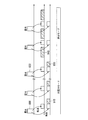
- FIG. 9 shows processing timings of signals in the imaging unit 100.
- the right direction in FIG. 9 is the direction in which time advances.
- the imaging unit 100 operates in one of a normal mode and a low power mode which consumes less power than the normal mode.
- a resolution lower than the resolution set in the imaging unit 100 in the normal mode is set in the imaging unit 100.
- the imaging unit 100 starts operation in the low power mode.
- Exposure of the plurality of pixels 1000 generates a first pixel signal in each of the pixels 1000.
- the first pixel signal generated by the exposure 900 is simultaneously transferred to the first storage unit 1010 and the second storage unit 1030, and the transferred first pixel signal is stored in each storage unit.
- the plurality of first pixel signals are added when transferred to the second accumulation unit 1030.
- a second pixel signal obtained by adding the plurality of first pixel signals is accumulated in the second accumulation unit 1030.
- the second output unit 1040 In the low power mode, the second output unit 1040 outputs an image 910 based on the second pixel signal stored in the second storage unit 1030. While the mode of the imaging unit 100 is the low power mode, the second output unit 1040 repeatedly outputs an image.
- the mode of the imaging unit 100 is changed from the low power mode to the normal mode.
- the first output unit 1020 outputs an image 940 based on the first pixel signal accumulated in the first accumulation unit 1010 immediately after the mode of the imaging unit 100 is changed to the normal mode. While the mode of the imaging unit 100 is the normal mode, the first output unit 1020 repeatedly outputs an image.
- An image 930 output at the end of the operation in the low power mode is an image based on a second pixel signal obtained by adding the first pixel signal generated by the exposure 920. Also, the first output image 940 in the normal mode is an image based on the first pixel signal generated by the exposure 920.
- the first pixel signal is simultaneously transferred from the plurality of pixels 1000 to the first accumulation unit 1010 and the second accumulation unit 1030. Therefore, the first pixel signal stored in the first storage unit 1010 and the first pixel signal that is the source of the second pixel signal stored in the second storage unit 1030 have the same timing. It is a signal generated by exposure.
- the present embodiment it is possible to obtain a plurality of images of different resolutions corresponding to exposure at the same timing with respect to control of the resolution of the imaging unit 100. Therefore, when the resolution of the imaging unit 100 is changed in the imaging device 10 that controls the resolution of the image based on the time change amount of the information change amount of the image, the change is performed without re-exposure with the changed resolution. It is possible to obtain an image of a later resolution. For this reason, it becomes difficult to miss an important subject. In particular, when the resolution of the imaging unit 100 is changed to a higher resolution, it is difficult to miss an important subject at the timing when the resolution is changed, that is, the timing when the movement of the important subject largely changes.
- the first change amount which is the information change amount of the image
- the second change amount which is the time change amount of the first change amount
- imaging device 20 capsule endoscope 100 imaging unit 100a first substrate 100b second substrate 110 first variation calculation unit 120 second variation calculation unit 130 control unit 140 image processing unit 150 image recording unit 160 image display unit 170 wireless communication unit 1000 pixel 1010 first storage unit 1020 first output unit 1030 second storage unit 1040 second output unit
Landscapes
- Health & Medical Sciences (AREA)
- Life Sciences & Earth Sciences (AREA)
- Engineering & Computer Science (AREA)
- Surgery (AREA)
- Physics & Mathematics (AREA)
- Signal Processing (AREA)
- Optics & Photonics (AREA)
- Multimedia (AREA)
- Public Health (AREA)
- Medical Informatics (AREA)
- Biophysics (AREA)
- Nuclear Medicine, Radiotherapy & Molecular Imaging (AREA)
- Pathology (AREA)
- Radiology & Medical Imaging (AREA)
- Veterinary Medicine (AREA)
- Biomedical Technology (AREA)
- Heart & Thoracic Surgery (AREA)
- General Health & Medical Sciences (AREA)
- Molecular Biology (AREA)
- Animal Behavior & Ethology (AREA)
- Computer Networks & Wireless Communication (AREA)
- Astronomy & Astrophysics (AREA)
- General Physics & Mathematics (AREA)
- Human Computer Interaction (AREA)
- Studio Devices (AREA)
- Endoscopes (AREA)
- Transforming Light Signals Into Electric Signals (AREA)
- Instruments For Viewing The Inside Of Hollow Bodies (AREA)
Abstract
この撮像装置は、撮像部と、第1の変化量算出部と、第2の変化量算出部と、制御部と、を有する。撮像部は、連続的に撮像を行い、解像度が複数の解像度のいずれかである複数フレームの画像を生成する。第1の変化量算出部は、複数フレームの画像の情報変化量である第1の変化量を算出する。第2の変化量算出部は、第1の変化量の時間変化量である第2の変化量を算出する。制御部は、第2の変化量と閾値とを比較した結果に基づいて撮像部の解像度を制御する。
Description
本発明は、画像の解像度を変更可能な撮像装置およびカプセル内視鏡に関する。
本願は、2014年6月23日に日本国に出願された特願2014-128040号に基づき優先権を主張し、その内容をここに援用する。
本願は、2014年6月23日に日本国に出願された特願2014-128040号に基づき優先権を主張し、その内容をここに援用する。
撮像時に画像の解像度を自律的に変更することで、記録される画像のデータ量を抑制することが可能な技術が開示されている。例えば、特許文献1に開示された技術では、画像の情報変化量が大きい場合には高い解像度が設定される。また、画像の情報変化量が小さい場合には低い解像度が設定される。
従来技術では、重要な被写体以外の被写体によって、画像の情報変化量が影響を受ける場合がある。例えば、多数の葉が付いた木の枝が背景に存在する場合、風で枝が揺れ、葉が動くことにより、画像の情報変化量が大きくなる可能性がある。この場合、重要な被写体の情報変化量が大きくない場合でも、高い解像度が設定される可能性がある。
本発明は、解像度の制御に対する、重要な被写体以外の被写体の影響を低減することができる撮像装置およびカプセル内視鏡を提供することを目的とする。
本発明の第一の態様によれば、撮像装置は、連続的に撮像を行い、解像度が複数の解像度のいずれかである複数フレームの画像を生成する撮像部と、前記複数フレームの画像の情報変化量である第1の変化量を算出する第1の変化量算出部と、前記第1の変化量の時間変化量である第2の変化量を算出する第2の変化量算出部と、前記第2の変化量と閾値とを比較した結果に基づいて前記撮像部の前記解像度を制御する制御部と、を有する。
本発明の第二の態様によれば、前記第一の態様に係る撮像装置において、前記撮像部は、入射した光に基づく第1の画素信号を生成する複数の画素と、前記複数の画素から出力された前記第1の画素信号を蓄積する複数の第1の蓄積部と、前記複数の第1の蓄積部に蓄積された前記第1の画素信号で構成された前記複数フレームの画像を出力する第1の出力部と、前記複数の画素から出力された前記第1の画素信号を複数個毎に加算した第2の画素信号を蓄積する複数の第2の蓄積部と、前記複数の第2の蓄積部に蓄積された前記第2の画素信号で構成された前記複数フレームの画像を出力する第2の出力部と、を有してもよい。
本発明の第三の態様によれば、前記第一の態様に係る撮像装置において、前記制御部は、前記画像の情報量と第1の閾値とを比較した結果、および前記第2の変化量と第2の閾値とを比較した結果に基づいて前記撮像部の前記解像度を制御してもよい。
本発明の第四の態様によれば、カプセル内視鏡は、前記第一の態様に係る撮像装置を有する。
本発明の撮像装置およびカプセル内視鏡によれば、画像の情報変化量である第1の変化量を算出し、第1の変化量の時間変化量である第2の変化量を算出し、第2の変化量と閾値とを比較した結果に基づいて撮像部の解像度を制御することによって、解像度の制御に対する、重要な被写体以外の被写体の影響を低減することができる。
以下、図面を参照し、本発明の実施形態を説明する。
(第1の実施形態)
まず、本発明の第1の実施形態を説明する。図1は、本実施形態による撮像装置10の構成を示している。図1に示すように、撮像装置10は、撮像部100と、第1の変化量算出部110と、第2の変化量算出部120と、制御部130とを有する。
まず、本発明の第1の実施形態を説明する。図1は、本実施形態による撮像装置10の構成を示している。図1に示すように、撮像装置10は、撮像部100と、第1の変化量算出部110と、第2の変化量算出部120と、制御部130とを有する。
撮像部100は、連続的に撮像を行い、解像度が複数の解像度のいずれかである複数フレームの画像(画像信号)を生成する。撮像部100に対して複数の解像度のいずれかを設定することが可能である。また、撮像部100に設定される解像度を変更することが可能である。
第1の変化量算出部110は、複数フレームの画像の情報変化量である第1の変化量を算出する。例えば、第1の変化量は、異なる時間に撮影された2フレームの画像における画像信号の差分絶対値和である。あるいは、第1の変化量は、異なる時間に撮影された2フレームの画像における画像信号から生成された情報量(特徴量)の差分絶対値和であってもよい。例えば、第1の変化量算出部110は、連続する2フレームの画像の第1の変化量を算出する。第1の変化量算出部110は、k(kは2以上の自然数)フレーム毎にn(nは自然数)フレームの画像とn+kフレームの画像との第1の変化量を算出してもよい。第1の変化量算出部110は、複数フレームの画像を記憶する記憶部を有していてもよい。あるいは、撮像部100から出力された画像を記憶する記憶部が第1の変化量算出部110とは別に設けられていてもよい。
第2の変化量算出部120は、第1の変化量の時間変化量である第2の変化量を算出する。例えば、第2の変化量算出部120は、連続して算出された2個の第1の変化量から第2の変化量を算出する。制御部130が行う処理を容易にするため、第2の変化量は時間変化量の絶対値であってもよい。第2の変化量が絶対値である場合、撮像装置10は第2の変化量の符号(正、負)を第2の変化量と共に保持する。
制御部130は、第2の変化量と閾値とを比較した結果に基づいて撮像部100の解像度を制御する。例えば、第2の変化量が閾値未満である場合、制御部130は、撮像部100の解像度を第1の解像度に設定する。また、第2の変化量が閾値以上である場合、制御部130は、撮像部100の解像度を、第1の解像度よりも高い第2の解像度に設定する。制御部130は、第2の変化量と閾値とを比較した結果と、第2の変化量の符号を判別した結果とに基づいて撮像部100の解像度を制御することが望ましい。
図2A、図2B、図3A、及び図3Bを参照して、撮像部100の解像度を制御する処理を説明する。図2Aは、撮像装置10の処理結果を示している。図2Bは、従来の撮像装置の処理結果を示している。図2Aと図2Bとにおけるグラフの横軸は時間を示している。図2Aにおけるグラフの縦軸は第2の変化量の絶対値を示している。図2Bにおけるグラフの縦軸は画像の情報変化量を示している。図2Aと図2Bとは、重要な被写体のみの情報量が変化する場合の処理結果を示している。例えば、重要な被写体の背景に多数の葉が付いた木の枝が存在し、枝と葉とが動かない場合の処理結果が、図2Aと図2Bとに示す処理結果となる。
図2Aに示す撮像装置10の処理では、制御部130は、低解像度設定状態と高解像度設定状態との2状態のいずれかにあり、第2の変化量の絶対値と閾値とを繰り返し比較する。タイミングT11までの比較では、第2の変化量の絶対値は閾値未満であると判定される。この結果、タイミングT11まで、制御部130は低解像度設定状態にあり、撮像部100の解像度が低解像度に設定される。第2の変化量の絶対値が閾値以上であり、かつ、第2の変化量の符号が正である条件が満たされるまで低解像度設定状態が維持される。
タイミングT11での比較では、第2の変化量の絶対値は閾値以上であり、かつ、第2の変化量の符号が正である。このとき、制御部130は、低解像度設定状態から高解像度設定状態に遷移し、撮像部100の解像度を高解像度に設定する。第2の変化量の絶対値が閾値以上であり、かつ、第2の変化量の符号が負である条件が満たされるまで高解像度設定状態が維持される。
続いて、タイミングT12での比較では、第2の変化量の絶対値は閾値以上であり、かつ、第2の変化量の符号が負である。このとき、制御部130は、高解像度設定状態から低解像度設定状態に遷移し、撮像部100の解像度を低解像度に設定する。タイミングT12の後、第2の変化量の絶対値が閾値以上であり、かつ、第2の変化量の符号が正である条件が満たされるまで低解像度設定状態が維持される。
図2Bに示す従来の撮像装置の処理では、画像の情報変化量と閾値とを比較した結果に基づいて撮像部の解像度が設定される。タイミングT101までの比較では、画像の情報変化量は閾値未満であると判定される。この結果、タイミングT101まで、撮像部の解像度が低解像度に設定される。
タイミングT101の比較では、画像の情報変化量が閾値以上であると判定される。このため、撮像部の解像度が高解像度に設定される。タイミングT101の後、画像の情報変化量が閾値以上である間、撮像部の解像度は変更されない。
続いて、タイミングT102の比較では、画像の情報変化量が閾値未満であると判定される。このため、撮像部の解像度が低解像度に設定される。タイミングT102の後、画像の情報変化量が閾値未満である間、撮像部の解像度は変更されない。
図2Aと図2Bとに示す処理では、重要な被写体のみが画像に含まれるため、解像度はほぼ同様に変化する。
図3Aは、撮像装置10の処理結果を示している。図3Bは、従来の撮像装置の処理結果を示している。図3Aと図3Bとにおけるグラフの横軸は時間を示している。図3Aにおけるグラフの縦軸は第2の変化量の絶対値を示している。図3Bにおけるグラフの縦軸は画像の情報変化量を示している。図3Aと図3Bとは、重要な被写体とそれ以外の被写体との情報量が変化する場合の処理結果を示している。例えば、重要な被写体の背景に多数の葉が付いた木の枝が存在し、風で枝が揺れ、葉が動く場合の処理結果が、図3Aと図3Bとに示す処理結果となる。
図3Aに示す撮像装置10の処理では、撮像部100の解像度は、図2Aに示す処理と同様に変化する。すなわち、タイミングT21まで、第2の変化量は閾値未満であるため、撮像部100の解像度が低解像度に設定される。タイミングT21では、第2の変化量の絶対値は閾値以上であり、かつ、第2の変化量の符号が正であると判定されるため、撮像部100の解像度は高解像度に設定される。タイミングT21の後、タイミングT22まで、撮像部100の解像度は変更されない。タイミングT22では、第2の変化量の絶対値は閾値以上であり、かつ、第2の変化量の符号が負であると判定されるため、撮像部100の解像度は低解像度に設定される。タイミングT22の後、撮像部100の解像度は変更されない。
図3Bに示す従来の撮像装置の処理では、画像の情報変化量と閾値とを比較した結果に基づいて撮像部の解像度が設定される。図3Bに示すように、画像の情報変化量が常に閾値以上である。この結果、撮像部の解像度が常に高解像度に設定される。重要な被写体以外の被写体による情報変化量よりも大きな閾値を設定できるが、その場合は、重要な被写体の情報変化量を見落とす可能性がある。
図3Bでは、重要な被写体以外の被写体による情報変化量が常に閾値以上であるため、重要な被写体による画像の情報変化量に関わらず、撮像部の解像度が高解像度に設定される。つまり、図3Bに示す従来の撮像装置の処理では、重要な被写体以外の被写体の影響により、撮像部の解像度が誤って設定される。一方、図3Aに示す撮像装置10の処理では、第2の変化量から重要な被写体以外の被写体の影響が排除されているので、撮像部100の解像度を適切に設定することができる。
本実施形態によれば、撮像装置10は、連続的に撮像を行い、解像度が複数の解像度のいずれかである複数フレームの画像を生成する撮像部100と、複数フレームの画像の情報変化量である第1の変化量を算出する第1の変化量算出部110と、第1の変化量の時間変化量である第2の変化量を算出する第2の変化量算出部120と、第2の変化量と閾値とを比較した結果に基づいて撮像部100の解像度を制御する制御部130と、を有する。
本実施形態では、画像の情報変化量である第1の変化量を算出し、第1の変化量の時間変化量である第2の変化量を算出し、第2の変化量と閾値とを比較した結果に基づいて撮像部100の解像度を制御することによって、解像度の制御に対する、重要な被写体以外の被写体の影響を低減することができる。さらに、第2の変化量の符号に基づいて撮像部100の解像度を制御することによって、撮像部100の解像度を上げるのか下げるのかを容易に判定することができる。
また、第2の変化量が閾値未満の場合に、撮像部100の解像度を、第1の変化量が閾値以上である場合よりも低い解像度に設定することによって、撮像装置10の消費電力を低減することができる。さらに、記録される画像のデータ量を抑制ことができる。さらに、撮像装置10の処理負荷を抑制することができる。
次に、本実施形態の変形例を説明する。
(第1の変形例)
図4は、撮像装置10の変形例である撮像装置11の構成を示している。図4に示すように、撮像装置11は、撮像部100と、第1の変化量算出部110と、第2の変化量算出部120と、制御部130と、画像処理部140と、画像記録部150と、画像表示部160とを有する。撮像装置11は、デジタルカメラ等の一般的なカメラと同様に構成されている。
図4は、撮像装置10の変形例である撮像装置11の構成を示している。図4に示すように、撮像装置11は、撮像部100と、第1の変化量算出部110と、第2の変化量算出部120と、制御部130と、画像処理部140と、画像記録部150と、画像表示部160とを有する。撮像装置11は、デジタルカメラ等の一般的なカメラと同様に構成されている。
以下では、撮像装置10の構成と異なる構成についてのみ説明する。画像処理部140は、撮像部100から出力された画像に対して、画像処理を行う。画像記録部150は、画像処理部140によって処理された画像を記録する。画像表示部160は、画像処理部140によって処理された画像を表示する。
本変形例では、撮像部100の解像度の制御に対する、重要な被写体以外の被写体の影響を低減することができる。
(第2の変形例)
図5は、撮像装置10を適用したカプセル内視鏡20の構成を示している。図5に示すように、カプセル内視鏡20は、撮像部100と、第1の変化量算出部110と、第2の変化量算出部120と、制御部130と、画像処理部140と、無線通信部170とを有する。つまり、本変形例では、カプセル内視鏡20は、撮像装置10と、画像処理部140と、無線通信部170とを有する。
図5は、撮像装置10を適用したカプセル内視鏡20の構成を示している。図5に示すように、カプセル内視鏡20は、撮像部100と、第1の変化量算出部110と、第2の変化量算出部120と、制御部130と、画像処理部140と、無線通信部170とを有する。つまり、本変形例では、カプセル内視鏡20は、撮像装置10と、画像処理部140と、無線通信部170とを有する。
以下では、撮像装置10,11の構成と異なる構成についてのみ説明する。無線通信部170は、画像処理部140によって処理された画像を無線により受信装置に送信する。
例えば、本実施形態は、カプセル内視鏡20が移動して、病変部に近づく、または病変部から遠ざかる場合に、より効果的である。生体の内部では、重要な被写体(病変部)の出現と消失とによる画像の情報量の変化と、撮影環境(背景)による画像の情報量の変化とがある。撮影環境(背景)による画像の情報量は少なからず変化し続ける。本変形例では、撮像部100の解像度の制御に対する、重要な被写体以外の被写体の影響を低減することができる。
(第3の変形例)
図4に示す撮像装置11を用いて本変形例を説明する。本変形例では、制御部130は、低解像度設定状態と、中解像度設定状態と、高解像度設定状態との3状態のいずれかにある。制御部130は、画像の情報量と第1の閾値とを比較した結果、および第2の変化量と第2の閾値とを比較した結果に基づいて撮像部100の解像度を制御する。制御部130は、高解像度と中解像度と低解像度との3つの解像度のいずれかを撮像部100に設定することが可能である。
図4に示す撮像装置11を用いて本変形例を説明する。本変形例では、制御部130は、低解像度設定状態と、中解像度設定状態と、高解像度設定状態との3状態のいずれかにある。制御部130は、画像の情報量と第1の閾値とを比較した結果、および第2の変化量と第2の閾値とを比較した結果に基づいて撮像部100の解像度を制御する。制御部130は、高解像度と中解像度と低解像度との3つの解像度のいずれかを撮像部100に設定することが可能である。
図6は、撮像装置11の処理結果を示している。図6では、画像の情報量を示すグラフ600と、第2の変化量の絶対値を示すグラフ610とが示されている。図6における2つのグラフの横軸は時間を示している。図6におけるグラフ600の縦軸は情報量の絶対値を示している。図6におけるグラフ610の縦軸は第2の変化量の絶対値を示している。図6は、重要な被写体と、その被写体に類似し、類似度が異なる複数の被写体とが撮像される場合の処理結果を示している。
図7は、制御部130が行う制御の内容を示している。図7では、情報量と第1の閾値とを比較した結果、および第2の変化量の絶対値と第2の閾値とを比較した結果に応じた制御の内容が規定されている。第1の閾値と第2の閾値とは、必ずしも一致しない。
図7に示すように、制御部130は、比較結果に応じて(1)から(8)の8種類の処理のいずれかを行う。以下では、各処理について説明する。
(1)画像の情報量が第1の閾値未満、第2の変化量の絶対値が第2の閾値未満、前回検出された画像の情報量が第1の閾値未満である場合
画像に含まれる被写体が重要な被写体ではなく、シーンの変化がない。このため、制御部130は、画像記録部150に画像を記録させない。
画像に含まれる被写体が重要な被写体ではなく、シーンの変化がない。このため、制御部130は、画像記録部150に画像を記録させない。
(2)画像の情報量が第1の閾値未満、第2の変化量の絶対値が第2の閾値未満、前回検出された画像の情報量が第1の閾値以上である場合
画像に含まれる被写体が重要な被写体である可能性が下がる。このため、制御部130は、撮像部100の解像度を低解像度に設定し、画像記録部150に画像を記録させる。
画像に含まれる被写体が重要な被写体である可能性が下がる。このため、制御部130は、撮像部100の解像度を低解像度に設定し、画像記録部150に画像を記録させる。
(3)画像の情報量が第1の閾値未満、第2の変化量の絶対値が第2の閾値以上、前回検出された画像の情報量が第1の閾値未満である場合
第2の変化量の符号に応じて処理が異なる。第2の変化量の符号が負である場合、画像に含まれる被写体が重要な被写体である可能性が大きく下がる。このため、制御部130は、画像記録部150に画像を記録させない。第2の変化量の符号が正である場合、画像に含まれる被写体が重要な被写体である可能性が大きく上がる。このため、制御部130は、撮像部100の解像度を低解像度に設定し、画像記録部150に画像を記録させる。
第2の変化量の符号に応じて処理が異なる。第2の変化量の符号が負である場合、画像に含まれる被写体が重要な被写体である可能性が大きく下がる。このため、制御部130は、画像記録部150に画像を記録させない。第2の変化量の符号が正である場合、画像に含まれる被写体が重要な被写体である可能性が大きく上がる。このため、制御部130は、撮像部100の解像度を低解像度に設定し、画像記録部150に画像を記録させる。
(4)画像の情報量が第1の閾値未満、第2の変化量の絶対値が第2の閾値以上、前回検出された画像の情報量が第1の閾値以上である場合
画像に含まれる被写体が重要な被写体である可能性は低いが、シーンの変化がある。このため、制御部130は、撮像部100の解像度を低解像度に設定し、画像記録部150に画像を記録させる。
画像に含まれる被写体が重要な被写体である可能性は低いが、シーンの変化がある。このため、制御部130は、撮像部100の解像度を低解像度に設定し、画像記録部150に画像を記録させる。
(5)画像の情報量が第1の閾値以上、第2の変化量の絶対値が第2の閾値未満、前回検出された画像の情報量が第1の閾値未満である場合
制御部130は、撮像部100に設定されている解像度を維持しつつ、画像記録部150に画像を記録させる。
制御部130は、撮像部100に設定されている解像度を維持しつつ、画像記録部150に画像を記録させる。
(6)画像の情報量が第1の閾値以上、第2の変化量の絶対値が第2の閾値未満、前回検出された画像の情報量が第1の閾値以上である場合
画像に含まれる被写体が重要な被写体である可能性があるが、画像にノイズが含まれる可能性がある。このため、制御部130は、撮像部100の解像度を中解像度に設定し、画像記録部150に画像を記録させる。
画像に含まれる被写体が重要な被写体である可能性があるが、画像にノイズが含まれる可能性がある。このため、制御部130は、撮像部100の解像度を中解像度に設定し、画像記録部150に画像を記録させる。
(7)画像の情報量が第1の閾値以上、第2の変化量の絶対値が第2の閾値以上、前回検出された画像の情報量が第1の閾値未満である場合
画像に含まれる被写体が重要な被写体である可能性が大きく上がる。このため、制御部130は、撮像部100の解像度を高解像度に設定し、画像記録部150に画像を記録させる。
画像に含まれる被写体が重要な被写体である可能性が大きく上がる。このため、制御部130は、撮像部100の解像度を高解像度に設定し、画像記録部150に画像を記録させる。
(8)画像の情報量が第1の閾値以上、第2の変化量の絶対値が第2の閾値以上、前回検出された画像の情報量が第1の閾値以上である場合
第2の変化量の符号に応じて処理が異なる。第2の変化量の符号が正である場合、画像に含まれる被写体が重要な被写体である可能性が大きく上がる。このため、制御部130は、撮像部100の解像度を現在の解像度よりも高い解像度に設定し、画像記録部150に画像を記録させる。第2の変化量の符号が負である場合、画像に含まれる被写体が重要な被写体である可能性が大きく下がる。このため、制御部130は、撮像部100の解像度を現在の解像度よりも低い解像度に設定し、画像記録部150に画像を記録させる。
第2の変化量の符号に応じて処理が異なる。第2の変化量の符号が正である場合、画像に含まれる被写体が重要な被写体である可能性が大きく上がる。このため、制御部130は、撮像部100の解像度を現在の解像度よりも高い解像度に設定し、画像記録部150に画像を記録させる。第2の変化量の符号が負である場合、画像に含まれる被写体が重要な被写体である可能性が大きく下がる。このため、制御部130は、撮像部100の解像度を現在の解像度よりも低い解像度に設定し、画像記録部150に画像を記録させる。
第2の変化量の絶対値が第2の閾値以上である状態から第2の閾値未満に変化した場合には、比較結果に関わらず、撮像部100の解像度は変更されない。
画像の情報量が図6に示すグラフ600のように変化し、第2の変化量の絶対値が図6に示すグラフ610のように変化する場合の撮像装置11の動作を説明する。撮像装置11が処理を開始した後、制御部130は撮像部100の解像度を任意の解像度に設定する。例えば、制御部130は撮像部100の解像度を低解像度に設定する。このとき、画像の情報量は第1の閾値未満であり、第2の変化量の絶対値は第2の閾値未満である。このため、制御部130は、図7の(1)の処理が示すように、画像記録部150に画像を記録させない。その後、比較結果が変化しないため、画像が記録されない状態が継続する。
タイミングT31での比較では、画像の情報量は第1の閾値未満であり、第2の変化量の絶対値は第2の閾値以上であり、かつ、前回検出された画像の情報量が第1の閾値未満であると判定される。また、第2の変化量の符号が正であると判定される。このとき、制御部130は、図7の(3)の処理が示すように、撮像部100の解像度を低解像度に設定し、画像記録部150に画像を記録させる。その後、第2の変化量の絶対値が第2の閾値未満となるが、撮像部100の解像度は変更されない。
続いて、画像の情報量が第1の閾値以上であることが検出されたタイミングの次のタイミングT32での比較では、画像の情報量は第1の閾値以上であり、第2の変化量の絶対値は第2の閾値未満であり、かつ、前回検出された画像の情報量が第1の閾値以上であると判定される。このとき、制御部130は、図7の(6)の処理が示すように、撮像部100の解像度を中解像度に設定し、画像記録部150に画像を記録させる。その後、比較結果が変化しないため、撮像部100の解像度は中解像度に維持される。
続いて、タイミングT33での比較では、画像の情報量は第1の閾値以上であり、第2の変化量の絶対値は第2の閾値以上であり、かつ、前回検出された画像の情報量が第1の閾値以上であると判定される。また、第2の変化量の符号が正であると判定される。このとき、制御部130は、図7の(8)の処理が示すように、撮像部100の解像度を上げ、画像記録部150に画像を記録させる。つまり、制御部130は、撮像部100の解像度を高解像度に設定する。その後、第2の変化量の絶対値が第2の閾値未満となるが、撮像部100の解像度は変更されない。
続いて、タイミングT34での比較では、画像の情報量は第1の閾値以上であり、第2の変化量の絶対値は第2の閾値以上であり、かつ、前回検出された画像の情報量が第1の閾値以上であると判定される。また、第2の変化量の符号が負であると判定される。このとき、制御部130は、図7の(8)の処理が示すように、撮像部100の解像度を下げ、画像記録部150に画像を記録させる。つまり、制御部130は、撮像部100の解像度を中解像度に設定する。その後、第2の変化量の絶対値が第2の閾値未満となるが、撮像部100の解像度は変更されない。
続いて、タイミングT35での比較では、画像の情報量は第1の閾値未満であり、第2の変化量の絶対値は第2の閾値未満であり、かつ、前回検出された画像の情報量が第1の閾値以上であると判定される。このとき、制御部130は、図7の(2)の処理が示すように、撮像部100の解像度を低解像度に設定する。その後、比較結果が変化しないため、撮像部100の解像度は低解像度に維持される。
本変形例では、撮像部100の解像度の制御に対する、重要な被写体以外の被写体の影響を低減することができる。また、画像の情報量と第1の閾値とを比較した結果、および第2の変化量と第2の閾値とを比較した結果に基づいて撮像部100の解像度を制御することによって、撮像部100の解像度をより細かく制御することができる。さらに、第2の変化量の符号に基づいて撮像部100の解像度を制御することによって、撮像部100の解像度を上げるのか下げるのかを容易に判定することができる。
制御部130は、第1の閾値と第2の閾値とをそれぞれ複数設けてもよい。制御部130は、画像の情報量と複数の閾値、および第2の変化量と複数の閾値とを比較した結果に基づいて撮像部100の解像度を制御してもよい。これによって、撮像部100の解像度をより細かく制御することができる。
(第2の実施形態)
次に、本発明の第2の実施形態を説明する。図1に示す撮像装置10を用いて本実施形態を説明する。本実施形態では、撮像部100は、露光タイミングが同一の画素信号に基づいて、解像度が異なる複数種類の画像を生成する。
次に、本発明の第2の実施形態を説明する。図1に示す撮像装置10を用いて本実施形態を説明する。本実施形態では、撮像部100は、露光タイミングが同一の画素信号に基づいて、解像度が異なる複数種類の画像を生成する。
図8は、撮像部100の構成を示している。図8に示すように、撮像部100は、第1の基板100aと第2の基板100bとを有する。例えば、第1の基板100aと第2の基板100bとは、互いの主面が向かい合った状態で重なっている。また、第1の基板100aと第2の基板100bとは電気的に接続されている。
第1の基板100aは、複数の画素1000と、複数の第1の蓄積部1010と、第1の出力部1020とを有する。複数の画素1000は、光電変換素子を有しており、入射した光に基づく第1の画素信号を生成する。複数の第1の蓄積部1010は、複数の画素1000から出力された第1の画素信号を蓄積する。第1の出力部1020は、複数の第1の蓄積部1010に蓄積された第1の画素信号で構成された複数フレームの画像を出力する。第1の出力部1020から出力される複数フレームの画像のそれぞれは、複数の第1の蓄積部1010に蓄積された第1の画素信号で構成されている。
第2の基板100bは、複数の第2の蓄積部1030と第2の出力部1040とを有する。複数の第2の蓄積部1030は、複数の画素1000から出力された第1の画素信号を複数個毎に加算した第2の画素信号を蓄積する。例えば、図8に示すように、第1の画素信号が2個毎に加算され、第2の蓄積部1030に蓄積される。第2の出力部1040は、複数の第2の蓄積部1030に蓄積された第2の画素信号で構成された複数フレームの画像を出力する。第2の出力部1040から出力される複数フレームの画像のそれぞれは、複数の第2の蓄積部1030に蓄積された第2の画素信号で構成されている。
第1の出力部1020から出力される画像を構成する第1の画素信号の数と、第2の出力部1040から出力される画像を構成する第2の画素信号の数とは異なる。つまり、第1の出力部1020から出力される画像の解像度と、第2の出力部1040から出力される画像の解像度とは異なる。図8に示す例では、第2の出力部1040から出力される画像の解像度は、第1の出力部1020から出力される画像の解像度の2分の1である。加算される第1の画素信号の数は4個等であってもよい。
複数の第1の蓄積部1010と、第1の出力部1020と、複数の第2の蓄積部1030と、第2の出力部1040とは、他の構成の配置に関わらず、第1の基板100aと第2の基板100bとのどちらに配置されていてもよい。例えば、第1の出力部1020と第2の出力部1040との両方が第1の基板100aまたは第2の基板100bに配置されていてもよい。
また、撮像部100が3枚以上の基板を有していてもよい。例えば、撮像部100がさらに、複数の画素1000から出力された第1の画素信号を複数個毎に加算した第3の画素信号を蓄積する複数の第3の蓄積部と、複数の第3の蓄積部に蓄積された第3の画素信号で構成された複数フレームの画像を出力する第3の出力部とを有していてもよい。第3の出力部から出力される画像の解像度は、第1の出力部1020から出力される画像の解像度、および第2の出力部1040から出力される画像の解像度と異なる。
次に、図9を参照して、撮像部100の動作を説明する。図9は、撮像部100における信号の処理タイミングを示している。図9の右方向が時間の進む方向である。
撮像部100は、通常モードと、通常モードよりも消費電力が少ない低電力モードとのいずれかのモードで動作する。低電力モードでは、通常モードにおいて撮像部100に設定される解像度よりも低い解像度が撮像部100に設定される。図9では、撮像部100は低電力モードで動作を開始する。
複数の画素1000の露光により、それぞれの画素1000において第1の画素信号が生成される。露光900により生成された第1の画素信号は第1の蓄積部1010と第2の蓄積部1030とに同時に転送され、転送された第1の画素信号はそれぞれの蓄積部に蓄積される。複数の第1の画素信号は、第2の蓄積部1030に転送されるとき、加算される。複数の第1の画素信号を加算した第2の画素信号が第2の蓄積部1030に蓄積される。
低電力モードでは、第2の出力部1040は、第2の蓄積部1030に蓄積された第2の画素信号に基づく画像910を出力する。撮像部100のモードが低電力モードである間、第2の出力部1040は画像を繰り返し出力する。
第2の蓄積部1030に蓄積された第2の画像信号に基づく画像930が出力された後、撮像部100のモードが低電力モードから通常モードに変更される。第1の出力部1020は、撮像部100のモードが通常モードとなった直後、第1の蓄積部1010に蓄積された第1の画素信号に基づく画像940を出力する。撮像部100のモードが通常モードである間、第1の出力部1020は画像を繰り返し出力する。
低電力モードにおける動作の最後に出力される画像930は、露光920により生成された第1の画素信号を加算した第2の画素信号に基づく画像である。また、通常モードにおける最初に出力される画像940は、露光920により生成された第1の画素信号に基づく画像である。
本実施形態では、複数の画素1000から第1の蓄積部1010と第2の蓄積部1030とに第1の画素信号が同時に転送される。このため、第1の蓄積部1010に蓄積される第1の画素信号と、第2の蓄積部1030に蓄積される第2の画素信号の元となる第1の画素信号とは、同一タイミングの露光により生成された信号である。
本実施形態では、撮像部100の解像度の制御に対する、同一タイミングの露光に対応する、解像度の異なる複数の画像を得ることができる。このため、画像の情報変化量の時間変化量に基づいて画像の解像度を制御する撮像装置10において、撮像部100の解像度が変更される場合に、変更後の解像度で再露光することなく、変更後の解像度の画像を得ることができる。このため、重要な被写体を撮り逃しにくくなる。特に、撮像部100の解像度がより高い解像度に変更される場合に、解像度が変更されたタイミング、すなわち重要な被写体の動きが大きく変化したタイミングにおける重要な被写体を撮り逃しにくくなる。
以上、図面を参照して本発明の実施形態について詳述してきたが、具体的な構成は上記の実施形態に限られるものではなく、本発明の要旨を逸脱しない範囲の設計変更等も含まれる。本発明は前述した説明によって限定されることはなく、添付の請求の範囲によってのみ限定される。
本発明によれば、画像の情報変化量である第1の変化量を算出し、第1の変化量の時間変化量である第2の変化量を算出し、第2の変化量と閾値とを比較した結果に基づいて撮像部の解像度を制御することによって、解像度の制御に対する、重要な被写体以外の被写体の影響を低減することができる撮像装置およびカプセル内視鏡を提供することができる。
10,11 撮像装置
20 カプセル内視鏡
100 撮像部
100a 第1の基板
100b 第2の基板
110 第1の変化量算出部
120 第2の変化量算出部
130 制御部
140 画像処理部
150 画像記録部
160 画像表示部
170 無線通信部
1000 画素
1010 第1の蓄積部
1020 第1の出力部
1030 第2の蓄積部
1040 第2の出力部
20 カプセル内視鏡
100 撮像部
100a 第1の基板
100b 第2の基板
110 第1の変化量算出部
120 第2の変化量算出部
130 制御部
140 画像処理部
150 画像記録部
160 画像表示部
170 無線通信部
1000 画素
1010 第1の蓄積部
1020 第1の出力部
1030 第2の蓄積部
1040 第2の出力部
Claims (4)
- 連続的に撮像を行い、解像度が複数の解像度のいずれかである複数フレームの画像を生成する撮像部と、
前記複数フレームの画像の情報変化量である第1の変化量を算出する第1の変化量算出部と、
前記第1の変化量の時間変化量である第2の変化量を算出する第2の変化量算出部と、
前記第2の変化量と閾値とを比較した結果に基づいて前記撮像部の前記解像度を制御する制御部と、
を有する撮像装置。 - 前記撮像部は、
入射した光に基づく第1の画素信号を生成する複数の画素と、
前記複数の画素から出力された前記第1の画素信号を蓄積する複数の第1の蓄積部と、
前記複数の第1の蓄積部に蓄積された前記第1の画素信号で構成された前記複数フレームの画像を出力する第1の出力部と、
前記複数の画素から出力された前記第1の画素信号を複数個毎に加算した第2の画素信号を蓄積する複数の第2の蓄積部と、
前記複数の第2の蓄積部に蓄積された前記第2の画素信号で構成された前記複数フレームの画像を出力する第2の出力部と、
を有する請求項1に記載の撮像装置。 - 前記制御部は、前記画像の情報量と第1の閾値とを比較した結果、および前記第2の変化量と第2の閾値とを比較した結果に基づいて前記撮像部の前記解像度を制御する請求項1に記載の撮像装置。
- 請求項1に記載の撮像装置を有するカプセル内視鏡。
Priority Applications (1)
| Application Number | Priority Date | Filing Date | Title |
|---|---|---|---|
| US15/359,885 US10334155B2 (en) | 2014-06-23 | 2016-11-23 | Imaging device and capsule endoscope |
Applications Claiming Priority (2)
| Application Number | Priority Date | Filing Date | Title |
|---|---|---|---|
| JP2014128040A JP6334288B2 (ja) | 2014-06-23 | 2014-06-23 | 撮像装置およびカプセル内視鏡 |
| JP2014-128040 | 2014-06-23 |
Related Child Applications (1)
| Application Number | Title | Priority Date | Filing Date |
|---|---|---|---|
| US15/359,885 Continuation US10334155B2 (en) | 2014-06-23 | 2016-11-23 | Imaging device and capsule endoscope |
Publications (1)
| Publication Number | Publication Date |
|---|---|
| WO2015198728A1 true WO2015198728A1 (ja) | 2015-12-30 |
Family
ID=54937826
Family Applications (1)
| Application Number | Title | Priority Date | Filing Date |
|---|---|---|---|
| PCT/JP2015/063581 Ceased WO2015198728A1 (ja) | 2014-06-23 | 2015-05-12 | 撮像装置およびカプセル内視鏡 |
Country Status (3)
| Country | Link |
|---|---|
| US (1) | US10334155B2 (ja) |
| JP (1) | JP6334288B2 (ja) |
| WO (1) | WO2015198728A1 (ja) |
Families Citing this family (1)
| Publication number | Priority date | Publication date | Assignee | Title |
|---|---|---|---|---|
| US11553829B2 (en) | 2017-05-25 | 2023-01-17 | Nec Corporation | Information processing apparatus, control method and program |
Citations (4)
| Publication number | Priority date | Publication date | Assignee | Title |
|---|---|---|---|---|
| JPH08138058A (ja) * | 1994-11-15 | 1996-05-31 | Kobe Steel Ltd | 動画像データ解析方法 |
| JP2003134386A (ja) * | 2001-10-23 | 2003-05-09 | Fuji Photo Film Co Ltd | 撮像装置および撮像方法 |
| JP2013128847A (ja) * | 2011-01-28 | 2013-07-04 | Olympus Medical Systems Corp | カプセル内視鏡システム |
| JP2013175824A (ja) * | 2012-02-23 | 2013-09-05 | Nikon Corp | 電子カメラ |
Family Cites Families (3)
| Publication number | Priority date | Publication date | Assignee | Title |
|---|---|---|---|---|
| US6985172B1 (en) * | 1995-12-01 | 2006-01-10 | Southwest Research Institute | Model-based incident detection system with motion classification |
| US7940973B2 (en) * | 2006-09-19 | 2011-05-10 | Capso Vision Inc. | Capture control for in vivo camera |
| JP5495711B2 (ja) * | 2009-10-26 | 2014-05-21 | キヤノン株式会社 | 撮像装置及び撮像システム、それらの制御方法及びそのプログラム |
-
2014
- 2014-06-23 JP JP2014128040A patent/JP6334288B2/ja active Active
-
2015
- 2015-05-12 WO PCT/JP2015/063581 patent/WO2015198728A1/ja not_active Ceased
-
2016
- 2016-11-23 US US15/359,885 patent/US10334155B2/en active Active
Patent Citations (4)
| Publication number | Priority date | Publication date | Assignee | Title |
|---|---|---|---|---|
| JPH08138058A (ja) * | 1994-11-15 | 1996-05-31 | Kobe Steel Ltd | 動画像データ解析方法 |
| JP2003134386A (ja) * | 2001-10-23 | 2003-05-09 | Fuji Photo Film Co Ltd | 撮像装置および撮像方法 |
| JP2013128847A (ja) * | 2011-01-28 | 2013-07-04 | Olympus Medical Systems Corp | カプセル内視鏡システム |
| JP2013175824A (ja) * | 2012-02-23 | 2013-09-05 | Nikon Corp | 電子カメラ |
Also Published As
| Publication number | Publication date |
|---|---|
| JP2016009906A (ja) | 2016-01-18 |
| JP6334288B2 (ja) | 2018-05-30 |
| US20170078563A1 (en) | 2017-03-16 |
| US10334155B2 (en) | 2019-06-25 |
Similar Documents
| Publication | Publication Date | Title |
|---|---|---|
| US11317045B2 (en) | Event-based image sensor and operating method thereof | |
| JP6320571B2 (ja) | 画像処理装置、画像処理方法およびプログラム | |
| JP6291417B2 (ja) | 撮像装置、集積回路およびフリッカ低減方法 | |
| IL301734A (en) | A system and method for blurring the background in an image using the movement of the camera or the movement of the object | |
| JP6366739B2 (ja) | 画像処理装置、画像処理方法およびプログラム | |
| US20230368333A1 (en) | Methods and apparatus for motion transfer between different media | |
| US10462367B2 (en) | Image capture having temporal resolution and perceived image sharpness | |
| US9270881B2 (en) | Image processing device, image processing method and recording medium capable of generating a wide-range image | |
| WO2016006430A1 (ja) | 撮像装置、撮像方法、およびプログラム、並びに再生装置 | |
| US9300869B2 (en) | Reduction of spatial resolution for temporal resolution | |
| JP6334288B2 (ja) | 撮像装置およびカプセル内視鏡 | |
| JP2019114956A (ja) | 画像処理装置、撮像システム、移動体 | |
| US9813626B2 (en) | Image sensor, operating method therefor, and electronic device | |
| Posch et al. | Live demonstration: Asynchronous time-based image sensor (ATIS) camera with full-custom AE processor | |
| CN116416546B (zh) | 图像处理方法、装置、存储介质及程序产品 | |
| JP2010147950A (ja) | 画像処理装置および画像処理方法、ならびに、撮像装置 | |
| WO2023085138A1 (ja) | 固体撮像装置およびその駆動方法、並びに電子機器 | |
| KR101451133B1 (ko) | 모션 트래킹을 위한 영상 처리 방법 및 장치 | |
| TW202539263A (zh) | 具有視訊圖框插值之混合式影像感測器 | |
| JP2018148260A (ja) | 画像処理装置、画像処理装置の制御方法、及び、プログラム | |
| WO2021152437A1 (en) | System and method for capturing and analysing images and/or videos in low light condition | |
| US9854177B2 (en) | Imaging apparatus | |
| KR20120011241A (ko) | 영상 처리 장치 | |
| Patil et al. | Super Resolution methods to achieve high quality imaging |
Legal Events
| Date | Code | Title | Description |
|---|---|---|---|
| 121 | Ep: the epo has been informed by wipo that ep was designated in this application |
Ref document number: 15810853 Country of ref document: EP Kind code of ref document: A1 |
|
| NENP | Non-entry into the national phase |
Ref country code: DE |
|
| 122 | Ep: pct application non-entry in european phase |
Ref document number: 15810853 Country of ref document: EP Kind code of ref document: A1 |