WO2015198721A1 - 質量分析装置 - Google Patents
質量分析装置 Download PDFInfo
- Publication number
- WO2015198721A1 WO2015198721A1 PCT/JP2015/063411 JP2015063411W WO2015198721A1 WO 2015198721 A1 WO2015198721 A1 WO 2015198721A1 JP 2015063411 W JP2015063411 W JP 2015063411W WO 2015198721 A1 WO2015198721 A1 WO 2015198721A1
- Authority
- WO
- WIPO (PCT)
- Prior art keywords
- rod
- mass spectrometer
- mass
- electrode
- shaped electrode
- Prior art date
- Legal status (The legal status is an assumption and is not a legal conclusion. Google has not performed a legal analysis and makes no representation as to the accuracy of the status listed.)
- Ceased
Links
Images






Classifications
-
- H—ELECTRICITY
- H01—ELECTRIC ELEMENTS
- H01J—ELECTRIC DISCHARGE TUBES OR DISCHARGE LAMPS
- H01J49/00—Particle spectrometers or separator tubes
- H01J49/02—Details
- H01J49/06—Electron- or ion-optical arrangements
- H01J49/062—Ion guides
- H01J49/063—Multipole ion guides, e.g. quadrupoles, hexapoles
-
- H—ELECTRICITY
- H01—ELECTRIC ELEMENTS
- H01J—ELECTRIC DISCHARGE TUBES OR DISCHARGE LAMPS
- H01J49/00—Particle spectrometers or separator tubes
- H01J49/02—Details
- H01J49/06—Electron- or ion-optical arrangements
- H01J49/062—Ion guides
- H01J49/065—Ion guides having stacked electrodes, e.g. ring stack, plate stack
-
- H—ELECTRICITY
- H01—ELECTRIC ELEMENTS
- H01J—ELECTRIC DISCHARGE TUBES OR DISCHARGE LAMPS
- H01J49/00—Particle spectrometers or separator tubes
- H01J49/02—Details
- H01J49/10—Ion sources; Ion guns
-
- H—ELECTRICITY
- H01—ELECTRIC ELEMENTS
- H01J—ELECTRIC DISCHARGE TUBES OR DISCHARGE LAMPS
- H01J49/00—Particle spectrometers or separator tubes
- H01J49/26—Mass spectrometers or separator tubes
- H01J49/34—Dynamic spectrometers
- H01J49/42—Stability-of-path spectrometers, e.g. monopole, quadrupole, multipole, farvitrons
-
- H—ELECTRICITY
- H01—ELECTRIC ELEMENTS
- H01J—ELECTRIC DISCHARGE TUBES OR DISCHARGE LAMPS
- H01J49/00—Particle spectrometers or separator tubes
- H01J49/26—Mass spectrometers or separator tubes
- H01J49/34—Dynamic spectrometers
- H01J49/42—Stability-of-path spectrometers, e.g. monopole, quadrupole, multipole, farvitrons
- H01J49/4205—Device types
- H01J49/421—Mass filters, i.e. deviating unwanted ions without trapping
- H01J49/4215—Quadrupole mass filters
-
- H—ELECTRICITY
- H01—ELECTRIC ELEMENTS
- H01J—ELECTRIC DISCHARGE TUBES OR DISCHARGE LAMPS
- H01J49/00—Particle spectrometers or separator tubes
- H01J49/26—Mass spectrometers or separator tubes
- H01J49/34—Dynamic spectrometers
- H01J49/42—Stability-of-path spectrometers, e.g. monopole, quadrupole, multipole, farvitrons
- H01J49/4205—Device types
- H01J49/4255—Device types with particular constructional features
Definitions
- the present invention relates to a mass spectrometer using a quadrupole mass spectrometer, and more particularly to a mass spectrometer that requires high sensitivity, such as in the case of analysis of an in vivo sample.
- a mass spectrometer using a quadrupole mass spectrometer which is composed of at least four rod-shaped electrodes, and a DC voltage U and a high-frequency voltage V q cos ( ⁇ q t + ⁇ 0 ) are applied to the rod-shaped electrodes.
- an ion transport unit (ion guide unit) consisting of at least four rod-like or plate-like electrodes, to which only a high-frequency voltage V i cos ( ⁇ i t + ⁇ 0 ) is applied, is installed. There are many cases.
- the radius of the inscribed circle whose diameter is the shortest distance between the counter electrodes among the electrodes of the ion transport part is r i
- the shortest distance between the counter electrodes is the diameter among the electrodes of the mass analysis part.
- the radius of the inscribed circle between the rod-shaped electrodes at the position where the ions enter the ion transport portion with respect to the electrode of the ion transport portion is denoted by r i1 , at the position for emitting the ion transport unit, if a radius of an inscribed circle between the rod electrode was r i2, r i1> as the relationship r i2 holds, it described that the ion transport unit electrode is arranged Has been.
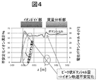
- a peak potential potential barrier is formed as a potential potential distribution at the entrance of the ion guide portion and the entrance of the mass analysis portion, the electric field is distorted, and the ion trajectory is unstable. As a result, ion loss occurred.
- the cause of the ion loss is considered to be that a peak-like potential barrier is generated in the potential potential distribution as shown in FIG. In order to solve the above problems, it is necessary to reduce the distortion of the electric field generated by the peak potential potential barrier generated at the entrance of the ion transport (ion guide) section and the entrance of the mass analysis section.
- the mass spectrometer of the present invention applies to the first rod-shaped electrode, a mass spectrometer including at least four first rod-shaped electrodes that allow passage of only ion species having a specific mass-to-charge ratio m / z.
- a control unit that controls and adjusts the voltage; and a detection unit that detects ions that have passed through the first rod-shaped electrode, and the size of the inscribed circle at at least one end of the first rod-shaped electrode is , Larger than the size of the inscribed circle of the other part of the first rod-like electrode.
- the entrance of the ion transport section and the vicinity of the entrance of the mass spectrometer section Is a device that improves the number of ions (detection sensitivity) detected by reducing the potential distribution (peak distribution) that rapidly increases or decreases with respect to the potential distribution generated in the first step.
- the radius of the inscribed circle of the plurality of rod-shaped electrodes of the ion transport section (ion guide) is ri
- the radius of the inscribed circle of the plurality of rod-shaped electrodes of the mass analyzing section (quadrupole mass analyzing section) is rq
- the ion guide and the electrode of the quadrupole mass spectrometer are arranged so that the relationship of ri> rq is established.
- the inscribed circle diameter gradually increases in the shape of the electrode near the entrance where ions are incident, in the direction opposite to the direction of ion incidence. It has an inclined (tapered) shape that spreads out.
- a sudden increase / decrease (peak) distribution of potential potential generated near the entrance of the mass spectrometer that is, electric field distortion generated at the end of the electrode is reduced.
- the ion transmissivity is greatly improved, and highly sensitive mass spectrometry becomes possible.
- positioning and structure of the ion transport part of this invention, and a mass spectrometry part It is the schematic of the whole mass spectrometer which measures the mass spectrometry data by this invention. It is an ion stable transmission region figure in a quadrupole electric field. It is the figure which put together the result derived
- FIG. It is a conceptual diagram showing the electrode shape of another form with respect to the electrode entrance shape of a mass spectrometer part in the 1st Example of this invention. It is a conceptual diagram showing the entrance end part shape of each electrode of the ion transport part by the 2nd Example of this invention. It is a conceptual diagram showing the edge part shape of the entrance and exit of each electrode of an ion transport part by the 2nd Example of this invention.
- FIG. 1 is a diagram showing an ion transporting part (ion guide) and a mass analyzing part (quadrupole mass analyzing part), which are features of the first embodiment
- FIG. 2 is an overall view of the mass spectrometer of the present embodiment. It is a block diagram. First, an analysis flow of the mass spectrometer 11 is shown.
- Samples to be subjected to mass spectrometry are samples separated and fractionated in time in a pretreatment system 1 such as gas chromatography (GC) or liquid chromatography (LC), and then ionized in the ionization unit 2 one after another.
- the ions pass through the ion transport unit 3 and enter the mass analysis unit 4 to be mass separated.
- m is the ion mass
- z is the charge valence of the ion.
- the voltage to the mass analyzer 4 is applied from the DC voltage source 9 while being controlled by the controller 8.
- the separated ions are detected by the ion detection unit 5, the data processing unit 6 organizes and processes the data, and the mass analysis data as the analysis result is displayed on the display unit 7.
- the ion transport unit 3 and the mass analysis unit 4 are quadrupole mass spectrometers composed of four rod-shaped electrodes, but may be multipole mass spectrometers composed of four or more rod-shaped electrodes.
- the four rod-shaped electrodes are cylindrical as shown in the x, y sectional view of the rod-shaped electrode. It may be an electrode, or may be a rod-like electrode having a bipolar surface shape as indicated by a dotted line.
- the four electrodes in the mass spectrometer 4 are a pair of electrodes facing each other, and the two sets of electrodes 13a and 13b have a voltage in the opposite phase of the voltage obtained by superimposing the DC voltage and the high-frequency voltage, + (U + Vcos ⁇ t) , ⁇ (U + Vcos ⁇ t) is applied, and high-frequency electric fields Ex and Ey shown in the equation (1) are generated between the four rod-shaped electrodes.
- the ionized sample ions are introduced along the central axis (z direction) between the rod-shaped electrodes, and pass through the high-frequency electric field of formula (1).
- the stability of the ion trajectory in the x and y directions at this time is determined by the following dimensionless parameters a and q derived from the equation of motion of ions between the rod-shaped electrodes (Mathieu equation).
- valence z 1.
- r 0 is a half value of the distance between the rod electrodes facing each other
- e is an elementary charge
- m is an ion mass
- U is a DC voltage applied to the rod electrode
- V and ⁇ are an amplitude and an angular frequency of the high-frequency voltage.
- Fig. 3 shows the quantitative range (stable transmission region) of a and q that gives a stable solution for ion trajectories in both the X and y directions.
- the vicinity of the top of the stable transmission region in FIG. It is necessary to adjust the U and V ratio so that they intersect (Figure 3).
- the destabilized ions While stably transmitting ions pass between the rod-like electrodes in the z direction while vibrating, the destabilized ions radiate the vibrations and exit in the x and y directions.
- the straight line in equation (4) is called a mass scanning line, and the U and V values are sequentially scanned while maintaining the slope (U / V ratio) of the mass scanning line.
- the mass number M of the ion species to be separated is scanned.
- the mass number M of the ion species is usually increased by increasing the U and V values in proportion to the ion mass m. Are scanned.
- the four electrodes are set as one set facing each other, and the two sets of electrodes 14a and 14b are respectively voltages of only high-frequency voltages of opposite phases, Is applied, and high-frequency electric fields Ex and Ey shown in the equation (7) are generated between the four rod-shaped electrodes.
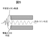
- FIG. 3 shows a conceptual diagram of a state in which a part of ions are destabilized in the vicinity of the electrode entrance of the ion guide part or the mass analysis part.
- the radius r i of the inscribed circle of four or more electrodes of the ion guide portion is the inscribed circle radius r of the four or more rod-shaped electrodes of the mass analyzing portion.
- Each electrode is arranged so as to be larger than q .
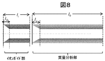
- the shape of the entrance end of each rod-shaped electrode of the mass analysis unit is a tapered shape.
- this tapered shape is characterized by having an inclined (tapered) shape in which the inscribed circle diameter gradually widens in the direction opposite to the direction of ion incidence. .
- the rapid increase / decrease (peak shape) distribution of the potential potential generated near the entrance of the ion guide and the mass analyzer is reduced. It was confirmed by simulation that the ion loss rate in the vicinity was greatly reduced, that is, the ion transmission rate was greatly improved.
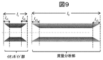
- each electrode shape at the entrance of the mass spectrometer may be an electrode shape that is bent outward so that the entrance side is widened as shown in FIG. 7 instead of the tapered shape. 1 and FIG. 7, the length la of the tapered portion and the length (z-direction length) la of the curved portion maintain the mass separation accuracy. Therefore, if the total length of the electrode is l 0 , l 0/3 or less is desirable.
- the electrode cross-sectional shape of the entrance end is an electrode shape having an inclined shape.
- the rapid increase / decrease (peak shape) distribution of the potential potential is reduced near the entrance of the ion transport part, The destabilization of ion orbit is prevented, and the effect of stable transmission can be expected.
- a taper shape is used, thereby rapidly increasing or decreasing the potential distribution at the exit. The distortion of the electric field is considered to be reduced, and the ion transmission rate is also improved at the exit portion.
- a third embodiment will be described with reference to FIG.
- the amplitude value V i of the RF voltage applied to the electrodes of the ion transport (ion guide) 3 Application is performed so that the following relationship is established between the amplitude value V q of the high-frequency voltage V q cos ( ⁇ q t + ⁇ 0 ) applied to the electrode of the mass spectrometer.
- the inscribed circle radius r i of each electrode of the ion transport section is made larger than the inscribed circle radius r q of each electrode of the mass analysis section.
- the sudden increase and decrease of the potential distribution of the ion transport part is reduced only by adjusting the applied voltage. Is possible.
- the tapered shape or the bent portion at the entrance end of each electrode of the mass spectrometer is movable.
- the taper shape at the entrance end of each electrode, or the angle of the bent portion can be finely adjusted, so that the ion transmittance can be adjusted for each ion species, etc.
- improvement of ion sensitivity can be expected in a wide range (mass range) of the mass-to-charge ratio.
- the proximity distance to the ion transport (ion guide) part can be adjusted, it is considered that the ion loss between the ion transport part and the mass analysis part may be further suppressed.
Landscapes
- Chemical & Material Sciences (AREA)
- Analytical Chemistry (AREA)
- Physics & Mathematics (AREA)
- Engineering & Computer Science (AREA)
- Plasma & Fusion (AREA)
- Other Investigation Or Analysis Of Materials By Electrical Means (AREA)
- Electron Tubes For Measurement (AREA)
Abstract
Description
質量分析部(四重極質量分析部)の入り口でのイオン損失
イオン損失とは、イオン輸送部や質量分析部の内側を通過するはずのイオンの軌道が不安定になり、イオン輸送部や質量分析部の外側に排出されてしまい、最終的に検出されるイオン数(検出感度)が低下してしまうことを言う。このイオン損失の原因は、電位ポテンシャル分布において、図5に示すようにピーク状のポテンシャル障壁が発生し、イオン軌道が不安定化するためと考える。上記の課題を解決するためには、イオン輸送(イオンガイド)部の入り口、質量分析部の入り口に生成される、ピーク状電位ポテンシャル障壁による電界の歪みを軽減する必要が
ある。











2 イオン化部
3 イオン輸送部
4 質量分析部
5 イオン検出部
6 データ処理部
7 表示部
8 制御部
9 DC電圧源
10 ユーザ入力部
11 質量分析装置
12 AC電圧源
13a,b,c,d 電極
14a,b,c,d 電極
Claims (16)
- 特定の質量電荷比m/zを持つイオン種のみを通過させる、少なくとも4本の第1の棒状電極を含む質量分析部と、
前記第1の棒状電極に印加する電圧を調整・制御する制御する制御部と、
第1の棒状電極を通過したイオンを検出する検出部と、を備えた、質量分析装置において、
第1の棒状電極の少なくとも一方の端部における内接円の大きさは、第1の棒状電極の他の部分の内接円の大きさよりも大きく、
第1の棒状電極の少なくとも一方の端部は、互いに対向する部分が切り欠かれた傾斜形状を持つことを特徴とする、質量分析装置。 - 特定の質量電荷比m/zを持つイオン種のみを通過させる、少なくとも4本の第1の棒状電極を含む質量分析部と、
前記第1の棒状電極に印加する電圧を調整・制御する制御する制御部と、
第1の棒状電極を通過したイオンを検出する検出部と、を備えた、質量分析装置において、
第1の棒状電極の少なくとも一方の端部における内接円の大きさは、第1の棒状電極の他の部分の内接円の大きさよりも大きく、
第1の棒状電極の少なくとも一方の端部は、外側に折れ曲がった形状を持つことを特徴とする、質量分析装置。 - 特定の質量電荷比m/zを持つイオン種のみを通過させる、少なくとも4本の第1の棒状電極を含む質量分析部と、
前記第1の棒状電極に印加する電圧を調整・制御する制御する制御部と、
第1の棒状電極を通過したイオンを検出する検出部と、を備えた、質量分析装置において、
第1の棒状電極の少なくとも一方の端部における内接円の大きさは、第1の棒状電極の他の部分の内接円の大きさよりも大きく、
第1の棒状電極の少なくとも一方の端部は、互いに対向する部分が切り欠かれ、丸みを持っていることを特徴とする、質量分析装置。 - 請求項1に記載の質量分析装置において、
第1の棒状電極の少なくとも一方の端部は、可動式であることを特徴とする、質量分析装置。 - 請求項1に記載の質量分析装置において、
第1の棒状電極の両端部における内接円の大きさは、第1の棒状電極の他の部分の内接円の大きさよりも大きいことを特徴とする、質量分析装置。 - 請求項1において、
さらに、イオンを輸送する、イオンガイド部を備えることを特徴とする、質量分析装置。 - 請求項6において、
イオンガイド部は、少なくとも2枚の板状電極を備えることを特徴とする、質量分析装置。 - 請求項6において、
イオンガイド部は、少なくとも4本の第2の棒状電極を備えることを特徴とする、質量分析装置。 - 請求項8において、
イオンガイド部を構成する第2の棒状電極に内接する内接円の大きさの方が、質量分析部を構成する第2の棒状電極に内接する内接円の大きさよりも大きいことを特徴とする、質量分析装置。 - 請求項8において、
イオンガイド部を構成する第2の棒状電極の少なくとも一方の端部における内接円の大きさは、第2の棒状電極の他の部分の内接円の大きさよりも大きいことを特徴とする、質量分析装置。 - 請求項10において、
第2の棒状電極の少なくとも一方の端部は、互いに対向する部分が切り欠かれた傾斜形状を持つことを特徴とする、質量分析装置。 - 請求項10において、
第2の棒状電極の少なくとも一方の端部は、外側に折れ曲がった形状を持つことを特徴とする、質量分析装置。 - 請求項10において、
第2の棒状電極の少なくとも一方の端部は、互いに対向する部分が切り欠かれ、丸みを持っていることを特徴とする、質量分析装置。 - 請求項10において、
第2の棒状電極の少なくとも一方の端部は、可動式であることを特徴とする、質量分析装置。 - 特定の質量電荷比m/zを持つイオン種のみを通過させる、少なくとも4本の第1の棒状電極を含む質量分析部と、
前記第1の棒状電極に印加する電圧を調整・制御する制御する制御部と、
第1の棒状電極を通過したイオンを検出する検出部と、
イオンを輸送する、イオンガイド部と、を備えた、質量分析装置において、
イオンガイド部は、少なくとも4本の第2の棒状電極または少なくとも2枚の板状電極を含んでおり、
イオンガイド部を構成する電極間の最短距離は、質量分析部を構成する電極間の最短距離よりも大きいことを特徴とする、質量分析装置。 - 特定の質量電荷比m/zを持つイオン種のみを通過させる、少なくとも4本の第1の棒状電極を含む質量分析部と、
前記第1の棒状電極に印加する電圧を調整・制御する制御する制御部と、
第1の棒状電極を通過したイオンを検出する検出部と、
イオンを輸送する、イオンガイド部と、を備えた、質量分析装置において、
イオンガイド部は、少なくとも4本の第2の棒状電極または少なくとも2枚の板状電極を含んでおり、
イオンガイド部を構成する電極に印加する高周波電圧の振幅値よりも、質量分析部を構成する電極に高周波電圧の振幅値の方が大きいことを特徴とする、質量分析装置。
Priority Applications (4)
| Application Number | Priority Date | Filing Date | Title |
|---|---|---|---|
| GB1621135.1A GB2541346B (en) | 2014-06-25 | 2015-05-11 | Mass spectrometer |
| JP2016529165A JP6277272B2 (ja) | 2014-06-25 | 2015-05-11 | 質量分析装置 |
| US15/318,858 US10068756B2 (en) | 2014-06-25 | 2015-05-11 | Mass spectrometer |
| DE112015002415.8T DE112015002415B4 (de) | 2014-06-25 | 2015-05-11 | Massenspektrometer |
Applications Claiming Priority (2)
| Application Number | Priority Date | Filing Date | Title |
|---|---|---|---|
| JP2014-129806 | 2014-06-25 | ||
| JP2014129806 | 2014-06-25 |
Publications (1)
| Publication Number | Publication Date |
|---|---|
| WO2015198721A1 true WO2015198721A1 (ja) | 2015-12-30 |
Family
ID=54937820
Family Applications (1)
| Application Number | Title | Priority Date | Filing Date |
|---|---|---|---|
| PCT/JP2015/063411 Ceased WO2015198721A1 (ja) | 2014-06-25 | 2015-05-11 | 質量分析装置 |
Country Status (5)
| Country | Link |
|---|---|
| US (1) | US10068756B2 (ja) |
| JP (1) | JP6277272B2 (ja) |
| DE (1) | DE112015002415B4 (ja) |
| GB (1) | GB2541346B (ja) |
| WO (1) | WO2015198721A1 (ja) |
Cited By (1)
| Publication number | Priority date | Publication date | Assignee | Title |
|---|---|---|---|---|
| WO2018016408A1 (ja) * | 2016-07-21 | 2018-01-25 | 株式会社日立ハイテクノロジーズ | 質量分析装置 |
Families Citing this family (3)
| Publication number | Priority date | Publication date | Assignee | Title |
|---|---|---|---|---|
| US11270877B2 (en) | 2017-07-06 | 2022-03-08 | Dh Technologies Development Pte. Ltd. | Multipole ion guide |
| US11728153B2 (en) * | 2018-12-14 | 2023-08-15 | Thermo Finnigan Llc | Collision cell with enhanced ion beam focusing and transmission |
| US12548751B2 (en) | 2021-05-31 | 2026-02-10 | Shimadzu Corporation | Quadrupole mass spectrometer |
Citations (7)
| Publication number | Priority date | Publication date | Assignee | Title |
|---|---|---|---|---|
| JPH0374042A (ja) * | 1989-08-11 | 1991-03-28 | Jeol Ltd | 四重極質量分析計 |
| JP2002502085A (ja) * | 1998-01-23 | 2002-01-22 | アナリティカ オブ ブランフォード インコーポレーテッド | 多極イオンガイドを用いた質量分光測定法 |
| JP2004014177A (ja) * | 2002-06-04 | 2004-01-15 | Shimadzu Corp | 質量分析装置 |
| WO2009081445A1 (ja) * | 2007-12-20 | 2009-07-02 | Shimadzu Corporation | 質量分析装置 |
| JP2009535761A (ja) * | 2006-04-28 | 2009-10-01 | マイクロマス ユーケー リミテッド | 質量分析計 |
| WO2013057822A1 (ja) * | 2011-10-20 | 2013-04-25 | 株式会社島津製作所 | 質量分析装置 |
| WO2013093077A2 (en) * | 2011-12-21 | 2013-06-27 | Thermo Fisher Scientific (Bremen) Gmbh | Collision cell multipole |
Family Cites Families (10)
| Publication number | Priority date | Publication date | Assignee | Title |
|---|---|---|---|---|
| AU6653296A (en) * | 1995-08-11 | 1997-03-12 | Mds Health Group Limited | Spectrometer with axial field |
| US6753523B1 (en) | 1998-01-23 | 2004-06-22 | Analytica Of Branford, Inc. | Mass spectrometry with multipole ion guides |
| US6417511B1 (en) | 2000-07-17 | 2002-07-09 | Agilent Technologies, Inc. | Ring pole ion guide apparatus, systems and method |
| WO2003102517A2 (en) | 2002-05-30 | 2003-12-11 | Mds Inc., Doing Business As Mds Sciex | Methods and apparatus for reducing artifacts in mass spectrometers |
| CA2626089C (en) * | 2005-11-30 | 2016-10-04 | Mds Analytical Technologies, A Business Unit Of Mds Inc., Doing Business Through Its Sciex Division | Method and apparatus for mass selective axial transport using pulsed axial field |
| GB0608470D0 (en) | 2006-04-28 | 2006-06-07 | Micromass Ltd | Mass spectrometer |
| US7868289B2 (en) * | 2007-04-30 | 2011-01-11 | Ionics Mass Spectrometry Group Inc. | Mass spectrometer ion guide providing axial field, and method |
| US8455814B2 (en) | 2010-05-11 | 2013-06-04 | Agilent Technologies, Inc. | Ion guides and collision cells |
| EP2774170B1 (en) * | 2011-11-03 | 2018-03-14 | Analytik Jena AG | Improvements in or relating to mass spectrometry |
| US9449804B2 (en) * | 2014-11-11 | 2016-09-20 | Agilent Technologies, Inc. | Dual field multipole converging ion guides, hyperbolic ion guides, and related methods |
-
2015
- 2015-05-11 GB GB1621135.1A patent/GB2541346B/en active Active
- 2015-05-11 JP JP2016529165A patent/JP6277272B2/ja active Active
- 2015-05-11 WO PCT/JP2015/063411 patent/WO2015198721A1/ja not_active Ceased
- 2015-05-11 US US15/318,858 patent/US10068756B2/en active Active
- 2015-05-11 DE DE112015002415.8T patent/DE112015002415B4/de active Active
Patent Citations (7)
| Publication number | Priority date | Publication date | Assignee | Title |
|---|---|---|---|---|
| JPH0374042A (ja) * | 1989-08-11 | 1991-03-28 | Jeol Ltd | 四重極質量分析計 |
| JP2002502085A (ja) * | 1998-01-23 | 2002-01-22 | アナリティカ オブ ブランフォード インコーポレーテッド | 多極イオンガイドを用いた質量分光測定法 |
| JP2004014177A (ja) * | 2002-06-04 | 2004-01-15 | Shimadzu Corp | 質量分析装置 |
| JP2009535761A (ja) * | 2006-04-28 | 2009-10-01 | マイクロマス ユーケー リミテッド | 質量分析計 |
| WO2009081445A1 (ja) * | 2007-12-20 | 2009-07-02 | Shimadzu Corporation | 質量分析装置 |
| WO2013057822A1 (ja) * | 2011-10-20 | 2013-04-25 | 株式会社島津製作所 | 質量分析装置 |
| WO2013093077A2 (en) * | 2011-12-21 | 2013-06-27 | Thermo Fisher Scientific (Bremen) Gmbh | Collision cell multipole |
Cited By (1)
| Publication number | Priority date | Publication date | Assignee | Title |
|---|---|---|---|---|
| WO2018016408A1 (ja) * | 2016-07-21 | 2018-01-25 | 株式会社日立ハイテクノロジーズ | 質量分析装置 |
Also Published As
| Publication number | Publication date |
|---|---|
| JP6277272B2 (ja) | 2018-02-07 |
| US20170125230A1 (en) | 2017-05-04 |
| GB201621135D0 (en) | 2017-01-25 |
| GB2541346B (en) | 2022-05-11 |
| DE112015002415T5 (de) | 2017-02-23 |
| GB2541346A (en) | 2017-02-15 |
| US10068756B2 (en) | 2018-09-04 |
| JPWO2015198721A1 (ja) | 2017-04-20 |
| DE112015002415B4 (de) | 2020-01-02 |
Similar Documents
| Publication | Publication Date | Title |
|---|---|---|
| US20140374589A1 (en) | Method and apparatus for improved sensitivity in a mass spectrometer | |
| JP6277272B2 (ja) | 質量分析装置 | |
| JP2017152368A (ja) | 四重極型質量分析計 | |
| WO2018193637A1 (en) | Ion guide device with dc field and associated methods | |
| CN108369890B (zh) | 质量分析装置 | |
| US11276544B2 (en) | Dynamic electron impact ion source | |
| JP6022383B2 (ja) | 質量分析システム、及び方法 | |
| JP5780355B2 (ja) | 質量分析装置 | |
| JP7428282B2 (ja) | サイクロイド質量分析装置及びその分解能の調節方法 | |
| US10707066B2 (en) | Quadrupole mass filter and quadrupole mass spectrometrometer | |
| JP6711407B2 (ja) | イオンガイド及び質量分析装置 | |
| WO2016174990A1 (ja) | 質量分析装置 | |
| US20240038521A1 (en) | Axially progressive lens for transporting charged particles | |
| US11087968B2 (en) | Traveling wave multipole | |
| WO2016114151A1 (ja) | 質量分析装置 | |
| JP6735620B2 (ja) | 質量分析装置 |
Legal Events
| Date | Code | Title | Description |
|---|---|---|---|
| 121 | Ep: the epo has been informed by wipo that ep was designated in this application |
Ref document number: 15812506 Country of ref document: EP Kind code of ref document: A1 |
|
| ENP | Entry into the national phase |
Ref document number: 2016529165 Country of ref document: JP Kind code of ref document: A |
|
| ENP | Entry into the national phase |
Ref document number: 201621135 Country of ref document: GB Kind code of ref document: A Free format text: PCT FILING DATE = 20150511 |
|
| WWE | Wipo information: entry into national phase |
Ref document number: 15318858 Country of ref document: US |
|
| WWE | Wipo information: entry into national phase |
Ref document number: 112015002415 Country of ref document: DE |
|
| 122 | Ep: pct application non-entry in european phase |
Ref document number: 15812506 Country of ref document: EP Kind code of ref document: A1 |