WO2015194441A1 - 二次電池の短絡試験装置 - Google Patents
二次電池の短絡試験装置 Download PDFInfo
- Publication number
- WO2015194441A1 WO2015194441A1 PCT/JP2015/066786 JP2015066786W WO2015194441A1 WO 2015194441 A1 WO2015194441 A1 WO 2015194441A1 JP 2015066786 W JP2015066786 W JP 2015066786W WO 2015194441 A1 WO2015194441 A1 WO 2015194441A1
- Authority
- WO
- WIPO (PCT)
- Prior art keywords
- secondary battery
- short circuit
- circuit test
- rod
- test apparatus
- Prior art date
- Legal status (The legal status is an assumption and is not a legal conclusion. Google has not performed a legal analysis and makes no representation as to the accuracy of the status listed.)
- Ceased
Links
Images








Classifications
-
- G—PHYSICS
- G01—MEASURING; TESTING
- G01R—MEASURING ELECTRIC VARIABLES; MEASURING MAGNETIC VARIABLES
- G01R31/00—Arrangements for testing electric properties; Arrangements for locating electric faults; Arrangements for electrical testing characterised by what is being tested not provided for elsewhere
- G01R31/36—Arrangements for testing, measuring or monitoring the electrical condition of accumulators or electric batteries, e.g. capacity or state of charge [SoC]
-
- H—ELECTRICITY
- H01—ELECTRIC ELEMENTS
- H01M—PROCESSES OR MEANS, e.g. BATTERIES, FOR THE DIRECT CONVERSION OF CHEMICAL ENERGY INTO ELECTRICAL ENERGY
- H01M10/00—Secondary cells; Manufacture thereof
- H01M10/42—Methods or arrangements for servicing or maintenance of secondary cells or secondary half-cells
- H01M10/48—Accumulators combined with arrangements for measuring, testing or indicating the condition of cells, e.g. the level or density of the electrolyte
-
- H—ELECTRICITY
- H02—GENERATION; CONVERSION OR DISTRIBUTION OF ELECTRIC POWER
- H02J—ELECTRIC POWER NETWORKS; CIRCUIT ARRANGEMENTS OR SYSTEMS FOR SUPPLYING OR DISTRIBUTING ELECTRIC POWER; SYSTEMS FOR STORING ELECTRIC ENERGY
- H02J7/00—Circuit arrangements for charging or discharging batteries or for supplying loads from batteries
-
- Y—GENERAL TAGGING OF NEW TECHNOLOGICAL DEVELOPMENTS; GENERAL TAGGING OF CROSS-SECTIONAL TECHNOLOGIES SPANNING OVER SEVERAL SECTIONS OF THE IPC; TECHNICAL SUBJECTS COVERED BY FORMER USPC CROSS-REFERENCE ART COLLECTIONS [XRACs] AND DIGESTS
- Y02—TECHNOLOGIES OR APPLICATIONS FOR MITIGATION OR ADAPTATION AGAINST CLIMATE CHANGE
- Y02E—REDUCTION OF GREENHOUSE GAS [GHG] EMISSIONS, RELATED TO ENERGY GENERATION, TRANSMISSION OR DISTRIBUTION
- Y02E60/00—Enabling technologies; Technologies with a potential or indirect contribution to GHG emissions mitigation
- Y02E60/10—Energy storage using batteries
-
- Y—GENERAL TAGGING OF NEW TECHNOLOGICAL DEVELOPMENTS; GENERAL TAGGING OF CROSS-SECTIONAL TECHNOLOGIES SPANNING OVER SEVERAL SECTIONS OF THE IPC; TECHNICAL SUBJECTS COVERED BY FORMER USPC CROSS-REFERENCE ART COLLECTIONS [XRACs] AND DIGESTS
- Y02—TECHNOLOGIES OR APPLICATIONS FOR MITIGATION OR ADAPTATION AGAINST CLIMATE CHANGE
- Y02P—CLIMATE CHANGE MITIGATION TECHNOLOGIES IN THE PRODUCTION OR PROCESSING OF GOODS
- Y02P70/00—Climate change mitigation technologies in the production process for final industrial or consumer products
- Y02P70/50—Manufacturing or production processes characterised by the final manufactured product
Definitions
- the present invention relates to a short circuit test apparatus for a secondary battery in which a current collecting flux is enclosed in a case, and more specifically, safety evaluation in a state where a metal projection is stuck to forcibly generate an internal short circuit.
- the present invention relates to a secondary battery short circuit test apparatus for
- a secondary battery such as a lithium ion battery for supplying electric power to a traveling motor.
- the secondary battery includes, for example, an electrode bundle formed of a stacked body in which a positive electrode plate and a negative electrode plate are stacked via a separator, and is formed by sealing the electrode bundle in a case.
- the short circuit test of the secondary battery which performs safety evaluation at the time of a short circuit is done.
- the short circuit test device performs a so-called "nail penetration test” in which a metal projection such as a nail is stuck into the secondary battery from the outside of the case to forcibly generate an internal short circuit.
- the safety evaluation of the secondary battery was performed (see, for example, Patent Documents 1 and 2).
- the safety evaluation of the secondary battery can be performed relatively easily by performing the "nail penetration test” using the short circuit test apparatus as described above.
- the conventional short circuit test apparatus described above has a problem that test results are likely to be unstable. Specifically, a nail having a conical tip is generally used for the "nail penetration test" by the short circuit testing device. For this reason, when the nail is pierced, the crack of the electrode plate constituting the secondary battery tends to be irregular, and even when the short circuit test (nail stick test) is performed under the same test condition, the test results become uneven. There is a problem that it is easy.
- This invention is made in view of such a situation, and an object of this invention is to provide the short circuit test equipment of the secondary battery which can improve the stability of a test result.
- a through hole is formed in a secondary battery configured by sealing an electrode bundle including a positive electrode plate and a negative electrode plate in a case to forcibly generate an internal short circuit. It is a short circuit test device of the secondary battery which performs safety evaluation of the above-mentioned secondary battery in the made state, and it sticks out from one side of the above-mentioned secondary battery, and makes rod shape made of metal which forms the above-mentioned penetration hole in the secondary battery concerned.
- the rod-like member has a cutting portion including a corner portion provided at the peripheral edge of the cross section and causing a crack at the peripheral edge of the through hole of the electrode bundle Short circuit test equipment.
- a crack is formed at a predetermined position of the electrode bundle by piercing the secondary battery with the rod-like member having the cutting portion in a fixed direction. Therefore, the breaking of the electrode bundle (electrode plate) tends to be regular.
- the cut portion has a polygonal cross-section from the tip to the rear, and a corner formed in the peripheral portion
- a short circuit test apparatus for a secondary battery characterized in that the electrode bundle is made to cause the crack.
- a crack can be favorably formed in the electrode bundle by the rod member having a relatively simple shape.
- the cut portion has a rectangular cross section, in the short circuit test apparatus for a secondary battery.
- a crack can be favorably formed in the electrode bundle with a rod member having a relatively simple shape.
- the rod-like member in the short circuit test apparatus for a secondary battery according to any one of the first to third aspects, has a main body having substantially the same diameter in the axial direction, and the main body
- the present invention provides a short circuit test device for a secondary battery, comprising: a nail-like member including a pointed end provided on one end side of the cut-out portion provided at the pointed end.
- the rod-like member is relatively easily pierced into the secondary battery to form the through hole by using the nail-like member having the cutting portion provided at the pointed end as the rod-like member. be able to.
- the cutting portion is continuously provided from the pointed end portion to the main body portion. It is in the short circuit test equipment of the secondary battery.
- a crack can be more reliably formed at a predetermined position of the electrode bundle, and the electrode bundle (electrode plate) tends to be more regularly broken.
- the electrode bundle is enclosed in the case in a state of being subjected to tensile stress in a predetermined direction
- the rod-like member is inserted into the secondary battery in a state in which the cutting portion is disposed on a straight line orthogonal to the predetermined direction.
- a force in the direction to open the crack acts on the electrode bundle. Therefore, the breaking of the electrode bundle (electrode plate) tends to be more regular.
- a seventh aspect of the present invention is the short circuit test apparatus for a secondary battery according to any one of the first to the sixth aspects, wherein the rod-like member continues until the cutting portion reaches the other surface side of the secondary battery.
- a short circuit test device for a secondary battery characterized by being stuck to the secondary battery.
- the through-hole is formed by piercing the rod-like member in the thickness direction of the electrode bundle, cracks are continuously formed in the thickness direction of the electrode bundle.
- the short-circuit testing apparatus for a secondary battery in accordance with the present invention, when forming a through hole by piercing a rod-like member such as a nail-like member in the secondary battery, a crack is formed at a predetermined position of the electrode bundle. Therefore, the method of breaking the electrode bundle (electrode plate) becomes regular, and the variation of the test result can be suppressed to a small value.
- the secondary battery 10 is a sealed battery, for example, a lithium ion battery, and includes an electrode bundle (element) 20 including a positive electrode plate 21 and a negative electrode plate 22, and a current collector 30. , 40 are accommodated in the battery case 50 together with the non-aqueous electrolyte (not shown).
- An upper portion of the battery case 50 is sealed by a lid member 60.
- an insulating member covering the inner surface of the battery case 50 is provided in the battery case 50, and insulation between the battery case 50 and the electrode bundle 20 and the current collectors 30 and 40 housed inside is provided. Is planned.
- One end side of a current collector 30 is connected to the positive electrode plate 21 of the electrode bundle 20, and the other end side of the current collector 30 is a positive electrode terminal member 70 which protrudes to the outside from a through portion 61 provided in the lid member 60. Is connected.
- One end of a current collector 40 is connected to the negative electrode plate 22. The other end side of the current collector 40 is connected to a negative electrode terminal member 80 projecting to the outside from a through portion 61 provided in the lid member 60.
- Insulating sheet members 90 are respectively provided on the upper and lower surface sides of the lid member 60 corresponding to the openings of the through portions 61.
- the positive electrode terminal member 70 and the negative electrode terminal member 80 are insulated from the lid member 60 by the insulating sheet member 90.
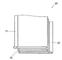
- the electrode bundle 20 is formed by offset lamination of a positive electrode plate 21 and a negative electrode plate 22 made of metal foil with a separator 23 interposed therebetween.
- the electrode bundle 20 according to the present embodiment is formed by winding a strip-shaped positive electrode plate 21 and a negative electrode plate 22 in a flat shape via a separator 23.
- the active material is applied to the strip-shaped positive electrode plate 21 and the negative electrode plate 22 in portions where the both overlap each other.
- the short circuit test of the secondary battery is a test corresponding to a so-called "nail penetration test", and as shown in FIG. 4, the rod member 100 of a predetermined shape provided in the short circuit test apparatus is
- the safety evaluation of the secondary battery 10 is performed in a state in which the through hole 15 is formed by piercing at a predetermined speed from one surface side of the secondary battery 10 and the internal short circuit is forcibly generated. For example, the safety evaluation is performed based on a change in battery voltage, battery temperature, and the like when the through hole 15 is formed in the secondary battery 10.
- the short-circuit testing apparatus for a secondary battery does not use a nail having a conical tip as in the prior art, as will be described in detail below.
- the feature is that a rod-shaped member 100 having a predetermined shape is used.
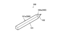
- the rod-like member 100 provided in the short-circuit testing apparatus for a secondary battery is a main body 101 having substantially the same diameter in the axial direction, and a main body And a pointed pointed end 102 provided on one end side of the metal 101.
- the main body portion 101 is formed in a cylindrical shape, and as shown in FIG. 5B, the cross section thereof is substantially circular.
- the pointed end portion 102 is formed in a quadrangular pyramid shape, and as shown in FIG. 5C, the cross section thereof is a quadrangle (substantially square). Therefore, four corners 102 a exist on the circumferential surface of the pointed end 102.
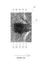
- FIG. 6 is an X-ray CT showing the cross-sectional shape in the thickness direction of the electrode bundle 20 in which the through holes 15 are formed by piercing the rod-like member 100 having the square pyramidal pointed portion 102 as described above into the secondary battery 10.
- FIG. 7 is an X-ray CT image showing a cross-sectional shape of the electrode bundle 20 corresponding to the line A1-A1 to the line E1-E1 in FIG. 8 is an X-ray CT image showing a cross-sectional shape in the thickness direction of the electrode bundle 20 in which the through hole 15 is formed by piercing the secondary battery 10 with a conical tip at its tip
- FIG. 16 is an X-ray CT image showing a cross-sectional shape of the electrode bundle 20 corresponding to A2-A2 line to E2-E2 line of FIG.
- each corner portion 102a constitutes a cutting portion 200 that causes the electrode bundle 20 to have a crack 25 (see FIG. 5).
- each corner 102a cutting part 200
- each corner 102a is not only at the tip but also in a predetermined range from the tip.
- the rod-like member 100 is pierced into the secondary battery 10 in a predetermined direction (fixed direction) to form the through holes 15.
- the crack 25 can be generated at a substantially fixed position of the electrode bundle 20. Therefore, the shape of the through hole 15 can be stabilized, and the stability of the test result can be improved along with the shape stability of the through hole 15.
- the shape of the through holes 15 formed in the electrode bundle 20 can be greatly stabilized, Along with that, the stability of the test results is improved.
- the direction in which the rod-like member 100 is pierced into the secondary battery 10 may be appropriately determined, but in the case where the electrode bundle 20 is enclosed in the battery case 50 in a state of receiving tensile stress in a predetermined direction, It is preferable to arrange the portion 102 a on a straight line orthogonal to the predetermined direction.
- the positive electrode plate 21 and the like are wound in the vertical direction of the secondary battery 10 to be formed. For this reason, as shown in FIG. 10, the electrode bundle 20 is subjected to tensile stress in the vertical direction of the secondary battery 10.
- the two corner portions 102a facing each other are disposed on a straight line in the left-right direction orthogonal to the vertical direction of the secondary battery 10 to form the through hole 15 Is preferred. That is, it is preferable to form the crack 25 on the straight line in the left-right direction.
- the tensile stress of the electrode bundle 20 acts on the crack 25 formed in the electrode bundle 20 in the direction of opening the crack 25.
- the position where the crack 25 is formed in the electrode bundle 20 and the direction in which the crack 25 travels become more stable, and the shape of the through hole 15 becomes more stable accordingly.
- the rod-like member 100 when piercing the rod-like member 100 into the secondary battery 10, the rod-like member 100 may be pierced into the secondary battery 10 until the corner portion 102a constituting the cutting portion 200 reaches the other surface side of the secondary battery 10.
- the through hole 15 it is preferable that the through hole 15 be formed by piercing until the pointed end portion 102 of the rod-like member 100 is completely exposed on the other surface side of the secondary battery 10. Thereby, the shape of the through hole 15 can be further stabilized.
- a nail-like member in which the main body portion 101 has a cylindrical shape and the pointed end portion 102 has a quadrangular pyramid shape, ie, a substantially square cross section is used as the rod member 100.
- the shape is not limited to this shape.
- the cross section of the pointed portion 102 is not limited to a square, and may be, for example, a rhombus, another polygon such as a hexagon or an octagon, or a star.
- the main body portion 101 of the rod-like member 100 may have a polygonal cross section in accordance with the shape of the pointed end portion 102.
- the cross section of the main body portion 101 may be square.
- the corner portions 102a and 101a constituting the cutting portion 200 may be continuously provided from the pointed end portion 102 to the main body portion 101.
- the pointed end portion 102 does not necessarily have to be sharp and sharp at the tip, and for example, as shown in FIG. 12, the tip may be formed in a minus (minus) shape.
- the shape of the through hole 15 can be obtained by arranging the minus shape of the tip along the direction orthogonal to the direction of the tensile stress of the electrode bundle 20 as described above. In particular, it can be stabilized effectively.
- the rod-like member 100 may be a nail-like member configured of a prismatic main body portion 101 and a conical pointed portion 102.
- the corner portion 101 a present in the main body portion 101 functions as the cutting portion 200.
- the rod-like member 100 is configured by a cylindrical main body portion 101 and a conical pointed end portion 102, and a part of the circumferential surface of the main body portion 101 in the radial direction A protruding protrusion 110 may be provided.
- the protruding portion 110 functions as the cutting portion 200.
- the shape of the through-hole 15 is stable by piercing the rod-like member 100 in a predetermined direction with respect to the secondary battery 10 to form the through-hole 15.
- the stability of the test results can be improved accordingly.
- the above-mentioned secondary battery short circuit test device is suitably used for a short circuit test of a vehicle secondary battery
- the application of the secondary battery is not limited to a vehicle.
- the short-circuit test apparatus for a secondary battery according to the present invention is also adopted, for example, for a short-circuit test for a secondary battery mounted on a household auxiliary power supply, various AV devices, personal computers, mobile phones, etc. It is something that can be done.
Landscapes
- Engineering & Computer Science (AREA)
- Manufacturing & Machinery (AREA)
- Chemical & Material Sciences (AREA)
- Chemical Kinetics & Catalysis (AREA)
- Electrochemistry (AREA)
- General Chemical & Material Sciences (AREA)
- Power Engineering (AREA)
- Physics & Mathematics (AREA)
- General Physics & Mathematics (AREA)
- Secondary Cells (AREA)
- Tests Of Electric Status Of Batteries (AREA)
- Charge And Discharge Circuits For Batteries Or The Like (AREA)
Abstract
二次電池の一方面側から突き刺して二次電池に貫通孔を形成する金属製の棒状部材100を有し、棒状部材100が、横断面の周縁部に設けられた角部101a,102aを含み電極束の貫通孔の周縁部に亀裂を生じさせる切断部200を有する構成とする。
Description
本発明は、集電束がケース内に封入されてなる二次電池の短絡試験装置に関し、具体的には、金属製の突起物を突き刺して強制的に内部短絡を発生させた状態で安全評価を行う二次電池の短絡試験装置に関する。
近年、電気自動車(BEV)やプラグインハイブリッド自動車(PHEV)等の電動車両が多数実用化されている。このような電動車両には、走行用モータに電力を供給するためのリチウムイオン電池等の二次電池(高圧バッテリ)が搭載されている。この二次電池は、例えば、正極板と負極板とがセパレータを介して積層された積層体で形成される電極束を備え、この電極束をケース内に封入することによって形成されている。
そして、このような構成の二次電池を製造する際には、短絡時の安全評価を行う二次電池の短絡試験が行われている。具体的には、短絡試験装置によって、釘等の金属製の突起物をケースの外側から二次電池に突き刺して強制的に内部短絡を発生させるいわゆる「釘刺し試験」を実施し、この状態で二次電池の安全評価を行っていた(例えば、特許文献1,2等参照)。
上述のような短絡試験装置を用いた「釘刺し試験」を行うことで、比較的容易に二次電池の安全評価を行うことができる。しかしながら、上述した従来の短絡試験装置では、試験結果が不安定になりやすいという問題がある。具体的には、短絡試験装置による「釘刺し試験」には、一般的に、先端部が円錐状の釘が用いられる。このため、釘を刺した際に二次電池を構成する電極板の割れ方が不規則になりやすく、同一の試験条件で短絡試験(釘刺し試験)を行った場合でも試験結果にばらつきが生じやすいという問題がある。
本発明は、このような事情に鑑みてなされたものであり、試験結果の安定性を高めることができる二次電池の短絡試験装置を提供することを目的とする。
上記課題を解決する本発明の第1の態様は、正極板及び負極板を備える電極束がケース内に封入されて構成された二次電池に貫通孔を形成し、強制的に内部短絡を発生させた状態で前記二次電池の安全評価を行う二次電池の短絡試験装置であって、前記二次電池の一方面側から突き刺して当該二次電池に前記貫通孔を形成する金属製の棒状部材を有し、該棒状部材は、横断面の周縁部に設けられた角部を含み前記電極束の前記貫通孔の周縁部に亀裂を生じさせる切断部を有することを特徴とする二次電池の短絡試験装置にある。
かかる第1の態様では、切断部を備える棒状部材を一定の向きで二次電池に突き刺すことで、電極束の所定位置に亀裂が形成される。したがって、電極束(電極板)の割れ方が規則的になり易い。
かかる第1の態様では、切断部を備える棒状部材を一定の向きで二次電池に突き刺すことで、電極束の所定位置に亀裂が形成される。したがって、電極束(電極板)の割れ方が規則的になり易い。
本発明の第2の態様は、第1の態様の二次電池の短絡試験装置において、前記切断部は、先端部から後方にかけて横断面が多角形であり、その周縁部に形成される角部によって前記電極束に前記亀裂を生じさせることを特徴とする二次電池の短絡試験装置にある。
かかる第2の態様では、比較的簡単な形状の棒状部材で、電極束に亀裂を良好に形成することができる。
かかる第2の態様では、比較的簡単な形状の棒状部材で、電極束に亀裂を良好に形成することができる。
本発明の第3の態様は、第2の態様の二次電池の短絡試験装置において、前記切断部は、横断面が四角形であることを特徴とする二次電池の短絡試験装置にある。
かかる第3の態様では、比較的簡単な形状の棒状部材で、電極束に亀裂を良好に形成することができる。
かかる第3の態様では、比較的簡単な形状の棒状部材で、電極束に亀裂を良好に形成することができる。
本発明の第4の態様は、第1から3の何れか一つの態様の二次電池の短絡試験装置において、前記棒状部材は、軸方向に亘って略同一径の本体部と、該本体部の一端側に設けられる先の尖った尖端部と、を備える釘状部材であり、前記切断部が前記尖端部に設けられていることを特徴とする二次電池の短絡試験装置にある。
かかる第4の態様では、棒状部材として尖端部に切断部が設けられた釘状部材を用いることで、棒状部材(釘状部材)を比較的容易に二次電池に突き刺して貫通孔を形成することができる。
かかる第4の態様では、棒状部材として尖端部に切断部が設けられた釘状部材を用いることで、棒状部材(釘状部材)を比較的容易に二次電池に突き刺して貫通孔を形成することができる。
本発明の第5の態様は、第4の態様の二次電池の短絡試験装置において、前記切断部は、前記尖端部から前記本体部に亘って連続的に設けられていることを特徴とする二次電池の短絡試験装置にある。
かかる第5の態様では、電極束の所定位置に亀裂をより確実に形成でき、電極束(電極板)の割れ方がさらに規則的になり易い。
かかる第5の態様では、電極束の所定位置に亀裂をより確実に形成でき、電極束(電極板)の割れ方がさらに規則的になり易い。
本発明の第6の態様は、第1から5の何れか一つの態様の二次電池の短絡試験装置において、前記電極束が所定方向で引張り応力を受けた状態で前記ケース内に封入されている場合、前記棒状部材は、前記切断部を前記所定方向とは直交する直線上に配置した状態で前記二次電池に突き刺されることを特徴とする二次電池の短絡試験装置にある。
かかる第6の態様では、貫通孔を形成後、電極束には亀裂を開く方向の力が作用する。したがって、電極束(電極板)の割れ方がより規則的になり易い。
かかる第6の態様では、貫通孔を形成後、電極束には亀裂を開く方向の力が作用する。したがって、電極束(電極板)の割れ方がより規則的になり易い。
本発明の第7の態様は、第1から6の何れか一つの態様の二次電池の短絡試験装置において、前記棒状部材は、前記切断部が前記二次電池の他方面側に達するまで前記二次電池に突き刺されることを特徴とする二次電池の短絡試験装置にある。
かかる第7の態様では、電極束の厚さ方向に棒状部材を突き刺して貫通孔を形成する際、電極束の厚さ方向に亘って亀裂が連続的に形成される。
かかる第7の態様では、電極束の厚さ方向に棒状部材を突き刺して貫通孔を形成する際、電極束の厚さ方向に亘って亀裂が連続的に形成される。
かかる本発明に係る二次電池の短絡試験装置によれば、二次電池に、釘状部材等の棒状部材を突き刺して貫通孔を形成する際、電極束の所定位置に亀裂が形成される。したがって、電極束(電極板)の割れ方が規則的になり、試験結果のばらつきも小さく抑えられる。
以下、本発明の一実施形態について図面を参照して詳細に説明する。
まずは、二次電池の構造の一例について簡単に説明する。図1及び図2に示すように、二次電池10は、例えば、リチウムイオン電池である密閉形電池であり、正極板21及び負極板22を備える電極束(エレメント)20と、集電体30,40とが非水電解液(図示なし)と共に電池ケース50内に収容されている。この電池ケース50の上部は、蓋部材60で密閉されている。なお図示は省略するが、電池ケース50内には電池ケース50の内面を覆う絶縁部材が設けられており、電池ケース50と内部に収容される電極束20及び集電体30,40との絶縁が図られている。
まずは、二次電池の構造の一例について簡単に説明する。図1及び図2に示すように、二次電池10は、例えば、リチウムイオン電池である密閉形電池であり、正極板21及び負極板22を備える電極束(エレメント)20と、集電体30,40とが非水電解液(図示なし)と共に電池ケース50内に収容されている。この電池ケース50の上部は、蓋部材60で密閉されている。なお図示は省略するが、電池ケース50内には電池ケース50の内面を覆う絶縁部材が設けられており、電池ケース50と内部に収容される電極束20及び集電体30,40との絶縁が図られている。
電極束20の正極板21には集電体30の一端側が接続され、この集電体30の他端側には、蓋部材60に設けられた貫通部61から外部に突出する正極端子部材70が接続されている。負極板22には集電体40の一端側が接続されている。この集電体40の他端側には、蓋部材60に設けられた貫通部61から外部に突出する負極端子部材80が接続されている。
蓋部材60の上下面側には、各貫通部61の開口部に対応して絶縁シート部材90がそれぞれ設けられている。正極端子部材70及び負極端子部材80は、この絶縁シート部材90によって蓋部材60との絶縁が図られている。
電極束20は、図3に示すように、例えば、金属箔からなる正極板21と負極板22とがセパレータ23を介してオフセット積層されて形成されている。本実施形態に係る電極束20は、セパレータ23を介して帯状の正極板21及び負極板22を扁平形状に捲回されて形成されている。なお帯状の正極板21及び負極板22には、両者が重なる部分に、それぞれ活物質が塗布されている。
このような構成の二次電池10を製造した際には、二次電池の短絡試験装置を用いた安全性試験としての短絡試験が実施される。二次電池の短絡試験とは、いわゆる「釘刺し試験」に相当する試験であり、図4に示すように、短絡試験装置が備える所定形状の棒状部材100を、電極束20が封入された二次電池10の一方面側から所定スピードで突き刺して貫通孔15を形成し、強制的に内部短絡を発生させた状態で二次電池10の安全評価を行うものである。安全評価は、例えば、二次電池10に貫通孔15が形成される際の電池電圧、電池温度等を検出し、その変化に基づいて行われる。
そして、本発明に係る二次電池の短絡試験装置は、二次電池10に突き刺す棒状部材100を、従来のように先端が円錐形の釘を用いるのではなく、以下に詳しく説明するように、所定形状の棒状部材100を用いたところに特徴がある。
具体的には、本実施形態に係る二次電池の短絡試験装置が備える棒状部材100は、図5(a)に示すように、軸方向に亘って略同一径の本体部101と、本体部101の一端側に設けられる先の尖った尖端部102と、を備える金属製の釘状部材である。本体部101は、円柱状に形成され、図5(b)に示すように、その横断面は略円形である。一方、尖端部102は、四角錐状に形成され、図5(c)に示すように、その横断面は四角形(略正方形)である。したがって尖端部102の周面には4つ角部102aが存在する。
このような棒状部材100を二次電池10に対して所定の向きで突き刺して貫通孔15を形成し、強制的に内部短絡を発生させることで、二次電池の短絡試験における試験結果の安定性を高めることができる。
図6は、上記のように四角錐状の尖端部102を備える棒状部材100を二次電池10に突き刺すことで貫通孔15を形成した電極束20の厚さ方向の断面形状を示すX線CT画像であり、図7は、図6のA1-A1線からE1-E1線に対応する電極束20の断面形状を示すX線CT画像である。また図8は、先端が円錐状の釘を二次電池10に突き刺すことで貫通孔15を形成した電極束20の厚さ方向の断面形状を示すX線CT画像であり、図9は、図8のA2-A2線からE2-E2線に対応する電極束20の断面形状を示すX線CT画像である。
上述のように棒状部材100を二次電池10に突き刺して貫通孔15を形成すると、尖端部102の各角部102aによって電極束20の貫通孔15の周縁部が切り裂かれる。図6及び図7に示すように、電極束20には、各角部102aに対応する位置に亀裂25が形成される。すなわち各角部102aは、電極束20に亀裂25を生じさせる切断部200を構成する(図5参照)。そして、このような各角部102a(切断部200)が、棒状部材100の先端部から後方にかけて設けられていることで、すなわち各角部102aが先端部だけでなく、先端部から所定範囲に連続的に設けられていることで、電極束20に亀裂25が形成される位置や亀裂25が進行する方向を制御することができる。
具体的には、二次電池の短絡試験を実施する際には、棒状部材100を二次電池10に対して所定の向き(決まった向き)で突き刺して貫通孔15を形成する。これにより、電極束20のほぼ決まった位置に亀裂25を生じさせることができる。したがって、貫通孔15の形状を安定させることができ、また貫通孔15の形状安定に伴って試験結果の安定性を向上することができる。
一方、従来のように先端が円錐状の釘を二次電池10に突き刺して貫通孔15を形成した場合には、図8及び図9の画像から分かるように、貫通孔15に不規則な亀裂が生じてしまい、貫通孔15の形状が安定しない。
このような画像を比較することで明らかであるが、本発明に係る二次電池の短絡試験装置によれば、電極束20に形成される貫通孔15の形状を大幅に安定させることができ、それに伴って試験結果の安定性が向上する。
ここで、棒状部材100を二次電池10に突き刺す方向は、適宜決定されればよいが、電極束20が所定方向で引張り応力を受けた状態で電池ケース50内に封入されている場合、角部102aを上記所定方向とは直交する直線上に配置することが好ましい。例えば、本実施形態に係る二次電池10の電極束20は、正極板21等が二次電池10の上下方向に捲回されて形成されている。このため、図10に示すように、電極束20には、二次電池10の上下方向で引張り応力を受けている。したがって、このような二次電池10の場合には、二次電池10の上下方向とは直交する左右方向の直線上に相対向する二つの角部102aを配置して貫通孔15を形成することが好ましい。すなわち、この左右方向の直線上に亀裂25が形成されるようにすることが好ましい。
これにより、電極束20に形成された亀裂25には、電極束20の引張り応力が亀裂25を開く方向に作用することになる。これにより、電極束20に亀裂25が形成される位置や亀裂25が進行する方向がより安定し、それに伴い貫通孔15の形状もより安定する。
また棒状部材100を二次電池10に突き刺す際には、切断部200を構成する角部102aが、二次電池10の他方面側に達するまで、棒状部材100を二次電池10に突き刺すことが好ましい。例えば、本実施形態の場合、棒状部材100の尖端部102が二次電池10の他方面側に完全に露出するまで突き刺して貫通孔15を形成することが好ましい。これにより、貫通孔15の形状をさらに安定させることができる。
さらに本実施形態では、棒状部材100として、本体部101が円柱状であり、尖端部102が四角錐状、すなわち横断面が略正方形である釘状部材を用いるようにしたが、棒状部材100の形状は、この形状に限定されるものではない。例えば、尖端部102の横断面は、正方形に限定されず、例えば、菱形としてもよいし、六角形、八角形等の他の多角形としてもよく、或いは星形等としてもよい。
また例えば、棒状部材100の本体部101は、尖端部102の形状に合わせて横断面が多角形になるようにしてもよい。例えば、図11に示すように、尖端部102の横断面が正方形である場合には、本体部101の横断面を正方形としてもよい。この場合、本体部101の周面には、尖端部102の角部102aから連続する角部101aが存在することになる。このように棒状部材100は、切断部200を構成する角部102a,101aが尖端部102から本体部101に亘って連続的に設けられていてもよい。
また尖端部102は、必ずしも先端が鋭く尖っていなくてもよく、例えば、図12に示すように、先端が-(マイナス)形状となるように形成されていてもよい。尖端部102をこのような形状とした場合、先端のマイナス形状が、上述のように電極束20の引張り応力の方向とは直交する方向に沿うように配置することで、貫通孔15の形状を特に効果的に安定させることができる。
また棒状部材100は、例えば、図13に示すように、角柱状の本体部101と、円錐形状の尖端部102とで構成される釘状部材であってもよい。この構成では、本体部101に存在する角部101aが切断部200として機能する。さらには、棒状部材100は、例えば、図14に示すように、円柱状の本体部101と、円錐状の尖端部102とで構成され、本体部101の周面の一部に、径方向に突出する突出部110が設けられたものであってもよい。この構成では、突出部110が切断部200として機能する。
このように棒状部材100が切断部200を備えていれば、この棒状部材100を二次電池10に対して所定の向きで突き刺して貫通孔15を形成することで、貫通孔15の形状が安定し、それに伴って試験結果の安定性を向上することができる。
以上、本発明の実施形態について説明したが、勿論、本発明は上述の実施形態に限定されるものではない。本発明は、その趣旨を逸脱しない範囲で適宜変更が可能なものである。
例えば、上述した二次電池の短絡試験装置は、車両用の二次電池の短絡試験にも好適に用いられるものであるが、二次電池の用途は車両用に限定されるものではない。本発明に係る二次電池の短絡試験装置は、例えば、家庭用の補助電源、各種AV機器、パソコン、携帯電話など、車両以外の他の機器に搭載される二次電池の短絡試験にも採用することができるものである。
10 二次電池
15 貫通孔
20 電極束
21 正極板
22 負極板
23 セパレータ
25 亀裂
30 集電体
40 集電体
50 電池ケース
60 蓋部材
61 貫通部
70 正極端子部材
80 負極端子部材
90 絶縁シート部材
100 棒状部材
101 本体部
101a 角部
102 尖端部
102a 角部
110 突出部
200 切断部
15 貫通孔
20 電極束
21 正極板
22 負極板
23 セパレータ
25 亀裂
30 集電体
40 集電体
50 電池ケース
60 蓋部材
61 貫通部
70 正極端子部材
80 負極端子部材
90 絶縁シート部材
100 棒状部材
101 本体部
101a 角部
102 尖端部
102a 角部
110 突出部
200 切断部
Claims (7)
- 正極板及び負極板を備える電極束がケース内に封入されて構成された二次電池に貫通孔を形成し、強制的に内部短絡を発生させた状態で前記二次電池の安全評価を行う二次電池の短絡試験装置であって、
前記二次電池の一方面側から突き刺して当該二次電池に前記貫通孔を形成する金属製の棒状部材を有し、
該棒状部材は、横断面の周縁部に設けられた角部を含み前記電極束の前記貫通孔の周縁部に亀裂を生じさせる切断部を有することを特徴とする二次電池の短絡試験装置。 - 請求項1に記載の二次電池の短絡試験装置において、
前記切断部は、先端部から後方にかけて横断面が多角形であり、その周縁部に形成される角部によって前記電極束に前記亀裂を生じさせることを特徴とする二次電池の短絡試験装置。 - 請求項2に記載の二次電池の短絡試験装置において、
前記切断部は、横断面が四角形であることを特徴とする二次電池の短絡試験装置。 - 請求項1から3の何れか一項に記載の二次電池の短絡試験装置において、
前記棒状部材は、軸方向に亘って略同一径の本体部と、該本体部の一端側に設けられる先の尖った尖端部と、を備える釘状部材であり、
前記切断部が前記尖端部に設けられていることを特徴とする二次電池の短絡試験装置。 - 請求項4に記載の二次電池の短絡試験装置において、
前記切断部は、前記尖端部から前記本体部に亘って連続的に設けられていることを特徴とする二次電池の短絡試験装置。 - 請求項1から5の何れか一項に記載の二次電池の短絡試験装置において、
前記電極束が所定方向で引張り応力を受けた状態で前記ケース内に封入されている場合、
前記棒状部材は、前記切断部を前記所定方向とは直交する直線上に配置した状態で前記二次電池に突き刺されることを特徴とする二次電池の短絡試験装置。 - 請求項1から6の何れか一項に記載の二次電池の短絡試験装置において、
前記棒状部材は、前記切断部が前記二次電池の他方面側に達するまで前記二次電池に突き刺されることを特徴とする二次電池の短絡試験装置。
Applications Claiming Priority (2)
| Application Number | Priority Date | Filing Date | Title |
|---|---|---|---|
| JP2014125785A JP2016004722A (ja) | 2014-06-18 | 2014-06-18 | 二次電池の短絡試験装置 |
| JP2014-125785 | 2014-06-18 |
Publications (1)
| Publication Number | Publication Date |
|---|---|
| WO2015194441A1 true WO2015194441A1 (ja) | 2015-12-23 |
Family
ID=54935428
Family Applications (1)
| Application Number | Title | Priority Date | Filing Date |
|---|---|---|---|
| PCT/JP2015/066786 Ceased WO2015194441A1 (ja) | 2014-06-18 | 2015-06-10 | 二次電池の短絡試験装置 |
Country Status (2)
| Country | Link |
|---|---|
| JP (1) | JP2016004722A (ja) |
| WO (1) | WO2015194441A1 (ja) |
Cited By (1)
| Publication number | Priority date | Publication date | Assignee | Title |
|---|---|---|---|---|
| AT523935B1 (de) * | 2020-12-09 | 2022-01-15 | Univ Graz Tech | Impaktor zum Prüfen von Batteriezellen |
Families Citing this family (3)
| Publication number | Priority date | Publication date | Assignee | Title |
|---|---|---|---|---|
| JP7062891B2 (ja) * | 2017-07-12 | 2022-05-09 | 日本電気株式会社 | 電池の内部短絡試験法と内部短絡試験装置 |
| JP7069670B2 (ja) * | 2017-12-04 | 2022-05-18 | コニカミノルタ株式会社 | X線撮影システム |
| KR102951385B1 (ko) | 2021-11-10 | 2026-04-10 | 주식회사 엘지에너지솔루션 | 전지셀 측면의 관통 시험 장치 및 이를 이용한 전지셀의 관통 시험 방법 |
Citations (4)
| Publication number | Priority date | Publication date | Assignee | Title |
|---|---|---|---|---|
| JP2008210617A (ja) * | 2007-02-26 | 2008-09-11 | Sony Corp | 電極構造体およびその製造方法、ならびに電池およびその製造方法 |
| JP2011003513A (ja) * | 2009-06-22 | 2011-01-06 | Kobelco Kaken:Kk | 安全性評価試験方法およびその試験装置 |
| JP2012215537A (ja) * | 2011-03-25 | 2012-11-08 | Sharp Corp | 安全性評価試験方法、安全性評価試験装置、および熱電対付破壊測定器具 |
| JP2014049421A (ja) * | 2012-09-04 | 2014-03-17 | Toyota Industries Corp | 蓄電装置、及び蓄電装置の製造方法 |
-
2014
- 2014-06-18 JP JP2014125785A patent/JP2016004722A/ja active Pending
-
2015
- 2015-06-10 WO PCT/JP2015/066786 patent/WO2015194441A1/ja not_active Ceased
Patent Citations (4)
| Publication number | Priority date | Publication date | Assignee | Title |
|---|---|---|---|---|
| JP2008210617A (ja) * | 2007-02-26 | 2008-09-11 | Sony Corp | 電極構造体およびその製造方法、ならびに電池およびその製造方法 |
| JP2011003513A (ja) * | 2009-06-22 | 2011-01-06 | Kobelco Kaken:Kk | 安全性評価試験方法およびその試験装置 |
| JP2012215537A (ja) * | 2011-03-25 | 2012-11-08 | Sharp Corp | 安全性評価試験方法、安全性評価試験装置、および熱電対付破壊測定器具 |
| JP2014049421A (ja) * | 2012-09-04 | 2014-03-17 | Toyota Industries Corp | 蓄電装置、及び蓄電装置の製造方法 |
Cited By (2)
| Publication number | Priority date | Publication date | Assignee | Title |
|---|---|---|---|---|
| AT523935B1 (de) * | 2020-12-09 | 2022-01-15 | Univ Graz Tech | Impaktor zum Prüfen von Batteriezellen |
| AT523935A4 (de) * | 2020-12-09 | 2022-01-15 | Univ Graz Tech | Impaktor zum Prüfen von Batteriezellen |
Also Published As
| Publication number | Publication date |
|---|---|
| JP2016004722A (ja) | 2016-01-12 |
Similar Documents
| Publication | Publication Date | Title |
|---|---|---|
| US10326169B2 (en) | Method for manufacturing prismatic secondary battery | |
| KR101167790B1 (ko) | 권회형 전지 및 권회형 전지의 제조 방법 | |
| JP6631792B2 (ja) | 二次電池の短絡評価方法 | |
| JP2011049147A (ja) | 二次電池 | |
| JP6090579B2 (ja) | 蓄電装置 | |
| WO2015194441A1 (ja) | 二次電池の短絡試験装置 | |
| JP6848645B2 (ja) | 集電積層体 | |
| KR102355109B1 (ko) | 용접용 기둥을 포함하는 원통형 이차전지 | |
| JPWO2017017930A1 (ja) | 捲回型電池 | |
| JP2019061949A (ja) | 蓄電装置、及び蓄電装置のレーザ溶接方法 | |
| EP2437341A2 (en) | Lithium ion storage device | |
| JP2014154291A (ja) | 電池 | |
| JP2012054024A (ja) | 角形二次電池およびその製造方法 | |
| EP2946868B1 (en) | Method of manufacturing a sealed battery | |
| JP2016195014A (ja) | 蓄電素子 | |
| KR20170009592A (ko) | 원통형 이차전지 | |
| JP7068632B2 (ja) | 電池 | |
| JP7110010B2 (ja) | 二次電池 | |
| JP6086210B2 (ja) | 蓄電素子の製造方法 | |
| JP2016195025A (ja) | 蓄電素子 | |
| KR20070081549A (ko) | 젤리-롤형 전극조립체 제조용 권심 | |
| JP2015082495A (ja) | 蓄電装置用の仮封止栓 | |
| JP2017188392A (ja) | 電池 | |
| JP2019046613A (ja) | 蓄電装置 | |
| US20160049683A1 (en) | Secondary battery and method of manufacturing the same |
Legal Events
| Date | Code | Title | Description |
|---|---|---|---|
| 121 | Ep: the epo has been informed by wipo that ep was designated in this application |
Ref document number: 15809162 Country of ref document: EP Kind code of ref document: A1 |
|
| NENP | Non-entry into the national phase |
Ref country code: DE |
|
| 122 | Ep: pct application non-entry in european phase |
Ref document number: 15809162 Country of ref document: EP Kind code of ref document: A1 |