WO2015194401A1 - 冷間プレス成形(cold press forming)方法 - Google Patents
冷間プレス成形(cold press forming)方法 Download PDFInfo
- Publication number
- WO2015194401A1 WO2015194401A1 PCT/JP2015/066384 JP2015066384W WO2015194401A1 WO 2015194401 A1 WO2015194401 A1 WO 2015194401A1 JP 2015066384 W JP2015066384 W JP 2015066384W WO 2015194401 A1 WO2015194401 A1 WO 2015194401A1
- Authority
- WO
- WIPO (PCT)
- Prior art keywords
- shape
- molding
- cross
- press
- press molding
- Prior art date
- Legal status (The legal status is an assumption and is not a legal conclusion. Google has not performed a legal analysis and makes no representation as to the accuracy of the status listed.)
- Ceased
Links
Images








Classifications
-
- B—PERFORMING OPERATIONS; TRANSPORTING
- B21—MECHANICAL METAL-WORKING WITHOUT ESSENTIALLY REMOVING MATERIAL; PUNCHING METAL
- B21D—WORKING OR PROCESSING OF SHEET METAL OR METAL TUBES, RODS OR PROFILES WITHOUT ESSENTIALLY REMOVING MATERIAL; PUNCHING METAL
- B21D22/00—Shaping without cutting, by stamping, spinning, or deep-drawing
- B21D22/20—Deep-drawing
- B21D22/26—Deep-drawing for making peculiarly, e.g. irregularly, shaped articles
-
- B—PERFORMING OPERATIONS; TRANSPORTING
- B62—LAND VEHICLES FOR TRAVELLING OTHERWISE THAN ON RAILS
- B62D—MOTOR VEHICLES; TRAILERS
- B62D25/00—Superstructure or monocoque structure sub-units; Parts or details thereof not otherwise provided for
- B62D25/04—Door pillars ; windshield pillars
Definitions
- the present invention relates to a cold press forming method for manufacturing a center pillar part having a curved portion that is curved while changing its sectional height in the longitudinal direction.
- Such super high-tensile material has high strength, while ductility as a steel sheet is reduced. Therefore, molding defects such as cracks and wrinkles are likely to occur in ultra high tensile materials during press molding. For this reason, various press molding techniques have been studied in order to produce products free of cracks and wrinkles.
- drawing is a method of forming a material with a punch and a die while restraining the material with a die and a blank holder.
- a highly ductile 590 MPa class steel sheet is used as a material for an automobile part
- the automobile part can be drawn without causing cracks or wrinkles in the steel sheet as the material.
- an ultra-high tensile material having a small ductility is used as a material for an automobile part, if the material (steel sheet) is constrained by a wrinkle presser, cracking is likely to occur in the ultra-high tensile material as the material.
- Foam molding is a method in which a material is bent while being bent with an upper tool and a lower tool. Foam molding is often used for press molding of ultra-high-tensile materials with low ductility because deformation applied to the material can be minimized. Form molding is an effective pressing method for reducing press working force.
- foam molding can be applied to press molding of a part having a simple cross-sectional shape in the longitudinal direction, such as a rocker (side sill) part.
- foam molding is applicable to press molding of parts targeted by the present invention, specifically, press molding of center pillar parts having curved portions that are curved while changing the cross-sectional height in the longitudinal direction. difficult.
- a third method a method of avoiding occurrence of cracks and wrinkles by two-step press molding, in which a material is drawn to the extent that no cracking occurs, and then the material after the drawing is foamed.
- a general center pillar part is curved with its cross section changing in the longitudinal direction, and when this center pillar part is molded by foam molding, large wrinkles are generated in the flange part of the center pillar part that is largely curved. (For example, see FIG. 10).
- Patent Document 1 proposes a press molding method for reducing wrinkles generated in a curved flange of a center pillar part in hot press molding. This method is a press molding method in which only a curved portion where wrinkles are likely to occur is formed by drawing while enlarging a blank shape and constraining the material with a wrinkle presser, and performing foam molding in other portions. This method has an effect of reducing wrinkles because the material is drawn while restraining the curved portion of the material by pressing the wrinkles.
- Patent Document 1 is hot press forming, and the material is formed with a low material strength by increasing the temperature of the material during forming. For this reason, it is difficult to apply the method described in Patent Document 1 described above to the press working of the super high tensile strength material of the present invention intended for cold press forming.
- the present invention has been made in order to solve the above-described problems, and uses a center pillar component having a curved portion that is curved while changing its cross-sectional height in the longitudinal direction, and uses an ultra-high tensile material of 980 MPa class or higher.
- An object of the present invention is to obtain a cold press molding method that can be produced without generating cracks and wrinkles.
- the cold press forming method according to the present invention has a shape in which two T-shaped vertical sides are opposed to each other at both longitudinal ends (connected T-shape).
- a center pillar part having a curved portion that is curved while changing the cross-sectional height in the longitudinal direction, and has a connected T-shape at both ends in the longitudinal direction.
- a trimming step a part of the top plate portion in the hat cross section of the trimming part is pressed with a pad, and the top plate portion, the side wall portion and the flange portion
- a first molded part having a connecting T-shape at both longitudinal ends, a cross-sectional depth of 10 to 30 mm in the longitudinal direction, and a hat cross-sectional portion in the longitudinal cross-section by drawing.
- the first press forming process (press forming part) is formed by drawing, the trimming process for trimming the first molded part to obtain a trimmed part, and the product shape part, the step shape part, and the inclined surface part are formed by form molding.
- the center pillar part having a curved portion that is curved while changing the cross-sectional height in the longitudinal direction is formed into a product shape even when an ultra-high tensile material of 980 MPa class or higher is used. There is an effect that cold press molding can be performed without generating cracks or wrinkles in the portion (hat cross section).
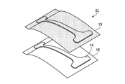
- FIG. 1A is a perspective view of a first mold used in a cold press forming method according to an embodiment of the present invention.
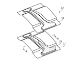
- FIG. 1B is a perspective view of a second mold used in the cold press forming method according to one embodiment of the present invention.
- FIG. 2 is a cross-sectional view taken along the line AA of the second mold shown in FIG. 1B.
- FIG. 3A is a perspective view of a center pillar component that is a molding target of the cold press molding method according to an embodiment of the present invention.
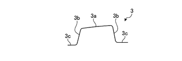
- FIG. 3B is a cross-sectional view of the center pillar part shown in FIG. 3C is a side view of the center pillar component shown in FIG. 3A.
- FIG. 3A is a perspective view of a first mold used in a cold press forming method according to an embodiment of the present invention.
- FIG. 1B is a perspective view of a second mold used in the cold press forming method according to one embodiment of the present invention.
- FIG. 2 is a cross
- FIG. 4A is a perspective view of a first molded part molded in the first press molding step of the cold press molding method according to one embodiment of the present invention.
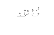
- 4B is a cross-sectional view taken along the line CC of the first molded part shown in FIG. 4A.
- FIG. 5 is a perspective view of the trimming component obtained in the trimming step of the cold press forming method according to the embodiment of the present invention.
- FIG. 6A is a perspective view of a second molded part molded in the second press molding step of the cold press molding method according to one embodiment of the present invention.
- FIG. 6B is a cross-sectional view taken along the line DD of the second molded part shown in FIG. 6A.
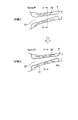
- FIG. 7A is an explanatory view illustrating the first half of the second press molding step in the cold press molding method according to one embodiment of the present invention.
- FIG. 7B is a cross-sectional view taken along the line EE for explaining the first half of the second press molding step shown in FIG. 7A.
- FIG. 8A is an explanatory view illustrating the second half of the second press molding step in the cold press molding method according to one embodiment of the present invention.
- FIG. 8B is a cross-sectional view taken along the line FF for explaining the second half of the second press forming step shown in FIG. 8A.
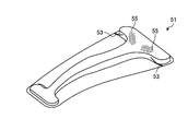
- FIG. 9 is a perspective view showing an example of a center pillar part formed by a press forming method performed for comparison.
- FIG. 10 is a perspective view showing another example of the center pillar part molded by the press molding method performed for comparison.
- a cold press forming method is a cold press forming method for manufacturing a center pillar part 1 (see FIGS. 3A to 3C) by cold press forming, and is drawn in a longitudinal direction by drawing.
- the trimming component 4 has a hat cross-section 10 comprising a top plate 10a, a vertical wall 10b, and a flange 10c.
- the product shape portion 12 to be formed, the step shape portion 31 continuous outside the portion corresponding to the vertical side of the T-shape in the connected T-shape of the trimming component 4, and the step shape portion 31 continuously rising outside the step shape portion 31 A second press molding step of molding the second molded part 9 (see FIGS. 6A and 6B) having the inclined surface portion 33 by foam molding.
- center pillar component 1 will be described first, and then each step of the cold press forming method according to an embodiment of the present invention will be described.
- the center pillar component 1 has a curved portion 5 that is curved while the cross-sectional height changes in the longitudinal direction.
- the center pillar component 1 has a connection T-shape as shown in FIG. 3A.
- the connection T-shape is a shape in which two T-shaped vertical sides are opposed to each other at both longitudinal ends of the center pillar component 1.
- the portion corresponding to the vertical side of the T-shape is such that the longitudinal cross section of the center pillar part 1 has a hat shape. It is formed. In the following description, this part is referred to as a hat cross section 3.
- the hat cross section 3 is continuously formed on the top plate portion 3a, the vertical wall portion 3b formed on the side portion of the top plate portion 3a, and the outside of the vertical wall portion 3b. And a flange portion 3c.
- the boundary portion between the top plate portion 3a and the vertical wall portion 3b is an R shoulder (R-shoulder portion) having a curvature radius R of 5 to 10 mm.
- R-shoulder portion having a curvature radius R of 5 to 10 mm.
- the longitudinal wall part 3b and the flange part 3c do not exist in the longitudinal direction both ends of the center pillar component 1, and the both ends of a T-shaped horizontal side (refer FIG. 3A).
- the center pillar part 1 having the shape as described above is manufactured by cold press molding using a super high tensile material having a strength level of 980 MPa or higher as a blank material.
- each step of the cold press forming method according to the present embodiment will be described together with a mold used in each step and a molded part formed in each step.
- the first press forming step is a cross section of 10 to 30 mm in the longitudinal direction by drawing using the first mold 11 (see FIG. 1A). This is a step of press-molding the first molded part 7 (see FIG. 4A) at a depth.
- die 11 is a metal mold
- die 11 has the die
- the die 13, punch 14, and wrinkle presser 15 of the first mold 11 are configured to mold a blank material such as ultra-high tensile material with a cross-sectional depth of 10 to 30 mm. That is, the depth of the first mold 11 is set to 10 to 30 mm.
- the reason why the lower limit of the depth of the first die 11 is set to 10 mm is that the radius R of the curvature of the R shoulder of the center pillar part 1 described above is 5 to 10 mm. This is because the blank material can be press-molded into the first molded part 7 that is the basis of the center pillar part 1 by the first press-molding process even when the curvature radius R is.
- the reason why the upper limit of the depth of the first mold 11 is set to 30 mm is that when the depth of the first mold 11 exceeds 30 mm, the ultra-high tensile material of 980 MPa class or higher is used as a blank material and drawn. This is because there is a risk that cracking occurs in the first molded part 7 in the first press molding process.
- the first molded part 7 is an intermediate part (interim part) that is press-molded by the first mold 11 in the process of manufacturing the center pillar part 1 from the blank material by the cold press molding method according to the present embodiment.
- the first molded part 7 has a connection T shape at both ends in the longitudinal direction, has a cross-sectional depth within a certain range in the longitudinal direction, and a top plate portion 8a in a cross section perpendicular to the longitudinal direction.
- a hat cross section 8 comprising a vertical wall portion 8b and a flange portion 8c.
- the depth of the cross section along the longitudinal direction of the first molded part 7, that is, the cross-sectional depth of each of the connected T-shaped portion of the first molded part 7 and the hat cross section 8 is 10 to 30 mm.
- the cross-sectional depth of the first molded part 7, that is, the molding depth when the blank material is press-molded into the first molded part 7 by drawing is set to 10 to 30 mm. ing. For this reason, even if drawing using an ultra-high tensile material of 980 MPa or higher as a blank material, it is possible to avoid the occurrence of cracking of the first molded part 7 and hence the cracking of the center pillar part 1. it can.
- the trimming step includes the left and right ends of the portion corresponding to the lateral side of the connected T-shaped T-shape in the first molded part 7 and the flange portion.
- This is a step of trimming the left and right side portions of 8c to obtain the trimming component 4 (see FIG. 5).
- FIG. 5 among the parts constituting the trimming component 4, those similar to the first molded component 7 are denoted by the same reference numerals.
- FIG. 5 the portion trimmed and removed from the first molded part 7 in order to obtain the trimmed part 4 is indicated by hatching.
- the reason for trimming the first molded part 7 in the first press molding process in this way is to facilitate the second press molding process which is the next process. is there.
- the second press forming step uses the second mold 17 (see FIG. 1B) and forms the trimming component 4 by the above-described trimming step. Is press-molded into the second molded part 9 (see FIGS. 6A and 6B). Specifically, in the present embodiment, in the second press molding step, a part of the top plate portion 8a in the hat cross section 8 of the trimming component 4 obtained by trimming the first molding component 7 is replaced with the second mold 17.
- a product shape portion 12 having a hat cross-sectional portion 10 composed of a top plate portion 10a, a vertical wall portion 10b and a flange portion 10c, and a T-shaped vertical side of the connecting T-shape of the trimming component 4
- a second molded part 9 (see FIGS. 6A and 6B) having a step shape portion 31 continuous outside the corresponding portion and an inclined surface portion 33 rising obliquely upward continuously outside the step shape portion 31 This is a step of forming by mold forming using the mold 17.
- the second mold 17 is a mold that is used in the second press molding process and for molding the second molded part 9 from the trimmed part 4 obtained by trimming the first molded part 7 by the trimming process described above.
- the second mold 17 includes a second upper mold 19, a second lower mold 21, and a pad 23.
- the second mold 17 includes a pair of upper and lower product forming portions 25U and 25L as product forming portions for forming the product shape portion 12 of the second molded part 9 (see FIG. 6A). have.
- the second mold 17 has a pair of upper and lower step shape portion forming portions 27U and a step shape portion forming portion 27L as step shape portion forming portions for forming the step shape portion 31 (see FIGS. 6A and 6B).
- the second mold 17 has a pair of upper and lower inclined surface portion forming portions 29U and an inclined surface portion forming portion 29L as inclined surface portion forming portions for forming the inclined surface portion 33 (see FIGS. 6A and 6B).
- the second upper mold 19 has a product molding part 25U, a step shape part molding part 27U, and an inclined surface part molding part 29U.
- the product molding part 25U is formed in a concave shape corresponding to the product shape of the molding object (specifically, the center pillar part 1).
- the step shape portion molding portion 27U is formed on both sides of the product molding portion 25U.
- the inclined surface portion forming portions 29U are formed on both sides of the product forming portion 25U and the step shape portion forming portion 27U.
- the second lower mold 21 has a product molding part 25L, a step shape part molding part 27L, and an inclined surface part molding part 29L.
- the product molding portion 25L is formed in a convex shape corresponding to the product shape of the molding target (specifically, the center pillar component 1).
- the step shape portion molding portion 27L is formed on both sides of the product molding portion 25L.
- the inclined surface portion forming portions 29L are formed on both sides of the product forming portion 25L and the step shape portion forming portion 27L.
- the pad 23 presses a part of the top plate portion 8a in the hat cross section 8 of the trimming component 4 in the second press molding process.
- the pad 23 is provided so as to hold a substantially T-shaped range in the top plate portion 8a (see FIG. 5).
- the pad 23 can suppress a portion of the trimming component 4 where wrinkling is a problem.
- the pad 23 may hold down a wider range of the top plate portion 8a.
- the second molded part 9 is manufactured by press-molding the trimmed part 4 by the second mold 17 in the process of manufacturing the center pillar part 1 from the blank material by the cold press-forming method according to the present embodiment. It is an intermediate part.
- the second molded part 9 includes a product shape part 12 having a hat cross-sectional part 10 including a top plate part 10 a, a vertical wall part 10 b, and a flange part 10 c, and a trimming part 4. It has a step shape portion 31 that continues outside the portion corresponding to the vertical side of the T-shape in the letter shape, and an inclined surface portion 33 that rises obliquely upward continuously to the outside of the step shape portion 31.
- the product shape portion 12 is a portion that is press-molded so as to have the product shape of the target center pillar part 1.
- the hat cross section 10 of the product shape portion 12 is formed so that the cross section in the longitudinal direction of the second molded part 9 has a hat shape.
- the step shape portion 31 is continuous with the outer side of the flange portion 10 c of the hat cross-sectional portion 10 with a step.
- the inclined surface portions 33 are respectively formed outside the step shape portions 31 on both sides of the hat cross-sectional portion 10.
- FIGS. 6A and 6B among the parts constituting the second molded part 9, those similar to the product of the center pillar part 1 (see FIGS. 3A to 3C) are given the same subscripts. Yes.
- the second molded part 9 having the configuration shown in FIGS. 6A and 6B is obtained by trimming the step shape part 31, the inclined surface part 33, etc., so that the center pillar part 1 which is the final product shape (see FIGS. 3A to 3C) )become.
- FIGS. 7A and 7B and FIGS. 8A and 8B are explanatory diagrams of a second press molding step in the cold press molding method according to the embodiment of the present invention.
- FIG. 7A and 7B are diagrams for explaining the first half of the second press molding step in the present embodiment.
- 7A and 7B are diagrams for explaining the state of the part 6 in the middle of the press molding from the trimming part 4 to the second molded part 9, and the state change of the part 6 in the middle of the press molding in the first half of the second press molding process. It is shown in the figure.
- FIG. 7A is a plan view for explaining the wrinkled state of the part 6 in the middle of press forming in the first half of the second press forming step.
- FIG. 7A is a plan view for explaining the wrinkled state of the part 6 in the middle of press forming in the first half of the second press forming step.
- FIG. 7B is a cross-sectional view for explaining the press forming state of the part 6 in the middle of press forming in the first half of the second press forming step, that is, a cross-sectional view taken along the line EE of the part 6 in the middle of press forming shown in FIG. 7A. It is shown in the figure.
- FIG. 7B also shows a cross-sectional view taken along the line EE of the second upper mold 19 and the second lower mold 21 of the second mold 17.
- FIGS. 8A and 8B are diagrams for explaining the second half of the second press molding step in the present embodiment.
- FIGS. 8A and 8B illustrate changes in the state of the part 6 in the middle of the press molding in the latter half of the second press molding process as diagrams for explaining the state of the part 6 in the middle of the press molding described above.
- FIG. 8A shows a plan view for explaining the wrinkled state of the part 6 during the press molding in the second half of the second press molding process.
- FIG. 8B is a cross-sectional view for explaining the press forming state of the part 6 in the middle of press forming in the second half of the second press forming step, that is, a cross-sectional view taken along the line FF of the part 6 in the middle of press forming shown in FIG. 8A. It is shown in the figure.
- FIG. 8B also shows a cross-sectional view taken along the line FF of the second upper mold 19 and the second lower mold 21 of the second mold 17.
- states a to e are during press molding in accordance with the distance to the bottom dead center of the second upper mold 19 in the second press molding process.
- Each state of the part 6 and the second mold 17 is shown. That is, in FIGS. 7A and 7B, the state a is a state where the distance to the bottom dead center of the second upper mold 19 is 30 mm (30 mm UP).
- the state b is a state where the distance to the bottom dead center of the second upper mold 19 is 20 mm (20 mm UP).
- the state c is a state where the distance to the bottom dead center of the second upper mold 19 is 10 mm (10 mm UP).
- the state d is a state where the distance to the bottom dead center of the second upper mold 19 is 5 mm (5 mm UP).
- the state e is a state where the distance to the bottom dead center of the second upper mold 19 is 2 mm (2 mm UP).
- wrinkles 55 generated in the part 6 in the middle of press molding in the second press molding step are indicated by wavy lines.
- the case where the second upper mold 19 is moved to the second lower mold 21 side will be described as an example, and the process in which the second molded part 9 is molded by the second press molding process will be described.
- the moving direction of the second mold 17 is not limited to the downward direction (the direction in which the second upper mold 19 approaches the second lower mold 21).
- the upward direction (the second lower mold 21 is the second direction).
- the direction approaching the upper mold 19) may be used. That is, the moving direction of the second mold 17 may be a direction in which the second upper mold 19 and the second lower mold 21 approach each other. The same applies to the first mold 11 in the first press molding step described above.
- the trimming component 4 is placed on the second lower mold 21, and the second lower mold 21 is in a state of receiving and supporting the trimming component 4.
- the second upper mold 19 moves downward toward the second lower mold 21.
- the second mold 17 presses the second upper mold 19 against the trimming part 4 supported and supported by the second lower mold 21 and starts press molding of the trimming part 4.
- the second mold 17 changes the state of the second upper mold 19 and the second lower mold 21 to the state a shown in FIG. 7B and then to the state b shown in FIG. 7B.
- the second upper mold 19 abuts the step shape portion forming portion 27U against the trimming component 4 being pressed, that is, the component 6 being pressed, as shown in FIG. 7B. (See dotted circle 41 in FIG. 7B).
- the step shape portion molding portion 27U faces the part 6 in the middle of press molding toward the step shape portion molding portion 27L of the second lower mold 21 as indicated by a dotted circle 41 in FIG. 7B. Push.
- the top of the inclined surface of the inclined surface portion molding portion 29L in the second lower mold 21 abuts against the part 6 in the middle of press molding, as shown in FIG. 7B (the dotted circle 43 in FIG. 7B). reference).
- the shoulder portion in the product molding portion 25L of the second lower mold 21 comes into contact with the component 6 in the middle of press molding (see the dotted line circle 45 in FIG. 7B).
- the second upper mold 19 further moves downward from the state b toward the second lower mold 21.
- die 17 further advances the press molding with respect to the component 6 in the middle of press molding.
- the second mold 17 changes the state of the second upper mold 19 and the second lower mold 21 from the state b shown in FIG. 7B to the state c.
- the second upper mold 19 further moves down from the state c toward the second lower mold 21.
- die 17 further advances the press molding with respect to the component 6 in the middle of press molding.
- the second mold 17 changes the state of the second upper mold 19 and the second lower mold 21 from the state c shown in FIG. 7B to the state d shown in FIG. 8B and subsequently to the state e.
- the second upper mold 19 further moves the product molding part 25U and the inclined surface part molding part 29U to the second lower mold 21 as compared with the state c (see FIG. 7B). Move closer.
- the step shape portion molding portion 27U strongly presses the part 6 in the middle of press molding toward the step shape portion molding portion 27L.
- the second upper mold 19 further approaches the second lower mold 21 and presses the part 6 in the middle of press molding more strongly against the second lower mold 21.
- the part 6 in the middle of press molding is in a state of being substantially entirely sandwiched between the second upper mold 19 and the second lower mold 21.
- wrinkles 55 are generated in the extra portion 37 of the part 6 in the middle of press molding due to the increase in the effect of suppressing wrinkles as described above.
- the wrinkles 55 are not generated in the part 35 (for example, the top plate portion 10a or the flange portion 10c) that becomes the product shape.
- the portion 35 having the product shape corresponds to the product shape portion 12 of the second molded part 9 shown in FIG. 6A.
- wrinkles for example, wrinkles 55 illustrated in FIGS. 9 and 10
- the product shape portion 12 for example, the top plate portion 10 a and the flange portion 10 c
- the product molding section 25U shown in FIG. 8B is configured to replace the part 6 in the middle of press molding with the product molding section 25L (see FIG. 7B) of the second lower mold 21 after the state e. To press) and complete the press molding of the part 35 to be the product shape.
- the part 6 in the middle of press molding is press-molded into the second molded part 9 shown in FIG. 6A.
- the second molded part 9 becomes the center pillar part 1 (see FIG. 3A) by trimming the step shape portion 31, the inclined surface portion 33 and the like.
- the hat cross section 10 of the second molded part 9 shown in FIG. 6B corresponds to the hat cross section 3 of the center pillar part 1 shown in FIG. 3B.
- FIG. 9 shows a center pillar part 51 as a comparative part formed by a deep drawing forming process with the goal of forming a center pillar part having the same shape as the center pillar part 1 (see FIG. 3A).
- FIG. 10 shows a center pillar part 57 as a comparative part molded by two steps of drawing molding similar to the present invention and foam molding different from the present invention.
- the portion corresponding to the T-shaped lateral side of the connected T-shaped intermediate part by the drawing process after the drawing process similar to the first press molding process of the present embodiment is performed, the portion corresponding to the T-shaped lateral side of the connected T-shaped intermediate part by the drawing process.
- the left and right ends of the flange and the left and right sides of the flange are trimmed. Trimming parts obtained by this trimming are formed using a mold different from the second press molding step of the present embodiment.
- the center pillar part 57 shown in FIG. 10 was molded.
- the mold used for forming the center pillar part 57 is a mold formed only by the product molding portion in the second mold 17 (see FIG. 1B) of the present embodiment, that is, the step shape portion shown in FIG.
- the mold does not have a molding part (step shape part molding part 27U, step shape part molding part 27L) or an inclined surface part molding part (inclined surface part molding part 29U, inclined surface part molding part 29L).
- the center pillar part 51 formed by one deep drawing process has a substantially T-shape of the R shoulder part, particularly the top plate part, due to the material restraint by the wrinkle presser.
- a crack 53 occurred in the vicinity. Such cracks 53 can be avoided by reducing the wrinkle pressure, but in such a case, as shown in FIG. 9, wrinkles 55 occurred on the top plate.
- the first mold 11 shown in FIG. 1A has a length of 10 to 30 mm so that cracking does not occur.
- the first molded part 7 (see FIG. 4A) is drawn and formed with a shallow cross-sectional depth. For this reason, cracking does not occur in the R shoulder of the first molded part 7 without reducing the wrinkle pressing pressure of the blank material. As a result, cracks can be prevented from occurring at the R shoulder of the center pillar component 1.
- the first formed part 7 in the first press forming step, is drawn with a cross-sectional depth of 10 to 30 mm in the longitudinal direction. As a result, cracking of the first molded part 7 could be prevented as described above.
- the subsequent trimming step the left and right ends of the portion corresponding to the T-shaped lateral side of the first molded part 7 and the left and right side portions of the flange portion 8c are trimmed.
- FIG. The trimming part 4 shown is foam formed into a second molded part 9 shown in FIG. 6A.
- the top plate portion 8a of the trimming component 4 is pressed by the pad 23 of the second mold 17, so that generation of wrinkles in the top plate portion 8a can be suppressed.
- the 2nd molded component 9 is shape
- the blank material does not generate cracks or wrinkles in the center pillar part 1 that is a product shape.
- the center pillar part 1 can be press-molded.
- the cold press forming method according to the present invention is useful for manufacturing a connected T-shaped part that is curved while changing its cross-sectional height in the longitudinal direction, and in particular, using a super high tensile material as a blank material. Even if it is used, it is suitable for a cold press molding method for producing a center pillar part having a curved portion having the above-mentioned shape without generating cracks and wrinkles.
Landscapes
- Engineering & Computer Science (AREA)
- Mechanical Engineering (AREA)
- Shaping Metal By Deep-Drawing, Or The Like (AREA)
- Body Structure For Vehicles (AREA)
Abstract
本発明の一態様である冷間プレス成形方法は、長手方向に10~30mmの断面深さで、かつ長手方向直交断面においてハット断面部(8)を有する第1成形部品(7)を絞り成形により成形する第1プレス成形工程と、第1成形部品(7)をトリミングしてトリミング部品を得るトリミング工程と、トリミング部品のハット断面部における天板部の一部をパッドで押え、かつハット断面部(10)を有する製品形状部(12)、連結T字形状におけるT字の縦辺に相当する部位の外側に連続するステップ形状部(31)およびステップ形状部(31)の外側に連続して斜め上方に立ち上がる傾斜面部(33)を有する第2成形部品(9)をフォーム成形により成形する第2プレス成形工程と、を含むものである。
Description
本発明は、長手方向に断面高さが変化しつつ湾曲する湾曲部(curved portion)を有するセンターピラー(center pillar)部品(part)を製造する冷間プレス成形方法に関する。
衝突安全性(crash safety)向上と車体軽量化(weight reduction of automotive body)を両立するために、従来にない強度の高強度鋼板(high-strength steel sheet)が車体(automotive body)に適用されるようになってきた。例えば、引張り強度(tensile strength)で440MPa~590MPa級の高強度鋼板を車体に適用することが、一般的になってきている。最近では、車体の側面衝突(side impact crash)時の衝突特性(crash worthiness)に重要となるセンターピラー部品に関して、強度レベルが980MPa級以上の高強度鋼板(超ハイテン材(ultra high-strength steel sheet))の適用が検討されている。
このような超ハイテン材は高い強度を有する一方、超ハイテン材の素材(steel sheet)としての延性(ductility)は小さくなる。それ故、超ハイテン材には、プレス成形時にワレ(crack)やシワ(wrinkles)など成形不良が発生しやすい。そのため、ワレやシワのない製品を製造するために各種のプレス成形技術が検討されてきた。
代表的なプレス成形方法として、絞り成形(drawing)がある。絞り成形は、ダイ(die)とシワ押さえ(blank holder)により、素材を拘束しながら、この素材をパンチ(punch)とダイで成形する方法である。延性の高い590MPa級の鋼板が自動車部品の材料として用いられた場合、材料としての鋼板にワレやシワを発生させることなく、自動車部品の絞り成形が可能である。しかし、延性の小さい超ハイテン材が自動車部品の材料として用いられた場合、シワ押さえによって材料(steel sheet)を拘束すると、材料としての超ハイテン材にワレが発生しやすい。また、絞り成形時のシワ押さえ圧を下げて材料の拘束を緩めると、前述した超ハイテン材のワレを回避できるが、材料あまりによるシワの発生が問題になる(例えば、図9参照)。
また、絞り成形の場合、材料の変形が大きい分、大きなプレス加工力(press forming force)が必要となる。一般に、自動車部品などの製品の量産で用いられている大型プレス機の加工力は最大4980kN程度である。このため、超ハイテン材を適用した場合に、プレス加工力不足から製品の製造が難しいという問題もある。
他の代表的なプレス成形方法として、フォーム成形(crash forming)がある。フォーム成形は、上金型(upper tool)と下金型(lower tool)で材料を曲げながら成形する方法である。フォーム成形は、材料に付与する変形(deformation)を最小限に抑えることができるため、延性の小さい超ハイテン材のプレス成形に多く使われている。また、フォーム成形は、プレス加工力低減にも有効なプレス方法である。
しかしながら、フォーム成形には、対応できる製品の形状に制約がある。すなわち、フォーム成形は、ロッカー(side sill)部品など長手方向に単純な断面形状を有する部品のプレス成形には適用可能である。これに対し、フォーム成形は、本発明が対象としている部品のプレス成形、具体的には、長手方向に断面高さが変化しつつ湾曲する湾曲部を有するセンターピラー部品のプレス成形には適用が難しい。
さらに第3の方法として、ワレが発生しない程度に材料を絞り成形し、続いて、絞り成形後の材料をフォーム成形するという2工程のプレス成形によってワレとシワの両方の発生を回避するという方法も考えられる。しかしながら、一般的なセンターピラー部品は長手方向に断面が変化しながら湾曲しており、フォーム成形によってこのセンターピラー部品を成形した場合、センターピラー部品の大きく湾曲するフランジ部に大きなシワが発生してしまう(例えば、図10参照)。
なお、超ハイテン材を用いたセンターピラー部品の製造方法としては、例えば、特許文献1に開示されたものがある。特許文献1では、熱間プレス成形において、センターピラー部品の湾曲部フランジに発生するシワを低減するプレス成形方法が提案されている。この方法は、シワが発生しやすい湾曲部のみにおいて、ブランク(blank)形状を大きくしてシワ押さえで材料を拘束しながら絞り成形を行い、他の部分においてフォーム成形を行うプレス成形方法である。この方法では、シワ押さえによって材料の湾曲部を拘束しながら、この材料を絞り成形するため、シワが低減される効果がある。
しかしながら、特許文献1に記載の方法は、熱間プレス成形(hot press forming)であって、成形時に材料を高温にすることにより、材料強度(sheet strength)を低くして材料を成形する。このため、上述した特許文献1に記載の方法を、冷間プレス成形を対象とする本発明の超ハイテン材のプレス加工へ適用することは難しい。
また、材料の絞り成形部とフォーム成形部とをひとつの金型(tool of press forming)で実現する必要があるため、金型構造が複雑になり、金型製作費用が高くなるという問題もある。さらに、絞り成形部とフォーム成形部との境界部は材料が複雑な変形をするため、本発明が対象とする延性の小さい超ハイテン材の冷間プレス成形ではワレ、シワの発生を十分防ぐことができないという問題もある。
本発明は、上記のような課題を解決するためになされたものであり、長手方向に断面高さが変化しつつ湾曲する湾曲部を有するセンターピラー部品を、980MPa級以上の超ハイテン材を用いた場合においてもワレやシワを発生させることなく製造できる冷間プレス成形方法を得ることを目的とする。
上述した課題を解決し、目的を達成するために、本発明に係る冷間プレス成形方法は、長手方向両端部において2つのT字の縦辺を対向させて連結した形状(連結T字形状)を有し、かつ長手方向に断面高さが変化しつつ湾曲する湾曲部を有するセンターピラー部品を製造する冷間プレス成形方法であって、長手方向両端部において連結T字形状を有し、長手方向に10~30mmの断面深さで、かつ長手方向直交断面においてハット断面部(hat-shaped cross section portion)を有する第1成形部品を、絞り成形によりプレス成形する第1プレス成形工程と、前記第1成形部品における連結T字形状のT字の横辺に相当する部位の左右両端、及び、フランジ部(flange portion)の左右両側部をトリミング(trimming)してトリミング部品(part)を得るトリミング工程と、前記トリミング部品のハット断面部における天板部(top plate portion)の一部をパッド(pad)で押え、かつ天板部と縦壁部(side wall portion)とフランジ部とからなるハット断面部を有する製品形状部と、前記連結T字形状におけるT字の縦辺に相当する部位の外側に連続するステップ形状部(step-shape portion)と、該ステップ形状部の外側に連続して斜め上方に立ち上がる傾斜面部(inclined surface portion)とをフォーム成形により成形する第2プレス成形工程とを含むことを特徴とするものである。
本発明においては、絞り成形により、長手方向両端部において連結T字形状を有し、長手方向に10~30mmの断面深さで、かつ長手方向直交断面においてハット断面部を有する第1成形部品(press forming part)を絞り成形によりプレス成形する第1プレス成形工程と、第1成形部品をトリミングしてトリミング部品を得るトリミング工程と、製品形状部とステップ形状部と傾斜面部とをフォーム成形により成形する第2プレス成形工程とを含むことにより、長手方向に断面高さが変化しつつ湾曲する湾曲部を有するセンターピラー部品を、980MPa級以上の超ハイテン材を用いた場合においても製品形状となる部分(ハット断面部)にワレやシワを発生させることなく、冷間プレス成形をすることができるという効果を奏する。
以下に、本発明に係る冷間プレス成形方法の好適な実施の形態を図面に基づいて詳細に説明する。図面は模式的なものであり、各要素の寸法の関係、各要素の比率等は、図面の相互間においても、互いの寸法の関係や比率が異なる部分が含まれている場合がある。また、各図面において、同一構成部分には同一の添え字が付されている。
本発明の一実施の形態に係る冷間プレス成形方法は、センターピラー部品1(図3A~3C参照)を冷間プレス成形により製造する冷間プレス成形方法であって、絞り成形により、長手方向に10~30mmの断面深さで、かつ長手方向直交断面においてハット断面部8を有する第1成形部品7(図4A、4B参照)をプレス成形する第1プレス成形工程と、第1成形部品7における連結T字形状のT字の横辺に相当する部位(portion)の左右両端、及び、フランジ部の左右両側部をトリミングしてトリミング部品4(図5参照)を得るトリミング工程と、トリミング部品4のハット断面部8における天板部8aの一部をパッド23(図1B参照)で押え、かつ天板部10aと縦壁部10bとフランジ部10cからなるハット断面部10を有する製品形状部12と、トリミング部品4の連結T字形状におけるT字の縦辺に相当する部位の外側に連続するステップ形状部31と、ステップ形状部31の外側に連続して斜め上方に立ち上がる傾斜面部33とを有する第2成形部品9(図6A、6B参照)をフォーム成形により成形する第2プレス成形工程とを含んでいる。
以下では、まず、センターピラー部品1について説明し、その後、本発明の一実施の形態に係る冷間プレス成形方法の各工程について説明する。
<センターピラー部品>
センターピラー部品1は、図3A、3Cに示すように、長手方向に断面高さが変化しつつ湾曲する湾曲部5を有している。また、センターピラー部品1は、図3Aに示すように、連結T字形状を有している。連結T字形状は、センターピラー部品1の長手方向両端部において2つのT字の縦辺を対向させて連結した形状である。このような連結T字形状をなすセンターピラー部品1のうち、T字の縦辺に相当する部位は、図3Bに示すように、センターピラー部品1の長手方向直交断面がハット形状になるよう、形成される。以下の説明において、当該部位は、ハット断面部3と称される。
センターピラー部品1は、図3A、3Cに示すように、長手方向に断面高さが変化しつつ湾曲する湾曲部5を有している。また、センターピラー部品1は、図3Aに示すように、連結T字形状を有している。連結T字形状は、センターピラー部品1の長手方向両端部において2つのT字の縦辺を対向させて連結した形状である。このような連結T字形状をなすセンターピラー部品1のうち、T字の縦辺に相当する部位は、図3Bに示すように、センターピラー部品1の長手方向直交断面がハット形状になるよう、形成される。以下の説明において、当該部位は、ハット断面部3と称される。
ハット断面部3は、図3A~3Cに示すように、天板部3aと、天板部3aの側部に形成された縦壁部3bと、縦壁部3bの外側に連続して形成されたフランジ部3cとを有している。天板部3aと縦壁部3bとの境界部分は、曲率半径Rが5~10mmであるR肩部(R-shoulder portion)になっている。なお、センターピラー部品1の長手方向両端及びT字形状の横辺の両端には、縦壁部3b及びフランジ部3cはない(図3A参照)。
本実施の形態では、上記のような形状を有するセンターピラー部品1が、強度レベル980MPa級以上の超ハイテン材をブランク材として用いた冷間プレス成形により、製造される。
次に、本実施の形態に係る冷間プレス成形方法の各工程について、各工程で用いる金型及び各工程で成形される成形部品と共に説明する。
<第1プレス成形工程>
本実施の形態に係る冷間プレス成形方法の各工程のうち、第1プレス成形工程は、第1金型11(図1A参照)を用いて、絞り成形により、長手方向に10~30mmの断面深さで第1成形部品7(図4A参照)をプレス成形する工程である。
本実施の形態に係る冷間プレス成形方法の各工程のうち、第1プレス成形工程は、第1金型11(図1A参照)を用いて、絞り成形により、長手方向に10~30mmの断面深さで第1成形部品7(図4A参照)をプレス成形する工程である。
≪第1金型≫
第1金型11は、第1プレス成形工程で使用されて、ブランク材から、図4Aに示すような第1成形部品7を成形するための金型である。第1金型11は、図1Aに示すように、ダイ13とパンチ14とシワ押さえ15とを有している。
第1金型11は、第1プレス成形工程で使用されて、ブランク材から、図4Aに示すような第1成形部品7を成形するための金型である。第1金型11は、図1Aに示すように、ダイ13とパンチ14とシワ押さえ15とを有している。
第1金型11のダイ13、パンチ14及びシワ押さえ15は、超ハイテン材などのブランク材を10~30mmの断面深さで成形するように構成されている。すなわち、第1金型11の深さは、10~30mmに設定される。第1金型11の深さの下限値を10mmに設定した理由は、上述したセンターピラー部品1のR肩部の曲率半径Rが5~10mmとなっていることから、たとえR肩部が最大の曲率半径Rを有する場合であっても、第1プレス成形工程によって、ブランク材を、センターピラー部品1の基となる第1成形部品7にプレス成形できるようにするためである。また、第1金型11の深さの上限値を30mmに設定した理由は、第1金型11の深さが30mmを超える場合、980MPa級以上の超ハイテン材をブランク材として用いて絞り成形を行う第1プレス成形工程において、第1成形部品7にワレが発生する危険があるからである。
≪第1成形部品≫
第1成形部品7は、本実施の形態に係る冷間プレス成形方法によってブランク材からセンターピラー部品1を製造する過程において、第1金型11によってプレス成形される中間部品(interim part)である。第1成形部品7は、図4A、4Bに示すように、長手方向両端部において連結T字形状を有し、長手方向に一定範囲の断面深さで、かつ長手方向直交断面において天板部8aと縦壁部8bとフランジ部8cとからなるハット断面部8を有している。本実施の形態において、第1成形部品7の長手方向に沿った断面の深さ、すなわち、第1成形部品7の連結T字形状の部分及びハット断面部8の各断面深さは、10~30mmである。なお、図4A、4Bにおいて、第1成形部品7を構成する各部分のうち、製品形状であるセンターピラー部品1(図3A~3C参照)と同様のものについては同じ添え字(a、b、c)を付している。
第1成形部品7は、本実施の形態に係る冷間プレス成形方法によってブランク材からセンターピラー部品1を製造する過程において、第1金型11によってプレス成形される中間部品(interim part)である。第1成形部品7は、図4A、4Bに示すように、長手方向両端部において連結T字形状を有し、長手方向に一定範囲の断面深さで、かつ長手方向直交断面において天板部8aと縦壁部8bとフランジ部8cとからなるハット断面部8を有している。本実施の形態において、第1成形部品7の長手方向に沿った断面の深さ、すなわち、第1成形部品7の連結T字形状の部分及びハット断面部8の各断面深さは、10~30mmである。なお、図4A、4Bにおいて、第1成形部品7を構成する各部分のうち、製品形状であるセンターピラー部品1(図3A~3C参照)と同様のものについては同じ添え字(a、b、c)を付している。
以上のように、第1プレス成形工程においては、第1成形部品7の断面深さ、すなわち、絞り成形によってブランク材を第1成形部品7にプレス成形する際の成形深さを10~30mmにしている。このため、980MPa級以上の超ハイテン材をブランク材に用いて絞り成形を行っても、第1成形部品7のワレの発生、延いては、センターピラー部品1のワレの発生を回避することができる。
<トリミング工程>
本実施の形態に係る冷間プレス成形方法の各工程のうち、トリミング工程は、第1成形部品7における、連結T字形状のT字の横辺に相当する部位の左右両端、及び、フランジ部8cの左右両側部をトリミングしてトリミング部品4(図5参照)を得る工程である。なお、図5において、トリミング部品4を構成する各部分のうち、第1成形部品7と同様のものには同様の符号を付している。また、図5において、トリミング部品4を得るために第1成形部品7からトリミングして除去した部分は、斜線で示されている。本実施の形態に係る冷間プレス成形方法において、第1プレス成形工程による第1成形部品7に対し、このようにトリミングする理由は、次工程である第2プレス成形工程を容易にするためである。
本実施の形態に係る冷間プレス成形方法の各工程のうち、トリミング工程は、第1成形部品7における、連結T字形状のT字の横辺に相当する部位の左右両端、及び、フランジ部8cの左右両側部をトリミングしてトリミング部品4(図5参照)を得る工程である。なお、図5において、トリミング部品4を構成する各部分のうち、第1成形部品7と同様のものには同様の符号を付している。また、図5において、トリミング部品4を得るために第1成形部品7からトリミングして除去した部分は、斜線で示されている。本実施の形態に係る冷間プレス成形方法において、第1プレス成形工程による第1成形部品7に対し、このようにトリミングする理由は、次工程である第2プレス成形工程を容易にするためである。
<第2プレス成形工程>
本実施の形態に係る冷間プレス成形方法の各工程のうち、第2プレス成形工程は、第2金型17(図1B参照)を用いて、フォーム成形により、上述したトリミング工程によるトリミング部品4を第2成形部品9(図6A、6B参照)にプレス成形する工程である。詳細には、本実施の形態において、第2プレス成形工程は、第1成形部品7をトリミングして得たトリミング部品4のハット断面部8における天板部8aの一部を第2金型17のパッド23で押え、かつ天板部10aと縦壁部10bとフランジ部10cとからなるハット断面部10を有する製品形状部12と、トリミング部品4の連結T字形状におけるT字の縦辺に相当する部位の外側に連続するステップ形状部31と、ステップ形状部31の外側に連続して斜め上方に立ち上がる傾斜面部33とを有する第2成形部品9(図6A、6B参照)を、第2金型17を用いてフォーム成形により成形する工程である。
本実施の形態に係る冷間プレス成形方法の各工程のうち、第2プレス成形工程は、第2金型17(図1B参照)を用いて、フォーム成形により、上述したトリミング工程によるトリミング部品4を第2成形部品9(図6A、6B参照)にプレス成形する工程である。詳細には、本実施の形態において、第2プレス成形工程は、第1成形部品7をトリミングして得たトリミング部品4のハット断面部8における天板部8aの一部を第2金型17のパッド23で押え、かつ天板部10aと縦壁部10bとフランジ部10cとからなるハット断面部10を有する製品形状部12と、トリミング部品4の連結T字形状におけるT字の縦辺に相当する部位の外側に連続するステップ形状部31と、ステップ形状部31の外側に連続して斜め上方に立ち上がる傾斜面部33とを有する第2成形部品9(図6A、6B参照)を、第2金型17を用いてフォーム成形により成形する工程である。
≪第2金型≫
第2金型17は、第2プレス成形工程で使用され、上述したトリミング工程によって第1成形部品7をトリミングして得たトリミング部品4から第2成形部品9を成形するための金型である。第2金型17は、図1Bに示すように、第2上金型19と第2下金型21とパッド23とを有している。
第2金型17は、第2プレス成形工程で使用され、上述したトリミング工程によって第1成形部品7をトリミングして得たトリミング部品4から第2成形部品9を成形するための金型である。第2金型17は、図1Bに示すように、第2上金型19と第2下金型21とパッド23とを有している。
図2に示すように、第2金型17は、第2成形部品9(図6A参照)の製品形状部12を成形する製品成形部として、上下一対の製品成形部25Uと製品成形部25Lとを有している。また、第2金型17は、ステップ形状部31(図6A、6B参照)を成形するステップ形状部成形部として、上下一対のステップ形状部成形部27Uとステップ形状部成形部27Lとを有している。さらに、第2金型17は、傾斜面部33(図6A、6B参照)を成形する傾斜面部成形部として、上下一対の傾斜面部成形部29Uと傾斜面部成形部29Lとを有している。
詳細には、図2に示すように、第2上金型19は、製品成形部25Uとステップ形状部成形部27Uと傾斜面部成形部29Uとを有する。製品成形部25Uは、成形対象(具体的にはセンターピラー部品1)の製品形状に対応する凹形状に形成される。ステップ形状部成形部27Uは、製品成形部25Uを挟んで両側に形成される。傾斜面部成形部29Uは、製品成形部25Uおよびステップ形状部成形部27Uを挟んで両側に形成される。一方、図2に示すように、第2下金型21は、製品成形部25Lとステップ形状部成形部27Lと傾斜面部成形部29Lとを有する。製品成形部25Lは、成形対象(具体的にはセンターピラー部品1)の製品形状に対応する凸形状に形成される。ステップ形状部成形部27Lは、製品成形部25Lを挟んで両側に形成される。傾斜面部成形部29Lは、製品成形部25Lおよびステップ形状部成形部27Lを挟んで両側に形成される。
パッド23は、第2プレス成形工程において、トリミング部品4のハット断面部8における天板部8aの一部を押えるものである。本実施の形態では、図1Bに一例として示すように、パッド23は、天板部8a(図5参照)のうち略T字形状の範囲を押さえるように設けられる。これにより、パッド23は、トリミング部品4のうちシワの発生が問題になる部位を押さえることができる。なお、本実施の形態において、パッド23は、天板部8aのさらに広い範囲を押さえるようにしてもよい。
≪第2成形部品≫
第2成形部品9は、本実施の形態に係る冷間プレス成形方法によってブランク材からセンターピラー部品1を製造する過程において、第2金型17によってトリミング部品4をプレス成形することによって製造される中間部品である。第2成形部品9は、図6A、6Bに示すように、天板部10aと縦壁部10bとフランジ部10cとからなるハット断面部10を有する製品形状部12と、トリミング部品4の連結T字形状におけるT字の縦辺に相当する部位の外側に連続するステップ形状部31と、ステップ形状部31の外側に連続して斜め上方に立ち上がる傾斜面部33とを有している。
第2成形部品9は、本実施の形態に係る冷間プレス成形方法によってブランク材からセンターピラー部品1を製造する過程において、第2金型17によってトリミング部品4をプレス成形することによって製造される中間部品である。第2成形部品9は、図6A、6Bに示すように、天板部10aと縦壁部10bとフランジ部10cとからなるハット断面部10を有する製品形状部12と、トリミング部品4の連結T字形状におけるT字の縦辺に相当する部位の外側に連続するステップ形状部31と、ステップ形状部31の外側に連続して斜め上方に立ち上がる傾斜面部33とを有している。
製品形状部12は、目的とするセンターピラー部品1の製品形状を有するようにプレス成形された部分である。この製品形状部12のハット断面部10は、図6A、6Bに示すように、第2成形部品9の長手方向直交断面がハット形状になるよう、形成される。ステップ形状部31は、図6A、6Bに示すように、ハット断面部10のフランジ部10cの外側に、段差をなして連続する。傾斜面部33は、図6A、6Bに示すように、ハット断面部10を挟んだ両側のステップ形状部31の外側に各々形成される。
なお、図6A、6Bにおいて、第2成形部品9を構成する各部分のうち、製品形状であるセンターピラー部品1(図3A~3C参照)と同様のものについては同様の添え字を付している。図6A、6Bに示すような構成を有する第2成形部品9は、ステップ形状部31や傾斜面部33等をトリミングすることにより、最終的な製品形状であるセンターピラー部品1(図3A~3C参照)になる。
次に、図7A、7B及び図8A、8Bに基づいて、第2プレス成形工程において第2成形部品9が成形される過程を詳細に説明する。図7A、7B及び図8A、8Bは、本発明の一実施の形態に係る冷間プレス成形方法のうち第2プレス成形工程の説明図である。
図7A、7Bは、本実施の形態における第2プレス成形工程の前半を説明するための図である。図7A、7Bには、トリミング部品4から第2成形部品9へのプレス成形途中の部品6の状態を説明する図として、第2プレス成形工程の前半におけるプレス成形途中の部品6の状態変化が図示されている。特に、図7Aには、第2プレス成形工程の前半におけるプレス成形途中の部品6のシワ状態を説明する平面図が図示されている。図7Bには、第2プレス成形工程の前半におけるプレス成形途中の部品6のプレス成形状態を説明する断面図、すなわち、図7Aに示すプレス成形途中の部品6のE-E矢視断面図が図示されている。また、図7Bには、第2金型17の第2上金型19及び第2下金型21のE-E矢視断面図が併せて図示されている。
図8A、8Bは、本実施の形態における第2プレス成形工程の後半を説明するための図である。図8A、8Bには、上述したプレス成形途中の部品6の状態を説明する図として、第2プレス成形工程の後半におけるプレス成形途中の部品6の状態変化が図示されている。特に、図8Aには、第2プレス成形工程の後半におけるプレス成形途中の部品6のシワ状態を説明する平面図が図示されている。図8Bには、第2プレス成形工程の後半におけるプレス成形途中の部品6のプレス成形状態を説明する断面図、すなわち、図8Aに示すプレス成形途中の部品6のF-F矢視断面図が図示されている。また、図8Bには、第2金型17の第2上金型19及び第2下金型21のF-F矢視断面図が併せて図示されている。
また、図7A、7B及び図8A、8Bにおいて、状態a~eは、第2プレス成形工程における第2上金型19の下死点(bottom dead center)までの距離に応じた、プレス成形途中の部品6および第2金型17の各状態である。すなわち、図7A、7Bにおいて、状態aは、第2上金型19の下死点までの距離が30mmの状態(30mmUP)である。状態bは、第2上金型19の下死点までの距離が20mmの状態(20mmUP)である。状態cは、第2上金型19の下死点までの距離が10mmの状態(10mmUP)である。図8A、8Bにおいて、状態dは、第2上金型19の下死点までの距離が5mmの状態(5mmUP)である。状態eは、第2上金型19の下死点までの距離が2mmの状態(2mmUP)である。
さらに、図7A、8Aに示すプレス成形途中の部品6の各平面図においては、第2プレス成形工程においてプレス成形途中の部品6に生じたシワ55が、波線によって示されている。本例では、第2上金型19を第2下金型21側に移動させる場合を例に挙げて、第2プレス成形工程により第2成形部品9が成形される過程を説明する。
なお、第2金型17の移動方向は、下方向(第2上金型19が第2下金型21に近づく方向)に限定されず、例えば上方向(第2下金型21が第2上金型19に近づく方向)であってもよい。すなわち、第2金型17の移動方向は、第2上金型19と第2下金型21とが互いに近づく方向であればよい。このことは、上述した第1プレス成形工程の第1金型11についても同様である。
本実施の形態における第2プレス成形工程では、まず、第2下金型21にトリミング部品4が載置され、第2下金型21は、このトリミング部品4を受け支えた状態になる。この状態において、第2上金型19は、第2下金型21に向かって下動する。これにより、第2金型17は、第2下金型21に受け支えられた状態のトリミング部品4に対し第2上金型19を押し付けて、このトリミング部品4のプレス成形を開始する。この際、第2金型17は、第2上金型19及び第2下金型21の状態を、図7Bに示す状態aにし、続いて、図7Bに示す状態bにする。
状態aにおいて、第2上金型19は、プレス成形している途中のトリミング部品4、すなわち、プレス成形途中の部品6に対し、図7Bに示すように、ステップ形状部成形部27Uを当接させる(図7B中の点線丸41を参照)。続く状態bにおいて、ステップ形状部成形部27Uは、図7B中の点線丸41によって示されるように、プレス成形途中の部品6を、第2下金型21のステップ形状部成形部27Lに向けて押す。この際、第2下金型21のうち、傾斜面部成形部29Lの傾斜面の頂上部が、図7Bに示すように、プレス成形途中の部品6に当接する(図7B中の点線丸43を参照)。また、図7Bに示す状態aおよび状態bにおいて、第2下金型21の製品成形部25Lにおける肩部が、プレス成形途中の部品6に当接する(図7B中の点線丸45を参照)。
続いて、第2上金型19は、状態bから更に、第2下金型21に向かって下動する。これにより、第2金型17は、プレス成形途中の部品6に対するプレス成形を更に進行させる。この際、第2金型17は、第2上金型19及び第2下金型21の状態を、図7Bに示す状態bから状態cに変化させる。
状態cにおいて、図7Bに示すように、ステップ形状部成形部27Uおよび傾斜面部成形部29Lは、プレス成形途中の部品6に対して次第に強く当接する(図7B中の点線丸41、点線丸43を参照)。これにより、ステップ形状部成形部27Uおよび傾斜面部成形部29Lとプレス成形途中の部品6との摩擦力(friction force)が大きくなる。この結果、プレス成形途中の部品6の連結T字形状におけるT字の縦辺に相当する部位の外側部には、外側に向かう引張力(tensile force)が作用する。このことにより、図7A中の状態a、状態b、および状態cに示されるように、プレス成形途中の部品6のうち、たとえ製品形状となる部分35以外にシワ55が発生しても、製品形状となる部分35においてはシワ55の発生が抑制される。
その後、第2上金型19は、状態cから更に、第2下金型21に向かって下動する。これにより、第2金型17は、プレス成形途中の部品6に対するプレス成形を更に進行させる。この際、第2金型17は、第2上金型19及び第2下金型21の状態を、図7Bに示す状態cから図8Bに示す状態dに変化させ、続いて状態eに変化させる。
状態dにおいて、図8Bに示すように、第2上金型19は、製品成形部25Uおよび傾斜面部成形部29Uを、状態c(図7B参照)に比して第2下金型21へ更に近づける。これと同時に、ステップ形状部成形部27Uは、プレス成形途中の部品6をステップ形状部成形部27Lに向けて強く押し付ける。続く状態eにおいて、図8Bに示すように、第2上金型19は、第2下金型21へ更に近づいて、プレス成形途中の部品6を、第2下金型21に更に強く押し付ける。この際、プレス成形途中の部品6は、図8Bに示すように、第2上金型19と第2下金型21とによって略全体を挟み込まれた状態になる。このような状態dおよび状態eを経て、プレス成形途中の部品6の変形がさらに大きくなる。これに伴い、ステップ形状部成形部27U等とプレス成形途中の部品6との摩擦力が大きくなることから、上述した外側に向かう引張力が強くなり、この結果、プレス成形途中の部品6のシワの抑制効果が更に高くなる。
上述したようなシワの抑制効果の高まりにより、図8Aの状態eに示すように、プレス成形途中の部品6のうち、余肉部(extra portion)37にはシワ55が発生しているものの、製品形状となる部分35(例えば天板部10aやフランジ部10c)にはシワ55が発生していない。この製品形状となる部分35は、図6Aに示す第2成形部品9のうちの製品形状部12に相当する。以上のように、第2プレス成形工程において、第2成形部品9のうちの製品形状部12(例えば天板部10aやフランジ部10c)におけるシワ(例えば図9、10に例示されるシワ55参照)の発生が抑えられる。
一方、本実施の形態における第2プレス成形工程において、図8Bに示す製品成形部25Uは、状態eの後、プレス成形途中の部品6を第2下金型21の製品成形部25L(図7B参照)に押圧して、製品形状となる部分35のプレス成形を完了させる。この結果、プレス成形途中の部品6は、図6Aに示した第2成形部品9にプレス成形される。このプレス成形後、第2成形部品9(図6A参照)は、ステップ形状部31や傾斜面部33等がトリミングされてセンターピラー部品1(図3A参照)になる。図6Bに示す第2成形部品9のハット断面部10は、図3Bに示すセンターピラー部品1のハット断面部3に相当する。
次に、本実施の形態に係る冷間プレス成形方法の効果について、比較のために行ったプレス成形(図9及び図10参照)と共に説明する。
センターピラー部品1(図3A参照)と同形のセンターピラー部品の成形を目標として、深絞り成形1工程によって成形した比較部品としてのセンターピラー部品51が、図9に示されている。
また、本発明と同様の絞り成形と本発明とは異なるフォーム成形との2工程によって成形した比較部品としてのセンターピラー部品57が、図10に示されている。このセンターピラー部品57の製造では、本実施の形態の第1プレス成形工程と同様の絞り成形を行った後に、この絞り成形による中間部品における連結T字形状のT字の横辺に相当する部位の左右両端、及び、フランジ部の左右両側部がトリミングされる。このトリミングによって得られたトリミング部品は、本実施の形態の第2プレス成形工程とは異なる金型を用いてフォーム成形される。この結果、図10に示すセンターピラー部品57が成形された。このセンターピラー部品57のフォーム成形に用いた金型は、本実施の形態の第2金型17(図1B参照)における製品成形部のみで形成される金型、すなわち図2に示すステップ形状部成形部(ステップ形状部成形部27U、ステップ形状部成形部27L)や傾斜面部成形部(傾斜面部成形部29U、傾斜面部成形部29L)を有していない金型である。
まず、深絞り成形1工程によって成形されたセンターピラー部品51には、図9に示すように、シワ押さえによる材料拘束(constraint of sheet)により、R肩部、特に天板部の略T字形状周辺においてワレ53が発生した。このようなワレ53はシワ押さえ圧を低減させることで回避できるが、そうした場合、図9に示すように、天板部にシワ55が発生した。
これに対し、本実施の形態に係る冷間プレス成形方法の場合、ワレが発生しないように、第1プレス成形工程において、図1Aに示す第1金型11は、長手方向に10~30mmの断面深さで浅く第1成形部品7(図4A参照)を絞り成形する。このため、ブランク材のシワ押さえ圧を低減しなくとも、第1成形部品7のR肩部にワレが発生することがない。延いては、センターピラー部品1のR肩部にワレが発生することを防止することができる。
次に、本実施の形態の第1プレス成形工程と同様の絞り成形を行った後に、T字の横辺に相当する部位の左右両端、及び、フランジ部の左右両側部をトリミングし、本実施の形態の第2金型17における製品成形部のみで形成される金型を用いてプレス成形した比較例では、絞り成形後にフォーム成形をすることで成形されたセンターピラー部品57は、図10に示すように、ワレの発生を回避できた。しかし、このセンターピラー部品57には、図10に示すように、フォーム成形の際にフランジ部に大きなシワ55が発生した。これは、図10に示すように長手方向に湾曲しているセンターピラー部品57を成形する場合、このセンターピラー部品57のフランジ部は縮みフランジ(shrink flange)となるためである。
これに対し、本実施の形態に係る冷間プレス成形方法の場合、第1プレス成形工程において、長手方向に10~30mmの断面深さで第1成形部品7(図4A参照)を絞り成形することにより、上述したように第1成形部品7のワレを防止することができた。続くトリミング工程において、この第1成形部品7のT字の横辺に相当する部位の左右両端、及び、フランジ部8cの左右両側部がトリミングされ、その後、第2プレス成形工程において、図5に示すトリミング部品4が、図6Aに示す第2成形部品9にフォーム成形される。この第2プレス成形工程では、トリミング部品4の天板部8aを第2金型17のパッド23で押さえるため、天板部8aにシワが発生することを抑制することができる。かつ、ステップ形状部31及び傾斜面部33を成形することでプレス成形途中の部品6に対して外方に向かう引張力を付与しながら第2成形部品9を成形することから、第2成形部品9のフランジ部10cでシワが発生することがない。延いては、センターピラー部品1の天板部3aおよびフランジ部3cにシワが発生することを防止することができる。
以上のように、本発明を適用することで、980MPa級以上の超ハイテン材をブランク材に用いた場合においても、製品形状であるセンターピラー部品1にワレやシワを発生させることなく、ブランク材からセンターピラー部品1をプレス成形することができる。
以上のように、本発明に係る冷間プレス成形方法は、長手方向に断面高さが変化しつつ湾曲する連結T字形状の部品の製造に有用であり、特に、超ハイテン材をブランク材として用いた場合であっても、ワレやシワを発生させることなく、上述した形状の湾曲部を有するセンターピラー部品を製造する冷間プレス成形方法に適している。
1 センターピラー部品
3 ハット断面部
3a 天板部
3b 縦壁部
3c フランジ部
4 トリミング部品
5 湾曲部
6 プレス成形途中の部品
7 第1成形部品
8 ハット断面部
8a 天板部
8b 縦壁部
8c フランジ部
9 第2成形部品
10 ハット断面部
10a 天板部
10b 縦壁部
10c フランジ部
11 第1金型
12 製品形状部
13 ダイ
14 パンチ
15 シワ押さえ
17 第2金型
19 第2上金型
21 第2下金型
23 パッド
25U 製品成形部(第2上金型)
25L 製品成形部(第2下金型)
27U ステップ形状部成形部(第2上金型)
27L ステップ形状部成形部(第2下金型)
29U 傾斜面部成形部(第2上金型)
29L 傾斜面部成形部(第2下金型)
31 ステップ形状部
33 傾斜面部
35 製品形状となる部分
37 余肉部
41、43、45 点線丸
51 センターピラー部品(比較部品その1)
53 ワレ
55 シワ
57 センターピラー部品(比較部品その2)
3 ハット断面部
3a 天板部
3b 縦壁部
3c フランジ部
4 トリミング部品
5 湾曲部
6 プレス成形途中の部品
7 第1成形部品
8 ハット断面部
8a 天板部
8b 縦壁部
8c フランジ部
9 第2成形部品
10 ハット断面部
10a 天板部
10b 縦壁部
10c フランジ部
11 第1金型
12 製品形状部
13 ダイ
14 パンチ
15 シワ押さえ
17 第2金型
19 第2上金型
21 第2下金型
23 パッド
25U 製品成形部(第2上金型)
25L 製品成形部(第2下金型)
27U ステップ形状部成形部(第2上金型)
27L ステップ形状部成形部(第2下金型)
29U 傾斜面部成形部(第2上金型)
29L 傾斜面部成形部(第2下金型)
31 ステップ形状部
33 傾斜面部
35 製品形状となる部分
37 余肉部
41、43、45 点線丸
51 センターピラー部品(比較部品その1)
53 ワレ
55 シワ
57 センターピラー部品(比較部品その2)
Claims (1)
- 長手方向両端部において2つのT字の縦辺を対向させて連結した形状(連結T字形状)を有し、かつ長手方向に断面高さが変化しつつ湾曲する湾曲部を有するセンターピラー部品を製造する冷間プレス成形方法であって、
長手方向両端部において連結T字形状を有し、長手方向に10~30mmの断面深さで、かつ長手方向直交断面においてハット断面部を有する第1成形部品を、絞り成形によりプレス成形する第1プレス成形工程と、
前記第1成形部品における連結T字形状のT字の横辺に相当する部位の左右両端、及び、フランジ部の左右両側部をトリミングしてトリミング部品を得るトリミング工程と、
前記トリミング部品のハット断面部における天板部の一部をパッドで押え、かつ天板部と縦壁部とフランジ部とからなるハット断面部を有する製品形状部と、前記連結T字形状におけるT字の縦辺に相当する部位の外側に連続するステップ形状部と、該ステップ形状部の外側に連続して斜め上方に立ち上がる傾斜面部とをフォーム成形により成形する第2プレス成形工程とを含むことを特徴とする冷間プレス成形方法。
Applications Claiming Priority (2)
| Application Number | Priority Date | Filing Date | Title |
|---|---|---|---|
| JP2014123247A JP5863886B2 (ja) | 2014-06-16 | 2014-06-16 | 冷間プレス成形方法 |
| JP2014-123247 | 2014-06-16 |
Publications (1)
| Publication Number | Publication Date |
|---|---|
| WO2015194401A1 true WO2015194401A1 (ja) | 2015-12-23 |
Family
ID=54935389
Family Applications (1)
| Application Number | Title | Priority Date | Filing Date |
|---|---|---|---|
| PCT/JP2015/066384 Ceased WO2015194401A1 (ja) | 2014-06-16 | 2015-06-05 | 冷間プレス成形(cold press forming)方法 |
Country Status (2)
| Country | Link |
|---|---|
| JP (1) | JP5863886B2 (ja) |
| WO (1) | WO2015194401A1 (ja) |
Cited By (5)
| Publication number | Priority date | Publication date | Assignee | Title |
|---|---|---|---|---|
| CN108698104A (zh) * | 2016-02-16 | 2018-10-23 | 杰富意钢铁株式会社 | 冲压成型品的制造方法 |
| EP3473530A4 (en) * | 2016-06-16 | 2020-04-01 | Nippon Steel Corporation | DRAWN BODY FOR AUTOMOTIVE STRUCTURAL ELEMENT, METHOD FOR PRODUCING A DRAWN BODY FOR AUTOMOTIVE STRUCTURAL ELEMENT AND DEVICE FOR PRODUCING A DRAWN BODY FOR AUTOMOTIVE STRUCTURAL ELEMENT |
| CN112334244A (zh) * | 2018-07-03 | 2021-02-05 | 杰富意钢铁株式会社 | 模具形状的设计方法及冲压部件的制造方法 |
| CN113631292A (zh) * | 2019-03-28 | 2021-11-09 | 本田技研工业株式会社 | 冲压成型方法 |
| JP2022139529A (ja) * | 2021-03-12 | 2022-09-26 | 日本製鉄株式会社 | プレス装置、及びプレス成形品の製造方法 |
Families Citing this family (8)
| Publication number | Priority date | Publication date | Assignee | Title |
|---|---|---|---|---|
| JP6176429B1 (ja) * | 2016-02-16 | 2017-08-09 | Jfeスチール株式会社 | プレス成形品の製造方法 |
| JP6662113B2 (ja) * | 2016-03-07 | 2020-03-11 | 日本製鉄株式会社 | 湾曲部を有する部品を成形するプレス金型 |
| ES2776885T3 (es) * | 2016-03-28 | 2020-08-03 | Nippon Steel Corp | Método para fabricar un artículo conformado por prensado |
| JP6485423B2 (ja) * | 2016-08-30 | 2019-03-20 | Jfeスチール株式会社 | プレス成形品の製造方法 |
| JP6690605B2 (ja) | 2017-07-06 | 2020-04-28 | Jfeスチール株式会社 | プレス成形方法 |
| JP7173847B2 (ja) * | 2018-11-30 | 2022-11-16 | ダイハツ工業株式会社 | プレス成形方法 |
| JP7111057B2 (ja) * | 2019-05-15 | 2022-08-02 | Jfeスチール株式会社 | プレス成形方法 |
| JP7607477B2 (ja) * | 2021-03-11 | 2024-12-27 | 株式会社神戸製鋼所 | プレス成形品の製造方法および製造装置 |
Citations (3)
| Publication number | Priority date | Publication date | Assignee | Title |
|---|---|---|---|---|
| JP2007190588A (ja) * | 2006-01-19 | 2007-08-02 | Nippon Steel Corp | 金属板プレス成形方法 |
| US20100126244A1 (en) * | 2008-11-27 | 2010-05-27 | Yong-Wah Chien | Method for forming high tensile strength metal sheet |
| JP5151784B2 (ja) * | 2008-08-05 | 2013-02-27 | 新日鐵住金株式会社 | センターピラーアウターパネルの製造方法およびセンターピラーアウターパネル用ブランク |
Family Cites Families (1)
| Publication number | Priority date | Publication date | Assignee | Title |
|---|---|---|---|---|
| JP2008284576A (ja) * | 2007-05-16 | 2008-11-27 | Wuu Shiang Industrial Co Ltd | 高張力鋼板のプレス成形加工方法及びプレス加工設備 |
-
2014
- 2014-06-16 JP JP2014123247A patent/JP5863886B2/ja active Active
-
2015
- 2015-06-05 WO PCT/JP2015/066384 patent/WO2015194401A1/ja not_active Ceased
Patent Citations (3)
| Publication number | Priority date | Publication date | Assignee | Title |
|---|---|---|---|---|
| JP2007190588A (ja) * | 2006-01-19 | 2007-08-02 | Nippon Steel Corp | 金属板プレス成形方法 |
| JP5151784B2 (ja) * | 2008-08-05 | 2013-02-27 | 新日鐵住金株式会社 | センターピラーアウターパネルの製造方法およびセンターピラーアウターパネル用ブランク |
| US20100126244A1 (en) * | 2008-11-27 | 2010-05-27 | Yong-Wah Chien | Method for forming high tensile strength metal sheet |
Cited By (10)
| Publication number | Priority date | Publication date | Assignee | Title |
|---|---|---|---|---|
| CN108698104A (zh) * | 2016-02-16 | 2018-10-23 | 杰富意钢铁株式会社 | 冲压成型品的制造方法 |
| CN108698104B (zh) * | 2016-02-16 | 2019-12-06 | 杰富意钢铁株式会社 | 冲压成型品的制造方法 |
| EP3473530A4 (en) * | 2016-06-16 | 2020-04-01 | Nippon Steel Corporation | DRAWN BODY FOR AUTOMOTIVE STRUCTURAL ELEMENT, METHOD FOR PRODUCING A DRAWN BODY FOR AUTOMOTIVE STRUCTURAL ELEMENT AND DEVICE FOR PRODUCING A DRAWN BODY FOR AUTOMOTIVE STRUCTURAL ELEMENT |
| US10913102B2 (en) | 2016-06-16 | 2021-02-09 | Nippon Steel Corporation | Drawn body for vehicle structural member, manufacturing method for drawn body for vehicle structural member, and manufacturing apparatus for drawn body for vehicle structural member |
| CN112334244A (zh) * | 2018-07-03 | 2021-02-05 | 杰富意钢铁株式会社 | 模具形状的设计方法及冲压部件的制造方法 |
| EP3819037A4 (en) * | 2018-07-03 | 2021-08-11 | JFE Steel Corporation | MOLD SHAPE DESIGN PROCESS AND PRESSED PART PRODUCTION PROCESS |
| CN113631292A (zh) * | 2019-03-28 | 2021-11-09 | 本田技研工业株式会社 | 冲压成型方法 |
| CN113631292B (zh) * | 2019-03-28 | 2023-08-11 | 本田技研工业株式会社 | 冲压成型方法 |
| JP2022139529A (ja) * | 2021-03-12 | 2022-09-26 | 日本製鉄株式会社 | プレス装置、及びプレス成形品の製造方法 |
| JP7617401B2 (ja) | 2021-03-12 | 2025-01-20 | 日本製鉄株式会社 | プレス装置、及びプレス成形品の製造方法 |
Also Published As
| Publication number | Publication date |
|---|---|
| JP5863886B2 (ja) | 2016-02-17 |
| JP2016002560A (ja) | 2016-01-12 |
Similar Documents
| Publication | Publication Date | Title |
|---|---|---|
| WO2015194401A1 (ja) | 冷間プレス成形(cold press forming)方法 | |
| JP6146480B2 (ja) | 鋼板素材の製造方法及び製造装置 | |
| JP5962774B2 (ja) | プレス成形品の製造方法 | |
| KR20170080681A (ko) | 프레스 성형품의 제조 방법 및 제조 장치 | |
| JP6973236B2 (ja) | プレス成形方法 | |
| JP6638806B2 (ja) | パネル状成形品の製造方法 | |
| CN111093852B (zh) | 热冲压成型品、其制造方法以及制造装置 | |
| JPWO2014042067A1 (ja) | 湾曲部品の製造方法及び湾曲部品の製造装置 | |
| JP6702004B2 (ja) | ホットスタンプ成形品の製造方法および製造装置 | |
| KR20220134017A (ko) | 프레스 부품의 제조 방법, 프레스 성형용의 금속판, 및 고장력 강판 | |
| CN111727089A (zh) | 冲压部件的制造方法、冲压成型装置和冲压成型用的金属板 | |
| JP6156608B1 (ja) | 伸びフランジ成形部品の製造方法 | |
| KR102450454B1 (ko) | 프레스 성형 방법 | |
| JP2016175089A (ja) | 熱間プレス用金型、熱間プレス装置および熱間プレス成形品の製造方法 | |
| JP6015784B2 (ja) | 伸びフランジ成形部品の製造方法 | |
| JP6729841B1 (ja) | プレス成形方法およびプレス装置 | |
| KR102018964B1 (ko) | 프레스 성형 방법 및 그 방법을 사용한 부품의 제조 방법 그리고 프레스 성형 장치 | |
| JP7448464B2 (ja) | 鋼部品の製造方法 | |
| JP6319382B2 (ja) | 伸びフランジ成形部品の製造方法 | |
| JP6330766B2 (ja) | プレス成形方法 | |
| JP2019089132A (ja) | 熱間プレス用金型、熱間プレス装置および熱間プレス成形品の製造方法 | |
| JP6358208B2 (ja) | プレス成形用金型 | |
| JP7364904B2 (ja) | 板金成形品製造方法、板金成形品の製造装置及びフランジアップ用工具 | |
| JP6969133B2 (ja) | 伸びフランジを有する成形体及びその製造方法 | |
| JP2025186833A (ja) | プレス成形品の製造方法およびプレス成形装置 |
Legal Events
| Date | Code | Title | Description |
|---|---|---|---|
| 121 | Ep: the epo has been informed by wipo that ep was designated in this application |
Ref document number: 15810482 Country of ref document: EP Kind code of ref document: A1 |
|
| NENP | Non-entry into the national phase |
Ref country code: DE |
|
| 122 | Ep: pct application non-entry in european phase |
Ref document number: 15810482 Country of ref document: EP Kind code of ref document: A1 |