WO2015190088A1 - 鉄道車両用車輪および鉄道車両用車輪の製造方法 - Google Patents
鉄道車両用車輪および鉄道車両用車輪の製造方法 Download PDFInfo
- Publication number
- WO2015190088A1 WO2015190088A1 PCT/JP2015/002886 JP2015002886W WO2015190088A1 WO 2015190088 A1 WO2015190088 A1 WO 2015190088A1 JP 2015002886 W JP2015002886 W JP 2015002886W WO 2015190088 A1 WO2015190088 A1 WO 2015190088A1
- Authority
- WO
- WIPO (PCT)
- Prior art keywords
- wheel
- pearlite
- less
- railway vehicle
- rail
- Prior art date
- Legal status (The legal status is an assumption and is not a legal conclusion. Google has not performed a legal analysis and makes no representation as to the accuracy of the status listed.)
- Ceased
Links
Images



Classifications
-
- C—CHEMISTRY; METALLURGY
- C22—METALLURGY; FERROUS OR NON-FERROUS ALLOYS; TREATMENT OF ALLOYS OR NON-FERROUS METALS
- C22C—ALLOYS
- C22C38/00—Ferrous alloys, e.g. steel alloys
- C22C38/02—Ferrous alloys, e.g. steel alloys containing silicon
-
- B—PERFORMING OPERATIONS; TRANSPORTING
- B60—VEHICLES IN GENERAL
- B60B—VEHICLE WHEELS; CASTORS; AXLES FOR WHEELS OR CASTORS; INCREASING WHEEL ADHESION
- B60B17/00—Wheels characterised by rail-engaging elements
-
- C—CHEMISTRY; METALLURGY
- C21—METALLURGY OF IRON
- C21D—MODIFYING THE PHYSICAL STRUCTURE OF FERROUS METALS; GENERAL DEVICES FOR HEAT TREATMENT OF FERROUS OR NON-FERROUS METALS OR ALLOYS; MAKING METAL MALLEABLE, e.g. BY DECARBURISATION OR TEMPERING
- C21D1/00—General methods or devices for heat treatment, e.g. annealing, hardening, quenching or tempering
- C21D1/18—Hardening; Quenching with or without subsequent tempering
- C21D1/19—Hardening; Quenching with or without subsequent tempering by interrupted quenching
-
- C—CHEMISTRY; METALLURGY
- C21—METALLURGY OF IRON
- C21D—MODIFYING THE PHYSICAL STRUCTURE OF FERROUS METALS; GENERAL DEVICES FOR HEAT TREATMENT OF FERROUS OR NON-FERROUS METALS OR ALLOYS; MAKING METAL MALLEABLE, e.g. BY DECARBURISATION OR TEMPERING
- C21D9/00—Heat treatment, e.g. annealing, hardening, quenching or tempering, adapted for particular articles; Furnaces therefor
- C21D9/34—Heat treatment, e.g. annealing, hardening, quenching or tempering, adapted for particular articles; Furnaces therefor for tyres; for rims
-
- C—CHEMISTRY; METALLURGY
- C22—METALLURGY; FERROUS OR NON-FERROUS ALLOYS; TREATMENT OF ALLOYS OR NON-FERROUS METALS
- C22C—ALLOYS
- C22C38/00—Ferrous alloys, e.g. steel alloys
-
- C—CHEMISTRY; METALLURGY
- C22—METALLURGY; FERROUS OR NON-FERROUS ALLOYS; TREATMENT OF ALLOYS OR NON-FERROUS METALS
- C22C—ALLOYS
- C22C38/00—Ferrous alloys, e.g. steel alloys
- C22C38/04—Ferrous alloys, e.g. steel alloys containing manganese
-
- C—CHEMISTRY; METALLURGY
- C22—METALLURGY; FERROUS OR NON-FERROUS ALLOYS; TREATMENT OF ALLOYS OR NON-FERROUS METALS
- C22C—ALLOYS
- C22C38/00—Ferrous alloys, e.g. steel alloys
- C22C38/06—Ferrous alloys, e.g. steel alloys containing aluminium
-
- C—CHEMISTRY; METALLURGY
- C22—METALLURGY; FERROUS OR NON-FERROUS ALLOYS; TREATMENT OF ALLOYS OR NON-FERROUS METALS
- C22C—ALLOYS
- C22C38/00—Ferrous alloys, e.g. steel alloys
- C22C38/18—Ferrous alloys, e.g. steel alloys containing chromium
-
- C—CHEMISTRY; METALLURGY
- C22—METALLURGY; FERROUS OR NON-FERROUS ALLOYS; TREATMENT OF ALLOYS OR NON-FERROUS METALS
- C22C—ALLOYS
- C22C38/00—Ferrous alloys, e.g. steel alloys
- C22C38/18—Ferrous alloys, e.g. steel alloys containing chromium
- C22C38/22—Ferrous alloys, e.g. steel alloys containing chromium with molybdenum or tungsten
-
- C—CHEMISTRY; METALLURGY
- C22—METALLURGY; FERROUS OR NON-FERROUS ALLOYS; TREATMENT OF ALLOYS OR NON-FERROUS METALS
- C22C—ALLOYS
- C22C38/00—Ferrous alloys, e.g. steel alloys
- C22C38/18—Ferrous alloys, e.g. steel alloys containing chromium
- C22C38/24—Ferrous alloys, e.g. steel alloys containing chromium with vanadium
-
- C—CHEMISTRY; METALLURGY
- C22—METALLURGY; FERROUS OR NON-FERROUS ALLOYS; TREATMENT OF ALLOYS OR NON-FERROUS METALS
- C22C—ALLOYS
- C22C38/00—Ferrous alloys, e.g. steel alloys
- C22C38/18—Ferrous alloys, e.g. steel alloys containing chromium
- C22C38/26—Ferrous alloys, e.g. steel alloys containing chromium with niobium or tantalum
-
- C—CHEMISTRY; METALLURGY
- C22—METALLURGY; FERROUS OR NON-FERROUS ALLOYS; TREATMENT OF ALLOYS OR NON-FERROUS METALS
- C22C—ALLOYS
- C22C38/00—Ferrous alloys, e.g. steel alloys
- C22C38/18—Ferrous alloys, e.g. steel alloys containing chromium
- C22C38/28—Ferrous alloys, e.g. steel alloys containing chromium with titanium or zirconium
-
- C—CHEMISTRY; METALLURGY
- C22—METALLURGY; FERROUS OR NON-FERROUS ALLOYS; TREATMENT OF ALLOYS OR NON-FERROUS METALS
- C22C—ALLOYS
- C22C38/00—Ferrous alloys, e.g. steel alloys
- C22C38/18—Ferrous alloys, e.g. steel alloys containing chromium
- C22C38/40—Ferrous alloys, e.g. steel alloys containing chromium with nickel
- C22C38/42—Ferrous alloys, e.g. steel alloys containing chromium with nickel with copper
-
- C—CHEMISTRY; METALLURGY
- C21—METALLURGY OF IRON
- C21D—MODIFYING THE PHYSICAL STRUCTURE OF FERROUS METALS; GENERAL DEVICES FOR HEAT TREATMENT OF FERROUS OR NON-FERROUS METALS OR ALLOYS; MAKING METAL MALLEABLE, e.g. BY DECARBURISATION OR TEMPERING
- C21D2211/00—Microstructure comprising significant phases
- C21D2211/009—Pearlite
Definitions
- the present invention relates to a wheel for a railway vehicle, particularly a wheel having excellent wear resistance used in a high-axle environment such as a heavy cargo railway or a mine railway.
- the high axle load environment refers to the case where the axle weight of the cargo is approximately 25 tons or more (approximately 15 tons or less for passenger railways).
- rails used for such railways are often used with high-hardness rails exceeding Brinell hardness 370, and particularly when used in combination with such high-hardness rails.
- the present invention relates to a wheel that not only has good wear and damage resistance, but can also reduce wear and damage to the rail surface.
- Patent Document 1 discloses that a wheel tread has a bainite or tempered martensite structure with a Vickers hardness of 360 or more, or It is described that by using such a mixed structure, the shelling resistance and flat peel resistance of the wheel are improved.
- Patent Documents 2 and 3 describe that wear resistance and heat crack resistance are improved by optimizing the chemical composition of the wheel and making the microstructure of the tread surface pearlite.
- Patent Document 2 by increasing the carbon of pearlite steel, the volume ratio of the cementite phase in pearlite is increased to a Brinell hardness of 300 or more, and the heat crack resistance of the wheel is improved.
- Patent Document 4 also describes an invention that improves the balance of wear resistance, rolling fatigue resistance and spalling resistance by optimizing the chemical composition of the wheel. This invention is made by paying attention to the hardness and structure of the rim part and boss part of the wheel, and the idea of improving the performance of the wheel by using steel having high hardness and low hardenability as a wheel material. Based on.
- Patent Documents 1 to 4 are techniques aimed at improving the durability of the wheel itself by paying attention to the wear and damage of the wheel. Sufficient attention was not paid to wear and damage caused by Therefore, it cannot be said that the wear and damage of the wheels and rails are sufficiently suppressed in the use environment of heavy freight railways that are becoming increasingly severe in recent years.
- an object of the present invention is to provide a railway vehicle wheel that can further reduce the total wear and fatigue damage of the wheel and rail.
- the present inventors have obtained the following findings (1) to (4).
- (1) When a pearlite rail used in recent years for high-axle load applications is used as the counterpart material, the bainite or tempered martensite employed in Patent Document 1 or the like is used when the microstructure of the wheel tread is pearlite. It is possible to suppress wear and fatigue damage in total of the wheel and rail than in the case of.
- (2) Among wheels having a tread microstructure of pearlite, by using a pearlite lamellar spacing of 150 nm or less in a region at least 15 mm deep from the tread, wear and fatigue damage of the wheel and rail is further reduced. Can be suppressed.
- the chemical composition of the wheel material is optimized, and in particular, the wear resistance and ductility are improved by setting C to 0.65 to 0.84 mass%. And toughness.
- it is effective to set the block size of the pearlite structure to 30 ⁇ m or less as necessary.
- the inventors have found the optimum chemical composition and microstructure of the wheel material from the viewpoint of reducing the total wear and fatigue damage of the wheel and rail, and have completed the present invention.
- the gist configuration of the present invention is as follows. In mass percent, C: 0.65 to 0.84%, Si: 0.1 to 1.5%, Mn: 0.05 to 1.5%, P: 0.025% or less, S: 0.015 % Or less, Al: 0.001 to 0.08%, and Cr: 0.05 to 1.5%, the balance being Fe and inevitable impurities, at least in the region from the tread surface to a depth of 15 mm A wheel for a railway vehicle, wherein the microstructure is a pearlite structure, and the pearlite lamellar spacing in at least the region is 150 nm or less.
- the present invention can improve the total wear resistance and surface damage resistance of the wheels and rails.
- the rail vehicle wheel is in mass percent, Cu: 0.03-0.5%, Ni: 0.03-0.5%, Mo: 0.02-0.2%, V: One or more selected from 0.003 to 0.3%, Nb: 0.003 to 0.1%, and Ti: 0.002 to 0.02%.
- the strength, ductility and toughness of the wheel material can be further improved.
- the pearlite block size in the region is preferably 30 ⁇ m or less.
- the 0.2% proof stress (YS) is 700 MPa or more and the yield ratio is 60% or more within 15 mm from the tread surface of the railcar wheel. Damage to the rail can be further reduced.
- the elongation in the tensile test within 15 mm from the tread surface is preferably 12% or more, and the Charpy impact value at 20 ° C. is preferably 15 J or more, which leads to suppression of brittle fracture other than fatigue damage, Damage resistance is further improved.
- the 0.2% proof stress, yield ratio, elongation, and Charpy impact value in this specification mean values at a position within 15 mm from the tread of the railcar wheel.
- the method for manufacturing a wheel for a railway vehicle according to the present invention in mass percent, C: 0.65 to 0.84%, Si: 0.1 to 1.5%, Mn: 0.05 to 1.5% , P: 0.025% or less, S: 0.015% or less, Al 0.001 to 0.08%, and Cr: 0.05 to 1.5%, the balance being Fe and inevitable impurities Steel is melted in an electric furnace or converter and cast into a raw material, and the raw material is hot-rolled and / or hot-forged and formed, and then the formed wheel is heated to a heating temperature Ac 3 points + 50 ° C.
- the steel further includes, in mass percent, Cu: 0.03-0.5%, Ni: 0.03-0.5%, Mo: 0.02- Contains one or more selected from 0.2%, V: 0.003-0.3%, Nb: 0.003-0.1%, and Ti: 0.002-0.02% It is preferable.
- the heating temperature is preferably Ac 3 point + 150 ° C. or lower.
- the present invention it is possible to suppress comprehensive wear and damage including not only the wheel but also the rail by appropriately controlling the component composition and microstructure of the wheel material. Thereby, the service life of a wheel and a rail can be improved.
- the inventors consist of three types of microstructures: pearlite, bainite, and tempered martensite. Wheel materials were prepared, and each was subjected to a wear test in combination with the same rail material.
- the two-cylinder wear tester shown in FIG. 1 is used for the wear test, and a wheel material test piece that simulates a wheel tread as one test piece, and a rail material test piece that simulates a rail as the other test piece. Were used respectively.
- Table 1 shows the composition of the wheel and rail materials used in the test.
- Eutectoid steel was used for pearlite wheel material and tempered martensite wheel material, and low carbon alloy steel was used for bainite wheel material.
- the three kinds of wheel members having the closest possible hardness (Brinell hardness around 250) were used.
- the rail material a pearlite rail material (Brinell hardness of 400) used for heavy cargo railway applications was used.
- the wear test was performed under the condition of Hertz contact stress of 680 MPa, slip rate of ⁇ 10% (the rotation speed of the rail material is 10% less than the rotation speed of the wheel material), and no lubrication. During the wear test, air was blown onto the surface where the rail material and the wheel material were in contact. After the test time was 2 hours and the rotation speed on the rail material side was 82,000 times, the wear amount and surface damage of both the wheel material and the rail material were examined. The amount of wear was determined from the weight difference between the test pieces before and after the test. The test was performed twice for each of the wheel materials A to C having pearlite, bainite, and tempered martensite structures.
- the results of the wear test are shown in Table 2. Looking at the amount of wear of the wheel material and the rail material, the amount of wear of the wheel material decreases in the order of bainite, tempered martensite, and pearlite, while the amount of wear of the rail material decreases with the wheel. It was found that the microstructure of the steel increased slightly in the order of bainite, tempered martensite and pearlite. The total wear amount obtained by integrating the wear amounts of the wheel material and the rail material was the smallest when the microstructure of the wheel was pearlite. Although the above results are in an experiment using a wheel material having a Brinell hardness of around 250, the same tendency was observed when a wheel material having a higher hardness was used.
- FIG. 2 shows the state after the cross section of the test piece is mirror-polished, and the lower part of FIG. 2 shows the state after the test piece is further corroded with a nital solution (mixed solution of 1% nitric acid and alcohol). Show.
- the microstructure of the wheel material is a pearlite structure.
- Perlite is a layered structure (lamellar structure) made of soft ferrite and hard cementite, and the average interlayer distance of this lamellar structure is called pearlite lamellar spacing.
- Three kinds of wheel materials having pearlite lamellar spacings of 270, 140, and 90 nm in actual measurement values were prepared, and a wear test was performed on each in combination with the same rail material.
- rail material rail material A having the same pearlite structure as in the previous test was used.
- the lamellar spacing is the number of cementite measured by the cutting method for the portion where the lamellar spacing is fine, that is, the portion where the lamellar spacing is properly observed, that is, by observing the pearlite structure at a magnification of 10,000 times or more using a scanning electron microscope. Calculated from As the value of the lamellar interval, an average value in 6 fields of view was used.
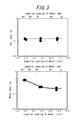
- FIG. 3 is a plot of the amount of wear of each of the rail material and the wheel material in the wear test against the pearlite lamellar spacing of the wheel material. As shown in the upper diagram of FIG. 3, the amount of wear of the rail material was almost constant regardless of the pearlite lamellar spacing of the wheel material. On the other hand, as shown in the lower diagram of FIG. 3, the wear amount of the wheel material was smaller as the pearlite lamellar spacing of the wheel material was smaller.
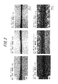
- the cross-sectional state of the rail material and wheel material after the wear test is shown in FIG.
- the pearlite lamellar spacing of the wheel material was 270 nm
- significant plastic flow was observed on the surface of the rail material.
- a wheel material with a lamellar spacing of 140 nm is used, and when a wheel material with a lamellar spacing of 90 nm is used, there is almost no surface plastic flow in both the wheel material and the rail material, and the lamellar spacing is 270 nm. Fatigue damage was suppressed compared to the case of.
- the microstructure in the region at least 15 mm deep from the tread surface is a pearlite structure, and the pearlite lamellar spacing in at least the region is 150 nm or less.
- C 0.65 to 0.84% C is an important element that forms cementite to increase hardness and strength and improve the wear resistance of the wheel material.
- the lower limit was made 0.65%.
- the amount of C is increased, cementite is increased and hardness is increased, but ductility and toughness are lowered, so that sufficient performance as a wheel for heavy cargo railway cannot be obtained.
- it exceeds 0.84% pro-eutectoid cementite comes to exist in the prior austenite grain boundaries, and the reduction of ductility and toughness becomes remarkable.
- the upper limit of the C content is set to 0.84% in the present invention. Preferably it is 0.70 to 0.84% of range.
- Si 0.1 to 1.5%
- Si is an element that decreases the pearlite lamellar spacing by increasing the pearlite equilibrium transformation temperature (T E ) and enhances the hardness and strength of the pearlite structure by solid solution strengthening of ferrite in the pearlite structure. Furthermore, Si reduces oxygen in steel as a deoxidizer. In order to acquire the said effect, 0.1% or more of addition is required. On the other hand, excessive addition promotes decarburization and promotes the formation of rail surface defects, so the upper limit of the Si content was set to 1.5%.
- the Si content is preferably 0.15 to 1.3%.
- Mn 0.05 to 1.5%
- Mn is an element having an effect of increasing the hardness of pearlite. Furthermore, Mn reduces oxygen in steel as a deoxidizer. In order to maintain high hardness up to the inside of the rail, 0.05% or more of Mn is added. On the other hand, addition exceeding 1.5% makes it easy to cause martensitic transformation harmful to rail wear and fatigue damage, so the upper limit of the Mn content is set to 1.5%.
- the Mn content is preferably 0.3 to 1.3%.
- P 0.025% or less P is segregated at the grain boundaries to reduce toughness and ductility. Therefore, the lower the mixing, the better. In the present invention, it is 0.025% or less. Further, there is no problem even if the lower limit is not particularly limited, but excessively low P leads to an increase in refining time and an increase in cost, so 0.001% or more is preferable.
- S 0.015% or less S forms coarse MnS that extends in the rolling direction and decreases ductility and toughness.
- the upper limit of the S content is set to 0.015%.
- it is 0.007% or less, more preferably 0.005% or less.
- the lower limit is not particularly specified, but excessively low S causes an increase in refining time and an increase in cost, so 0.0005% or more is preferable.
- Al 0.001 to 0.08% Al is added as a deoxidizer, but addition exceeding 0.08% tends to leave non-metallic inclusions (alumina clusters) in the steel and promotes fatigue damage. Therefore, the upper limit of the Al content is set to 0.08%. Preferably it is 0.05% or less. In order to exhibit the effect of Al as a deoxidizing material, it is preferable to add Al at 0.003% or more. However, depending on the conditions of refining and casting, it becomes difficult for the nonmetallic inclusions (alumina) to float on the slag, and when the alumina cannot be sufficiently removed, deoxidation with Si or Mn can be performed. In this case, Al may be less than 0.003%, and deoxidation with Al may not be performed. Moreover, it is difficult to make Al less than 0.001% with the assumed general-purpose refining technology. Therefore, the lower limit of the Al content is 0.001%.
- Cr 0.05 to 1.5% Cr contributes to refinement of the pearlite lamellar spacing by increasing T E and increases hardness and strength. Therefore, addition of 0.05% or more is required. On the other hand, if added over 1.5%, the occurrence of defects in the material increases and the hardenability increases, so that martensite that promotes rail damage is generated. Therefore, the upper limit of the Cr content is set to 1.5%. More preferably, it is in the range of 0.51 to 1.3%.
- the wheel material of the present invention further includes Cu: 0.03 to 0.5%, Ni: 0.03 to 0.5%, Mo: 0.00.
- Cu 0.03 to 0.5%
- Ni 0.03 to 0.5%
- Mo 0.00.
- Ti 0.002-0.02% as required Can be added.
- Cu 0.03-0.5%
- Ni 0.03-0.5%
- Ni is an element that improves toughness and ductility. Moreover, since Cu cracking can be suppressed by adding together with Cu, when adding Cu, it is preferable to add Ni simultaneously. Since these effects are not observed at less than 0.03%, the lower limit of the Ni content when adding Ni is set to 0.03% or more. On the other hand, addition exceeding 0.5% enhances hardenability and promotes the formation of martensite, so the upper limit of Ni content was set to 0.5%.
- Mo 0.02 to 0.2%
- Mo is an element effective for increasing the strength. Since the effect is small if it is less than 0.02%, when adding Mo, the Mo content is set to 0.02% or more. On the other hand, addition exceeding 0.2% increases the hardenability and promotes the formation of bainite and martensite, so the upper limit of the Mo content was set to 0.2%.
- V 0.003-0.3%
- V is an element that forms VC or VN and precipitates finely in ferrite and contributes to high strength through precipitation strengthening of ferrite. V also functions as a hydrogen trap site, and can be expected to suppress delayed fracture. In order to obtain these effects, 0.003% or more must be added. On the other hand, addition exceeding 0.3% saturates these effects and significantly increases the alloy cost, so the upper limit of V content was set to 0.3%. Preferably it is 0.005 to 0.12% of range.
- Nb 0.003 to 0.1% Nb forms NbC to Nb (C, N) and refines the pearlite colony and block size through the austenite refinement during the wheel heat treatment, which is effective in improving ductility and toughness. Further, Nb has the effect of suppressing delayed fracture in the same way as V. In order to obtain these effects, 0.003% or more must be added. On the other hand, addition exceeding 0.1% causes Nb carbonitride to crystallize during the solidification process and lowers cleanliness, so the upper limit of Nb content was set to 0.1%. Preferably, it is 0.005 to 0.05%.
- Ti 0.002 to 0.02%
- Ti forms TiC or TiN and, like Nb, refines pearlite colonies and block sizes through refinement of austenite during wheel heat treatment, which is effective in improving ductility and toughness.
- Ti is also effective in improving delayed fracture characteristics.
- addition of 0.002% or more is required.
- addition over 0.02% causes Ti carbonitrides to crystallize during the solidification process and lowers cleanliness, so the upper limit of Ti content was made 0.02%.
- the balance other than the above components is Fe and inevitable impurities.
- O forms oxides (mainly alumina clusters) and thus reduces rolling fatigue resistance. Therefore, it is desirable that the total oxygen amount be as small as possible, but the content can be allowed up to 0.004%. Preferably it is 0.002% or less.
- N forms a hard nitride such as AlN and lowers rolling fatigue damage resistance. Therefore, it is desirable that N be as small as possible, but its content is acceptable up to 0.005%. Preferably it is 0.004% or less.
- a microstructure in at least a region from the wheel tread surface to a depth of 15 mm is a pearlite structure, and a pearlite lamellar interval in at least the region is 150 nm or less.
- the microstructure of the entire tread surface is a pearlite in at least a tread part which is a part mainly in contact with the rail, specifically in a region from the tread to a depth of 15 mm. Since the wheel flange also comes into contact with the rail in the curve, it is preferable that the flange portion also has a pearlite structure.
- the pearlite lamellar spacing in the region from the wheel tread to at least 15 mm is set to 150 nm or less.
- the lamellar interval As described above, by setting the lamellar interval to 150 nm or less, it is possible to significantly reduce the amount of wear of the wheels and to suppress fatigue damage on the rail surface.
- the lamellar spacing of the wheel tread part that is in contact with the rail needs to be 150 nm or less, but considering the wear of the wheel during use, etc., at least 15 mm deeper than the tread.
- the pearlite lamellar spacing in the region was set to 150 nm or less.
- the lower limit of the lamellar interval is not particularly defined, there is a limit to the refinement of the pearlite structure, and 50 nm is the limit under conditions that can be manufactured as a wheel material.
- the average block size of pearlite from the wheel tread surface to at least 15 mm inside is 10 to 30 ⁇ m.
- Ductility and toughness are also important in order to prevent destruction from starting when fatigue damage or heat cracks occur in the wheel material during use of the wheel material. By setting the average block size of pearlite from the wheel tread to at least 15 mm inside to 30 ⁇ m or less, ductility and toughness are improved.
- pearlite is a layered structure (lamellar structure) made of soft ferrite and hard cementite, and a structural unit having the same orientation of ferrite is called a pearlite block.
- the inventors investigated the toughness of steel whose pearlite block size was changed by heat treatment. The result is shown in FIG.
- the toughness was evaluated by a Charpy impact test. Using Charpy impact test piece of 2mmU notch cut out from steel by machining, Charpy impact test was conducted at 20 ° C (room temperature), and the resulting Charpy absorbed energy uE 20 (J / cm 2 ) was used as an evaluation index for toughness (Charpy impact value).
- the pearlite block size was measured by EBSP (Electron Back Scattering Pattern) method.
- the orientation of ferrite in a 0.25 ⁇ 0.25 mm size region was measured by EBSP, the block interface was traced, and the average block size was determined by image processing. In the measurement, the boundary where the electron beam size was 0.3 ⁇ m and the orientation difference of ferrite was 15 ° or more was defined as the block interface.
- FIG. 5 shows that the toughness is extremely improved when the average block size is more than 30 ⁇ m, but the toughness is low when the average block size is 30 ⁇ m or less. Therefore, the average block size of pearlite is preferably 30 ⁇ m or less. More preferably, it is 25 ⁇ m or less. Although there is no particular lower limit of the preferred block size, it is industrially difficult to make the block size less than 10 ⁇ m under general-purpose manufacturing conditions, and the block size is practically 10 ⁇ m or more.
- 0.2% YS 0.2% proof stress
- the yield ratio is 60% or more in the inside of 15 mm from the tread.
- 0.2% YS is less than 700 MPa and the yield ratio is less than 60%, the wheel surface is liable to be damaged, and the affected rail is also affected.
- the upper limit is not particularly specified, it is preferable that 0.2% YS is 1100 MPa or less and the yield ratio is 85% or less in consideration of the manufacturing process.
- the elongation within 15 mm from the tread is 12% or more and the Charpy impact value at 20 ° C. is 15 J or more from the viewpoint of preventing fatigue damage from wheel treads and heat cracks. If the elongation of the tread portion is less than 12%, it is insufficient for destruction due to surface damage during use. The elongation of the tread portion is more preferably 14% or more. Further, the Charpy impact value at 20 ° C. of the tread part is preferably 15 J or more. If the Charpy impact value at 20 ° C. is less than 15 J, the risk of breakage from fatigue damage increases during use. The Charpy impact value at 20 ° C. of the tread surface is more preferably 20 J or more.
- the railway wheel according to the present invention is a hot rolling process and / or a hot rolling process for a material in which steel that has been melted, degassed, and alloy-adjusted in an electric furnace or top blow converter is made into a bloom by ingot or continuous casting. It can be manufactured by forming into a wheel shape through an intermediate forging process and then performing a heat treatment. The material is reheated when performing hot rolling and / or hot forging. The heating temperature at this time is preferably 1200 to 1350 ° C.
- the heating temperature is less than 1200 ° C.
- the processing temperature at the time of forming into a wheel shape by hot forging or hot rolling becomes low, the forming load increases and the formability decreases.
- the heating temperature exceeds 1350 ° C., internal defects increase, so the heating temperature is preferably 1350 ° C. or lower.
- the heating temperature for this heat treatment is Ac 3 point + 50 ° C. or higher.
- the heating temperature is less than Ac 3 point + 50 ° C., sufficient strength cannot be obtained.
- the heating temperature during the heat treatment exceeds the Ac 3 point + 150 ° C., the pearlite block size becomes coarse, and the toughness and ductility are lowered. Therefore, the heating temperature during the heat treatment is set to Ac 3 point + 150 ° C. or lower. It is preferable.
- Accelerated cooling is performed following the heat treatment heating step.
- it is necessary to set the cooling start temperature to 700 ° C. or higher, the cooling rate to 1 to 10 ° C./s, and the cooling stop temperature to 500 to 650 ° C.
- the cooling start temperature is less than 700 ° C., the pearlite lamellar spacing becomes coarse, and sufficient strength cannot be secured, resulting in a decrease in wear resistance.
- it is 730 ° C or more.
- blast cooling, water / air mixed jet cooling, or the like can be used, but the cooling rate of the surface corresponding to the tread surface is in the range of 1 to 10 ° C./s.
- the cooling rate When the cooling rate is less than 1 ° C./s, the pearlite lamellar spacing exceeds 150 nm. On the other hand, when the cooling rate is over 10 ° C./s, bainite and martensite are generated. A more preferable cooling rate range is 2 to 7 ° C./s.
- the cooling stop temperature must be 500 to 650 ° C. When the cooling stop temperature exceeds 650 ° C., the cooling is stopped before the pearlite transformation is sufficiently completed, and the pearlite lamellar interval is widened. When accelerated cooling to below 500 ° C., a bainite structure and a martensite structure are generated. It is desirable to air-cool the wheels after the accelerated cooling is completed. Furthermore, although cooling may be started directly after completion of forging and / or hot rolling, the cooling start temperature needs to be 700 ° C or higher, preferably 730 ° C or higher.
- stress relief annealing may be performed as necessary.
- finish cutting is performed on the wheel so as to have a predetermined shape.
- the microstructure of the wheel material in the region from the tread surface to a depth of 15 mm was determined by corroding the wheel material with a nital solution and observing under a microscope.
- the lamellar spacing and the pearlite block size in the region were measured by the method described above.
- the 0.2% YS, tensile tension, yield ratio, and elongation within 15 mm from the tread surface of the wheel material were measured by a tensile test at room temperature.
- a tensile test AREMA round bar tensile specimens having a distance between grades (GL) of 50 mm and a diameter of 12.5 mm collected from the wheel material were used.
- a 2 mm U-notch Charpy impact test piece was cut out by machining. The Charpy impact test was performed at 20 ° C. (room temperature) to determine the Charpy absorbed energy.
- the performance of the wheel material was evaluated based on the amount of wear and the occurrence of surface damage in the wear test.
- the wear test method and its conditions are as described above.
- the cross section of the test piece after the abrasion test was mirror-polished, and the surface crack was found to be “existing” when the microscopic observation was made, and the surface crack was found to be “no”.
- 0.82% C-0.55% Si-0.55% Mn-0.78% Cr-V rail steel was used as 0.82% C-0.55% Si-0.55% Mn-0.78% Cr-V rail steel was used.
- the microstructure of the rail material was pearlite, and the hardness was HB400.
- Table 4 shows the microstructure observation results
- Table 5 shows the results of various tests.
- the wear amount of the wheel itself is small and surface cracks are not observed. No surface damage was observed.
- the total amount of wear including the amount of wear of the rail and the wheel is large, and surface cracks of the rail were observed.
- the wheel materials of test numbers 4, 5, 6, and 7 have a microstructure of pearlite but a lamellar spacing of 150 nm or more.
- the amount of wear of the rail material was slightly small, the amount of wear of the wheel material was large, and as a result, the total amount of wear was large.
- test number 14 using a wheel material having a low C content the surface crack of the wheel material occurred and the wear amount was high even though the pearlite lamellar spacing satisfied the conditions of the present invention.
- surface cracking was observed in test number 15 using a wheel material having a high C content. It can be seen that because the C content is high, the ductility (elongation) and toughness are low, and the damage resistance is low.
- the wheels of the test numbers 1, 8 to 13, 18, and 20 in which the pearlite block size is 30 ⁇ m or less have higher elongation and toughness than the wheel material of the test number 22 in which the pearlite block size exceeds 30 ⁇ m. It was.
- the total wear amount of the wheel material and rail material is reduced, and both the wheel and rail are reduced. It was possible to suppress the occurrence of surface damage. As a result, not only the wheel but also the service life of the rail can be dramatically improved.
- by further finely controlling the pearlite block size ductility and toughness can be further improved, and a railway wheel having excellent wear resistance and damage resistance can be obtained.
- the railway vehicle wheel of the present invention having such excellent characteristics is particularly useful as a wheel used in a harsh environment such as a heavy cargo railway.
Landscapes
- Chemical & Material Sciences (AREA)
- Engineering & Computer Science (AREA)
- Mechanical Engineering (AREA)
- Materials Engineering (AREA)
- Metallurgy (AREA)
- Organic Chemistry (AREA)
- Physics & Mathematics (AREA)
- Thermal Sciences (AREA)
- Crystallography & Structural Chemistry (AREA)
- Heat Treatment Of Steel (AREA)
- Heat Treatment Of Articles (AREA)
Abstract
Description
(1)高軸重用途で近年利用されているパーライトレールを相手材とした場合、車輪踏面のミクロ組織がパーライトである場合の方が、特許文献1などで採用されているベイナイトや焼戻しマルテンサイトである場合よりも車輪とレールのトータルでの摩耗や疲労損傷を抑制できる。
(2)踏面のミクロ組織がパーライトである車輪の中でも、少なくとも踏面より深さ15mm内部までの領域におけるパーライトラメラー間隔を150nm以下としたものを用いることにより、さらに車輪とレールの摩耗や疲労損傷を抑制できる。
(3)上記(2)のパーライトラメラー間隔を150nm以下とした車輪において、車輪材の化学組成を最適化し、特に、Cを0.65~0.84質量%とすることにより耐摩耗性と延性および靱性とを両立できる。
(4)さらに、延性や靭性を確保するためには、必要に応じてパーライト組織のブロックサイズは30μm以下とすることが有効である。
質量パーセントで、C:0.65~0.84%、Si:0.1~1.5%、Mn:0.05~1.5%、P:0.025%以下、S:0.015%以下、Al:0.001~0.08%、およびCr:0.05~1.5%を有し、残部がFeおよび不可避的不純物であり、少なくとも踏面より深さ15mm内部までの領域におけるミクロ組織がパーライト組織であり、少なくとも前記領域におけるパーライトラメラー間隔が150nm以下である鉄道車両用車輪。
以上の構成を採ることにより、本発明では車輪とレールのトータルでの耐摩耗性、耐表面損傷性を向上させることができる。
次に、本発明を具体的に説明する。
まず、発明者らは、車輪踏面のミクロ組織の種類が車輪とレールの摩耗及び表面損傷に与える影響を明らかにするために、パーライト、ベイナイト、および焼もどしマルテンサイトの3種類のミクロ組織からなる車輪材を用意し、それぞれについて同一のレール材との組み合わせで摩耗試験を行った。前記摩耗試験には図1に示した二円筒式の摩耗試験機を使用し、一方の試験片として車輪踏面を模擬した車輪材試験片を、他方の試験片としてレールを模擬したレール材試験片を、それぞれ用いた。


次に、パーライト組織の車輪を使用した場合に、該パーライト組織のラメラー間隔が車輪材とレール材、両者の摩耗と表面損傷に及ぼす影響について検討した。
まず、本発明において、車輪材の成分組成を前記の範囲に限定した理由について説明する。なお、成分に関する「%」表示は、特に断らない限り「質量%」を意味するものとする。
Cはセメンタイトを形成して硬さや強度を高め、車輪材の耐摩耗性を向上させる重要な元素である。しかし、0.65%未満ではそれらの効果が小さいことから下限を0.65%とした。しかし、C量を増加させるとセメンタイトが増加して硬度が増すが、延性や靭性が低下するため、重貨物鉄道用の車輪として十分な性能が得られない。特に、0.84%を超えると、初析セメンタイトが旧オーステナイト粒界に存在するようになり、延性や靱性の低下が顕著となる。これらを考慮して本発明ではC含有量の上限を0.84%とした。好ましくは0.70~0.84%の範囲である。
Siはパーライト平衡変態温度(TE)を上昇させることによってパーライトラメラー間隔を減少させるとともに、パーライト組織中のフェライトを固溶強化して、パーライト組織の硬さや強度を上昇させる元素である。さらに、Siは脱酸材として鋼中の酸素を低減させる。前記効果を得るために0.1%以上の添加が必要である。一方、過剰の添加は脱炭を促進し、レールの表面庇の生成を促進させることから、Si含有量の上限を1.5%とした。Si含有量は0.15~1.3%とすることが好ましい。
Mnはパーライトの硬さを上昇させる効果を有する元素である。さらに、Mnは脱酸材として鋼中の酸素を低減させる。レール内部まで高硬度を維持するために、Mnを0.05%以上添加することとする。一方、1.5%を超えての添加は、レールの摩耗や疲労損傷に対して有害なマルテンサイト変態をおこしやすくするため、Mn含有量の上限を1.5%とした。Mn含有量は0.3~1.3%とすることが好ましい。
Pは結晶粒界に偏析して靭性や延性を低下させるため、その混入は低いほど望ましく、本発明では0.025%以下とする。また、下限については特に限定せずとも問題はないが、過度の低P化は精錬時間の増加やコストの上昇を招くため、0.001%以上とすることが好ましい。
Sは圧延方向に伸展した粗大なMnSを形成して、延性や靭性を低下させる。特に、高軸重環境にさらされる車輪の場合には延性の低下は顕著となる。そのため、Sの含有量の上限は0.015%とした。好ましくは、0.007%以下、さらに好ましくは0.005%以下である。一方、下限については特に規定しないが、過度の低S化は精錬時間の増加やコストの上昇を招くため、0.0005%以上とすることが好ましい。
Alは脱酸材として添加するが、0.08%を超えての添加は鋼中に非金属介在物(アルミナクラスター)が残存しやすくなり、疲労損傷を促進させる。そこで、Al含有量の上限は0.08%とした。好ましくは0.05%以下である。Alの脱酸材としての作用を発現させるには、0.003%以上でAlを添加することが好ましい。しかし、精錬や鋳込みの条件によって、非金属介在物(アルミナ)のスラグへの浮上が困難となり、アルミナが十分に除去できない場合には、SiやMnによる脱酸を行うことも可能である。この場合は、Alは0.003%未満であってもかまわず、Alによる脱酸を行わないこともできる。また、Alを0.001%未満とすることは、想定している汎用の精錬技術では困難である。よって、Al含有量の下限は0.001%とする。
Crは、TEを上昇させることによってパーライトラメラー間隔の微細化に寄与し、硬さ
や強度を上昇させる。そのため、0.05%以上の添加を必要とする。一方、1.5%を超えて添加すると、素材の欠陥発生が増加するとともに、焼入れ性が増加するためレール損傷を促進させるマルテンサイトが生成する。そこで、Cr含有量の上限を1.5%とした。より好ましくは、0.51~1.3%の範囲である。
Cuを添加することによって、固溶強化による一層の高硬度化を図ることができる。この効果を得るためには0.03%以上の添加が必要である。一方、0.5%を超えての添加は連続鋳造時や圧延時に表面割れを生じ易くすることから、Cu含有量の上限は0.5%とする。
Niは靭性や延性を向上させる元素である。また、Cuと複合添加することでCu割れを抑制することができるため、Cuを添加する場合には同時にNiを添加することが好ましい。0.03%未満ではこれら効果が認められないことから、Niを添加する場合におけるNi含有量の下限を0.03%以上とした。一方、0.5%を超えての添加は、焼入れ性を高め、マルテンサイトの生成を促進させるので、Ni含有量の上限を0.5%とした。
Moは高強度化に有効な元素である。0.02%未満ではその効果が小さいので、Moを添加する場合には、Mo含有量を0.02%以上とする。一方、0.2%を超えての添加は焼入れ牲を高め、ベイナイトやマルテンサイトの生成を促進するので、Mo含有量の上限は0.2%とした。
Vは、VCあるいはVNなどを形成してフェライト中へ微細に析出し、フェライトの析出強化を通して高強度化に寄与する元素である。また、Vは水素のトラップサイトとしても機能し、遅れ破壊を抑制する効果も期待できる。これらの効果を得るために、0.003%以上の添加を必要とする。一方、0.3%を超えての添加はそれらの効果が飽和し合金コストの上昇も甚だしいので、V含有量の上限を0.3%とした。好ましくは0.005~0.12%の範囲である。
Nbは、NbCないしNb(C,N)を形成し、車輪熱処理時のオーステナイト微細化を通してパーライトコロニーやブロックサイズを微細化させるため、延性や靭性の向上に有効である。また、Nbは、Vと同様に遅れ破壊を抑制する効果を有する。これらの効果を得るためには、0.003%以上の添加を必要とする。一方、0.1%を超えての添加は、凝固過程でNb炭窒化物を晶出させ、清浄性を低下させるので、Nb含有量の上限を0.1%とした。好ましくは、0.005~0.05%である。
Tiは、TiCないしTiNを形成し、Nbと同様に車輪熱処理時のオーステナイト微細化を通してパーライトコロニーやブロックサイズを微細化するため、延性や靭性向上に有効である。また、Tiは、遅れ破壊特性向上にも有効である。これらの効果を得るためには、0.002%以上の添加を必要とする。一方、0.02%を超えての添加は、凝固過程でTi炭窒化物を晶出させ、清浄性を低下させるので、Ti含有量の上限を0.02%とした。
本発明の車輪では、踏面から15mm内部における、0.2%YSを700MPa以上、降伏比を60%以上とすることが好ましい。これにより、車輪とレールの表面損傷を抑制することができる。0.2%YSが700MPa未満、降伏比60%未満では、車輪の表面損傷が生じやすくなり、接触するレールにもその影響が及ぶためである。上限については特に規定しないが、製造工程を考慮すると0.2%YSを1100MPa以下、降伏比を85%以下とすることが好ましい。
本発明の鉄道用車輪は、電気炉や上吹き転炉などで溶製、脱ガス処理、合金調整をした鋼をインゴットや連続鋳造によりブルームとした素材に対し、熱間圧延工程および/または熱間鍛造工程を経て車輪形状へ成形し、その後、熱処理を施すことによって製造できる。
熱間圧延および/または熱間鍛造を行うにあたって素材を再加熱する。この際の加熱温度は、1200~1350℃が好ましい。加熱温度が1200℃未満では、熱間鍛造や熱間圧延で車輪形状へ成形する際の加工温度が低温となり、成形荷重が増大して成形性が低下する。一方、加熱温度が1350℃を超えると内部欠陥が増加するので、加熱温度は1350℃以下とすることが好ましい。
表3に示した種々の成分組成の鋼を素材として、表4に示す圧延前加熱温度で加熱した後、熱間圧延を施して車輪を模擬した板材(以下、車輪材とも云う)に成形した。車輪形状に成形した素材を、表4に示す条件で熱処理を施し車輪材を得た。得られた車輪材を試料として、ミクロ組織の観察、引張試験、シャルピー衝撃試験および摩耗試験を実施した。使用した車輪材およびレール材は常用の製造工程を模擬してシミュレーションで再現させ、ラボで製造した。
シャルピー衝撃試験片は、2mmUノッチのシャルピー衝撃試験片を機械加工により切り出した。シャルピー衝撃試験は20℃(室温)で行い、シャルピー吸収エネルギーを求めた。


Claims (8)
- 質量パーセントで、C:0.65~0.84%、Si:0.1~1.5%、Mn:0.05~1.5%、P:0.025%以下、S:0.015%以下、Al:0.001~0.08%、およびCr:0.05~1.5%を有し、残部がFeおよび不可避的不純物であり、少なくとも踏面より深さ15mm内部までの領域におけるミクロ組織がパーライト組織であり、少なくとも前記領域におけるパーライトラメラー間隔が150nm以下である鉄道車両用車輪。
- 請求項1に記載の鉄道車両用車輪であって、
さらに、質量パーセントで、Cu:0.03~0.5%、Ni:0.03~0.5%、Mo:0.02~0.2%、V:0.003~0.3%、Nb:0.003~0.1%、およびTi:0.002~0.02%から選ばれる1種または2種以上を含有する鉄道車両用車輪。 - 請求項1または2に記載の鉄道車両用車輪であって、前記領域における平均パーライトブロックサイズが30μm以下である鉄道車両用車輪。
- 請求項1乃至3のいずれか一項に記載の鉄道車両用車輪であって、踏面から15mm内部での、0.2%耐力(YS)が700MPa以上、降伏比が60%以上である鉄道車両用車輪。
- 請求項3に記載の鉄道車両用車輪であって、踏面から15mm内部での、0.2%耐力(YS)が700MPa以上、降伏比が60%以上、伸びが12%以上、20℃におけるシャルピー衝撃値が15J以上である鉄道車両用車輪。
- 質量パーセントで、C:0.65~0.84%、Si:0.1~1.5%、Mn:0.05~1.5%、P:0.025%以下、S:0.015%以下、Al0.001~0.08%、およびCr:0.05~1.5%を有し、残部がFeおよび不可避的不純物である鋼を、電気炉あるいは転炉で溶製し、鋳造して素材とし、該素材を熱間圧延および/または熱間鍛造を行い成形した後、該成形された車輪を加熱温度Ac3点+50℃以上に加熱し、冷却開始温度:700℃以上、冷却速度:1~10℃/s、冷却停止温度:500~650℃の加速冷却を行った後、空冷する鉄道車両用車輪の製造方法。
- 請求項6に記載の鉄道車両用車輪の製造方法であって、
前記鋼は、さらに、質量パーセントで、Cu:0.03~0.5%、Ni:0.03~0.5%、Mo:0.02~0.2%、V:0.003~0.3%、Nb:0.003~0.1%、およびTi:0.002~0.02%から選ばれる1種または2種以上を含有する鉄道車両用車輪の製造方法。 - 請求項6または7に記載の鉄道車両用車輪の製造方法であって、
前記加熱温度はAc3点+150℃以下である鉄道車両用車輪の製造方法。
Priority Applications (7)
| Application Number | Priority Date | Filing Date | Title |
|---|---|---|---|
| JP2016527637A JP6210155B2 (ja) | 2014-06-11 | 2015-06-09 | 鉄道車両用車輪および鉄道車両用車輪の製造方法 |
| AU2015272889A AU2015272889B2 (en) | 2014-06-11 | 2015-06-09 | Wheel for railroad car and method for manufacturing wheel for railroad car |
| BR112016028776A BR112016028776A2 (pt) | 2014-06-11 | 2015-06-09 | roda para veículo ferroviário e método de fabricação de roda para veículo ferroviário |
| CN201580027162.7A CN106460117A (zh) | 2014-06-11 | 2015-06-09 | 铁路车辆用车轮及铁路车辆用车轮的制造方法 |
| US15/313,186 US20170191149A1 (en) | 2014-06-11 | 2015-06-09 | Railway vehicle wheel and method for manufacturing railway vehicle wheel |
| CA2948297A CA2948297C (en) | 2014-06-11 | 2015-06-09 | Railway vehicle wheel and method for manufacturing railway vehicle wheel |
| US16/517,684 US20190338402A1 (en) | 2014-06-11 | 2019-07-22 | Method for manufacturing railway vehicle wheel |
Applications Claiming Priority (2)
| Application Number | Priority Date | Filing Date | Title |
|---|---|---|---|
| JP2014120542 | 2014-06-11 | ||
| JP2014-120542 | 2014-06-11 |
Related Child Applications (2)
| Application Number | Title | Priority Date | Filing Date |
|---|---|---|---|
| US15/313,186 A-371-Of-International US20170191149A1 (en) | 2014-06-11 | 2015-06-09 | Railway vehicle wheel and method for manufacturing railway vehicle wheel |
| US16/517,684 Division US20190338402A1 (en) | 2014-06-11 | 2019-07-22 | Method for manufacturing railway vehicle wheel |
Publications (1)
| Publication Number | Publication Date |
|---|---|
| WO2015190088A1 true WO2015190088A1 (ja) | 2015-12-17 |
Family
ID=54833200
Family Applications (1)
| Application Number | Title | Priority Date | Filing Date |
|---|---|---|---|
| PCT/JP2015/002886 Ceased WO2015190088A1 (ja) | 2014-06-11 | 2015-06-09 | 鉄道車両用車輪および鉄道車両用車輪の製造方法 |
Country Status (7)
| Country | Link |
|---|---|
| US (2) | US20170191149A1 (ja) |
| JP (1) | JP6210155B2 (ja) |
| CN (1) | CN106460117A (ja) |
| AU (1) | AU2015272889B2 (ja) |
| BR (1) | BR112016028776A2 (ja) |
| CA (1) | CA2948297C (ja) |
| WO (1) | WO2015190088A1 (ja) |
Cited By (10)
| Publication number | Priority date | Publication date | Assignee | Title |
|---|---|---|---|---|
| CN106521315A (zh) * | 2016-11-10 | 2017-03-22 | 钢铁研究总院 | 一种高强度高韧性重载列车车轮用钢及其热处理方法 |
| WO2017150545A1 (ja) * | 2016-03-02 | 2017-09-08 | 新日鐵住金株式会社 | 鉄道用車輪 |
| WO2018181862A1 (ja) * | 2017-03-31 | 2018-10-04 | 新日鐵住金株式会社 | 鉄道車輪の製造方法及び鉄道車輪 |
| WO2018181861A1 (ja) * | 2017-03-31 | 2018-10-04 | 新日鐵住金株式会社 | 鉄道車輪 |
| WO2020067520A1 (ja) * | 2018-09-28 | 2020-04-02 | 日本製鉄株式会社 | 鉄道車輪 |
| WO2020067506A1 (ja) * | 2018-09-28 | 2020-04-02 | 日本製鉄株式会社 | 鉄道車輪 |
| WO2021193808A1 (ja) * | 2020-03-26 | 2021-09-30 | 日本製鉄株式会社 | 鉄道車輪 |
| EA039774B1 (ru) * | 2018-01-31 | 2022-03-11 | Ниппон Стил Корпорейшн | Железнодорожное колесо |
| JPWO2022220237A1 (ja) * | 2021-04-16 | 2022-10-20 | ||
| JP2023551416A (ja) * | 2020-11-17 | 2023-12-08 | アルセロールミタル | レール用鋼及びそのレールの製造方法 |
Families Citing this family (14)
| Publication number | Priority date | Publication date | Assignee | Title |
|---|---|---|---|---|
| JP6555447B2 (ja) * | 2017-03-21 | 2019-08-07 | Jfeスチール株式会社 | レールの製造方法 |
| CN108998727A (zh) * | 2018-07-27 | 2018-12-14 | 江苏沙钢集团淮钢特钢股份有限公司 | 一种强耐磨、耐冲击的铌钛微合金化高碳合金钢及其生产方法 |
| CN109355577B (zh) * | 2018-12-14 | 2022-01-28 | 辽宁衡业高科新材股份有限公司 | 一种1200MPa级别热处理车轮的制备方法 |
| US12534772B2 (en) * | 2019-03-06 | 2026-01-27 | Nippon Steel Corporation | Hot rolled steel sheet and method for producing same |
| KR20220146419A (ko) | 2020-03-02 | 2022-11-01 | 닛폰세이테츠 가부시키가이샤 | 열간 압연 강판 |
| CN111961963A (zh) * | 2020-07-28 | 2020-11-20 | 马鞍山钢铁股份有限公司 | 一种中碳的铌钒微合金化高速车轮钢及车轮制备方法 |
| CN111996444B (zh) * | 2020-07-28 | 2021-12-14 | 马鞍山钢铁股份有限公司 | 一种中碳中硅的铌微合金化高速车轮钢及车轮制备方法 |
| CN112251667B (zh) * | 2020-09-28 | 2022-05-24 | 宝武集团马钢轨交材料科技有限公司 | 一种提高硬度均匀性和降低异常组织深度的城市轨道用中碳车轮钢 |
| US20240399789A1 (en) * | 2021-10-14 | 2024-12-05 | Nippon Steel Corporation | Railway wheel |
| CN114574672B (zh) * | 2022-03-30 | 2023-06-27 | 马鞍山钢铁股份有限公司 | 一种高效经济型铁路车轮热加工方法及铁路车轮 |
| CN114645115B (zh) * | 2022-04-25 | 2023-06-27 | 马鞍山钢铁股份有限公司 | 一种硬度等级在360hb以上的重载货车用车轮及其热处理方法和生产方法 |
| CN115679217B (zh) * | 2022-11-11 | 2024-02-13 | 山东钢铁股份有限公司 | 一种起重机轮体用高碳钢及其制备方法 |
| CN115896632B (zh) * | 2022-12-09 | 2024-01-30 | 宝武集团马钢轨交材料科技有限公司 | 一种耐蚀抗磨车轮及其生产方法 |
| CN116590593A (zh) * | 2023-04-13 | 2023-08-15 | 攀钢集团攀枝花钢铁研究院有限公司 | 一种高耐蚀性和高耐磨性的珠光体钢轨及其制备方法 |
Citations (6)
| Publication number | Priority date | Publication date | Assignee | Title |
|---|---|---|---|---|
| JPS516812A (ja) * | 1974-05-24 | 1976-01-20 | Krupp Ag Huettenwerke | |
| JPS57143469A (en) * | 1981-02-27 | 1982-09-04 | Sumitomo Metal Ind Ltd | Steel for railroad wheel with superior wear resistance |
| JPH09202937A (ja) * | 1996-01-23 | 1997-08-05 | Sumitomo Metal Ind Ltd | 耐摩耗性および耐熱亀裂性に優れた鉄道車両用車輪およびその製造方法 |
| JP2004315928A (ja) * | 2003-04-18 | 2004-11-11 | Nippon Steel Corp | 耐摩耗性および耐熱き裂性に優れた高炭素鉄道車両用車輪 |
| JP2012107295A (ja) * | 2010-11-18 | 2012-06-07 | Sumitomo Metal Ind Ltd | 車輪用鋼 |
| JP2013231212A (ja) * | 2012-04-27 | 2013-11-14 | Nippon Steel & Sumitomo Metal Corp | 車輪用鋼 |
Family Cites Families (9)
| Publication number | Priority date | Publication date | Assignee | Title |
|---|---|---|---|---|
| US3846183A (en) * | 1973-05-02 | 1974-11-05 | Bethlehem Steel Corp | Method of treating steel rail |
| JPH08109440A (ja) * | 1994-10-07 | 1996-04-30 | Nippon Steel Corp | パーライト金属組織を呈した高靭性レール |
| US6361625B2 (en) * | 1996-07-04 | 2002-03-26 | Nkk Corporation | High-strength, damage-resistant rail having hardness distribution of excellent damage-resistance at its head top portion |
| JP2002363701A (ja) * | 2001-06-12 | 2002-12-18 | Nkk Corp | パーライト系レール |
| CN100443617C (zh) * | 2005-12-29 | 2008-12-17 | 攀枝花钢铁(集团)公司 | 珠光体类热处理钢轨及其生产方法 |
| US20090053095A1 (en) * | 2007-08-23 | 2009-02-26 | Transportation Technology Center, Inc. | Railroad steels having improved resistance to rolling contact fatigue |
| JP5292875B2 (ja) * | 2007-10-10 | 2013-09-18 | Jfeスチール株式会社 | 耐摩耗性,耐疲労損傷性および耐遅れ破壊性に優れた内部高硬度型パーライト鋼レールおよびその製造方法 |
| JP5776565B2 (ja) * | 2012-01-23 | 2015-09-09 | 新日鐵住金株式会社 | レール鋼及び車輪鋼の材質選択方法 |
| CN103160754B (zh) * | 2013-03-05 | 2015-05-06 | 大同爱碧玺铸造有限公司 | 一种微合金钢铸钢车轮及其制造方法 |
-
2015
- 2015-06-09 CN CN201580027162.7A patent/CN106460117A/zh active Pending
- 2015-06-09 US US15/313,186 patent/US20170191149A1/en not_active Abandoned
- 2015-06-09 WO PCT/JP2015/002886 patent/WO2015190088A1/ja not_active Ceased
- 2015-06-09 JP JP2016527637A patent/JP6210155B2/ja active Active
- 2015-06-09 AU AU2015272889A patent/AU2015272889B2/en active Active
- 2015-06-09 BR BR112016028776A patent/BR112016028776A2/pt not_active Application Discontinuation
- 2015-06-09 CA CA2948297A patent/CA2948297C/en active Active
-
2019
- 2019-07-22 US US16/517,684 patent/US20190338402A1/en not_active Abandoned
Patent Citations (6)
| Publication number | Priority date | Publication date | Assignee | Title |
|---|---|---|---|---|
| JPS516812A (ja) * | 1974-05-24 | 1976-01-20 | Krupp Ag Huettenwerke | |
| JPS57143469A (en) * | 1981-02-27 | 1982-09-04 | Sumitomo Metal Ind Ltd | Steel for railroad wheel with superior wear resistance |
| JPH09202937A (ja) * | 1996-01-23 | 1997-08-05 | Sumitomo Metal Ind Ltd | 耐摩耗性および耐熱亀裂性に優れた鉄道車両用車輪およびその製造方法 |
| JP2004315928A (ja) * | 2003-04-18 | 2004-11-11 | Nippon Steel Corp | 耐摩耗性および耐熱き裂性に優れた高炭素鉄道車両用車輪 |
| JP2012107295A (ja) * | 2010-11-18 | 2012-06-07 | Sumitomo Metal Ind Ltd | 車輪用鋼 |
| JP2013231212A (ja) * | 2012-04-27 | 2013-11-14 | Nippon Steel & Sumitomo Metal Corp | 車輪用鋼 |
Cited By (23)
| Publication number | Priority date | Publication date | Assignee | Title |
|---|---|---|---|---|
| WO2017150545A1 (ja) * | 2016-03-02 | 2017-09-08 | 新日鐵住金株式会社 | 鉄道用車輪 |
| EA035081B9 (ru) * | 2016-03-02 | 2020-07-09 | Ниппон Стил Корпорейшн | Железнодорожное колесо |
| EA035081B1 (ru) * | 2016-03-02 | 2020-04-24 | Ниппон Стил Корпорейшн | Железнодорожное колесо |
| JPWO2017150545A1 (ja) * | 2016-03-02 | 2018-12-20 | 新日鐵住金株式会社 | 鉄道用車輪 |
| CN106521315A (zh) * | 2016-11-10 | 2017-03-22 | 钢铁研究总院 | 一种高强度高韧性重载列车车轮用钢及其热处理方法 |
| JP6443606B1 (ja) * | 2017-03-31 | 2018-12-26 | 新日鐵住金株式会社 | 鉄道車輪 |
| WO2018181861A1 (ja) * | 2017-03-31 | 2018-10-04 | 新日鐵住金株式会社 | 鉄道車輪 |
| WO2018181862A1 (ja) * | 2017-03-31 | 2018-10-04 | 新日鐵住金株式会社 | 鉄道車輪の製造方法及び鉄道車輪 |
| EP3604599A4 (en) * | 2017-03-31 | 2020-12-30 | Nippon Steel Corporation | RAILWAY WHEEL |
| JPWO2018181862A1 (ja) * | 2017-03-31 | 2019-04-11 | 新日鐵住金株式会社 | 鉄道車輪の製造方法及び鉄道車輪 |
| EA039774B1 (ru) * | 2018-01-31 | 2022-03-11 | Ниппон Стил Корпорейшн | Железнодорожное колесо |
| WO2020067520A1 (ja) * | 2018-09-28 | 2020-04-02 | 日本製鉄株式会社 | 鉄道車輪 |
| WO2020067506A1 (ja) * | 2018-09-28 | 2020-04-02 | 日本製鉄株式会社 | 鉄道車輪 |
| JP6737427B1 (ja) * | 2018-09-28 | 2020-08-12 | 日本製鉄株式会社 | 鉄道車輪 |
| JPWO2020067520A1 (ja) * | 2018-09-28 | 2021-02-15 | 日本製鉄株式会社 | 鉄道車輪 |
| WO2021193808A1 (ja) * | 2020-03-26 | 2021-09-30 | 日本製鉄株式会社 | 鉄道車輪 |
| JP7031793B2 (ja) | 2020-03-26 | 2022-03-08 | 日本製鉄株式会社 | 鉄道車輪 |
| JPWO2021193808A1 (ja) * | 2020-03-26 | 2021-09-30 | ||
| AU2021243639B2 (en) * | 2020-03-26 | 2023-11-02 | Nippon Steel Corporation | Railway wheel |
| JP2023551416A (ja) * | 2020-11-17 | 2023-12-08 | アルセロールミタル | レール用鋼及びそのレールの製造方法 |
| JPWO2022220237A1 (ja) * | 2021-04-16 | 2022-10-20 | ||
| WO2022220237A1 (ja) | 2021-04-16 | 2022-10-20 | 日本製鉄株式会社 | 鉄道車輪 |
| JP7667492B2 (ja) | 2021-04-16 | 2025-04-23 | 日本製鉄株式会社 | 鉄道車輪 |
Also Published As
| Publication number | Publication date |
|---|---|
| CA2948297C (en) | 2019-08-20 |
| CN106460117A (zh) | 2017-02-22 |
| US20190338402A1 (en) | 2019-11-07 |
| JP6210155B2 (ja) | 2017-10-11 |
| AU2015272889B2 (en) | 2018-06-21 |
| CA2948297A1 (en) | 2015-12-17 |
| JPWO2015190088A1 (ja) | 2017-04-20 |
| BR112016028776A2 (pt) | 2017-08-22 |
| AU2015272889A1 (en) | 2016-11-10 |
| US20170191149A1 (en) | 2017-07-06 |
Similar Documents
| Publication | Publication Date | Title |
|---|---|---|
| JP6210155B2 (ja) | 鉄道車両用車輪および鉄道車両用車輪の製造方法 | |
| JP4390004B2 (ja) | 耐摩耗性と耐疲労損傷性に優れた内部高硬度型パーライト鋼レールおよびその製造方法 | |
| JP5292875B2 (ja) | 耐摩耗性,耐疲労損傷性および耐遅れ破壊性に優れた内部高硬度型パーライト鋼レールおよびその製造方法 | |
| JP5494433B2 (ja) | 車輪用鋼 | |
| KR102772505B1 (ko) | 내피로 균열 전파 특성이 우수한 레일 및 그 제조 방법 | |
| CN114402086B (zh) | 耐磨损钢板及其制造方法 | |
| EP2843071B1 (en) | Steel for railway wheel | |
| JP5282506B2 (ja) | 耐摩耗性と耐疲労損傷性に優れた内部高硬度型パーライト鋼レールおよびその製造方法 | |
| WO2016148037A1 (ja) | 冷間加工性と浸炭熱処理後の靱性に優れる浸炭用鋼板 | |
| CA3094798C (en) | Rail and method for manufacturing same | |
| TWI424069B (zh) | 拉伸凸緣性與抗疲勞性優異之高強度鋼板 | |
| JP2020007635A (ja) | オーステナイト系レールの製造方法 | |
| JP2020070495A (ja) | レールおよびその製造方法 | |
| JP4901346B2 (ja) | 伸びフランジ性と疲労特性に優れた高強度鋼板 | |
| JP5157235B2 (ja) | 伸びフランジ性と疲労特性に優れた高強度鋼板およびその溶鋼の溶製方法 | |
| HK1204018B (en) | Steel for vehicle wheel |
Legal Events
| Date | Code | Title | Description |
|---|---|---|---|
| 121 | Ep: the epo has been informed by wipo that ep was designated in this application |
Ref document number: 15806541 Country of ref document: EP Kind code of ref document: A1 |
|
| ENP | Entry into the national phase |
Ref document number: 2016527637 Country of ref document: JP Kind code of ref document: A |
|
| ENP | Entry into the national phase |
Ref document number: 2948297 Country of ref document: CA |
|
| ENP | Entry into the national phase |
Ref document number: 2015272889 Country of ref document: AU Date of ref document: 20150609 Kind code of ref document: A |
|
| WWE | Wipo information: entry into national phase |
Ref document number: 15313186 Country of ref document: US |
|
| NENP | Non-entry into the national phase |
Ref country code: DE |
|
| REG | Reference to national code |
Ref country code: BR Ref legal event code: B01A Ref document number: 112016028776 Country of ref document: BR |
|
| 122 | Ep: pct application non-entry in european phase |
Ref document number: 15806541 Country of ref document: EP Kind code of ref document: A1 |
|
| ENP | Entry into the national phase |
Ref document number: 112016028776 Country of ref document: BR Kind code of ref document: A2 Effective date: 20161207 |