WO2015189909A1 - サスペンション装置 - Google Patents
サスペンション装置 Download PDFInfo
- Publication number
- WO2015189909A1 WO2015189909A1 PCT/JP2014/065320 JP2014065320W WO2015189909A1 WO 2015189909 A1 WO2015189909 A1 WO 2015189909A1 JP 2014065320 W JP2014065320 W JP 2014065320W WO 2015189909 A1 WO2015189909 A1 WO 2015189909A1
- Authority
- WO
- WIPO (PCT)
- Prior art keywords
- width direction
- vehicle width
- subframe
- vehicle
- upper link
- Prior art date
- Legal status (The legal status is an assumption and is not a legal conclusion. Google has not performed a legal analysis and makes no representation as to the accuracy of the status listed.)
- Ceased
Links
Images



Classifications
-
- B—PERFORMING OPERATIONS; TRANSPORTING
- B62—LAND VEHICLES FOR TRAVELLING OTHERWISE THAN ON RAILS
- B62D—MOTOR VEHICLES; TRAILERS
- B62D21/00—Understructures, i.e. chassis frame on which a vehicle body may be mounted
Definitions
- the present invention relates to a suspension device in which a suspension link is connected to a subframe fixed to a vehicle body.
- Patent Document 1 As a conventional suspension device, one described in Patent Document 1 below is known.
- the inner ends in the vehicle width direction of five links, which are suspension links, are connected to a subframe fixed to a vehicle body.
- the end of each link on the outer side in the vehicle width direction is connected to a wheel support member.
- the vehicle receives an impact load from the side, and the suspension link may enter the vehicle width direction inside due to the load input from the side to the wheel.
- an object of the present invention is to suppress the suspension link from entering the vehicle width direction inside due to a load input to the wheel from the side of the vehicle.
- the present invention includes a fixing portion that fixes the subframe to the vehicle body, and the fixing portion is close to the connection portion between the suspension link and the subframe and is located on the inner side in the vehicle width direction with respect to the connection portion.
- the impact load input to the wheel from the side of the vehicle is transmitted to the suspension link, and the intrusion movement of the suspension link inward in the vehicle width direction is suppressed by the fixing portion that fixes the subframe to the vehicle body. Is done.
- FIG. 1 is a perspective view of a suspension apparatus according to an embodiment of the present invention.
- FIG. 2 is a plan view of the suspension device of FIG.
- FIG. 3 is a front view of the suspension device of FIG. 1 as viewed from the front of the vehicle.
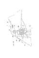
- FIG. 4 is an enlarged plan view of a part A in FIG.
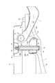
- FIG. 5 is a diagram obtained by rotating the enlarged BB cross-sectional view of FIG. 2 by 90 degrees counterclockwise.
- FIG. 6 is an operation explanatory view showing a state in which the impact load received from the side of the vehicle is input to the upper link with respect to FIG.
- the suspension device according to one embodiment of the present invention shown in FIG. 1 is a rear wheel suspension device at the rear of the vehicle.
- the direction shown by the arrow FR in the figure is the vehicle front.
- the subframe 1 extending in the vehicle width direction is fixed to the lower surface of the vehicle body having the side member 3, the cross member 5, the submember 6 and the like shown in FIG.
- the side members 3 are extended in the vehicle front-rear direction on both sides in the vehicle width direction, and the cross members 5 are extended in the vehicle width direction so as to connect the left and right side members 3 to each other.
- the sub member 6 extends in parallel with the side member 3 from the cross member 5 to the front of the vehicle at a position near the side member 3.
- the both ends of the upper link 7, the lower front link 9, and the lower rear link 11 in the vehicle width direction are connected to both sides of the subframe 1 in the vehicle width direction.
- the upper link 7 constitutes a suspension link.
- the ends of the upper link 7, the lower front link 9, and the lower rear link 11 on the outer side in the vehicle width direction are connected to a knuckle 13 that constitutes a wheel support member.
- An axle 15 and a brake rotor (not shown) are rotatably supported on the knuckle 13, and a road wheel (not shown) of a wheel 17 is connected and fixed to the axle 15.
- the wheel 17 includes a tire attached to the road wheel.
- the subframe 1 includes a central portion 1a extending in the vehicle width direction and side portions 1b extending forward from the both ends of the central portion 1a in the vehicle width direction.
- a front portion 1c extending toward the front side of the vehicle obliquely outward in the vehicle width direction is formed at the end portion of the side portion 1b on the vehicle front side.
- rear portions 1d extending toward the obliquely rear side of the vehicle outside in the vehicle width direction are formed on the vehicle rear side of both ends in the vehicle width direction of the central portion 1a.
- the subframe 1 is fixed to the side member 3 by a front fixing portion 19 at the front end of the front portion 1c and a rear fixing portion 21 at the front end of the rear portion 1d, and is arranged at a boundary portion between the side portion 1b and the front portion 1c. It is fixed to the sub member 6 by the inner fixing portion 23 positioned. That is, the subframe 1 is fixed to the vehicle body at a total of six locations, three on each of the left and right sides.
- fixed part 23 comprises the fixing
- the end portion 7a on the inner side in the vehicle width direction of the upper link 7 is connected to the upper surface of the subframe 1 via an upper link bracket 25 as an attachment member.
- the upper link bracket 25 is disposed adjacent to the outer side in the vehicle width direction of the inner fixing portion 23, as shown in FIG.
- the inner fixing portion 23 is located on the inner side in the vehicle width direction with respect to the upper link bracket 25 corresponding to the connection portion of the upper link 7 to the subframe 1.
- the inner fixing portion 23 is close to the connecting portion between the upper link 7 and the subframe 1 and is located on the inner side in the vehicle width direction with respect to the connecting portion.
- the upper link bracket 25 includes an end wall 25a that is located on the inner side in the vehicle width direction and extends in the vehicle front-rear direction, and a front wall 25b that extends outward from the vehicle front-rear direction both ends of the end wall 25a in the vehicle width direction. And a rear wall 25c.
- a plate-like member is integrally formed by press molding.
- the end 7a of the upper link 7 is positioned between the front wall 25b and the rear wall 25c, and the end 7a is rotatably connected to a support shaft 27 supported by the front wall 25b and the rear wall 25c.
- the inner fixing portion 23 is positioned on the extension line of the rear wall 25c toward the inner side in the vehicle width direction.
- the inner fixing portion 23 inserts the lower portion of the collar 29 as a cylindrical member into the through hole 1 e formed in the subframe 1 and welds and fixes the through portion.
- the upper portion of the collar 29 constitutes a protruding portion 29 a that protrudes upward from the subframe 1, and the upper end 29 a 1 of the protruding portion 29 a is brought into contact with the lower surface of the submember 6.
- a bolt 31 as a fastener is inserted into the collar 29 from below the subframe 1, and the bolt 31 is fastened to a nut 33 provided on the upper surface of the submember 6.
- the fastening structure in the inner fixing part 23 is basically the same as the fastening structure of the front fixing part 19 and the rear fixing part 21 with respect to the side member 3, and the subframe 1 is connected to the side member 3 by these fastening structures. And fastened to the sub member 6.
- the above-described upper link bracket 25 has its end wall 25a fixed to the outer wall of the collar 29 on the outer side in the vehicle width direction of the protruding portion 29a. That is, the protruding portion 29a of the collar 29 included in the inner fixing portion 23 is located on the inner side in the vehicle width direction (left side in FIG. 5) than the upper link bracket 25 corresponding to the connection portion of the upper link 7 to the subframe 1. Will be.
- the end of the lower front link 9 on the inner side in the vehicle width direction is connected to the lower surface of the subframe 1 via the lower front link bracket 35 as shown in FIG.
- the connection position of the lower front link bracket 35 with respect to the subframe 1 is substantially opposite to the upper link bracket 25 in the vertical direction with the subframe 1 interposed therebetween.
- the lower rear link 11 is provided with a mounting portion 37 for attaching a shock absorber (not shown) on the outer side in the vehicle width direction, and the lower portion of the knuckle 13 is rotated on the mounting portion 37. Installed as possible. Further, the lower rear link 11 is provided with a spring receiving portion 39 that receives the lower end of a suspension spring (not shown) on the inner side in the vehicle width direction of the mounting portion 37.
- the end portion on the inner side in the vehicle width direction of the lower rear link 11 is attached to the lower surface of the subframe 1 via the lower rear link bracket 41 as shown in FIG.
- the attachment position of the lower rear link bracket 41 to the subframe 1 is in the vicinity of the boundary between the central portion 1a and the side portion 1b of the subframe 1.
- the basic shapes of the lower front link bracket 35 and the lower rear link bracket 41 are substantially the same as those of the upper link bracket 25.
- the connecting structure of the lower front link 9 and the lower rear link 11 to the link brackets 35 and 41 is the same as the connecting structure of the upper link 7 to the upper link bracket 25.
- the input load acting on each of the links 7, 9, 11 includes a force component in a direction in which the links 7, 9, 11 are moved inward in the vehicle width direction.
- the upper link 7 of the links 7, 9, 11 is located on the outer side in the vehicle width direction of the inner fixing portion 23, and the upper link bracket 25 to which the end 7 a on the inner side in the vehicle width direction is connected. For this reason, as shown in FIG. 6, the input load F acting on the upper link 7 is transmitted to the inner fixed portion 23 via the support shaft 27 and the upper link bracket 25 and is input.
- the protruding portion 29a of the collar 29 receives the input load F described above, and suppresses the intrusion movement of the upper link bracket 25 inward in the vehicle width direction (upper side in FIG. 6). Even if the upper link bracket 25 is damaged by the input load F, the end portion 7a on the inner side in the vehicle width direction of the upper link 7 interferes with the protruding portion 29a of the collar 29, and the upper link bracket 25 moves inwardly in the vehicle width direction. Suppress. As a result, damage to vehicle-mounted components mounted on the lower portion of the vehicle body in the vehicle width direction inside of the upper link 7 can be suppressed.
- the movement of the upper link 7 is suppressed by using the inner fixing portion 23 for fixing the subframe 1 to the vehicle body. Therefore, it is possible to suppress the invasion movement of the upper link 7 to the inside in the vehicle width direction without adding a separate dedicated structure for suppressing the movement of the upper link 7, and the existing structure can be used as it is. Cost increase can be suppressed.
- Examples of the on-vehicle components described above include a fuel tank and a battery used for an electric vehicle.
- the lower side facing the road surface is strengthened by measures such as chipping, but the upper side does not take special measures such as the lower side. Therefore, by preventing the upper link 7 located at the position corresponding to the upper side of the fuel tank or battery from entering inward in the vehicle width direction, damage to the fuel tank or battery can be efficiently suppressed.
- the lower front link 9 and the lower rear link 11 do not employ a structure that suppresses movement inward in the vehicle width direction like the upper link 7.
- these links 9 and 11 are located at a position corresponding to the lower side where the measures for the strength of the fuel tank and the battery are taken, or are located below the fuel tank and the battery. However, damage to the fuel tank and the battery is suppressed.
- the upper link 7 is connected to the subframe 1 via the upper link bracket 25, and the upper link bracket 25 is coupled to the protruding portion 29a of the collar 29 on the inner side in the vehicle width direction.
- the input load F acting on the upper link 7 is reliably transmitted from the upper link bracket 25 by the protruding portion 29a of the collar 29 in the inner fixing portion 23, and the intrusion movement of the upper link 7 to the inner side in the vehicle width direction is further increased. It can be surely suppressed.
- the upper link bracket 25 is coupled to the collar 29, the upper link bracket 25 is displaced in the vehicle longitudinal direction with respect to the collar 29 when an impact load is transmitted from the upper link bracket 25 to the collar 29. Can be suppressed. Thus, the impact load can be reliably transmitted from the upper link bracket 25 to the protruding portion 29a of the collar 29.
- the protrusion 29 a of the collar 29 in the inner fixing portion 23 is set at a position corresponding to the rear wall 25 c of the upper link bracket 25.
- the input load F (see FIG. 6) that acts on the upper link 7 acts on the protruding portion 29a of the collar 29 via the rear wall 25c extending in the vehicle width direction. Intrusion movement can be more reliably suppressed.
- the inner fixing portion 23 includes a collar 29 into which the bolt 31 is inserted when the subframe 1 and the vehicle body are fastened and fixed. For this reason, in order to suppress the invasion movement of the upper link 7 in the vehicle width direction, the collar 29 into which the bolt 31 is inserted can be used effectively.
- the rear wheel suspension device of the rear portion of the vehicle has been described, but the present invention can also be applied to a front wheel suspension device of the front portion of the vehicle.
- the upper link bracket 25 is connected to the protruding portion 29a of the collar 29 on the inner side in the vehicle width direction, but may be separated from the protruding portion 29a. Further, the protruding portion 29a of the collar 29 is set at a position corresponding to the rear wall 25c of the upper link bracket 25, but may be set at a position corresponding to the front wall 25b.
- the structure that suppresses the movement in the vehicle width direction inner side only with respect to the upper link 7 is adopted, but the movement of the lower front link 9 and the lower rear link 11 in the vehicle width direction inner side is performed.
- a suppressing structure may be employed. That is, in this case, a fixing part to the vehicle body of the subframe 1 is arranged on the inner side in the vehicle width direction of the lower front link bracket 35 and the lower rear link bracket 41, and the lower front link 9 and Intrusion movement of the lower rear link 11 to the inner side in the vehicle width direction is suppressed.
- the inner fixing portion 23 of the subframe 1 is fixed to the submember 6 of the vehicle body, but may be fixed to the cross member 5 depending on the shape of the vehicle body.
- the sub member 6 is in a state parallel to the side member 3, the sub member 6 may be arranged obliquely to connect the side member 3 and the cross member 5.
- the present invention is applied to a suspension device in which a suspension link is connected to a subframe fixed to a vehicle body.
- Subframe 3 Side member (vehicle body) 5 Cross member (car body) 6 Submember (car body) 7 Upper link (suspension link) 7a End of the upper link in the vehicle width direction 13 Knuckle (wheel support member) 17 Wheel 23 Inner fixing part (fixing part) 25 Upper link bracket (mounting member) 25a End wall of upper link bracket 25b Front wall of upper link bracket 25c Rear wall of upper link bracket 29 Collar (cylindrical member) 31 bolts (fasteners)
Landscapes
- Engineering & Computer Science (AREA)
- Chemical & Material Sciences (AREA)
- Combustion & Propulsion (AREA)
- Transportation (AREA)
- Mechanical Engineering (AREA)
- Body Structure For Vehicles (AREA)
Abstract
サブフレーム1は、サイドメンバやクロスメンバを備える車体の下面に固定される。サブフレーム1の車幅方向両側には、アッパリンク7、ロア前部リンク9及びロア後部リンク11の車幅方向内側の端部が連結される。このうちアッパリンク7は、サブフレーム1の上面にアッパリンクブラケット25を介して取り付けられる。アッパリンクブラケット25の車幅方向内側に、サブフレーム1を車体に固定するための内側固定部23のカラー29が位置している。カラー29には、サブフレーム1を車体に締結固定するためのボルトが下方から挿入される。
Description
本発明は、車体に固定したサブフレームにサスペンションリンクが連結されるサスペンション装置に関する。
従来のサスペンション装置として、下記特許文献1に記載されたものが知られている。特許文献1のサスペンション装置は、車体に固定したサブフレームに、サスペンションリンクである5本のリンクの車幅方向内側の端部を連結している。各リンクの車幅方向外側の端部は、車輪の支持部材に連結している。
従来のサスペンション装置では、車両が側方から衝撃荷重を受け、その際車輪に側方から入力された荷重によって、サスペンションリンクが車幅方向内側に侵入する恐れがある。
そこで、本発明は、車両側方から車輪に入力された荷重によって、サスペンションリンクが車幅方向内側に侵入するのを抑制することを目的としている。
本発明は、サブフレームを車体に固定する固定部を備え、固定部は、サスペンションリンクとサブフレームとの連結部位に近接し、且つ、連結部位に対して車幅方向内側に位置している。
本発明によれば、車両側方から車輪に入力される衝撃荷重はサスペンションリンクに伝達され、その際サスペンションリンクの車幅方向内側への侵入移動は、サブフレームを車体に固定する固定部によって抑制される。
以下、本発明を実施するための形態について、図面を参照して詳細に説明する。図1に示す本発明の一実施形態に係わるサスペンション装置は、車両後部の後輪サスペンション装置である。なお、図中の矢印FRで示す方向が車両前方である。
後輪サスペンション装置は、車幅方向に延設されるサブフレーム1を、図2に示すサイドメンバ3、クロスメンバ5及びサブメンバ6などを有する車体の下面に固定している。サイドメンバ3は、車幅方向両側にて車両前後方向に延設され、クロスメンバ5は、左右のサイドメンバ3相互を連結するように車幅方向に延設されている。サブメンバ6は、サイドメンバ3の近傍位置でクロスメンバ5から車両前方にサイドメンバ3と並行して延設されている。
サブフレーム1の車幅方向両側には、アッパリンク7、ロア前部リンク9及びロア後部リンク11のそれぞれの車幅方向内側の端部が連結されている。アッパリンク7はサスペンションリンクを構成している。また、アッパリンク7、ロア前部リンク9及びロア後部リンク11のそれぞれの車幅方向外側の端部は、車輪の支持部材を構成するナックル13に連結されている。
ナックル13には、車軸15及び図示しないブレーキロータが回転可能に支持され、車軸15に車輪17の図示しないロードホイールが連結固定される。車輪17は、ロードホイールに装着されるタイヤを含む。
サブフレーム1は、図2の平面図で示すように、車幅方向に延びる中央部1aと、中央部1aの車幅方向両端部から車両前方に延びる側部1bとを備えている。側部1bの車両前方側の端部には、車幅方向外側の車両斜め前方側に向けて延びる前部1cが形成されている。また、中央部1aの車幅方向両端部の車両後方側には、車幅方向外側の車両斜め後方側に向けて延びる後部1dが形成されている。
サブフレーム1は、前部1cの先端の前固定部19と、後部1dの先端の後固定部21とによって、サイドメンバ3に固定され、側部1bと前部1cとの間の境界部に位置する内側固定部23によって、サブメンバ6に固定される。すなわち、サブフレーム1は、左右3箇所ずつ全部で6箇所にて車体に固定される。なお、内側固定部23は、サブフレーム1を車体に固定する固定部を構成している。
前記したアッパリンク7の車幅方向内側の端部7aは、取付部材としてのアッパリンクブラケット25を介してサブフレーム1の上面に連結している。アッパリンクブラケット25は、図2のA部を拡大した図4に示すように、内側固定部23の車幅方向外側に隣接して配置してある。換言すれば、内側固定部23は、アッパリンク7のサブフレーム1に対する連結部位に相当するアッパリンクブラケット25よりも車幅方向内側に位置している。すなわち、内側固定部23は、アッパリンク7とサブフレーム1との連結部位に近接し、且つ、連結部位に対して車幅方向内側に位置している。
図4に示すように、アッパリンクブラケット25は、車幅方向内側に位置して車両前後方向に延びる端壁25aと、端壁25aの車両前後方向両端縁から車幅方向外側に延びる前壁25b及び後壁25cとを備えている。このようなアッパリンクブラケット25は、板状部材をプレス成形によって一体的に形成している。前壁25bと後壁25cとの間にアッパリンク7の端部7aが位置して、該端部7aが前壁25b及び後壁25cに支持される支持軸27に回転可能に連結されている。
そして、端壁25aの後壁25c側の端部付近を内側固定部23の外周面に溶接固定している。この場合、後壁25cの車幅方向内側への延長線上に内側固定部23が位置している。
内側固定部23は、図5に示すように、円筒部材としてのカラー29の下部を、サブフレーム1に形成した貫通孔1eに挿入してその貫通部位を溶接固定する。カラー29の上部は、サブフレーム1から上方に向けて突出する突出部29aを構成し、突出部29aの上端29a1をサブメンバ6の下面に当接させる。
そして、サブフレーム1の下方から締結具としてのボルト31をカラー29内に挿入し、サブメンバ6の上面に設けてあるナット33にボルト31を締結する。このような内側固定部23における締結構造は、サイドメンバ3に対する前固定部19及び後固定部21の締結構造と基本的には同様であり、これらの締結構造によって、サブフレーム1がサイドメンバ3及びサブメンバ6に締結固定される。
ここで、図5に示すように、前記したアッパリンクブラケット25は、その端壁25aを、カラー29における突出部29aの車幅方向外側の外壁に溶接固定している。すなわち、内側固定部23に含まれるカラー29の突出部29aは、アッパリンク7のサブフレーム1に対する連結部位に相当するアッパリンクブラケット25よりも車幅方向内側(図5中で左側)に位置していることになる。
前記したロア前部リンク9の車幅方向内側の端部は、図3に示すように、ロア前部リンクブラケット35を介してサブフレーム1の下面に連結している。ロア前部リンクブラケット35のサブフレーム1に対する連結位置は、サブフレーム1を間に挟みアッパリンクブラケット25に対して上下方向のほぼ反対側となっている。
また、前記したロア後部リンク11は、図1、図2に示すように、車幅方向外側に、図示しないショックアブソーバを取り付ける取付部37を設けてあり、取付部37にナックル13の下部を回転可能に取り付けている。さらに、ロア後部リンク11は、取付部37の車幅方向内側に、図示しないサスペンションスプリングの下端を受けるスプリング受部39を設けている。
ロア後部リンク11の車幅方向内側の端部は、図3に示すように、ロア後部リンクブラケット41を介してサブフレーム1の下面に取り付けている。ロア後部リンクブラケット41のサブフレーム1への取付位置は、サブフレーム1の中央部1aと側部1bとの境界付近である。
ロア前部リンクブラケット35及びロア後部リンクブラケット41の基本的な形状は、アッパリンクブラケット25とほぼ同様である。また、これらリンクブラケット35,41に対するロア前部リンク9、ロア後部リンク11のそれぞれの連結構造も、アッパリンクブラケット25に対するアッパリンク7の連結構造と同様である。
次に作用を説明する。
上記したサスペンション装置を備える自動車が側方から衝撃荷重を受け、その衝撃荷重が車輪17に入力されると、その入力荷重は、ナックル13を介してアッパリンク7、ロア前部リンク9及びロア後部リンク11にそれぞれ作用する。この各リンク7,9,11に作用する入力荷重は、各リンク7,9,11を車幅方向内側に移動させる方向の力の成分を含んでいる。
上記各リンク7,9,11のうちアッパリンク7については、車幅方向内側の端部7aが連結されるアッパリンクブラケット25が、内側固定部23の車幅方向外側に位置している。このため、図6に示すように、アッパリンク7に作用した入力荷重Fは、支持軸27及びアッパリンクブラケット25を介して内側固定部23に伝達されて入力される。
このとき内側固定部23は、カラー29の突出部29aが上記した入力荷重Fを受け止めて、アッパリンクブラケット25の車幅方向内側(図6中で上側)への侵入移動を抑制する。入力荷重Fによってアッパリンクブラケット25が破損しても、アッパリンク7の車幅方向内側の端部7aがカラー29の突出部29aに干渉し、アッパリンクブラケット25の車幅方向内側への侵入移動を抑制する。これにより、アッパリンク7の車幅方向内側方向の車体下部に搭載される車両搭載部品の損傷を抑えることができる。
その際、本実施形態では、サブフレーム1を車体に固定するための内側固定部23を利用してアッパリンク7の移動を抑制している。このため、アッパリンク7の移動を抑制するための別途専用の構造を追加することなく、アッパリンク7の車幅方向内側のへの侵入移動を抑制でき、既存の構造をそのまま利用でき、その分コストアップを抑えることができる。
上記した車両搭載部品としては、例えば燃料タンクや電気自動車に使用されるバッテリなどがある。燃料タンクやバッテリは、路面に対向する下部側がチッピング対策などで強度を高めているが、上部側は下部側のような対策を特に施していない。したがって、燃料タンクやバッテリの上部側に対応する位置にあるアッパリンク7の車幅方向内側への侵入移動を抑制することで、燃料タンクやバッテリの破損を効率よく抑えることができる。
ロア前部リンク9及びロア後部リンク11については、アッパリンク7のように車幅方向内側への移動を抑制する構造を採用していない。しかし、これらリンク9,11は、燃料タンクやバッテリの強度対策を施してある下部側に対応する位置にあるか、もしくは燃料タンクやバッテリよりも下方に位置するので、車幅方向内側に移動しても、燃料タンクやバッテリの損傷は抑制される。
また、本実施形態では、アッパリンク7は、アッパリンクブラケット25を介してサブフレーム1に連結され、アッパリンクブラケット25は、車幅方向内側がカラー29の突出部29aに結合されている。このため、アッパリンク7に作用した入力荷重Fは、アッパリンクブラケット25から内側固定部23におけるカラー29の突出部29aにより確実に伝達され、アッパリンク7の車幅方向内側への侵入移動をより確実に抑えることができる。
さらに、アッパリンクブラケット25がカラー29に結合されていることで、衝撃荷重がアッパリンクブラケット25からカラー29に伝達される際に、アッパリンクブラケット25がカラー29に対して車両前後方向にずれるのを抑制できる。これによって、衝撃荷重をアッパリンクブラケット25からカラー29の突出部29aにより確実に伝達することができる。
また、本実施形態では、図4示すように、内側固定部23におけるカラー29の突出部29aは、アッパリンクブラケット25の後壁25cに対応する位置に設定されている。この場合、アッパリンク7に作用した入力荷重F(図6参照)が、車幅方向に延びる後壁25cを介してカラー29の突出部29aに作用するので、アッパリンク7の車幅方向内側への侵入移動をより確実に抑えることができる。
また、本実施形態では、内側固定部23は、サブフレーム1と車体とを締結固定する際にボルト31が挿入されるカラー29を備えている。このため、アッパリンク7の車幅方向内側への侵入移動を抑えるために、ボルト31が挿入されるカラー29を有効利用することができる。
以上、本発明の実施形態について説明したが、これらの実施形態は本発明の理解を容易にするために記載された単なる例示に過ぎず、本発明は当該実施形態に限定されるものではない。本発明の技術的範囲は、上記実施形態で開示した具体的な技術事項に限らず、そこから容易に導きうる様々な変形、変更、代替技術なども含むものである。
例えば、上記した実施形態では、車両後部の後輪サスペンション装置について説明したが、車両前部の前輪サスペンション装置に対しても本発明を適用することができる。また、アッパリンクブラケット25は、車幅方向内側がカラー29の突出部29aに結合されているが、突出部29aに対して離間していてもよい。さらに、カラー29の突出部29aは、アッパリンクブラケット25の後壁25cに対応する位置に設定されているが、前壁25bに対応する位置に設定されていてもよい。
また、上記した実施形態では、アッパリンク7に対してのみ車幅方向内側への移動を抑制する構造を採用したが、ロア前部リンク9及びロア後部リンク11の車幅方向内側への移動を抑制する構造を採用してもよい。すなわち、この場合には、ロア前部リンクブラケット35及びロア後部リンクブラケット41の車幅方向内側に、サブフレーム1の車体への固定部を配置して、該固定部によってロア前部リンク9及びロア後部リンク11の車幅方向内側への侵入移動を抑制する。
また、上記した実施形態では、サブフレーム1の内側固定部23を、車体のサブメンバ6に固定しているが、車体の形状によってはクロスメンバ5に固定することもできる。サブメンバ6は、サイドメンバ3と並行した状態となっているが、斜めに配置してサイドメンバ3とクロスメンバ5とを連結する構成でもよい。
本発明は、車体に固定したサブフレームにサスペンションリンクが連結されるサスペンション装置に適用される。
1 サブフレーム
3 サイドメンバ(車体)
5 クロスメンバ(車体)
6 サブメンバ(車体)
7 アッパリンク(サスペンションリンク)
7a アッパリンクの車幅方向内側の端部
13 ナックル(車輪の支持部材)
17 車輪
23 内側固定部(固定部)
25 アッパリンクブラケット(取付部材)
25a アッパリンクブラケットの端壁
25b アッパリンクブラケットの前壁
25c アッパリンクブラケットの後壁
29 カラー(円筒部材)
31 ボルト(締結具)
3 サイドメンバ(車体)
5 クロスメンバ(車体)
6 サブメンバ(車体)
7 アッパリンク(サスペンションリンク)
7a アッパリンクの車幅方向内側の端部
13 ナックル(車輪の支持部材)
17 車輪
23 内側固定部(固定部)
25 アッパリンクブラケット(取付部材)
25a アッパリンクブラケットの端壁
25b アッパリンクブラケットの前壁
25c アッパリンクブラケットの後壁
29 カラー(円筒部材)
31 ボルト(締結具)
Claims (4)
- 固定部により車体に固定されるサブフレームと、
前記サブフレームに車幅方向内側の端部が連結され、車幅方向外側の端部が車輪の支持部材に連結されるサスペンションリンクと、を有し、
前記固定部は、前記サスペンションリンクと前記サブフレームとの連結部位に近接し、且つ、前記連結部位に対して車幅方向内側に位置していることを特徴とするサスペンション装置。 - 前記サスペンションリンクの車幅方向内側の端部は、取付部材を介して前記サブフレームに連結され、
前記取付部材は、車幅方向内側が前記固定部に結合されていることを特徴とする請求項1に記載のサスペンション装置。 - 前記取付部材は、車幅方向内側に位置して車両前後方向に延びる端壁と、前記端壁の車両前後方向両端縁から車幅方向外側に延び、前記サスペンションリンクを支持する前壁及び後壁と、を備え、
前記固定部は、前記前壁と前記後壁とのいずれか一方に対応する位置に設定されていることを特徴とする請求項2に記載のサスペンション装置。 - 前記固定部は、前記サブフレームと車体とを締結固定する際に締結具が挿入される円筒部材を備えていることを特徴とする請求項1ないし3のいずれか1項に記載のサスペンション装置。
Priority Applications (1)
| Application Number | Priority Date | Filing Date | Title |
|---|---|---|---|
| PCT/JP2014/065320 WO2015189909A1 (ja) | 2014-06-10 | 2014-06-10 | サスペンション装置 |
Applications Claiming Priority (1)
| Application Number | Priority Date | Filing Date | Title |
|---|---|---|---|
| PCT/JP2014/065320 WO2015189909A1 (ja) | 2014-06-10 | 2014-06-10 | サスペンション装置 |
Publications (1)
| Publication Number | Publication Date |
|---|---|
| WO2015189909A1 true WO2015189909A1 (ja) | 2015-12-17 |
Family
ID=54833041
Family Applications (1)
| Application Number | Title | Priority Date | Filing Date |
|---|---|---|---|
| PCT/JP2014/065320 Ceased WO2015189909A1 (ja) | 2014-06-10 | 2014-06-10 | サスペンション装置 |
Country Status (1)
| Country | Link |
|---|---|
| WO (1) | WO2015189909A1 (ja) |
Cited By (2)
| Publication number | Priority date | Publication date | Assignee | Title |
|---|---|---|---|---|
| US20210354758A1 (en) * | 2020-05-14 | 2021-11-18 | Hyundai Motor Company | Vehicle sub-frame and method of manufacturing same |
| US20220306203A1 (en) * | 2021-03-29 | 2022-09-29 | Honda Motor Co., Ltd. | Subframe |
Citations (5)
| Publication number | Priority date | Publication date | Assignee | Title |
|---|---|---|---|---|
| JPS6312412U (ja) * | 1986-03-13 | 1988-01-27 | ||
| JPH0645286B2 (ja) * | 1985-10-21 | 1994-06-15 | トヨタ自動車株式会社 | 車両のサスペンシヨン |
| JP2005206079A (ja) * | 2004-01-23 | 2005-08-04 | Mazda Motor Corp | 自動車のペリメータフレーム構造 |
| JP2010012882A (ja) * | 2008-07-02 | 2010-01-21 | Nissan Motor Co Ltd | サスペンション装置 |
| JP2013049321A (ja) * | 2011-08-30 | 2013-03-14 | Toyota Motor Corp | 車体前部構造 |
-
2014
- 2014-06-10 WO PCT/JP2014/065320 patent/WO2015189909A1/ja not_active Ceased
Patent Citations (5)
| Publication number | Priority date | Publication date | Assignee | Title |
|---|---|---|---|---|
| JPH0645286B2 (ja) * | 1985-10-21 | 1994-06-15 | トヨタ自動車株式会社 | 車両のサスペンシヨン |
| JPS6312412U (ja) * | 1986-03-13 | 1988-01-27 | ||
| JP2005206079A (ja) * | 2004-01-23 | 2005-08-04 | Mazda Motor Corp | 自動車のペリメータフレーム構造 |
| JP2010012882A (ja) * | 2008-07-02 | 2010-01-21 | Nissan Motor Co Ltd | サスペンション装置 |
| JP2013049321A (ja) * | 2011-08-30 | 2013-03-14 | Toyota Motor Corp | 車体前部構造 |
Cited By (4)
| Publication number | Priority date | Publication date | Assignee | Title |
|---|---|---|---|---|
| US20210354758A1 (en) * | 2020-05-14 | 2021-11-18 | Hyundai Motor Company | Vehicle sub-frame and method of manufacturing same |
| US11505250B2 (en) * | 2020-05-14 | 2022-11-22 | Hyundai Motor Company | Vehicle sub-frame and method of manufacturing same |
| US20220306203A1 (en) * | 2021-03-29 | 2022-09-29 | Honda Motor Co., Ltd. | Subframe |
| US12043312B2 (en) * | 2021-03-29 | 2024-07-23 | Honda Motor Co., Ltd. | Subframe |
Similar Documents
| Publication | Publication Date | Title |
|---|---|---|
| EP2990307B1 (en) | Rear part structure of vehicle | |
| EP2749478B1 (en) | Structure for front section of vehicle body | |
| US9139229B2 (en) | Structure for rear part of vehicle body | |
| JP5870680B2 (ja) | 自動車のフロントサブフレーム構造 | |
| US20140191105A1 (en) | Engine cradle with deflector device | |
| JP5870673B2 (ja) | 自動車のフロントサブフレーム構造 | |
| CN105593037B (zh) | 用于车辆的车辆前部结构 | |
| KR101526411B1 (ko) | 후방 차체 보강구조 | |
| JP6547782B2 (ja) | 車両下部構造 | |
| US20190077207A1 (en) | Vehicle and suspension arm | |
| CN104554465A (zh) | 悬架支撑罩构造 | |
| JP2013049321A (ja) | 車体前部構造 | |
| JP5942811B2 (ja) | 車両の下部構造 | |
| KR101795396B1 (ko) | 전기 자동차 배터리 마운팅 보강 구조 | |
| CN201922879U (zh) | 一种汽车车身后减振器座的安装结构 | |
| CN107433980A (zh) | 车辆的悬架安装部结构 | |
| WO2015189909A1 (ja) | サスペンション装置 | |
| JP6572589B2 (ja) | 車両の前輪懸架構造 | |
| KR20120007608U (ko) | 보조쇽업소버 장착을 위한 보조브래킷 | |
| JP5509265B2 (ja) | 車体前部構造 | |
| JP2022048806A (ja) | スタビライザ装置 | |
| JP6136302B2 (ja) | ステアリングナックルの構造 | |
| KR101251751B1 (ko) | 차체의 전방 연결구조 | |
| KR101703610B1 (ko) | 차량용 서브 프레임 | |
| KR101399336B1 (ko) | 차량용 범퍼 빔 유닛 |
Legal Events
| Date | Code | Title | Description |
|---|---|---|---|
| 121 | Ep: the epo has been informed by wipo that ep was designated in this application |
Ref document number: 14894641 Country of ref document: EP Kind code of ref document: A1 |
|
| NENP | Non-entry into the national phase |
Ref country code: DE |
|
| NENP | Non-entry into the national phase |
Ref country code: JP |
|
| 122 | Ep: pct application non-entry in european phase |
Ref document number: 14894641 Country of ref document: EP Kind code of ref document: A1 |