WO2015186762A1 - エンジンの燃料噴射制御装置 - Google Patents
エンジンの燃料噴射制御装置 Download PDFInfo
- Publication number
- WO2015186762A1 WO2015186762A1 PCT/JP2015/066105 JP2015066105W WO2015186762A1 WO 2015186762 A1 WO2015186762 A1 WO 2015186762A1 JP 2015066105 W JP2015066105 W JP 2015066105W WO 2015186762 A1 WO2015186762 A1 WO 2015186762A1
- Authority
- WO
- WIPO (PCT)
- Prior art keywords
- engine
- feedback
- sensor
- fuel injection
- increase correction
- Prior art date
- Legal status (The legal status is an assumption and is not a legal conclusion. Google has not performed a legal analysis and makes no representation as to the accuracy of the status listed.)
- Ceased
Links
Images



Classifications
-
- F—MECHANICAL ENGINEERING; LIGHTING; HEATING; WEAPONS; BLASTING
- F02—COMBUSTION ENGINES; HOT-GAS OR COMBUSTION-PRODUCT ENGINE PLANTS
- F02D—CONTROLLING COMBUSTION ENGINES
- F02D41/00—Electrical control of supply of combustible mixture or its constituents
- F02D41/02—Circuit arrangements for generating control signals
- F02D41/04—Introducing corrections for particular operating conditions
-
- F—MECHANICAL ENGINEERING; LIGHTING; HEATING; WEAPONS; BLASTING
- F02—COMBUSTION ENGINES; HOT-GAS OR COMBUSTION-PRODUCT ENGINE PLANTS
- F02D—CONTROLLING COMBUSTION ENGINES
- F02D41/00—Electrical control of supply of combustible mixture or its constituents
- F02D41/02—Circuit arrangements for generating control signals
- F02D41/14—Introducing closed-loop corrections
-
- F—MECHANICAL ENGINEERING; LIGHTING; HEATING; WEAPONS; BLASTING
- F02—COMBUSTION ENGINES; HOT-GAS OR COMBUSTION-PRODUCT ENGINE PLANTS
- F02D—CONTROLLING COMBUSTION ENGINES
- F02D45/00—Electrical control not provided for in groups F02D41/00 - F02D43/00
Definitions
- the present invention relates to an engine fuel injection control device mounted on a vehicle, and more particularly to an engine fuel injection control device that improves exhaust gas characteristics by preventing engine overheating when the vehicle is in a fully open running state.
- the fuel injection amount is increased to enrich the in-cylinder air-fuel ratio of the engine (the latent heat of vaporization).
- the fully open running state it is unavoidably disadvantageous in terms of exhaust gas characteristics and the like (in terms of fuel consumption) as compared with the normal running state.
- Patent Document 1 requires that the in-cylinder air-fuel ratio be sufficiently enriched by a large fuel increase so that overheating of the engine can be prevented.
- an increase in the fuel hinders the leaning of the exhaust air-fuel ratio (the air-fuel ratio after the averaging of rich and lean), and consequently the improvement of exhaust gas characteristics.
- the increase in fuel is suppressed by giving priority to improving the exhaust gas characteristics, the enrichment of the in-cylinder air-fuel ratio is hindered, and the problem is that overheating of the engine is promoted due to a decrease in latent heat of vaporization.
- the present invention has been made in order to solve such problems.
- the object of the present invention is to achieve both high-dimensional prevention of engine damage and improvement of exhaust gas characteristics due to overheating of the vehicle when the vehicle is fully opened.
- An object of the present invention is to provide a fuel injection control device for an engine.
- an engine fuel injection control device comprises a fully open determining means for determining whether or not a vehicle is in a fully open running state in which the throttle is fully open and the engine rotational speed is balanced,
- the fuel injection amount of the engine is increased and corrected to increase the air-fuel ratio, and the fully open determining means is used to fully open the traveling state.
- the increase correction amount by the injection amount control means is gradually decreased to a preset hold value, and the increase correction amount is kept at the hold value and held until the preset hold period elapses after the decrease.
- a fully open leaning means for gradually increasing the increase correction amount from the hold value and returning to the value before the decrease when the period has elapsed.
- the increase correction amount is decreased based on the determination of the fully open traveling state at an early stage, and the air-fuel ratio of the engine is maintained over the holding period. And lean.
- the holding period even if the air-fuel ratio is made lean, there is no fear of engine damage, and the exhaust gas characteristics are improved by leaning.
- the thermal margin can be effectively used for leaning the air-fuel ratio, and the engine is fully opened. It is unpredictable how long the running state will continue, but even if it is completed in a short time, the leaning over the holding period has already been completed, so the effect of leaning will not change at all. It is done.
- a catalyst device provided in the exhaust passage of the engine, an O 2 sensor provided on the upstream side of the catalyst device in the exhaust passage, and an activation determination for determining whether or not the O 2 sensor is activated.
- the engine fuel injection amount is feedback controlled based on the output of the O 2 sensor to bring the engine exhaust air-fuel ratio close to the theoretical air-fuel ratio.
- a O 2 feedback means to maintain is fully open when leaning means controls the fuel injection quantity of the engine to the stoichiometric air-fuel ratio corresponding value during the holding period, O 2 feedback means, the O 2 sensor during the life It is desirable to perform the feedback control based on the output.
- the exhaust air / fuel ratio of the engine can be reliably controlled within the catalyst device window centered on the theoretical air / fuel ratio by feedback control based on the output of the O 2 sensor during the holding period, and the purification Function is further improved.
- the O 2 feedback unit is configured to start feedback control based on the output of the O 2 sensor from that point when activation of the O 2 sensor is determined by the activation determination unit during the holding period. It is desirable to do. In such a configuration, even if the O 2 sensor is not activated at the beginning of the holding period, feedback control based on the output of the O 2 sensor is started as soon as the O 2 sensor is activated. Accurate air-fuel ratio control is realized, and as a result, the purification function of the catalyst device can be maximized.
- the fully open leaning means decreases the increase correction amount to the hold value and the output of the O 2 sensor reaches a lean determination value set in the vicinity of the theoretical air-fuel ratio in advance
- the increase correction amount is regarded as a holding value, and the decrease of the increase correction amount is stopped and kept.
- the O 2 feedback means starts from the time when the fully open leaning means stops the decrease of the increase correction amount based on the output of the O 2 sensor. It is desirable that the feedback control based on the outputs of the two sensors is started. In such a configuration, when the output of the O 2 sensor reaches the lean determination value, it can be estimated that the engine exhaust air-fuel ratio exceeds the stoichiometric air-fuel ratio and is reversed to the lean side.
- the fully open leaning means when the fully open leaning means returns the increase correction amount from the hold value to the value before the decrease as the hold period elapses, it is set based on the output of the O 2 sensor when the hold period elapses. It is desirable to configure the value corresponding to the feedback correction amount being the first change of the increase correction amount. When configured in this way, the torque change of the engine when the increase correction amount is returned to the value before the decrease is suppressed, and the deterioration of the running feeling due to the torque shock is prevented.
- the value corresponding to the feedback correction amount is set as the initial decrease of the increase correction amount. It is desirable that the increase correction amount be gradually increased after the first time.
- the increase correction amount is decreased and increased by the fully open leaning means based on the determination of the fully open running state by the fully open determining means, the increase is again increased even if the determination of the fully open running state is continued. It is desirable to further include an increase / decrease prohibiting means for prohibiting the reduction and increase of the correction amount from being made to the fully open leaning means. When configured in this way, it is possible to prevent the increase correction amount from decreasing and increasing again when the engine has no thermal margin.
- the O 2 feedback means during learning operation for learning feedback control by the O 2 feedback means based on the output of the O 2 sensor during operation of the engine other than the fully open running state, and during feedback control by the O 2 feedback means during the holding period It is desirable to further include learning prohibiting means for prohibiting the learning means from executing the learning process.
- learning prohibiting means for prohibiting the learning means from executing the learning process.
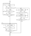
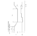
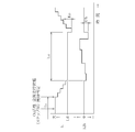
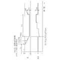
- 1 is a system configuration diagram showing an engine fuel injection control device of an embodiment. It is a flowchart which shows the full open stoichiometric control routine which ECU performs. It is a flowchart which shows the full open stoichiometric control routine which ECU performs. It is a time chart which shows the execution situation of full-open stoichiometric control when the O 2 sensor has already been activated before the start of the full-open running state and the O 2 feedback is completed on the rich side. It is a time chart which shows the execution situation of full-open stoichiometric control when the O 2 sensor has already been activated before the start of the full-open running state and the O 2 feedback is finished on the lean side.
- FIG. 1 is a system configuration diagram showing an engine fuel injection control device of the present embodiment.
- the engine 1 of this embodiment is configured as a four-cycle single-cylinder gasoline engine with a displacement of 50 cc, and is mounted on a vehicle as a driving power source.
- the specification of the engine 1 is not limited to this, and can be arbitrarily changed. For example, it may be applied to a large displacement multi-cylinder engine.
- a piston 4 is slidably disposed in a cylinder 3 formed in a cylinder block 2 of the engine 1.
- the piston 4 is connected to a crankshaft 6 via a connecting rod 5 and interlocked with the reciprocating motion of the piston 4.
- the crankshaft 6 rotates.
- a flywheel 7 is attached to the rear end of the crankshaft 6 (on the transmission side (not shown)), and in a predetermined angular region on the outer periphery of the flywheel 7, there is a retractor projection 7a made of a magnetic material for detecting the crank angle. Is formed.
- an intake port 9a and an exhaust port 9b are formed, and a spark plug 10 is disposed in a posture in which the tip faces the inside of the cylinder.
- An intake passage 11 connected to the intake port 9a has an air cleaner 12 from the upstream side, a throttle valve 13 that opens and closes in response to the driver's throttle operation, a bypass passage 15 having an ISCV (idle speed control valve) 14, and An injector 16 that injects fuel toward the intake port 9a is provided.
- the exhaust passage 17 connected to the exhaust port 9b is provided with a three-way catalyst 18 (catalyst device) for purifying exhaust gas and a silencer (not shown).
- An intake valve 20 is disposed in the intake port 9a, and an exhaust valve 21 is disposed in the exhaust port 9b.
- These intake and exhaust valves 20 and 21 are urged toward the valve closing side by a valve spring 22 and are opened by an intake camshaft 23 and an exhaust camshaft 24 that are driven to rotate in synchronization with the crankshaft 6 on the cylinder head 9.
- the intake valve 20 and the exhaust valve 21 are opened and closed at a predetermined timing synchronized with the reciprocation of the piston 4, and the combustion cycle of the engine 1 consisting of four strokes of intake, compression, expansion and exhaust is 720 ° CA in crank angle. Repeated every time.
- the fuel (gasoline) stored in the fuel tank 25 is supplied to the injector 16 by a fuel pump 26.
- the fuel pump 26 is integrated with the injector 16 and connected to the fuel tank 25 via a supply hose 27 and a return hose 28, respectively.
- the fuel in the fuel tank 25 is introduced into the fuel pump 26 through the supply hose 27 and pressurized to a predetermined pressure, and the pressurized fuel is supplied to the injector 16 and surplus fuel is supplied. Is recovered in the fuel tank 25 via the return hose 28.
- fuel of a predetermined pressure is always supplied to the injector 16, and the fuel is injected toward the intake port 9a at a predetermined injection timing and injection amount according to the opening of the injector 16.
- the combustion cycle of the engine 1 described above is executed based on the control of the ECU 31 (engine control unit).
- ECU 31 engine control unit
- an electromagnetic pickup 32 that is arranged opposite to the flywheel 7 and outputs a detection signal synchronized with the reluctator protrusion 7 a
- a throttle sensor 33 that detects the opening of the throttle valve 13
- an exhaust passage 17 Various sensors such as an O 2 sensor 34 that is arranged and varies the output VS in a step-like manner according to a variation in the exhaust air-fuel ratio centered on stoichiometric (theoretical air-fuel ratio), a water temperature sensor 35 that detects the cooling water temperature Tw of the engine 1, etc. Sensors are connected.
- Various devices such as the igniter 36 for driving the ISCV 14, the injector 16 (control device), the fuel pump 26, and the spark plug 10 (control device) are connected to the output side of the ECU 31.
- the ECU 31 operates the engine 1 by executing various controls such as ignition timing control for driving the spark plug 10 and fuel injection control for driving the injector 16.
- the ignition timing control determines the target ignition timing based on the engine rotational speed Ne calculated from the detection signal of the electromagnetic pickup 32, the throttle opening ⁇ th detected by the throttle sensor 33, and the like.
- the ECU 31 shapes the detection signal of the electromagnetic pickup 32 to generate a rectangular wave-shaped crank angle signal synchronized with the retractor protrusion 7a (in other words, the crank angle), and based on the crank angle signal, the target ignition timing is generated.
- the igniter 36 is driven to ignite the spark plug 10.
- the ECU 31 determines the fuel injection amount (actually, the valve opening time of the injector 16) based on the engine rotational speed Ne, the throttle opening ⁇ th, etc., and drives the injector 16 at a predetermined timing of the intake stroke. Fuel injection is executed (injection amount control means). The control state of the fuel injection at this time is switched according to the operation region of the engine 1.
- the ECU 31 discriminates the operation region of the engine 1 based on the engine rotational speed Ne, the throttle opening ⁇ th, and the like. In the normal rotation and load region, the ECU 31 determines the fuel injection amount from the injector 16 based on the output VS of the O 2 sensor 34. Feedback control is performed to keep the exhaust air / fuel ratio of the engine 1 in the vicinity of the stoichiometric range (hereinafter, this control is simply referred to as O 2 feedback), thereby improving the purification function of the three-way catalyst 18 to improve exhaust gas characteristics and reducing fuel consumption. Plan.
- the ECU 31 stops the O 2 feedback of the fuel injection amount, and then calculates an increase correction coefficient ( ⁇ 1.0) corresponding to the operation region of the engine 1 from a preset control map,
- the fuel injection amount from the injector 16 is increased by multiplying the fuel injection amount corresponding to the stoichiometry by the increase correction coefficient.
- the present inventor has focused on the thermal allowable limit of the engine 1 when the vehicle is in a fully open travel state (a travel state in which the throttle is fully open and the engine rotational speed Ne is balanced). That is, even if the fully open running state is started, the engine temperature does not immediately reach the limit range. Therefore, at the initial stage of the fully opened running state, it can be considered that the engine 1 has a relatively thermal margin, and the fully opened running state As the engine temperature continues, the temperature of the engine 1 rises and the possibility of breakage increases as the margin decreases. Such a tendency means that there is room for leaning the in-cylinder air-fuel ratio at the initial stage of the fully open running state, and there is less room for leaning as the fully opened running state continues.
- Patent Document 1 continues the control of the same content (repetition of rich and lean) from start to finish, so even if the fully open running state continues for a long time, the engine 1 In order to prevent overheating of the cylinder, it is necessary to sufficiently enrich the in-cylinder air-fuel ratio by a large increase when the fuel is increased. In addition, when the fully open running state is completed in a short time, the engine temperature does not rise so much, but the cylinder air-fuel ratio can be further leaned, but it is wasted.
- the air-fuel ratio is leaned intensively in the initial stage of the fully-open running state where the engine 1 has a relatively thermal margin (control from rich to stoichiometric, If the control is referred to as full-open stoichiometric control), the thermal margin of the engine 1 can be utilized to the maximum for leaning the air-fuel ratio, and the effect is obtained when the fully-open running state is completed in a short time. Even if there is, it can be obtained in the same manner (because the full-open stoichiometric control has already been completed), so that it is possible to prevent damage to the engine 1 due to overheating and improve exhaust gas characteristics at a high level.
- the ECU 31 when executing the fully opened stoichiometric control functions as a fully opened leaning means and an O 2 feedback means.
- 2 and 3 are flowcharts showing a fully-open stoichiometric control routine executed by the ECU 31, and the ECU 31 executes the routine every 720 ° CA synchronized with the combustion cycle of the engine 1 while the vehicle is running.
- step S2 it is determined whether or not the vehicle has reached a fully open running state.
- the vehicle is in a fully open running state, O 2 feedback of the fuel injection amount is stopped in the fuel injection control, and the in-cylinder air-fuel ratio is controlled to the rich side by the fuel increase, and fuel cooling is performed.
- the determination condition for the fully-open running state is not limited to the above-described contents, and can be arbitrarily changed.
- the vehicle speed V may be applied instead of the engine speed Ne.
- the air-fuel ratio is made lean by the full-open stoichiometric control only when the vehicle is in the full-open running state. This is based on the following two reasons. First, since the engine 1 in the fully open running state is maintained in a high rotation and high load range and the fuel increase for fuel cooling is continued, if the lean period is fully opened by the fully open stoichiometric control, the exhaust gas characteristic of A great improvement in terms of fuel consumption (in terms of fuel consumption). Further, as described below, the fully open stoichiometric control with O 2 feedback is not very suitable for a sudden change in the operating region (for example, during acceleration immediately before reaching the fully open running state), and the engine 1 in the fully open running state is high. This is because the operation range is suitable for the execution of the full-open stoichiometric control because it is maintained in a steady operation state while being in the rotation high load region.
- step S2 is set, and when the determination of step S2 is No (No), the ECU 31 does not need to execute the full-open stoichiometric control, and thus ends the routine once. Then, when the vehicle reaches the fully open running state and the determination in step S2 becomes Yes (positive), the process proceeds to step S3, and it is determined whether or not the fully open stoichiometric control has already been executed in the current fully opened running state. When the determination in step S3 is Yes, the routine is terminated, and when the determination is No, the fully open stoichiometric control is executed by the subsequent processing.
- the engine 1 when a stoichiometric holding period Tst, which will be described later, is set to a very short time, etc., the engine 1 still has a certain degree of thermal margin, so that it is fully opened again after a predetermined time during the fully opened running state.
- the stoichiometric control may be executed.
- the O 2 feedback learning process is prohibited (learning prohibiting means).
- feedback control of the fuel injection amount is executed based on the feedback correction coefficient Kfb corresponding to the output VS of the O 2 sensor 34.
- the feedback correction coefficient Kfb is learned as a learning value.
- Learning means As a result, for example, the deviation of the output value caused by, for example, aging deterioration of the O 2 sensor 34 is immediately reflected in the fuel injection amount as a learned value, and fuel injection control with better responsiveness is possible.
- the O 2 feedback is executed even in the fully open running state. However, since the operation region of the engine 1 is greatly different from the normal O 2 feedback, it causes erroneous learning. Therefore, the learning process of O 2 feedback is prohibited during the fully open stoichiometric control.
- step S6 it is determined whether or not the O 2 sensor 34 is activated (activation determining means). Since the determination of the activity of the O 2 sensor 34 is well known, details will not be described. For example, whether or not the output VS of the O 2 sensor 34 has increased to a predetermined determination value, or the detected temperature of the O 2 sensor 34 has a predetermined value. It may be determined based on whether or not it has risen to the determination value, or in the case of the O 2 sensor with heater 34, whether or not the energization time of the heater has reached a predetermined determination value.
- step S6 When the O 2 sensor 34 has already been activated before the start of the fully open running state, the determination of Yes is made in step S6 and the process proceeds to step S8, and the increase correction coefficient applied for increasing the fuel as described above. K (increase correction amount) is decreased by a predetermined value set in advance.
- step S10 it is determined whether or not the output VS of the O 2 sensor 34 has reached a preset lean determination value VSlean.
- the lean determination value VSlean is a threshold value that is set slightly leaner than the stoichiometric value.
- the exhaust air-fuel ratio of the engine 1 that gradually changes from the rich side toward the stoichiometric value by the process of step S8 is determined. It can be inferred that it has reversed to the lean side beyond the stoiki.
- the stoichiometric holding period Tst is a period set in consideration of the thermal margin of the engine 1 in the fully opened running state, and without fear of damage due to overheating of the engine 1 at the beginning of the fully opened running state.
- the air-fuel ratio is set as a period near the upper limit at which the air-fuel ratio can be maintained stoichiometrically. While the determination in step S18 is No, the processing in steps S14 and 16 is repeated. When the stoichiometric holding period Tst has elapsed and the determination in step S18 is Yes, the process proceeds to step S20.
- FIG. 4 is a time chart showing the execution state of the full-open stoichiometric control when the O 2 sensor 34 has already been activated before the start of the full-open running state.
- the vehicle reaches the running state of the throttle fully open, the fuel increase O 2 feedback based on enhancement factor K is stopped is started.
- the increase correction coefficient K for the fuel injection amount is gradually decreased.
- the increase correction coefficient K decreases to 1.0 and the fuel injection amount becomes a value equivalent to the stoichiometric value, O 2 feedback is started.
- the ECU 31 returns the increase correction coefficient K decreased to 1.0 to the value before the decrease by the processing after step S20 in FIG. 2, but first calculates the initial change amount K0 of the increase correction coefficient K in step S20. To do.
- the initial change amount K0 of the increase correction coefficient K the feedback correction coefficient Kfb at the time when the O 2 feedback is finished is set with the same magnitude and direction (lean-opening means when fully opened).
- the increase correction coefficient K is increased or decreased based on the set initial change amount K0.
- step S24 the increase correction coefficient K is increased by a predetermined value set in advance (lean means when fully opened), and in subsequent step S26, it is determined whether or not the increase correction coefficient K has returned to the value before the decrease.
- the predetermined value applied to increase the increase correction coefficient K in step S24 may be the same as or different from the predetermined value applied at the time of decrease. While the determination in step S26 is No, the processes in steps S24 and S26 are repeated. If the determination in step S26 is Yes, the process proceeds to step S28, and the routine is terminated after canceling the prohibited O 2 feedback learning process. To do.
- the initial increase / decrease when the increase correction coefficient K is restored is executed based on the initial change amount K0 equivalent to the feedback correction coefficient Kfb at the end of the O 2 feedback. .
- the initial change amount K0 is applied to the correction for the fuel injection amount instead of the feedback correction coefficient Kfb.
- the feedback correction coefficient Kfb of the rich side at the time of the O 2 feedback end shows a case that has been applied, the fuel injection amount on the basis of the first variation K0 richer instead of the feedback correction coefficient Kfb is It is corrected in the increasing direction.
- FIG. 5 shows the case where the lean side feedback correction coefficient Kfb is applied at the end of the O 2 feedback, but the fuel injection amount is based on the lean side initial change amount K0 instead of the feedback correction coefficient Kfb. Is corrected in the decreasing direction. Therefore, in any case, the fuel injection amount does not change substantially, and substantially the same amount of fuel is injected with respect to the previous combustion cycle. Therefore, the torque change of the engine 1 is suppressed, and the fully open stoichiometric control is terminated. Deterioration of running feeling due to torque shock at the time of running is prevented.
- the fully open stoichiometric control is executed in the initial stage, so that the air-fuel ratio of the engine 1 is kept stoichiometric from rich to the stoichiometric holding period Tst.
- Tst the stoichiometric holding period
- the thermal margin of the engine 1 can be utilized to the maximum to make the air-fuel ratio lean. Also, it is unpredictable how long the fully open running state will continue at this time, but even if it is completed in a short time, the fully open stoichiometric control has already been completed, so what is the effect of leaning? Obtained without change.
- O 2 feedback in the high rotation and high load range of the engine 1 is not normally considered, but O 2 feedback can be executed in the full-open stoichiometric control in which the exhaust air-fuel ratio is stoichiometric. Since the exhaust air / fuel ratio of the engine 1 can be reliably controlled within the window of the three-way catalyst 18 centered on the stoichiometry by this O 2 feedback, the purification function can be further improved. Therefore, prevention of damage to the engine 1 due to overheating and improvement of exhaust gas characteristics can be achieved at a high level.
- the engine output slightly decreases due to the lean air-fuel ratio, but since the increase correction coefficient K is gradually decreasing and increasing, the driver who is in the fully open traveling state notices. There is almost no possibility. If the engine output decreases even though the throttle is fully open, the driver feels that the driving feeling will deteriorate, but since this situation can be prevented, the above various effects can be obtained while maintaining good drivability. Can do.
- the ECU 31 determines the start of the fully open running state in step S2 of FIG. 2, and after prohibiting the O 2 feedback learning process in step S4, the ECU 31 determines No in step S6 since the O 2 sensor 34 has not yet been activated. I will give you. At this time ECU31 reduces the increase correction factor K shifts to step S30 by a predetermined value, determines whether decreased to increase the correction coefficient K is 1.0 Further in step S32, the O 2 sensor 34 in the subsequent step S6 Determine if activated. When the determinations in steps S32 and S34 are both No, the processes in steps S30 to S34 are repeated. If the increase correction coefficient K decreases to 1.0 before the O 2 sensor 34 is activated, the determination of Yes is made in step S32. The process proceeds to step S36.
- step S38 If the O 2 sensor 34 is activated before the stoichiometric holding period Tst elapses, the determination of Yes is made in step S38, and the O 2 feedback that has been stopped for fuel increase is started in step S42 (O 2 feedback means). Thereafter, the processes in steps S36, 38, 42, and 40 are repeated.
- step S20 the same process as described above is executed in and after step S20. If the O 2 sensor 34 is not activated during the stoichiometric holding period Tst, the process proceeds to step S20 as the stoichiometric holding period Tst elapses without starting O 2 feedback.
- FIG. 6 is a time chart showing the state of execution of the full-open stoichiometric control when the O 2 sensor 34 is activated during the stoichiometric holding period Tst.
- the increase / decrease of the increase correction coefficient K is the same as in the control situation shown in FIGS. 4 and 5 described above, but at the beginning of the stoichiometric holding period Tst, the O 2 feedback is not started, and the O 2 sensor 34 is activated. O 2 feedback is started after conversion. The same is true in that the increase correction coefficient K is restored based on the initial change amount K0 corresponding to the feedback correction coefficient Kfb at the end of the O 2 feedback.
- the fuel injection amount equivalent to the stoichiometric value is a value derived from a preset control map, but includes an error that cannot be ignored due to inadequate control map calibration.
- the actual exhaust air / fuel ratio may already be controlled to the lean side beyond the stoichiometry. A contradiction arises between subsequent O 2 feedback.
- a countermeasure for such a case is taken, which will be described below.
- step S10 If the O 2 sensor 34 has been activated before the start of the fully-open running state, the increase correction coefficient K is decreased in step S8 as described above, and the output VS of the O 2 sensor 34 becomes the lean determination value VSlean in step S10. It is determined whether or not it has been reached. The process of step S10 is repeated until the increase correction coefficient K decreases to 1.0, and if the condition of step S10 is satisfied before the increase correction coefficient K decreases to 1.0, the process proceeds to step S44. In step S44, the increase correction coefficient K at that time is maintained, and in step S46, O 2 feedback is started (lean-opening means, O 2 feedback means).
- step S48 it is determined whether or not the stoichiometric holding period Tst has elapsed. While the determination in step S48 is No, the processes in steps S44 to S48 are repeated, and the process proceeds to step S20 as the stoichiometric holding period Tst elapses.
- step S6 it is determined whether the O 2 sensor 34 has been activated. If the O 2 sensor 34 is activated before the increase correction coefficient K decreases to 1.0, it is determined in step S50 whether the output VS of the O 2 sensor 34 has reached the lean determination value VSlean. Thereafter, similarly to the above, the processes of steps S44 to S48 are repeated until the stoichiometric holding period Tst elapses.
- FIG. 7 is a time chart showing the execution state of the full-open stoichiometric control when the output VS of the O 2 sensor 34 reaches the lean determination value VSlean before the increase correction coefficient K decreases to 1.0.
- the activation timing of the O 2 sensor 34 may be the case before the start of the fully-open running state (step S6) or during the decrease of the increase correction coefficient K (step S34).
- the exhaust air-fuel ratio of the engine 1 at this time exceeds the stoichiometry and is reversed to the lean side. Therefore, although the increase correction coefficient K at this point does not decrease to 1.0 in terms of numerical values, the actual fuel injection amount can be regarded as being equivalent to stoichiometry, and by maintaining the increase correction coefficient K at this time, the engine 1 O 2 feedback can be started after controlling the exhaust air-fuel ratio of the exhaust gas near the stoichiometric range. For this reason, the contradiction between the actual air-fuel ratio and the O 2 feedback due to the control map calibration insufficiency, etc. can be resolved, and more accurate air-fuel ratio control can be realized, and the purification function of the three-way catalyst 18 can be maximized. Can be demonstrated.
- the initial increase / decrease when the increase correction coefficient K is restored at the end of the stoichiometric holding period Tst is executed based on the initial change amount K0 corresponding to the feedback correction coefficient Kfb at the end of the O 2 feedback.
- the increase correction coefficient K is not 1.0 at this time, if the feedback correction coefficient Kfb, which is a correction coefficient for stoichiometry, is set as the initial change amount K0 as it is and applied to increase / decrease in the increase correction coefficient K, the same amount is corrected. It doesn't mean that Such a difference in the degree of influence differs depending on the magnitude of the increase correction coefficient K that is stopped and maintained based on the output VS of the O 2 sensor 34. Therefore, the feedback correction coefficient Kfb is replaced with the initial change amount K0 while applying the correction according to the magnitude of the increase correction coefficient K at that time so that the same degree of influence is obtained.
- the increase correction coefficient K is increased or decreased.
- the fuel injection control device of the engine 1 mounted on the two-wheeled vehicle is embodied, but the present invention is not limited to this and may be applied to an engine for a three-wheeled vehicle.
- the air-fuel ratio enriched for the fuel cooling of the engine 1 is kept stoichiometric over the stoichiometric holding period Tst.
- the air-fuel ratio at this time is not limited to stoichiometric, and any air-fuel ratio other than stoichiometric may be maintained as long as the rich air-fuel ratio for the purpose of fuel cooling is made lean.
- the decrease of the increase correction coefficient K is stopped at that time to prevent an excessive decrease in the fuel injection amount, but the present invention is not limited to this.
- the increase correction coefficient K is further decreased (up to the region of K ⁇ 1.0), and the sensor output VS is lean.
- the decrease of the increase correction coefficient K may be stopped when the determination value VSlean is reached.
Landscapes
- Engineering & Computer Science (AREA)
- Chemical & Material Sciences (AREA)
- Combustion & Propulsion (AREA)
- Mechanical Engineering (AREA)
- General Engineering & Computer Science (AREA)
- Electrical Control Of Air Or Fuel Supplied To Internal-Combustion Engine (AREA)
- Combined Controls Of Internal Combustion Engines (AREA)
Abstract
エンジン(1)が高回転高負荷域で運転され、燃料噴射量のO2 フィードバック中止及び燃料増量による筒内空燃比のリッチ側への制御が実行されているときに、車両が全開走行状態に至ったと判定すると、燃料増量のための増加補正係数Kを1.0 まで次第に減少させてストイキ相当の燃料噴射量を維持する。これによりストイキ保持期間(Tst)に亘ってエンジン(1)の空燃比をストイキ近傍に保ち、これと並行してO2 フィードバックを実行する。空燃比のリーン化をストイキ保持期間(Tst)中に限定することでエンジン(1)の過熱を防止し、このときのリーン化により三元触媒(18)の浄化機能を高める。
Description
本発明は、車両に搭載されたエンジンの燃料噴射制御装置に係り、詳しくは車両が全開走行状態にあるときのエンジンの過熱を防止して排ガス特性を改善するエンジンの燃料噴射制御装置に関する。
従来から排ガス特性の改善や燃費向上等を目的として、エンジンへの燃料供給を電子制御化した燃料噴射制御装置が普及しており、その対象は四輪車のみならず、各種二輪車や三輪車等(本発明の車両に相当し、以下の説明でもこれらを車両と総称する)にも及んでいる。このような車両、特に小排気量エンジンを搭載した原動機付き自転車等ではエンジン出力に余裕がないことから、走行中にエンジンを高回転高負荷域で運転させる機会が多く、より詳しくはスロットル全開で且つエンジン回転速度が平衡した走行状態(以下、このような車両の走行状態を全開走行状態と称する)となる機会が多い。
全開走行状態ではエンジンの発生熱量が増加することから、過熱によるエンジン破損を防止する必要が生じる。そこで、通常の走行状態で実行しているO2センサの出力に基づく燃料噴射量のフィードバック制御を中止した上で、燃料噴射量を増量してエンジンの筒内空燃比をリッチ化(気化潜熱の増大)させる所謂燃料冷却を行っており、必然的に全開走行状態では通常走行状態に比較して排ガス特性等の面(燃費面でも)で不利になることが避けられなかった。
このような問題点への対策として、例えば特許文献1の技術では、エンジンの高負荷運転時に燃料増量の実行(リッチ)と非実行(リーン)とを燃料噴射タイミングの周期で繰り返している。これによりエンジンの排気空燃比は極めて短い周期でリッチとリーンとの間で変動し、それらが平均化された空燃比の排ガスが排気系の三元触媒に供給される。結果として燃料増量を継続する従来からの燃料冷却に比較して、よりリーン側の排ガス中で三元触媒の浄化が行われて排ガス特性が改善される。
しかしながら、特許文献1の技術では、高負荷運転での過熱によるエンジンの破損防止と排ガス特性の改善との間にトレードオフの関係が成立し、双方の要件を両立させることが困難であった。
即ち、特許文献1の技術によれば、燃料増量の実行による筒内空燃比のリッチ化がエンジン破損の防止に貢献し、燃料増量の非実行による排気空燃比のリーン化が排ガス特性に改善に貢献する。そして、車両の全開走行状態が継続するほどエンジンが温度上昇して破損する可能性が高まり、一方で、車両の全開走行状態は、道路状況や運転者の運転操作等の種々の要因に応じてごく短時間で終了する場合も極めて長時間継続する場合もある。
即ち、特許文献1の技術によれば、燃料増量の実行による筒内空燃比のリッチ化がエンジン破損の防止に貢献し、燃料増量の非実行による排気空燃比のリーン化が排ガス特性に改善に貢献する。そして、車両の全開走行状態が継続するほどエンジンが温度上昇して破損する可能性が高まり、一方で、車両の全開走行状態は、道路状況や運転者の運転操作等の種々の要因に応じてごく短時間で終了する場合も極めて長時間継続する場合もある。
よって、全開走行状態が長時間継続した場合であってもエンジンの過熱を防止可能なように、特許文献1の技術では大幅な燃料増量により筒内空燃比を十分にリッチ化する必要が生じる。ところが、このような燃料増量は排気空燃比(リッチとリーンとの平均化後の空燃比)のリーン化の妨げ、ひいては排ガス特性の改善を妨害する結果となる。当然であるが、排ガス特性の改善を優先して燃料増量を抑制すれば、筒内空燃比のリッチ化が妨げられて気化潜熱の減少によりエンジンの過熱が促進されてしまう問題が生じる。
本発明はこのような問題点を解決するためになされたもので、その目的とするところは、車両の全開走行状態での過熱によるエンジンの破損防止と排ガス特性の改善とを高次元で両立させることができるエンジンの燃料噴射制御装置を提供することにある。
上記の目的を達成するため、本発明のエンジンの燃料噴射制御装置は、車両がスロットル全開で且つエンジンの回転速度が平衡した全開走行状態にあるか否かを判定する全開判定手段と、エンジンの燃料噴射を制御すると共に、全開判定手段により全開走行状態と判定されているときには、エンジンの燃料噴射量を増加補正して空燃比をリッチ化する噴射量制御手段と、全開判定手段により全開走行状態と判定されたときに、噴射量制御手段による増加補正量を予め設定された保持値まで次第に減少させ、減少後に予め設定された保持期間が経過するまでは増加補正量を保持値に保ち、保持期間が経過すると保持値から増加補正量を次第に増加させて減少前の値に復帰させる全開時リーン化手段とを具備したことを特徴とする。
このように構成したエンジンの燃料噴射制御装置によれば、車両が全開走行状態に至ると、その初期に全開走行状態の判定に基づき増加補正量が減少されてエンジンの空燃比が保持期間に亘ってリーン化される。保持期間中は空燃比をリーン化してもエンジン破損の恐れはなく、リーン化により排ガス特性が改善される。そして、全開走行状態が開始された初期のエンジンは比較的熱的な余裕度を有していることから、この熱的な余裕度を空燃比のリーン化のために有効活用でき、しかも、全開走行状態は何時まで継続されるか予測不能であるが、たとえ短時間で終了した場合であっても既に保持期間に亘るリーン化が完了していることから、リーン化による効果は何ら変わりなく得られる。
加えて、保持期間中には空燃比のリーン化によりエンジン出力が若干低下するが、増加補正量の減少及び増加を徐々に実行していることから、全開走行状態にある運転者が気付く可能性はほとんどなく、走行フィーリングの悪化が未然に防止される。
その他の態様として、エンジンの排気通路に設けられた触媒装置と、排気通路の触媒装置の上流側に設けられたO2センサと、O2センサが活性化しているか否かを判定する活性化判定手段と、活性化判定手段によりO2センサの活性化が判定されているときに、O2センサの出力に基づきエンジンの燃料噴射量をフィードバック制御してエンジンの排気空燃比を理論空燃比近傍に保つO2フィードバック手段とを備え、全開時リーン化手段が、保持期間中においてエンジンの燃料噴射量を理論空燃比相当の値に制御し、O2フィードバック手段が、保持期間中にO2センサの出力に基づくフィードバック制御を実行するように構成することが望ましい。
このように構成した場合には、保持期間中のO2センサの出力に基づくフィードバック制御により、理論空燃比を中心とした触媒装置のウィンドウ内にエンジンの排気空燃比を確実に制御でき、その浄化機能が一層向上する。
その他の態様として、O2フィードバック手段が、保持期間中に活性化判定手段によりO2センサの活性化が判定されたときには、その時点からO2センサの出力に基づくフィードバック制御を開始するように構成することが望ましい。
このように構成した場合には、保持期間が開始された当初にO2センサが活性化していなくても、その後に活性化すると直ちにO2センサの出力に基づくフィードバック制御が開始されるため、高精度の空燃比制御が実現され、ひいては触媒装置の浄化機能を最大限に発揮可能となる。
このように構成した場合には、保持期間が開始された当初にO2センサが活性化していなくても、その後に活性化すると直ちにO2センサの出力に基づくフィードバック制御が開始されるため、高精度の空燃比制御が実現され、ひいては触媒装置の浄化機能を最大限に発揮可能となる。
その他の態様として、全開時リーン化手段が、増加補正量を保持値まで減少させる過程でO2センサの出力が予め理論空燃比近傍に設定されたリーン判定値に到達したときに、その時点の増加補正量を保持値と見なして増加補正量の減少を中止して保ち、O2フィードバック手段が、O2センサの出力に基づき全開時リーン化手段が増加補正量の減少を中止した時点からO2センサの出力に基づくフィードバック制御を開始するように構成することが望ましい。
このように構成した場合には、O2センサの出力がリーン判定値に到達したときには、エンジンの排気空燃比が理論空燃比を超えてリーン側に反転したものと推測でき、この時点の増加補正量を保つことにより、エンジンの排気空燃比を理論空燃比近傍に制御した上でO2フィードバックが開始される。このため、より高精度の空燃比制御が実現され、ひいては触媒装置の浄化機能を最大限に発揮可能となる。
このように構成した場合には、O2センサの出力がリーン判定値に到達したときには、エンジンの排気空燃比が理論空燃比を超えてリーン側に反転したものと推測でき、この時点の増加補正量を保つことにより、エンジンの排気空燃比を理論空燃比近傍に制御した上でO2フィードバックが開始される。このため、より高精度の空燃比制御が実現され、ひいては触媒装置の浄化機能を最大限に発揮可能となる。
その他の態様として、全開時リーン化手段が、保持期間の経過により増加補正量を保持値から減少前の値に復帰させるときに、保持期間が経過した時点でO2センサの出力に基づき設定されているフィードバック補正量に相当する値を増加補正量の初回の変化分とするように構成することが望ましい。
このように構成した場合には、増加補正量を減少前の値に復帰させるときのエンジンのトルク変化が抑制され、トルクショックに起因する走行フィーリングの悪化が防止される。
このように構成した場合には、増加補正量を減少前の値に復帰させるときのエンジンのトルク変化が抑制され、トルクショックに起因する走行フィーリングの悪化が防止される。
その他の態様として、全開時リーン化手段が、保持期間が経過した時点でのフィードバック補正量がリーン側に設定されているときには、フィードバック補正量に相当する値を増加補正量の初回の減少分とし、初回以降は増加補正量を次第に増加させるように構成することが望ましい。
このように構成した場合には、増加補正量を減少前の値に復帰させるときに、リーン側のフィードバック補正量に対応して増加補正量の初回の変化分を減少側に設定することにより、エンジンのトルク変化が抑制される。
このように構成した場合には、増加補正量を減少前の値に復帰させるときに、リーン側のフィードバック補正量に対応して増加補正量の初回の変化分を減少側に設定することにより、エンジンのトルク変化が抑制される。
その他の態様として、全開判定手段による全開走行状態の判定に基づき全開時リーン化手段により増加補正量の減少及び増加が行われた後には、全開走行状態の判定が継続されていても再度の増加補正量の減少及び増加を全開時リーン化手段に対して禁止する増減禁止手段をさらに備えることが望ましい。
このように構成した場合には、エンジンに熱的な余裕度がない状態での増加補正量の減少及び増加の再実行が防止される。
このように構成した場合には、エンジンに熱的な余裕度がない状態での増加補正量の減少及び増加の再実行が防止される。
その他の態様として、全開走行状態以外でのエンジンの運転中においてO2センサの出力に基づくO2フィードバック手段によるフィードバック制御を学習する学習手段と、保持期間中におけるO2フィードバック手段によるフィードバック制御中に、学習手段に対して学習処理の実行を禁止する学習禁止手段とをさらに備えることが望ましい。
このように構成した場合には、全開走行状態で実行されるフィードバック制御は、通常時のフィードバック制御とはエンジンの運転領域が大きく相違するため、学習処理の実行を禁止することにより誤学習を防止可能となる。
このように構成した場合には、全開走行状態で実行されるフィードバック制御は、通常時のフィードバック制御とはエンジンの運転領域が大きく相違するため、学習処理の実行を禁止することにより誤学習を防止可能となる。
本発明によれば、車両の全開走行状態での過熱によるエンジンの破損防止と排ガス特性の改善とを高次元で両立させることができる。
以下、本発明を二輪車(車両)に搭載されるエンジンの燃料噴射制御装置に具体化した一実施形態を説明する。
図1は本実施形態のエンジンの燃料噴射制御装置を示すシステム構成図である。
本実施形態のエンジン1は、排気量50ccの4サイクル単気筒ガソリンエンジンとして構成されており、走行用動力源として車両に搭載されている。但し、エンジン1の仕様については、これに限定されるものではなく任意に変更可能であり、例えば大排気量の多気筒エンジンに適用してもよい。
図1は本実施形態のエンジンの燃料噴射制御装置を示すシステム構成図である。
本実施形態のエンジン1は、排気量50ccの4サイクル単気筒ガソリンエンジンとして構成されており、走行用動力源として車両に搭載されている。但し、エンジン1の仕様については、これに限定されるものではなく任意に変更可能であり、例えば大排気量の多気筒エンジンに適用してもよい。
エンジン1のシリンダブロック2に形成されたシリンダ3内にはピストン4が摺動可能に配設され、ピストン4はコンロッド5を介してクランク軸6に連結されてピストン4の往復動に連動してクランク軸6が回転するようになっている。クランク軸6の後端(図示しない変速機側)にはフライホイール7が取り付けられ、フライホイール7の外周上の所定の角度領域にはクランク角を検出するための磁性体からなるリラクタ突起7aが形成されている。
シリンダブロック2上に固定されたシリンダヘッド9には吸気ポート9a及び排気ポート9bが形成されると共に、先端を筒内に臨ませた姿勢で点火プラグ10が配設されている。吸気ポート9aに接続された吸気通路11には、上流側よりエアクリーナ12、運転者のスロットル操作に応じて開閉されるスロットルバルブ13、ISCV(アイドルスピードコントロールバルブ)14を備えたバイパス通路15、及び吸気ポート9aに向けて燃料を噴射するインジェクタ16が設けられている。また排気ポート9bに接続された排気通路17には、排ガスを浄化するための三元触媒18(触媒装置)及び図示しない消音器が設けられている。
吸気ポート9aには吸気バルブ20が配設され、排気ポート9bには排気バルブ21が配設されている。これらの吸排気バルブ20,21はバルブスプリング22により閉弁側に付勢されると共に、シリンダヘッド9上でクランク軸6に同期して回転駆動される吸気カム軸23及び排気カム軸24により開弁される。これによりピストン4の往復動に同期した所定のタイミングで吸気バルブ20及び排気バルブ21が開閉し、吸気、圧縮、膨張、排気の4つの行程からなるエンジン1の燃焼サイクルがクランク角で720°CA毎に繰り返される。
上記インジェクタ16には、燃料タンク25内に貯留された燃料(ガソリン)が燃料ポンプ26により供給される。燃料ポンプ26はインジェクタ16と一体化され、供給ホース27及びリターンホース28を介してそれぞれ燃料タンク25に対して接続されている。
燃料ポンプ26が作動すると燃料タンク25内の燃料が供給ホース27を介して燃料ポンプ26内に導かれて所定圧に加圧され、加圧後の燃料がインジェクタ16に供給されると共に、余剰燃料がリターンホース28を介して燃料タンク25に回収される。これによりインジェクタ16には常に所定圧の燃料が供給され、インジェクタ16の開弁に応じて所定の噴射時期及び噴射量で吸気ポート9aに向けて燃料が噴射される。
燃料ポンプ26が作動すると燃料タンク25内の燃料が供給ホース27を介して燃料ポンプ26内に導かれて所定圧に加圧され、加圧後の燃料がインジェクタ16に供給されると共に、余剰燃料がリターンホース28を介して燃料タンク25に回収される。これによりインジェクタ16には常に所定圧の燃料が供給され、インジェクタ16の開弁に応じて所定の噴射時期及び噴射量で吸気ポート9aに向けて燃料が噴射される。
エンジン1の運転中には、吸気行程でピストン4の下降に伴って発生した負圧によりエアクリーナ12を介して吸気通路11内に外気が吸入され、吸入空気はスロットルバルブ13の開度に応じて流量調整された後、インジェクタ16からの噴射燃料と混合しながら吸気バルブ20の開弁中にエンジン1の筒内に流入する。続く圧縮行程での圧縮を経て混合気は圧縮上死点の近傍で点火プラグ10により点火され、膨張行程中に燃焼してピストン4を介してクランク軸6に回転力を付与する。続く排気行程では燃焼後の排ガスが排気バルブ21の開弁中に筒内より排出され、排気通路17を流通しながら三元触媒18及び消音器を経て外部に排出される。
以上のエンジン1の燃焼サイクルは、ECU31(エンジン制御ユニット)の制御に基づき実行される。そのためにECU31の入力側には、上記フライホイール7に対向配置されてリラクタ突起7aに同期した検出信号を出力する電磁ピックアップ32、スロットルバルブ13の開度を検出するスロットルセンサ33、排気通路17に配設されてストイキ(理論空燃比)を中心とした排気空燃比の変動に応じて出力VSをステップ状に変動させるO2センサ34、エンジン1の冷却水温Twを検出する水温センサ35等の各種センサ類が接続されている。また、ECU31の出力側には、上記ISCV14、インジェクタ16(制御機器)、燃料ポンプ26、点火プラグ10(制御機器)を駆動するイグナイタ36等の各種デバイス類が接続されている。
これらのセンサ情報に基づきECU31は、点火プラグ10を駆動するための点火時期制御、インジェクタ16を駆動するための燃料噴射制御等の各種制御を実行してエンジン1を運転する。
例えばECU31は点火時期制御として、電磁ピックアップ32の検出信号から算出したエンジン回転速度Ne及びスロットルセンサ33により検出されたスロットル開度θth等に基づき目標点火時期を決定する。これと並行してECU31は、電磁ピックアップ32の検出信号を波形整形してリラクタ突起7a(換言するとクランク角)に同期した矩形波状のクランク角信号を生成し、そのクランク角信号に基づき目標点火時期に対応するタイミングを特定した上で、イグナイタ36を駆動して点火プラグ10を点火させる。
例えばECU31は点火時期制御として、電磁ピックアップ32の検出信号から算出したエンジン回転速度Ne及びスロットルセンサ33により検出されたスロットル開度θth等に基づき目標点火時期を決定する。これと並行してECU31は、電磁ピックアップ32の検出信号を波形整形してリラクタ突起7a(換言するとクランク角)に同期した矩形波状のクランク角信号を生成し、そのクランク角信号に基づき目標点火時期に対応するタイミングを特定した上で、イグナイタ36を駆動して点火プラグ10を点火させる。
またECU31は燃料噴射制御として、エンジン回転速度Ne及びスロットル開度θth等に基づき燃料噴射量(実際にはインジェクタ16の開弁時間)を決定し、吸気行程の所定タイミングでインジェクタ16を駆動して燃料噴射を実行する(噴射量制御手段)。このときの燃料噴射の制御状況は、エンジン1の運転領域に応じて切り換えられる。
即ち、ECU31はエンジン回転速度Ne及びスロットル開度θth等に基づきエンジン1の運転領域を判別し、通常の回転及び負荷域では、O2センサ34の出力VSに基づきインジェクタ16からの燃料噴射量をフィードバック制御してエンジン1の排気空燃比をストイキ近傍に保ち(以下、この制御を単にO2フィードバックと称する)、これにより三元触媒18の浄化機能を高めて排ガス特性を改善すると共に燃費節減を図る。
一方、高回転高負荷域では、ECU31は燃料噴射量のO2フィードバックを中止した上で、予め設定された制御マップからエンジン1の運転領域に対応する増加補正係数(≧1.0)を算出し、その増加補正係数をストイキ相当の燃料噴射量に乗算することによりインジェクタ16からの燃料噴射量を増量する。これによりエンジン1の筒内空燃比をリッチ化した所謂燃料冷却を行い、筒内の燃焼温度の抑制によりエンジン1の過熱に起因する破損を防止する。
そして、このような高回転高負荷域での燃料冷却はエンジン1の排ガス特性を悪化させる要因になるため、その対策として特許文献1の技術が提案されているが、当該技術では、高負荷域でのエンジン1の運転中に燃料増量の実行(リッチ)と非実行(リーン)とを燃料噴射タイミングの周期で繰り返すだけのため、過熱によるエンジン1の破損防止と排ガス特性の改善とを両立できないという問題があった。
以上の問題点を鑑みて本発明者は、車両の全開走行状態(スロットル全開で且つエンジン回転速度Neが平衡した走行状態)が継続したときのエンジン1の熱的な許容限界に着目した。即ち、全開走行状態が開始されてもエンジン温度は直ちに限界域に到達しないため、全開走行状態の初期にはエンジン1が比較的熱的な余裕度を有していると見なせ、全開走行状態が継続するほどエンジン1は温度上昇して余裕度の縮小に伴って破損の可能性が高まる。このような傾向は、全開走行状態の初期には筒内空燃比をリーン化する余地が存在し、全開走行状態の継続に伴ってリーン化の余地が少なくなることを意味する。
特許文献1の技術は、全開走行状態が継続されている限り、同一内容(リッチ・リーンの繰り返し)の制御を終始続けているため、全開走行状態が長時間継続した場合であってもエンジン1の過熱を防止可能なように、燃料増量時に大幅な増量により筒内空燃比を十分にリッチ化する必要が生じる。しかも、全開走行状態が短時間で終了した場合には、エンジン温度がそれほど上昇せずに筒内空燃比をよりリーン化できる余地があるにも拘わらず無駄にしてしまう。
このような点を考慮すると、エンジン1が比較的熱的な余裕度を有している全開走行状態の初期に集中的に空燃比をリーン化(リッチからストイキへの制御であり、以下、当該制御を全開ストイキ制御と称する)すれば、エンジン1の熱的な余裕度を空燃比のリーン化のために最大限に活用できると共に、その効果は、全開走行状態が短時間で終了した場合であっても同様に得られることから(既に全開ストイキ制御も完了のため)、過熱によるエンジン1の破損防止と排ガス特性の改善とを高次元で両立可能となる。
以上の知見の下に、ECU31が車両の全開走行状態のときに実行する全開ストイキ制御について詳述する。本実施形態では、この全開ストイキ制御を実行するときのECU31が全開時リーン化手段及びO2フィードバック手段として機能する。
図2,3はECU31が実行する全開ストイキ制御ルーチンを示すフローチャートであり、ECU31は車両の走行中に当該ルーチンをエンジン1の燃焼サイクルに同期した720°CA毎に実行する。
図2,3はECU31が実行する全開ストイキ制御ルーチンを示すフローチャートであり、ECU31は車両の走行中に当該ルーチンをエンジン1の燃焼サイクルに同期した720°CA毎に実行する。
まずステップS2で車両が全開走行状態に至ったか否かを判定する。本実施形態では、スロットル開度θth=最大値(スロットル全開)で且つエンジン回転速度Neが平衡してそれ以上上昇しない走行状態が予め設定された判定時間Tsに亘って継続されたときに、車両が全開走行状態に至ったと判定する。車両が全開走行状態にあるときには、燃料噴射制御では燃料噴射量のO2フィードバックが中止され、燃料増量により筒内空燃比がリッチ側に制御されて燃料冷却が行われている。
なお、全開走行状態の判定条件は上記の内容に限るものではなく任意に変更可能であり、例えば、エンジン回転速度Neに代えて車速Vを適用してもよい。
なお、全開走行状態の判定条件は上記の内容に限るものではなく任意に変更可能であり、例えば、エンジン回転速度Neに代えて車速Vを適用してもよい。
そして本実施形態では、車両が全開走行状態にあるときに限って全開ストイキ制御により空燃比のリーン化を図るのであるが、これは以下の2つの理由に基づく。まず、全開走行状態のときのエンジン1は高回転高負荷域に維持されて燃料冷却のための燃料増量が継続されるため、その一部期間を全開ストイキ制御によりリーン化すれば、排ガス特性の面(燃料消費の面でも)で大きな改善が得られる。また、以下に述べるようにO2フィードバックを伴う全開ストイキ制御は急激な運転領域の変化(例えば全開走行状態に至る直前の加速中等)にはあまり適さず、全開走行状態のときのエンジン1は高回転高負荷域でありながら定常的な運転状態に保たれることから、全開ストイキ制御の実行に好適な運転領域のためである。
以上の観点からステップS2の処理が設定されており、ECU31はステップS2の判定がNo(否定)のときには全開ストイキ制御の実行が不要なため、一旦ルーチンを終了する。そして、車両が全開走行状態に至ってステップS2の判定がYes(肯定)になるとステップS3に移行し、今回の全開走行状態において既に全開ストイキ制御が実行済みであるか否かを判定する。ステップS3の判定がYesのときにはルーチンを終了し、判定がNoのときには以降の処理により全開ストイキ制御を実行する。
全開ストイキ制御の実行によりエンジン1の空燃比が一時的にリーン化されると、エンジン1は温度上昇して熱的な余裕度が大幅に低下する。このため全開走行状態が継続されている限り、再度の全開ストイキ制御は不可能であるとの観点の下に実行を禁止しているのである(増減禁止手段)。これによりエンジン1に熱的な余裕度がない状態での全開ストイキ制御の再実行を防止でき、ひいては過熱によるエンジン破損をより確実に防止することができる。
但し、本発明は必ずしもこれに限定されるものではない。例えば、後述するストイキ保持期間Tstをごく短時間に設定した場合等には、未だエンジン1にある程度の熱的な余裕度が残存しているため、全開走行状態中の所定時間の経過後に再度全開ストイキ制御を実行してもよい。
但し、本発明は必ずしもこれに限定されるものではない。例えば、後述するストイキ保持期間Tstをごく短時間に設定した場合等には、未だエンジン1にある程度の熱的な余裕度が残存しているため、全開走行状態中の所定時間の経過後に再度全開ストイキ制御を実行してもよい。
続くステップS4では、O2フィードバックの学習処理を禁止する(学習禁止手段)。周知のようにO2センサ34の出力VSに応じたフィードバック補正係数Kfbに基づき燃料噴射量のフィードバック制御が実行され、これと並行して学習処理では、そのフィードバック補正係数Kfbが学習値として学習される(学習手段)。これにより、例えばO2センサ34の経年劣化等で発生した出力値のズレが学習値として直ちに燃料噴射量に反映され、より応答性の良好な燃料噴射制御が可能となる。
全開ストイキ制御によると全開走行状態でもO2フィードバックを実行するが、通常時のO2フィードバックとはエンジン1の運転領域が大きく相違するため、誤学習の原因になる。そこで、全開ストイキ制御中にはO2フィードバックの学習処理を禁止しているのである。
全開ストイキ制御によると全開走行状態でもO2フィードバックを実行するが、通常時のO2フィードバックとはエンジン1の運転領域が大きく相違するため、誤学習の原因になる。そこで、全開ストイキ制御中にはO2フィードバックの学習処理を禁止しているのである。
続くステップS6では、O2センサ34が活性化したか否かを判定する(活性化判定手段)。O2センサ34の活性判定は周知であるため、詳細は述べないが、例えばO2センサ34の出力VSが所定の判定値まで上昇したか否か、或いはO2センサ34の検出温度が所定の判定値まで上昇したか否か、或いはヒータ付きO2センサ34であれば、ヒータの通電時間が所定の判定値に達したか否か等に基づき判定すればよい。
全開走行状態の開始前に既にO2センサ34が活性化しているときにはステップS6でYesの判定を下してステップS8に移行し、上記のように燃料増量のために適用されている増加補正係数K(増加補正量)を予め設定された所定値だけ減少させる。続くステップS10では、O2センサ34の出力VSが予め設定されたリーン判定値VSleanに達しているか否かを判定する。リーン判定値VSleanはストイキよりも僅かにリーン側に設定された閾値であり、ステップS10の条件の成立時には、ステップS8の処理によりリッチ側からストイキに向けて次第に推移するエンジン1の排気空燃比がストイキを超えてリーン側に反転したと推測できる。
ステップS10の判定がNoのときにはステップS12で増加補正係数Kが1.0(保持値)まで減少したか否かを判定し、NoのときにはステップS8~12の処理を繰り返す(全開時リーン化手段)。増加補正係数Kは次第に減少し(720°CA間隔の燃焼サイクル毎)、ステップS10の条件が成立する以前に増加補正係数Kが1.0まで減少すると、ステップS12でYesの判定を下してステップS14に移行する。ステップS14では増加補正係数K=1.0を維持し(全開時リーン化手段)、続くステップS16で燃料増量のために中止していたO2フィードバックを開始する(O2フィードバック手段)。
その後ステップS18で、増加補正係数K=1.0に維持し始めてから予め設定されたストイキ保持期間Tst(保持期間)が経過したか否かを判定する。ストイキ保持期間Tstは、全開走行状態でのエンジン1の熱的な余裕度を考慮して設定された期間であり、全開走行状態が開始された初期においてエンジン1の過熱による破損の恐れなしに、その空燃比をストイキに保持可能な上限付近の期間として設定されている。ステップS18の判定がNoの間はステップS14,16の処理を繰り返し、ストイキ保持期間Tstが経過してステップS18の判定がYesになると、ステップS20に移行する。
図4は全開走行状態の開始前に既にO2センサ34が活性化している場合の全開ストイキ制御の実行状況を示すタイムチャートである。
例えば、車両がスロットル全開での走行状態に至ると、O2フィードバックが中止されて増加補正係数Kに基づく燃料増量が開始される。判定時間Tsの経過に基づきECU31により全開走行状態の開始が判定されると、燃料噴射量に対する増加補正係数Kが次第に減少される。増加補正係数K=1.0まで減少して燃料噴射量がストイキ相当の値になると、O2フィードバックが開始される。O2センサ34の出力VSに基づく燃料噴射量のフィードバックにより、エンジン1の排気空燃比はストイキ近傍に保たれ、この運転状態がストイキ保持期間Tstに亘って継続され、ストイキ保持期間Tstの経過と共にO2フィードバックが終了される。
例えば、車両がスロットル全開での走行状態に至ると、O2フィードバックが中止されて増加補正係数Kに基づく燃料増量が開始される。判定時間Tsの経過に基づきECU31により全開走行状態の開始が判定されると、燃料噴射量に対する増加補正係数Kが次第に減少される。増加補正係数K=1.0まで減少して燃料噴射量がストイキ相当の値になると、O2フィードバックが開始される。O2センサ34の出力VSに基づく燃料噴射量のフィードバックにより、エンジン1の排気空燃比はストイキ近傍に保たれ、この運転状態がストイキ保持期間Tstに亘って継続され、ストイキ保持期間Tstの経過と共にO2フィードバックが終了される。
そして、ECU31は図2のステップS20以降の処理により、1.0まで減少させた増加補正係数Kを減少前の値まで復帰させるのであるが、まずステップS20では増加補正係数Kの初回変化量K0を算出する。増加補正係数Kの初回変化量K0としては、O2フィードバックが終了された時点のフィードバック補正係数Kfbが同一の大きさ及び方向で設定される(全開時リーン化手段)。続くステップS22では、設定した初回変化量K0に基づき増加補正係数Kを増減させる。
その後、ステップS24で増加補正係数Kを予め設定された所定値だけ増加させ(全開時リーン化手段)、続くステップS26で増加補正係数Kが減少前の値まで復帰したか否かを判定する。なお、ステップS24で増加補正係数Kの増加に適用される所定値は、減少時に適用した所定値と同一でもよいし異なる値でもよい。ステップS26の判定がNoの間はステップS24,26の処理を繰り返し、ステップS26でYesの判定を下すとステップS28に移行し、禁止していたO2フィードバックの学習処理を解除した後にルーチンを終了する。
図4のタイムチャートに戻って説明を続けると、増加補正係数Kを復帰させる際の初回の増減は、O2フィードバックの終了時のフィードバック補正係数Kfbと同等の初回変化量K0に基づき実行される。このため、燃料噴射量に対する補正は、フィードバック補正係数Kfbに代えて初回変化量K0が適用される。図4では、O2フィードバックの終了時にリッチ側のフィードバック補正係数Kfbが適用されていた場合を示しているが、このフィードバック補正係数Kfbに代えてリッチ側の初回変化量K0に基づき燃料噴射量が増加方向に補正される。
また図5は、O2フィードバックの終了時にリーン側のフィードバック補正係数Kfbが適用されていた場合を示しているが、このフィードバック補正係数Kfbに代えてリーン側の初回変化量K0に基づき燃料噴射量が減少方向に補正される。よって、何れの場合も実質的に燃料噴射量は変化せず、前回の燃焼サイクルに対して略同量の燃料が噴射されることから、エンジン1のトルク変化が抑制され、全開ストイキ制御を終了する際のトルクショックに起因する走行フィーリングの悪化が防止される。
そして、以上のように車両が全開走行状態に至ると、その初期に全開ストイキ制御を実行することにより、エンジン1の空燃比をリッチからストイキ保持期間Tstに亘ってストイキに保っている。ストイキ保持期間Tst中はエンジン1の空燃比をストイキに保持してもエンジン破損の恐れはなく、ストイキに保つことにより三元触媒18の浄化機能を高めて排ガス特性を改善(燃料消費の面でも)できる。
全開走行状態が開始された初期のエンジン1は比較的熱的な余裕度を有していることから、エンジン1の熱的な余裕度を空燃比のリーン化のために最大限に活用できる。また、このときの全開走行状態は何時まで継続されるか予測不能であるが、たとえ短時間で終了した場合であっても既に全開ストイキ制御が完了していることから、リーン化による効果は何ら変わりなく得られる。
全開走行状態が開始された初期のエンジン1は比較的熱的な余裕度を有していることから、エンジン1の熱的な余裕度を空燃比のリーン化のために最大限に活用できる。また、このときの全開走行状態は何時まで継続されるか予測不能であるが、たとえ短時間で終了した場合であっても既に全開ストイキ制御が完了していることから、リーン化による効果は何ら変わりなく得られる。
しかも、エンジン1の高回転高負荷域でのO2フィードバックの実行は通常は考えられないが、排気空燃比をストイキに保つ全開ストイキ制御ではO2フィードバックを実行可能となる。そして、このO2フィードバックによりストイキを中心とした三元触媒18のウィンドウ内にエンジン1の排気空燃比を確実に制御できるため、その浄化機能を一層向上することができる。よって、過熱によるエンジン1の破損防止と排ガス特性の改善とを高次元で両立することができる。
さらに、ストイキ保持期間Tst中には空燃比のリーン化によりエンジン出力が若干低下するが、増加補正係数Kの減少及び増加を徐々に実行していることから、全開走行状態にある運転者が気付く可能性はほとんどない。スロットル全開にも拘わらずエンジン出力が低下すると運転者は走行フィーリングの悪化を感じるが、このような事態を防止できるため、良好なドライバビリティを保った上で、上記した各種作用効果を得ることができる。
以上の説明は、全開走行状態の開始前に既にO2センサ34が活性化している場合であるが、開始前にはO2センサ34が活性化していないこともあり、以下にストイキ保持期間Tst中にO2センサ34が活性化した場合、及びO2センサ34が終始活性化しない場合について説明する。
ECU31は図2のステップS2で全開走行状態の開始を判定し、続くステップS4でO2フィードバックの学習処理を禁止した後に、未だO2センサ34が活性化していないためステップS6でNoの判定を下す。このときECU31はステップS30に移行して増加補正係数Kを所定値だけ減少させ、さらにステップS32で増加補正係数Kが1.0まで減少したか否かを判定し、続くステップS6でO2センサ34が活性化したか否かを判定する。ステップS32,34の判定が共にNoのときにはステップS30~34の処理を繰り返し、O2センサ34が活性化する以前に増加補正係数Kが1.0まで減少した場合には、ステップS32でYesの判定を下してステップS36に移行する。
ステップS36では増加補正係数K=1.0を維持し、続くステップS38でO2センサ34が活性化したか否かを判定する。当初は判定がNoのためステップS40に移行してストイキ保持期間Tstが経過したか否かを判定し、ステップS40の判定がNoの間はステップS36~40の処理を繰り返す。
そして、ストイキ保持期間Tstが経過する以前にO2センサ34が活性化すると、ステップS38でYesの判定を下してステップS42で燃料増量のために中止していたO2フィードバックを開始する(O2フィードバック手段)。その後はステップS36,38,42,40の処理を繰り返し、ストイキ保持期間Tstが経過してステップS18の判定がYesになると、ステップS20以降で上記と同様の処理を実行する。
また、ストイキ保持期間Tst中にO2センサ34が活性化しない場合には、O2フィードバックを開始することなく、ストイキ保持期間Tstの経過と共にステップS20に移行する。
また、ストイキ保持期間Tst中にO2センサ34が活性化しない場合には、O2フィードバックを開始することなく、ストイキ保持期間Tstの経過と共にステップS20に移行する。
図6はストイキ保持期間Tst中にO2センサ34が活性化した場合の全開ストイキ制御の実行状況を示すタイムチャートである。
増加補正係数Kの減少・増加に関しては上記した図4,5に示す制御状況と同様であるが、ストイキ保持期間Tstが開始された当初はO2フィードバックが開始されず、O2センサ34の活性化後にO2フィードバックが開始されている。O2フィードバックの終了時のフィードバック補正係数Kfbに対応する初回変化量K0に基づき、増加補正係数Kを復帰させている点も同様である。よって重複する説明はしないが、この場合もエンジン1の空燃比をストイキ保持期間Tstに亘ってストイキに保つことで、過熱によるエンジン1の破損防止と排ガス特性の改善とを高次元で両立することができる。
増加補正係数Kの減少・増加に関しては上記した図4,5に示す制御状況と同様であるが、ストイキ保持期間Tstが開始された当初はO2フィードバックが開始されず、O2センサ34の活性化後にO2フィードバックが開始されている。O2フィードバックの終了時のフィードバック補正係数Kfbに対応する初回変化量K0に基づき、増加補正係数Kを復帰させている点も同様である。よって重複する説明はしないが、この場合もエンジン1の空燃比をストイキ保持期間Tstに亘ってストイキに保つことで、過熱によるエンジン1の破損防止と排ガス特性の改善とを高次元で両立することができる。
さらに、ストイキ保持期間Tstが開始された当初にO2センサ34が活性化していなくても、その活性化を常に判定して活性化した場合には直ちにO2フィードバックを開始している。よって、それ以降は高精度の空燃比制御を実現でき、ひいては三元触媒18の浄化機能を最大限に発揮させることができる。
また、ストイキ保持期間Tst中にO2センサ34が活性化しないときにはO2フィードバックが実行されないが、増加補正係数Kの減少・増加に関しては図4~6と同様に制御される。よって、空燃比制御の精度は若干低下するものの、特許文献1の技術等に比較すれば、エンジン1の破損防止と排ガス特性の改善とを十分に両立することができる。
また、ストイキ保持期間Tst中にO2センサ34が活性化しないときにはO2フィードバックが実行されないが、増加補正係数Kの減少・増加に関しては図4~6と同様に制御される。よって、空燃比制御の精度は若干低下するものの、特許文献1の技術等に比較すれば、エンジン1の破損防止と排ガス特性の改善とを十分に両立することができる。
一方、増加補正係数K=1.0のときのストイキ相当の燃料噴射量は、予め設定された制御マップから導き出された値であるが、制御マップのキャリブレーションに不備があって無視できない誤差を含む場合もある。例えば、増加補正係数K=1.0まで燃料噴射量を減少させた時点で(ステップS12またはステップS32がYes)、既に実際の排気空燃比が既にストイキを超えてリーン側に制御されていることもあり、その後のO2フィードバックとの間に矛盾が生じてしまう。本実施形態では、このような場合の対策を講じており、以下に説明する。
全開走行状態の開始前にO2センサ34が活性化している場合、上記のようにステップS8で増加補正係数Kを減少させ、続くステップS10でO2センサ34の出力VSがリーン判定値VSleanに達しているか否かを判定する。増加補正係数K=1.0まで減少するまでステップS10の処理を繰り返し、増加補正係数Kが1.0まで減少する以前にステップS10の条件が成立すると、ステップS44に移行する。
ステップS44ではその時点の増加補正係数Kを維持し、続くステップS46でO2フィードバックを開始する(全開時リーン化手段、O2フィードバック手段)。その後にステップS48でストイキ保持期間Tstが経過したか否かを判定し、ステップS48の判定がNoの間はステップS44~48の処理を繰り返し、ストイキ保持期間Tstの経過と共にステップS20に移行する。
ステップS44ではその時点の増加補正係数Kを維持し、続くステップS46でO2フィードバックを開始する(全開時リーン化手段、O2フィードバック手段)。その後にステップS48でストイキ保持期間Tstが経過したか否かを判定し、ステップS48の判定がNoの間はステップS44~48の処理を繰り返し、ストイキ保持期間Tstの経過と共にステップS20に移行する。
また、全開走行状態の開始前にO2センサ34が活性化していない場合には、上記のようにステップS30で増加補正係数Kを減少させた後に、ステップS32で増加補正係数Kが1.0まで減少したか否かを判定し、続くステップS6でO2センサ34が活性化したか否かを判定する。増加補正係数Kが1.0まで減少する以前にO2センサ34が活性化した場合には、ステップS50でO2センサ34の出力VSがリーン判定値VSleanに達しているか否かを判定する。以降は上記と同様にストイキ保持期間Tstが経過するまでステップS44~48の処理を繰り返す。
図7は増加補正係数K=1.0まで減少する以前にO2センサ34の出力VSがリーン判定値VSleanに達した場合の全開ストイキ制御の実行状況を示すタイムチャートである。
O2センサ34の活性化のタイミングは全開走行状態の開始前(ステップS6)の場合と増加補正係数Kの減少中(ステップS34)の場合とがあるが、何れでも同様であり、ステップS10またはステップ50のVS≧VSleanの条件が成立した時点で増加補正係数Kの減少が中止されてその値に維持され、同時にO2フィードバックが開始される。
O2センサ34の活性化のタイミングは全開走行状態の開始前(ステップS6)の場合と増加補正係数Kの減少中(ステップS34)の場合とがあるが、何れでも同様であり、ステップS10またはステップ50のVS≧VSleanの条件が成立した時点で増加補正係数Kの減少が中止されてその値に維持され、同時にO2フィードバックが開始される。
上記したリーン判定値VSleanの設定に基づき、このときのエンジン1の排気空燃比はストイキを超えてリーン側に反転したものと推測できる。従って、この時点の増加補正係数Kは数値上では1.0まで減少していないものの、実際の燃料噴射量はストイキ相当であると見なせ、このときの増加補正係数Kを維持することにより、エンジン1の排気空燃比をストイキ近傍に制御した上でO2フィードバックを開始できる。このため、制御マップのキャリブレーション不備等に起因する実空燃比とO2フィードバックとの矛盾を解消して、より高精度の空燃比制御を実現でき、ひいては三元触媒18の浄化機能を最大限に発揮させることができる。
なお、これらの場合でも、ストイキ保持期間Tstの終了と共に増加補正係数Kを復帰させる際の初回の増減は、O2フィードバックの終了時のフィードバック補正係数Kfbに対応する初回変化量K0に基づき実行される。
但し、この時点で増加補正係数K=1.0でないため、ストイキに対する補正係数であるフィードバック補正係数Kfbをそのまま初回変化量K0として設定して増加補正係数Kの増減に適用すると、同量の補正を実施したことにはならない。このような影響度の相違は、O2センサ34の出力VSに基づき減少を中止・維持されている増加補正係数Kの大きさに応じて相違する。そこで、同量の影響度となるように、その時点の増加補正係数Kの大きさに応じた補正を加えながらフィードバック補正係数Kfbが初回変化量K0に置き換えられ、その初回変化量K0により初回の増加補正係数Kの増減が行われる。
但し、この時点で増加補正係数K=1.0でないため、ストイキに対する補正係数であるフィードバック補正係数Kfbをそのまま初回変化量K0として設定して増加補正係数Kの増減に適用すると、同量の補正を実施したことにはならない。このような影響度の相違は、O2センサ34の出力VSに基づき減少を中止・維持されている増加補正係数Kの大きさに応じて相違する。そこで、同量の影響度となるように、その時点の増加補正係数Kの大きさに応じた補正を加えながらフィードバック補正係数Kfbが初回変化量K0に置き換えられ、その初回変化量K0により初回の増加補正係数Kの増減が行われる。
以上で実施形態の説明を終えるが、本発明の態様はこの実施形態に限定されるものではない。例えば上記実施形態では、二輪車に搭載されたエンジン1の燃料噴射制御装置として具体化したが、これに限るものではなく三輪車用のエンジンに適用してもよい。
また上記実施形態では、車両が全開走行状態にあるときの全開ストイキ制御として、エンジン1の燃料冷却のためにリッチ化されている空燃比をストイキ保持期間Tstに亘ってストイキに保った。しかし、このときの空燃比はストイキに限定されるものではなく、燃料冷却を目的としたリッチ側の空燃比をリーン化するものであれば、ストイキ以外の空燃比に保つようにしてもよい。
また上記実施形態の全開ストイキ制御では、基本的に燃料噴射量を増加補正係数K=1.0まで減少させるものとし、その減少中にO2センサ34の出力VSがリーン判定値VSleanに達した場合には、その時点で増加補正係数Kの減少を中止して過度の燃料噴射量の減量を防止したが、これに限定されるものではない。例えば、増加補正係数K=1.0まで減少させてもセンサ出力VSがリーン判定値VSleanに達しない場合には、増加補正係数Kをさらに減少させ(K<1.0の領域まで)、センサ出力VSがリーン判定値VSleanに達した時点で増加補正係数Kの減少を中止するようにしてもよい。
また上記実施形態では、車両が全開走行状態にあるときの全開ストイキ制御として、エンジン1の燃料冷却のためにリッチ化されている空燃比をストイキ保持期間Tstに亘ってストイキに保った。しかし、このときの空燃比はストイキに限定されるものではなく、燃料冷却を目的としたリッチ側の空燃比をリーン化するものであれば、ストイキ以外の空燃比に保つようにしてもよい。
また上記実施形態の全開ストイキ制御では、基本的に燃料噴射量を増加補正係数K=1.0まで減少させるものとし、その減少中にO2センサ34の出力VSがリーン判定値VSleanに達した場合には、その時点で増加補正係数Kの減少を中止して過度の燃料噴射量の減量を防止したが、これに限定されるものではない。例えば、増加補正係数K=1.0まで減少させてもセンサ出力VSがリーン判定値VSleanに達しない場合には、増加補正係数Kをさらに減少させ(K<1.0の領域まで)、センサ出力VSがリーン判定値VSleanに達した時点で増加補正係数Kの減少を中止するようにしてもよい。
1 エンジン
17 排気通路
18 三元触媒(触媒装置)
31 ECU(噴射量制御手段、全開時リーン化手段、O2フィードバック手段、全開判定手段、活性化判定手段、増減禁止手段、学習手段、学習禁止手段)
34 O2センサ
17 排気通路
18 三元触媒(触媒装置)
31 ECU(噴射量制御手段、全開時リーン化手段、O2フィードバック手段、全開判定手段、活性化判定手段、増減禁止手段、学習手段、学習禁止手段)
34 O2センサ
Claims (8)
- 車両がスロットル全開で且つエンジンの回転速度が平衡した全開走行状態にあるか否かを判定する全開判定手段と、
上記エンジンの燃料噴射を制御すると共に、上記全開判定手段により全開走行状態と判定されているときには、上記エンジンの燃料噴射量を増加補正して空燃比をリッチ化する噴射量制御手段と、
上記全開判定手段により全開走行状態と判定されたときに、上記噴射量制御手段による増加補正量を予め設定された保持値まで次第に減少させ、該減少後に予め設定された保持期間が経過するまでは上記増加補正量を上記保持値に保ち、該保持期間が経過すると上記保持値から増加補正量を次第に増加させて減少前の値に復帰させる全開時リーン化手段と
を具備したことを特徴とするエンジンの燃料噴射制御装置。 - 上記エンジンの排気通路に設けられた触媒装置と、
上記排気通路の触媒装置の上流側に設けられたO2センサと、
上記O2センサが活性化しているか否かを判定する活性化判定手段と、
上記活性化判定手段により上記O2センサの活性化が判定されているときに、該O2センサの出力に基づき上記エンジンの燃料噴射量をフィードバック制御して該エンジンの排気空燃比を理論空燃比近傍に保つO2フィードバック手段と
を備え、
上記全開時リーン化手段は、上記保持期間中において上記エンジンの燃料噴射量を理論空燃比相当の値に制御し、
上記O2フィードバック手段は、上記保持期間中に上記O2センサの出力に基づくフィードバック制御を実行する
ことを特徴とする請求項1に記載のエンジンの燃料噴射制御装置。 - 上記O2フィードバック手段は、上記保持期間中に上記活性化判定手段により上記O2センサの活性化が判定されたときには、その時点から上記O2センサの出力に基づくフィードバック制御を開始する
ことを特徴とする請求項2に記載のエンジンの燃料噴射制御装置。 - 上記全開時リーン化手段は、上記増加補正量を上記保持値まで減少させる過程で上記O2センサの出力が予め理論空燃比近傍に設定されたリーン判定値に到達したときに、その時点の上記増加補正量を上記保持値と見なして該増加補正量の減少を中止して保ち、
上記O2フィードバック手段は、上記O2センサの出力に基づき上記全開時リーン化手段が増加補正量の減少を中止した時点から上記O2センサの出力に基づくフィードバック制御を開始する
ことを特徴とする請求項2に記載のエンジンの燃料噴射制御装置。 - 上記全開時リーン化手段は、上記保持期間の経過により上記増加補正量を上記保持値から減少前の値に復帰させるときに、上記保持期間が経過した時点で上記O2センサの出力に基づき設定されているフィードバック補正量に相当する値を上記増加補正量の初回の変化分とする
ことを特徴とする請求項2乃至4の何れかに記載のエンジンの燃料噴射制御装置。 - 上記全開時リーン化手段は、上記保持期間が経過した時点での上記フィードバック補正量がリーン側に設定されているときには、該フィードバック補正量に相当する値を上記増加補正量の初回の減少分とし、該初回以降は上記増加補正量を次第に増加させる
ことを特徴とする請求項5に記載のエンジンの燃料噴射制御装置。 - 上記全開判定手段による全開走行状態の判定に基づき上記全開時リーン化手段により上記増加補正量の減少及び増加が行われた後には、上記全開走行状態の判定が継続されていても再度の増加補正量の減少及び増加を上記全開時リーン化手段に対して禁止する増減禁止手段をさらに備えた
ことを特徴とする請求項1乃至6の何れかに記載のエンジンの燃料噴射制御装置。 - 上記全開走行状態以外での上記エンジンの運転中において上記O2センサの出力に基づく上記O2フィードバック手段によるフィードバック制御を学習する学習手段と、
上記保持期間中における上記O2フィードバック手段によるフィードバック制御中に、上記学習手段に対して学習処理の実行を禁止する学習禁止手段とをさらに備えた
ことを特徴とする請求項2乃至7の何れかに記載のエンジンの燃料噴射制御装置。
Applications Claiming Priority (2)
| Application Number | Priority Date | Filing Date | Title |
|---|---|---|---|
| JP2014114904A JP2015229930A (ja) | 2014-06-03 | 2014-06-03 | エンジンの燃料噴射制御装置 |
| JP2014-114904 | 2014-06-03 |
Publications (1)
| Publication Number | Publication Date |
|---|---|
| WO2015186762A1 true WO2015186762A1 (ja) | 2015-12-10 |
Family
ID=54766830
Family Applications (1)
| Application Number | Title | Priority Date | Filing Date |
|---|---|---|---|
| PCT/JP2015/066105 Ceased WO2015186762A1 (ja) | 2014-06-03 | 2015-06-03 | エンジンの燃料噴射制御装置 |
Country Status (2)
| Country | Link |
|---|---|
| JP (1) | JP2015229930A (ja) |
| WO (1) | WO2015186762A1 (ja) |
Families Citing this family (3)
| Publication number | Priority date | Publication date | Assignee | Title |
|---|---|---|---|---|
| JP7487808B1 (ja) | 2023-02-21 | 2024-05-21 | いすゞ自動車株式会社 | 車両 |
| JP7533649B1 (ja) | 2023-02-22 | 2024-08-14 | いすゞ自動車株式会社 | 駆動システム |
| JP7485124B1 (ja) | 2023-02-24 | 2024-05-16 | いすゞ自動車株式会社 | 制御装置、車両、および制御方法 |
Citations (3)
| Publication number | Priority date | Publication date | Assignee | Title |
|---|---|---|---|---|
| JPH02136528A (ja) * | 1988-11-15 | 1990-05-25 | Toyota Motor Corp | 内燃機関の空燃比制御による排気温度制御装置 |
| JPH0586945A (ja) * | 1991-09-26 | 1993-04-06 | Mazda Motor Corp | 火花点火式エンジン |
| JPH07310569A (ja) * | 1994-05-13 | 1995-11-28 | Mazda Motor Corp | エンジンの燃料制御装置 |
-
2014
- 2014-06-03 JP JP2014114904A patent/JP2015229930A/ja active Pending
-
2015
- 2015-06-03 WO PCT/JP2015/066105 patent/WO2015186762A1/ja not_active Ceased
Patent Citations (3)
| Publication number | Priority date | Publication date | Assignee | Title |
|---|---|---|---|---|
| JPH02136528A (ja) * | 1988-11-15 | 1990-05-25 | Toyota Motor Corp | 内燃機関の空燃比制御による排気温度制御装置 |
| JPH0586945A (ja) * | 1991-09-26 | 1993-04-06 | Mazda Motor Corp | 火花点火式エンジン |
| JPH07310569A (ja) * | 1994-05-13 | 1995-11-28 | Mazda Motor Corp | エンジンの燃料制御装置 |
Also Published As
| Publication number | Publication date |
|---|---|
| JP2015229930A (ja) | 2015-12-21 |
Similar Documents
| Publication | Publication Date | Title |
|---|---|---|
| JP5209454B2 (ja) | 内燃機関の停止時に点火を停止する時期を制御する装置 | |
| JP4848396B2 (ja) | 内燃機関の点火時期制御装置 | |
| JP4811304B2 (ja) | 車両用エンジンの自動停止装置 | |
| WO2015186762A1 (ja) | エンジンの燃料噴射制御装置 | |
| CN100570132C (zh) | 发动机的控制装置 | |
| JP5273310B2 (ja) | 内燃機関の制御装置 | |
| JP6051793B2 (ja) | 内燃機関の制御装置 | |
| JP5077562B2 (ja) | 内燃機関の制御装置 | |
| JP7007639B2 (ja) | 内燃機関の燃料噴射制御装置 | |
| JP5735814B2 (ja) | 内燃機関の燃料噴射制御装置および燃料噴射制御方法 | |
| JP2013002414A (ja) | 燃料噴射量算出方法および燃料噴射制御装置 | |
| JP5020220B2 (ja) | 内燃機関の停止時にスロットル弁を制御する装置 | |
| JP3878169B2 (ja) | 内燃機関の制御装置 | |
| JP5398994B2 (ja) | 内燃機関の運転制御方法 | |
| JP2008002435A (ja) | エンジンの制御方法及び制御装置 | |
| JP2010164010A (ja) | 内燃機関の燃料供給制御装置 | |
| JP4807670B2 (ja) | 制御装置 | |
| JP3982626B2 (ja) | 内燃機関の制御装置 | |
| JP4811305B2 (ja) | 車両用エンジンの自動停止装置 | |
| JP2009024496A (ja) | 内燃機関の空燃比制御装置 | |
| JP4915324B2 (ja) | 内燃機関の制御装置 | |
| JP4877525B2 (ja) | 内燃機関の制御装置 | |
| JP2004324530A (ja) | エンジンの点火時期制御装置 | |
| JP2019035368A (ja) | 内燃機関の制御装置 | |
| JP2017115802A (ja) | 内燃機関の空燃比制御装置 |
Legal Events
| Date | Code | Title | Description |
|---|---|---|---|
| 121 | Ep: the epo has been informed by wipo that ep was designated in this application |
Ref document number: 15803535 Country of ref document: EP Kind code of ref document: A1 |
|
| NENP | Non-entry into the national phase |
Ref country code: DE |
|
| 122 | Ep: pct application non-entry in european phase |
Ref document number: 15803535 Country of ref document: EP Kind code of ref document: A1 |