WO2015186759A1 - 燃料ポンプの制御装置 - Google Patents
燃料ポンプの制御装置 Download PDFInfo
- Publication number
- WO2015186759A1 WO2015186759A1 PCT/JP2015/066102 JP2015066102W WO2015186759A1 WO 2015186759 A1 WO2015186759 A1 WO 2015186759A1 JP 2015066102 W JP2015066102 W JP 2015066102W WO 2015186759 A1 WO2015186759 A1 WO 2015186759A1
- Authority
- WO
- WIPO (PCT)
- Prior art keywords
- fuel
- fuel pump
- engine
- target value
- motor
- Prior art date
- Legal status (The legal status is an assumption and is not a legal conclusion. Google has not performed a legal analysis and makes no representation as to the accuracy of the status listed.)
- Ceased
Links
Images

Classifications
-
- F—MECHANICAL ENGINEERING; LIGHTING; HEATING; WEAPONS; BLASTING
- F02—COMBUSTION ENGINES; HOT-GAS OR COMBUSTION-PRODUCT ENGINE PLANTS
- F02M—SUPPLYING COMBUSTION ENGINES IN GENERAL WITH COMBUSTIBLE MIXTURES OR CONSTITUENTS THEREOF
- F02M37/00—Apparatus or systems for feeding liquid fuel from storage containers to carburettors or fuel-injection apparatus; Arrangements for purifying liquid fuel specially adapted for, or arranged on, internal-combustion engines
- F02M37/04—Feeding by means of driven pumps
- F02M37/08—Feeding by means of driven pumps electrically driven
-
- Y—GENERAL TAGGING OF NEW TECHNOLOGICAL DEVELOPMENTS; GENERAL TAGGING OF CROSS-SECTIONAL TECHNOLOGIES SPANNING OVER SEVERAL SECTIONS OF THE IPC; TECHNICAL SUBJECTS COVERED BY FORMER USPC CROSS-REFERENCE ART COLLECTIONS [XRACs] AND DIGESTS
- Y02—TECHNOLOGIES OR APPLICATIONS FOR MITIGATION OR ADAPTATION AGAINST CLIMATE CHANGE
- Y02T—CLIMATE CHANGE MITIGATION TECHNOLOGIES RELATED TO TRANSPORTATION
- Y02T10/00—Road transport of goods or passengers
- Y02T10/10—Internal combustion engine [ICE] based vehicles
- Y02T10/12—Improving ICE efficiencies
Definitions
- the present invention relates to a fuel pump control device, and more particularly to a plunger-type fuel pump control device that supplies fuel pressurized to a predetermined pressure by reciprocating a plunger using a motor as a drive source.
- fuel injection devices with electronic control of fuel supply to engines have been widely used for the purpose of improving exhaust gas characteristics and improving fuel efficiency.
- the target is not only for four-wheeled vehicles but also for various motorcycles and generators. It also extends.
- the fuel in the fuel tank is pumped up by a fuel pump, pressurized to a predetermined pressure, and the pressurized fuel is supplied to an injector provided in the intake pipe of the engine, and is synchronized with the combustion cycle of the engine.
- the injector is controlled to open and close to inject fuel into the intake pipe.
- a Wesco type fuel pump that pressurizes fuel by continuously increasing a pressure difference generated before and after a blade groove provided on the outer periphery by rotating an impeller in a housing is widely used.
- the fuel pump itself is required to be downsized and the power consumption required for driving the pump is desired.
- a plunger type fuel pump having characteristics suitable for the above is employed.
- This type of plunger-type fuel pump is configured so that a plunger is slidably disposed in a cylinder and urged by a return spring in one direction and then driven in the opposite direction by an electromagnetic coil. ing.
- the plunger reciprocates in accordance with the periodic excitation of the electromagnetic coil, and the fuel is pressurized and discharged intermittently in the cylinder.
- the operation sound generated by the plunger type fuel pump is intermittent due to the reciprocating movement of the plunger due to its structure, and in many cases such as two-wheeled vehicles, the fuel pump is installed outside the fuel tank as an out tank type. As a result, the operating sound diffuses to the surroundings without being blocked. Therefore, the conventional plunger type fuel pump has room for improvement in terms of noise.
- the excitation force of the electromagnetic coil is applied by the snubber circuit during the period until the plunger returns to one direction by the biasing force of the return spring due to the excitation stop of the electromagnetic coil. It attenuates, thereby reducing the moving speed when the plunger returns in one direction to reduce noise.
- the noise reduction effect by the technique of Patent Document 1 is obtained by attenuating the excitation force of the electromagnetic coil, and is inevitably a measure that can be applied to other drive sources such as a motor. Therefore, the plunger type fuel pump using a motor as a drive source still has a problem of noise, and the operating noise of the fuel pump is particularly noticeable during idle operation where the engine noise is reduced.
- this type of fuel pump is applied to a motorcycle, the operating sound of the fuel pump is mixed into the engine sound during driving when the engine noise is high, so the driver will not be aware of the operating sound.
- the engine noise is reduced due to idling when the vehicle is stopped due to waiting or the like, the driver becomes aware of the operating noise of the fuel pump as noise. Therefore, there has been a demand for noise countermeasures for plunger-type fuel pumps that use a motor as a drive source.
- the present invention has been made to solve such a problem, and an object of the present invention is to control a fuel pump capable of reducing operating noise generated from plunger-type fuel using a motor as a drive source. Is to provide.
- the fuel pump control device of the present invention is configured as an out-tank type installed outside the fuel tank, and the fuel that has been pressurized to a predetermined pressure by reciprocating the plunger by driving the motor.
- a plunger type fuel pump supplied to the injector of the engine, an operating region detecting means for detecting the operating region of the engine, and a target value of the driving current to be supplied to the fuel pump motor for each operating region of the engine are memorized.
- the storage means for storing the first noise countermeasure target value set on the low current side compared to the other operation regions, and the fuel pump based on the target value of the drive current stored in the storage means
- the first noise countermeasure target value Controls based drive current, characterized by comprising a suppressing pump control means for operating speed of the fuel pump.
- the drive current to the fuel pump motor is controlled corresponding to the operation region based on the target value of the drive current stored in the storage means.
- the operating speed of the fuel pump is suppressed by the control based on the first noise countermeasure target value.
- noise control is effectively implemented without any problem in engine operation, because the target value of the drive current is reduced to suppress the operation sound of the fuel pump only during idle operation where the operation sound of the fuel pump stands out.
- the storage means stores the second noise countermeasure target value set on the low current side for the preliminary fuel pressure control for recovering the fuel pressure to the injector to a predetermined pressure prior to the engine starting operation, and the pump
- the control means controls the drive current to the motor based on the second noise countermeasure target value as the preliminary fuel pressure control, and the fuel pump is set for a preset boost time. Desirably, it is configured to operate.
- the fuel pump is operated by the preliminary fuel pressure control prior to the engine starting operation to recover the fuel pressure to the injector.
- the driving based on the second noise countermeasure target value is also performed at this time.
- the operating speed of the fuel pump is suppressed by controlling the current.
- the operating noise of the fuel pump is the most conspicuous because it is before the start of cranking, but the operating noise is suppressed together with the operating speed of the fuel pump, so that the driver is not aware of noise. .
- the pump control means may be configured to control the drive current to the motor based on the second noise countermeasure target value even during cracking executed as the engine start operation after the preliminary fuel pressure control. desirable.
- the operating speed of the fuel pump is suppressed by the control of the driving current based on the second noise countermeasure target value even during cracking after the preliminary fuel pressure control. Sound is suppressed.
- the storage means stores the duty ratio as a target value of the drive current to be supplied to the motor, and the pump control means controls the drive current to the motor based on the duty ratio stored in the storage means. It is desirable to configure. When configured in this manner, the motor is driven by supplying a drive current based on the duty ratio, so that the rotation of the motor can be easily controlled and the power loss when driving the motor is small. Can be further reduced.
- the first noise countermeasure target value stored in the storage means is set to a high current.
- a fuel pump that amplifies the diaphragm in synchronism with the reciprocation of the plunger by driving the motor, pressurizes the fuel fed from the diaphragm with the plunger, and supplies the fuel to the injector. It is desirable that the pump control means is configured to control the drive current to the motor based on the first noise countermeasure target value corrected by the correction means when the engine is in the idle region.
- the diaphragm hardens and prevents the plunger from reciprocating. At this time, the first noise countermeasure target value is corrected to the high current side. A decrease in the discharge amount of the fuel pump due to the hardening of the diaphragm during the idling operation is compensated.
- the correction means corrects the second noise countermeasure target value together with the first noise countermeasure target value when the temperature of the fuel pump is low, and the pump control means performs preliminary fuel pressure control.
- the drive current to the motor be controlled based on the second noise countermeasure target value corrected by the correcting means.
- the fuel pump of the fuel pump caused by the hardening of the diaphragm at the time of preliminary fuel pressure control is corrected. A decrease in the discharge amount is compensated.
- the correcting means corrects the boost time of the preliminary fuel pressure control to the increasing side when the temperature of the fuel pump detected by the temperature detecting means is on the low temperature side, and the pump control means is corrected after the correction by the correcting means. It is desirable to perform the preliminary fuel pressure control based on the pressure increase time. In such a configuration, the fuel pressure is less likely to increase even when the fuel pump is operated as the fuel is colder and more viscous, but at this time, the boost time is corrected to the increase side, so the preliminary fuel control is finished. At that point, the fuel pressure will surely recover.
- FIG. 1 is a system configuration diagram showing a fuel pump control device of this embodiment.
- the engine 1 of this embodiment is configured as a four-cycle single-cylinder gasoline engine with a displacement of 50 cc, and is mounted on a two-wheeled vehicle as a driving power source.
- the specification of the engine 1 is not limited to this and can be arbitrarily changed.
- the specification of the engine 1 is not limited to this and can be arbitrarily changed.
- a piston 4 is slidably disposed in a cylinder 3 formed in a cylinder block 2 of the engine 1.
- the piston 4 is connected to a crankshaft 6 via a connecting rod 5 and interlocked with the reciprocating motion of the piston 4.
- the crankshaft 6 rotates.
- a flywheel 7 is attached to the rear end of the crankshaft 6 (on the side of the transmission not shown), and a retractor 7a for detecting the crank angle is formed at a predetermined position on the outer periphery of the flywheel 7.
- an intake port 9a and an exhaust port 9b are formed, and a spark plug 10 is disposed in a posture in which the tip faces the inside of the cylinder.
- An intake passage 11 connected to the intake port 9a has an air cleaner 12 from the upstream side, a throttle valve 13 that opens and closes in response to the driver's throttle operation, a bypass passage 15 having an ISCV (idle speed control valve) 14, and An injector 16 that injects fuel toward the intake port 9a is provided.
- the exhaust passage 17 connected to the exhaust port 9b is provided with a three-way catalyst 18 for purifying exhaust gas and a silencer (not shown).
- An intake valve 20 is disposed in the intake port 9a, and an exhaust valve 21 is disposed in the exhaust port 9b.
- These intake and exhaust valves 20 and 21 are urged toward the valve closing side by a valve spring 22 and are opened by an intake camshaft 23 and an exhaust camshaft 24 that are driven to rotate in synchronization with the crankshaft 6 on the cylinder head 9.
- the intake valve 20 and the exhaust valve 21 are opened and closed at a predetermined timing synchronized with the reciprocation of the piston 4, and the combustion cycle of the engine 1 consisting of four strokes of intake, compression, expansion and exhaust is 720 ° CA in crank angle. Repeated every time.
- the fuel (gasoline) stored in the fuel tank 25 is supplied to the injector 16 by the fuel pump 26.
- the fuel pump 26 of the present embodiment is a kind of plunger type fuel pump, and the configuration and operating state thereof will be described later.
- a predetermined pressure (for example, about 300 MPa) required for the operation of the injector 16 by using a diaphragm and a plunger together. ) Can be pressurized and supplied.
- the fuel pump 26 is integrated with the injector 16 and connected to the fuel tank 25 via a supply hose 27 and a return hose 28, respectively.
- the fuel in the fuel tank 25 is introduced into the fuel pump 26 through the supply hose 27 and pressurized to a predetermined pressure, and the pressurized fuel is supplied to the injector 16 and surplus fuel is supplied. Is recovered in the fuel tank 25 via the return hose 28. As a result, fuel of a predetermined pressure is always supplied to the injector 16, and the fuel is injected toward the intake port 9a at a predetermined injection timing and injection amount according to the opening of the injector 16.
- the combustion cycle of the engine 1 described above is executed based on the control of the ECU 31 (engine control unit). Therefore, on the input side of the ECU 31, an electromagnetic pickup 32 that is disposed opposite to the flywheel 7 and outputs a signal synchronized with the reluctator 7 a, a throttle sensor 33 that detects the opening of the throttle valve 13, and an exhaust passage 17 are disposed.
- the O 2 sensor 34 for changing the output stepwise according to the fluctuation of the exhaust air-fuel ratio centered on the stoichiometric (theoretical air-fuel ratio), the water temperature sensor 35 (temperature detecting means) for detecting the cooling water temperature Tw of the engine 1, etc.
- the various sensors are connected.
- Various devices such as the ISCV 14, the injector 16, the fuel pump 26, and the igniter 36 that drives the spark plug 10 are connected to the output side of the ECU 31.
- the ECU 31 executes various controls such as fuel injection control for driving the injector 16, ignition timing control for driving the spark plug 10, and pump control for driving the fuel pump 26.
- the engine 1 is operated.
- fuel injection control the ECU 31 determines a target fuel injection amount based on the engine rotational speed Ne calculated from the signal of the electromagnetic pickup 32, the throttle opening ⁇ th detected by the throttle sensor 33, and the like at a predetermined timing of the intake stroke. 16 is driven to execute fuel injection.
- the ECU 31 determines the target ignition timing based on the engine rotational speed Ne, the throttle opening ⁇ th, and the like as ignition timing control, while shaping the signal of the electromagnetic pickup 32 and synchronizing it with the reluctator 7a (in other words, the crank angle). A wavy crank angle signal is generated. Then, the timing corresponding to the target ignition timing is specified based on the crank angle signal, and the igniter 36 is driven to ignite the spark plug 10. Further, the ECU 31 supplies the injector 16 with fuel pressurized to a predetermined pressure by driving the fuel pump 26 during operation of the engine 1 as pump control.
- the fuel pump 26 of the present embodiment has a configuration of a plunger type fuel pump, it requires noise countermeasures like the conventional plunger type fuel pump described in [Problems to be Solved by the Invention]. Therefore, in the present embodiment, the noise of the fuel pump 26 is controlled by variably controlling the rotational speed of the DC motor 42 (shown in FIG. 2) that is the drive source of the fuel pump 26 according to various conditions such as the operating state of the engine 1. We are trying to reduce it. A duty ratio is applied as a target value of the drive current of the DC motor 42, and the DC motor 42 is driven based on the target duty ratio. The details will be described below. Prior to that, the configuration of the fuel pump 26 will be described first.
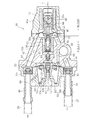
- FIG. 2 is a cross-sectional view showing details of the fuel pump 26.
- the casing of the fuel pump 26 includes a motor casing 41a, a pump casing 41b, and a regulator casing 41c, which are coupled to each other with bolts (not shown).
- a DC motor 42 (shown by a broken line) is housed in the motor casing 41 a as a drive source of the fuel pump 26, and a cam 43 is fixed to the output shaft 42 a of the DC motor 42, and is within the frame-shaped cam receiving member 44. The cam 43 rotates together with the output shaft 42a.
- a fixing member 45 is fitted and fixed to the distal end portion (left side in the figure) of the cam receiving member 44 from the pump casing 41 b side, and the center portion of the diaphragm 46 is sandwiched between the cam receiving member 44 and the fixing member 45. Yes.
- the outer peripheral portion of the diaphragm 46 is sandwiched between the motor casing 41a and the pump casing 41b, and a diaphragm chamber 47 is defined on the pump casing 41b side of the diaphragm 46.
- connection portions 48 and 49 are formed in the regulator casing 41c, and the supply hose 27 and the return hose 28 from the fuel tank 25 are connected to the connection portions 48 and 49, respectively.
- the connection portion 48 on the supply hose 27 side communicates with the inside of the diaphragm chamber 47 via a supply passage 50 formed in the pump casing 41b, and the supply passage 50 is a check that regulates the outflow of fuel from the inside of the diaphragm chamber 47.
- a valve 51 is provided.
- the connecting portion 49 on the return hose 28 side communicates with the inside of the diaphragm chamber 47 through a return passage 52 formed in the pump casing 41b, and the return passage 52 regulates the inflow of fuel into the diaphragm chamber 47.
- a check valve 53 is provided.
- the fuel from the fuel tank 25 flows into the diaphragm chamber 47 through the supply hose 27 and the supply passage 50.
- the fuel in the diaphragm chamber 47 is recovered to the fuel tank 25 side via the return passage 52 and the return hose 28, and such fuel transfer is repeated for each amplitude of the diaphragm 46. .
- a sleeve 55 is fitted and fixed to the pump casing 41b along the axis L so as to be continuous with the diaphragm chamber 47, and a plunger 56 is slidably disposed along the axis L in the sleeve 55 so as to be pressurized. 57 is defined.
- One end of the fixed member 45 is connected to the plunger 56, and the plunger 56 reciprocates between the suction side and the discharge side together with the fixed member 45. As a result, the reciprocation of the plunger 56 is synchronized with the amplitude of the diaphragm 46.
- a suction port 56 a is formed on the diaphragm chamber 47 side of the plunger 56 so as to communicate between the inside and the outside, and a check valve 58 for restricting the backflow of fuel into the plunger 56 is provided on the pressure chamber 57 side of the plunger 56. ing. At the position where the plunger 56 moves to the suction side and reaches the stroke end, the suction port 56a is exposed in the diaphragm chamber 47, and a part of the fuel in the diaphragm chamber 47 flows into the plunger 56 through the suction port 56a. Further, the check valve 58 flows into the pressurizing chamber 57 while being opened. The fuel that has flowed into the pressurizing chamber 57 is pressurized with the subsequent movement of the plunger 56 toward the discharge side, and such pressurization of the fuel is repeated each time the plunger 56 reciprocates.
- a discharge chamber 59 is formed in the pump casing 41 b so as to communicate with the pressurization chamber 57, and a check valve that restricts the backflow of fuel to the pressurization chamber 57 side between the pressurization chamber 57 and the discharge chamber 59. 60 is provided.
- the discharge chamber 59 communicates with a regulator chamber 62 formed in the regulator casing 41 c, and a valve body 63 is disposed in the regulator chamber 62.
- the valve body 63 has a cylindrical shape along the axis L, and a flange portion 63a is formed on the pump casing 41b side.
- a ring-shaped retainer 64 is fitted into the valve body 63 from the regulator casing 41c side.
- the center portion of the diaphragm 65 is sandwiched between the flange portion 63a of the valve body 63 and the retainer 64, and the outer peripheral portion of the diaphragm 65 is sandwiched between the pump casing 41b and the regulator casing 41c.
- the pressure regulation chamber 66 is defined on the pump casing 41b side of the diaphragm 65
- the relief chamber 67 is defined on the regulator casing 41c side.
- the pressure adjusting chamber 66 is connected to the injector 16 (shown in FIG. 1) via an injector passage 68, while the relief chamber 67 is connected to a connecting portion 49 on the return hose 28 side via a relief passage 69.
- the retainer 64 and the valve body 63 are urged toward the pump casing 41b by the relief spring 70 disposed in the regulator chamber 62, and the flange portion 63a of the valve body 63 abuts on the pump casing 41b side to contact the pressure adjusting chamber 66.
- the discharge chamber 59 is partitioned.
- the valve body 63 is provided with a relief hole 63b extending along the axis L, and a check valve 71 is provided in the relief hole 63b for regulating the outflow of fuel from the pressure regulating chamber 66 side to the relief chamber 67 side. ing.
- An adjusting bolt 72 is screwed into the regulator casing 41 c from the outside along the axis L, and the tip of the adjusting bolt 72 is inserted into the relief hole 63 b of the valve body 63 to face the check valve 71.
- a gap is formed between the inner periphery of the relief hole 63b and the outer periphery of the tip of the adjustment bolt 72.
- the operating state of the fuel pump 26 configured as described above will be described.
- the amplitude of the diaphragm 46 and the reciprocation of the plunger 56 are performed in synchronization.
- the fuel from the fuel tank 25 flows into the diaphragm chamber 47 through the supply hose 27 and the supply passage 50.
- the suction port 56a of the plunger 56 is exposed in the diaphragm chamber 47, a part of the fuel in the diaphragm chamber 47 flows into the plunger 56 through the suction port 56a and further opens the check valve 58. It flows into the pressurizing chamber 57 while being valved. That is, the fuel is substantially sent from the diaphragm chamber 47 side to the pressurizing chamber 57 side by the amplitude of the diaphragm 46 toward the suction side.
- the fuel in the pressurizing chamber 57 is pressurized, and the surplus fuel in the diaphragm chamber 47 is transferred to the return passage 52 and the return hose 28 along with the amplitude of the diaphragm 46 to the discharge side. Then, the fuel is recovered on the fuel tank 25 side.
- the check valve 60 is opened by pressurizing the fuel in the pressurizing chamber 57, the pressurized fuel is transferred to the discharge chamber 59, and the fuel pressure in the discharge chamber 59 (hereinafter referred to as fuel pressure) rises.
- fuel pressure the fuel pressure in the discharge chamber 59
- the fuel in the pressure regulation chamber 66 is discharged to the relief chamber 67 side through the relief hole 63 b of the valve body 63, and is further collected to the fuel tank 25 side together with surplus fuel from the diaphragm chamber 47 through the relief passage 69.
- the fuel pressure in the pressure adjusting chamber 66 is maintained at a set pressure that is determined in accordance with the urging force of the relief spring 70.
- the fuel adjusted to the set pressure in this way is supplied to the injector 16 through the injector passage 68, and the fuel is injected toward the intake port 9a of the engine 1 as the injector 16 is opened.
- the plunger 56 is reciprocated to pressurize the fuel, which is different from the conventional plunger type fuel pump, and therefore noise countermeasures are necessary.
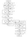
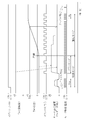
- FIG. 3 is a flowchart showing a fuel pump control routine executed by the ECU 31, and FIG. 4 is a time chart showing a control state from the engine start to the normal operation.
- FIG. 4 is a time chart showing a control state from the engine start to the normal operation.
- the control mode of the fuel pump 26 by the ECU 31 is roughly divided into a start mode for starting the engine 1 and an operation mode for continuing the operation of the engine 1 after the start is completed.
- the start mode is executed by a procedure of operating the fuel pump 26 again to start the engine 1 in accordance with cranking after the fuel pump 26 is operated as a preliminary fuel pressure control for recovering the fuel pressure lowered while the engine 1 is stopped. Is done.
- the operating speed of the fuel pump 26 in the start mode is suppressed as much as possible by reducing the duty ratio of the driving current to the DC motor 42, thereby reducing the operating noise of the fuel pump 26. Figured.
- the operation mode is shifted from the start mode to the operation mode, and the operation of the fuel pump 26 is continued.
- the operating speed of the fuel pump 26 is suppressed due to the decrease in the duty ratio, thereby reducing the operating noise. It is done.
- step S2 When the ignition switch of the vehicle is turned on and the power of the ECU 31 is turned on, the ECU 31 starts executing the routine of FIG. 3 at a predetermined control interval.
- step S2 a failure determination of the fuel pump 26 is executed, and then in step S4, a target duty ratio of the DC motor 42 for the start mode is calculated.
- the ECU 31 stores in advance a control map for calculating the target teat ratio for the start mode and the operation mode (storage means).
- the target duty ratio for the start mode is corrected based on a preset start base value (second noise countermeasure target value) based on a correction coefficient corresponding to the coolant temperature Tw and the battery voltage Vbtt read from the control map. (Correction means).
- the base value of the target duty ratio is set to the lowest possible value after ensuring the discharge amount of the fuel pump 26 required for engine start. Specifically, a value that takes a predetermined margin into the fuel injection amount of the injector 16 during engine start is set as a base value, and correction coefficients for the cooling water temperature Tw and the battery voltage Vbtt are added to the base value.
- the target duty ratio is obtained by multiplication.
- the correction coefficient of the battery voltage Vbtt is a well-known one for compensating for the voltage fluctuation, but the correction coefficient of the cooling water temperature Tw is specific to the fuel pump of the present embodiment provided with the diaphragm 46.
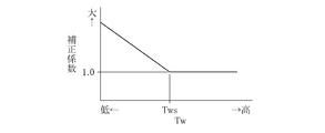
- FIG. 5 is an explanatory diagram showing a control map for setting the correction coefficient in accordance with the coolant temperature Tw. As shown in this figure, in the temperature range where the cooling water temperature Tw is less than the predetermined value Tws, the correction coefficient is set to increase as the cooling water temperature Tw decreases, and the target value is obtained by multiplying this correction coefficient by the base value. The ratio is corrected in the increasing direction as the cooling water temperature Tw decreases.
- Such setting characteristics of the target duty ratio take into consideration the characteristic change of the diaphragm 46 at low temperatures. That is, the rubber diaphragm 46 has a characteristic of being cured at a low temperature, and even if the DC motor 42 is driven at the same duty ratio, the reciprocation of the plunger 56 is prevented as the diaphragm 46 is cured, and the discharge of the fuel pump 26 is performed. The amount will decrease. In order to compensate for such a decrease in the discharge amount of the fuel pump 26 caused by the hardening of the diaphragm 46 at a low temperature, a correction coefficient based on the cooling water temperature Tw is set.
- the fuel pump 26 is disposed in the vicinity of the engine 1, and the temperature of the fuel pump 26 changes so as to correlate with the cooling water temperature Tw of the engine 1. Therefore, in this embodiment, the correction coefficient is set by regarding the cooling water temperature Tw detected by the existing water temperature sensor 35 as the temperature of the fuel pump 26.
- a temperature sensor may be provided in the fuel pump 26 and the number of correction fluids may be set based on the detected value (temperature detection means).
- the ECU 31 After calculating the target duty ratio for the start mode as described above, the ECU 31 proceeds to step S6 and calculates the pressure increase time Tup that is the duration of the preliminary fuel control.
- the boost time Tup is calculated by multiplying a preset base value by a correction coefficient. Based on a control map (not shown), the correction coefficient is set in the increasing direction as the cooling water temperature Tw decreases. By multiplying the correction coefficient by the base value, the boosting time Tup is set in the increasing direction as the cooling water temperature Tw decreases. (Correction means).
- Such a setting of the pressure increase time Tup is based on the knowledge that the fuel pressure is less likely to rise even when the fuel pump 26 is operated as the fuel is low temperature and the viscosity is high, and it takes time to recover the fuel pressure. Thus, the fuel pressure can be reliably recovered when the preliminary fuel control is completed.
- step S8 the ECU 31 drives the DC motor 42 based on the target duty ratio for the start mode set in step S4 to operate the fuel pump 26 (pump control means), and in the subsequent step S10, the fuel pump 26 It is determined whether or not the pressure increase time Tup has elapsed since the start of the operation. While the determination of No (No) is made in Step S10, the operation of the fuel pump 26 is continued in Step S8, and when the determination of Step S10 becomes Yes (Yes), the process proceeds to Step S12, and at this time, the reserve fuel The control is terminated and the operation of the fuel pump 26 is temporarily stopped.
- step S12 it is determined whether or not the engine 1 is cranking, and the process of step S12 is repeated while the determination is No. There is a case where the ignition switch is turned off without the engine start operation of the engine 1 being performed after the ignition switch is turned on. At this time, the power of the ECU 31 is shut off, so that this routine is executed without executing the subsequent processing. Will be terminated.
- step S14 the DC motor 42 is driven based on the target duty ratio for the start mode to operate the fuel pump 26, and in the subsequent step S16, it is determined whether or not the start is completed. Until the engine speed Ne during cranking exceeds a preset complete explosion determination value, it is considered that the engine 1 has not yet been started, and a determination of No is made in step S16 and the process returns to step S14. The processes of S14 and S16 are repeated.
- step S18 calculates the target duty ratio of the DC motor 42 for the operation mode.
- the target duty ratio for the operation mode is determined based on the engine rotation speed Ne and the throttle opening degree ⁇ th (the operation region of the engine 1 based on the control map stored in the ECU 31.
- the ECU 31 functions as an operation region detection unit when determining these. Is calculated by correcting a base value (first noise countermeasure target value) based on a correction coefficient corresponding to the coolant temperature Tw and the battery voltage Vbtt read from the control map (correction). means).
- the required discharge amount (in other words, the injection amount of the injector 16) to the fuel pump 26 varies greatly according to the operating region of the engine 1 (rotational speed Ne and throttle opening ⁇ th)
- the engine rotational speed Ne and throttle opening The base value and thus the target duty ratio are set so as to greatly depend on the degree ⁇ th, and in parallel with this, compensation according to the coolant temperature Tw and the battery voltage Vbtt is also performed.
- the base value of the target duty ratio is basically set in a decreasing direction as the engine speed Ne decreases, and is set in a decreasing direction as the throttle opening ⁇ th decreases. Therefore, for example, compared with the case where the DC motor 42 is driven at a constant duty ratio regardless of the operation region of the engine 1, the operating speed of the fuel pump 26 decreases as the rotation of the DC motor 42 decreases in the low rotation region and the low load region. As a result, the operating noise tends to be suppressed.
- a base value is set based on the control map to allow a certain amount of margin to the required discharge amount to the fuel pump 26, whereas in the idling region, the margin is reduced. The lowest possible base value is set from the control map.
- This setting characteristic of the control map is a result of considering the desire to reduce the operation sound of the fuel pump 26 particularly in the idle region.
- the correction coefficient for the cooling water temperature Tw is set based on the control map of FIG. 5 assuming that the diaphragm 46 is cured at a low temperature. Therefore, in the temperature range where the cooling water temperature Tw is lower than the predetermined value Tws, the correction coefficient is set in the increasing direction as the cooling water temperature Tw decreases.
- step S20 drives the fuel pump 26 by driving the DC motor 42 based on the target duty ratio for the operation mode set in step S18 (pump control means).
- step S22 it is determined whether or not the engine 1 has been stopped in response to the engine stop operation by the driver. When the determination is No, the process returns to step S18 to repeat the processes in steps S18 to S22.
- the operating range of the engine 1 always changes according to the vehicle running state and the driver's throttle operation.
- the target duty ratio corresponding to the engine 1 is calculated in step S18, and the DC motor 42 in step S22 reflects the calculation result. Is driven, and an appropriate amount of fuel is always supplied to the injector 16.
- step S24 determines whether or not a preset operation continuation time Tdv has elapsed since the engine stop. While the determination in step S24 is No, the processing in steps S18 to S24 is repeated. If the determination in step S24 is Yes, the routine is terminated after the failure determination of the fuel pump 26 is executed in step S26.
- the target duty ratio for the start mode applied to the driving of the DC motor 42 is calculated based on a base value set as low as possible while ensuring the discharge amount.
- the operating speed of the fuel pump 26 is suppressed. Since the operating sound of the fuel pump 26 is the most conspicuous because it is before the start of cranking, the operating sound is suppressed together with the operating speed of the fuel pump 26 in this way, so that the driver is aware of noise. It can be prevented beforehand.
- the fuel pump 26 starts to operate again.
- the target duty ratio for the start mode is applied to the driving of the DC motor 42, so that the operating noise is suppressed together with the operating speed of the fuel pump 26. Further, at this time, it is advantageous in terms of noise that the operating sound of the fuel pump 26 is mixed with the cranking sound generated by the engine 1.
- the target duty ratio for the operation mode is applied to drive the DC motor 42, and the operation of the fuel pump 26 is continued.
- the target duty ratio and thus the operating sound of the fuel pump 26 increase or decrease depending on the operating region of the engine 1, but if the engine sound decreases due to idling due to stopping due to a signal or the like, the target duty ratio decreases corresponding to the idle region.
- the driver since the operating sound of the fuel pump 26 is suppressed, the driver does not recognize the operating sound as noise.
- the target duty ratio is reduced to suppress the operating sound of the fuel pump 26. Yes. For this reason, it is possible to realize an effective noise countermeasure without causing any trouble in starting and operation of the engine 1, and to save power consumption by avoiding unnecessary driving of the DC motor 42 based on an excessive target duty ratio. Can do.
- the target duty ratio is corrected in the increasing direction based on the correction coefficient corresponding to the coolant temperature Tw in steps S4 and S8 of FIG.
- the fuel pump 26 is operated by the preliminary fuel pressure control.
- the DC motor 42 is driven based on the target duty ratio corrected to the increase side as compared with the restart after the warm-up is completed. Since the rotational speed of the DC motor 42 is increased, the discharge amount of the fuel pump 26 increases (increases to the discharge amount level after completion of warm-up), and as a result, the decrease in the discharge amount accompanying the hardening of the diaphragm 46 at the low temperature is compensated.
- this preliminary fuel pressure control can quickly recover the fuel pressure.
- the reduction in the discharge amount is compensated by the increase correction of the target duty ratio.
- a decrease in the discharge amount of the fuel pump 26 causes a decrease in the fuel injection amount from the injector 16 and thus a deterioration in engine startability, such a situation can be prevented and good engine startability can be realized.
- the decrease in the discharge amount of the fuel pump 26 is compensated for by the increase correction of the target duty ratio.
- the target duty ratio increase correction is gradually reduced, and when the cooling water temperature Tw reaches the predetermined value Tws, the rotation speed of the DC motor 42 is completely warmed up by stopping the increase correction.
- the control state is the same as when.
- the correction coefficient for the base value increases as the cooling water temperature Tw decreases when the cooling water temperature Tw is lower than the predetermined value Tws.
- the target duty ratio is increased and corrected by setting the direction. Therefore, it is possible to compensate for a decrease in the discharge amount of the fuel pump 26 due to the hardening of the diaphragm 46 at a low temperature, and to realize an appropriate discharge amount of the fuel pump 26 regardless of the temperature. Benefits can be gained.
- control device for the fuel pump 26 for the engine 1 mounted on the motorcycle is embodied, but the mounting target of the engine 1 is not limited to this.
- present invention may be embodied in a control device for a fuel pump for an engine mounted on a tricycle or a generator.
- the present invention is applied to the fuel pump 26 in which the diaphragm 46 and the plunger 56 are used together.
- the type of the fuel pump 26 is not limited to this.
- the present invention may be applied to a plunger type fuel pump that pressurizes and supplies fuel only by the plunger 56 without having the diaphragm 46.
- the correction processing of the target duty ratio according to the cooling water temperature Tw becomes unnecessary.
- the operation noise is suppressed by setting the target duty ratio of the fuel pump 26 in the decreasing direction during the preliminary fuel pressure control and the cranking in the start mode in addition to the idle operation of the engine 1 in the operation mode.
- the target duty ratio may be set as usual, and the target duty ratio may be set in a decreasing direction only during idle operation.
- the duty control is performed using the DC motor 42 as the drive source of the fuel pump 26.
- the present invention is not limited to this, and the motor type, control method, and the like may be changed as appropriate.
Landscapes
- Engineering & Computer Science (AREA)
- Chemical & Material Sciences (AREA)
- Combustion & Propulsion (AREA)
- Mechanical Engineering (AREA)
- General Engineering & Computer Science (AREA)
- Electrical Control Of Air Or Fuel Supplied To Internal-Combustion Engine (AREA)
- Fuel-Injection Apparatus (AREA)
Abstract
DCモータ42を駆動源としてプランジャ式の燃料ポンプ26を作動させて、所定圧に加圧した燃料をエンジン1のインジェクタ16に供給するように構成する。予めDCモータ42に供給すべき駆動電流の目標デューティ比をエンジン1の運転領域毎に設定すると共に、特にアイドル領域では他の運転領域に比較して目標デューティ比を騒音対策のために低い値に設定し、これらの目標デューティ比をECU31に記憶させておく。エンジン1の運転中には、その時々の運転領域に対応する目標デューティ比に基づきDCモータ42への駆動電流を制御して燃料ポンプ26を作動させ、アイドル領域では騒音対策のための目標デューティ比に基づく制御により燃料ポンプ26の作動速度を抑制して作動音の低減を図る。
Description
本発明は、燃料ポンプの制御装置に係り、特にモータを駆動源としてプランジャを往復動させて所定圧に加圧した燃料をエンジンのインジェクタに供給するプランジャ式の燃料ポンプの制御装置に関する。
従来から排ガス特性の改善や燃費向上等を目的として、エンジンへの燃料供給を電子制御化した燃料噴射装置が普及しており、その対象は四輪車のみならず、各種二輪車や発電機等にも及んでいる。この種の燃料噴射装置では、燃料タンク内の燃料を燃料ポンプにより汲み上げて所定圧に加圧し、加圧後の燃料をエンジンの吸気管に設けたインジェクタに供給し、エンジンの燃焼サイクルに同期してインジェクタを開閉制御して吸気管内に燃料を噴射するように構成されている。
このような燃料ポンプとしては、ハウジング内でインペラーを回転させて外周に設けた羽根溝の前後に生じた圧力差を連続的に増加させることにより燃料を加圧するウエスコ式燃料ポンプが普及している。しかしながら、例えば二輪車や発電機等に用いられる比較的小排気量のエンジンでは、燃料ポンプ自体にも小型化が要求されると共にポンプ駆動に要する消費電力の節減も望まれているため、それらの条件に適した特性を有するプランジャ式燃料ポンプが採用される場合がある。
この種のプランジャ式燃料ポンプは、シリンダ内にプランジャを摺動可能に配設して一方向に向けてリターンスプリングで付勢した上で、電磁コイルにより反対方向にプランジャを駆動するように構成されている。電磁コイルの周期的な励磁に応じてプランジャが往復動し、それに伴いシリンダ内で燃料が加圧されて間欠的に吐出される。しかしながら、プランジャ式燃料ポンプが発生する作動音は、その構造上プランジャの往復動に起因する断続的なものであり、しかも二輪車等の多くの場合に燃料ポンプがアウトタンク型として燃料タンク外に設置されることから、作動音が遮られることなく周囲に拡散してしまう。よって、従来のプランジャ式燃料ポンプは騒音面で改善の余地があった。
そこで、例えば特許文献1に記載されたプランジャ式燃料ポンプでは、電磁コイルの励磁中止によりプランジャがリターンスプリングの付勢力で一方向に復帰するまでの期間中に、スナバー回路により電磁コイルの励磁力を減衰させており、これによりプランジャが一方向に復帰するときの移動速度を低下させて騒音低減を図っている。
しかしながら、特許文献1の技術による騒音低減効果は電磁コイルの励磁力を減衰させることによって得られるものであり、必然的にモータ等の他の駆動源に対して応用できる対策ではない。従って、モータを駆動源としたプランジャ式燃料ポンプでは依然として騒音問題を抱えており、特にエンジン音が低下するアイドル運転時には燃料ポンプの作動音が際だってしまう。
例えば、この種の燃料ポンプを二輪車に適用した場合、エンジン音が高まる走行中には燃料ポンプの作動音がエンジン音に紛れ込むことから、その作動音を運転者が意識することはないが、信号待ち等による停車でアイドル運転によりエンジン音が低下すると、運転者は燃料ポンプの作動音を騒音として意識してしまう。よって、従来からモータを駆動源としたプランジャ式燃料ポンプに対する騒音対策が要望されていた。
例えば、この種の燃料ポンプを二輪車に適用した場合、エンジン音が高まる走行中には燃料ポンプの作動音がエンジン音に紛れ込むことから、その作動音を運転者が意識することはないが、信号待ち等による停車でアイドル運転によりエンジン音が低下すると、運転者は燃料ポンプの作動音を騒音として意識してしまう。よって、従来からモータを駆動源としたプランジャ式燃料ポンプに対する騒音対策が要望されていた。
本発明はこのような問題点を解決するためになされたもので、その目的とするところは、モータを駆動源としたプランジャ式燃料から発生する作動音を低減することができる燃料ポンプの制御装置を提供することにある。
上記の目的を達成するため、本発明の燃料ポンプの制御装置は、燃料タンク外に設置されるアウトタンク型として構成され、モータの駆動によりプランジャを往復動させて所定圧に加圧した燃料をエンジンのインジェクタに供給するプランジャ式の燃料ポンプと、エンジンの運転領域を検出する運転領域検出手段と、エンジンの運転領域毎に燃料ポンプのモータに供給すべき駆動電流の目標値を記憶し、アイドル領域に対しては他の運転領域に比較して低電流側に設定された第1の騒音対策目標値を記憶する記憶手段と、記憶手段に記憶された駆動電流の目標値に基づき燃料ポンプのモータへの駆動電流を制御して燃料ポンプを作動させ、運転領域検出手段によりエンジンのアイドル領域が検出されているときには、第1の騒音対策目標値に基づき駆動電流を制御して燃料ポンプの作動速度を抑制するポンプ制御手段とを具備したことを特徴とする。
このように構成した燃料ポンプの制御装置によれば、エンジンの運転中には記憶手段に記憶された駆動電流の目標値に基づき運転領域に対応して燃料ポンプのモータへの駆動電流が制御され、特にアイドル領域では第1の騒音対策目標値に基づく制御により燃料ポンプの作動速度が抑制される。結果として燃料ポンプの作動音が際だつアイドル運転時に限って駆動電流の目標値を低下させて燃料ポンプの作動音を抑制するため、エンジンの運転に全く支障を及ぼすことなく効果的に騒音対策がなされると共に、過剰な駆動電流の供給に基づく無駄なモータの駆動を回避して電力消費を節減可能となる。
その他の態様として、記憶手段が、エンジンの始動操作に先だちインジェクタへの燃圧を所定圧に回復させる予備燃圧制御のために低電流側に設定された第2の騒音対策目標値を記憶し、ポンプ制御手段が、エンジンのイグニションスイッチがON操作されたときに、予備燃圧制御として第2の騒音対策目標値に基づきモータへの駆動電流を制御して燃料ポンプを予め設定された昇圧時間に亘って作動させるように構成することが望ましい。
このように構成した場合には、エンジンの始動操作に先だち予備燃圧制御により燃料ポンプが作動してインジェクタへの燃圧の回復が図られるが、その際にも第2の騒音対策目標値に基づく駆動電流の制御により燃料ポンプの作動速度が抑制される。クランキング開始前であることから燃料ポンプの作動音が最も際だつ状況であるが、燃料ポンプの作動速度と共に作動音が抑制されることから、運転者が騒音を意識する事態が未然に防止される。
その他の態様として、ポンプ制御手段が、予備燃圧制御後にエンジンの始動操作として実行されるクラキング中においても、第2の騒音対策目標値に基づきモータへの駆動電流を制御するように構成することが望ましい。
このように構成した場合には、予備燃圧制御後のクラキング中にも第2の騒音対策目標値に基づく駆動電流の制御により燃料ポンプの作動速度が抑制されるため、それに伴って燃料ポンプの作動音が抑制される。
このように構成した場合には、予備燃圧制御後のクラキング中にも第2の騒音対策目標値に基づく駆動電流の制御により燃料ポンプの作動速度が抑制されるため、それに伴って燃料ポンプの作動音が抑制される。
その他の態様として、記憶手段が、モータに供給すべき駆動電流の目標値としてデューティ比を記憶し、ポンプ制御手段が、記憶手段に記憶されたデューティ比に基づきモータへの駆動電流を制御するように構成することが望ましい。
このように構成した場合には、デューティ比に基づきモータに駆動電流を供給して駆動するためモータの回転を容易に制御可能であると共に、モータを駆動する際の電力ロスが少ないことから電力消費を一層節減可能となる。
このように構成した場合には、デューティ比に基づきモータに駆動電流を供給して駆動するためモータの回転を容易に制御可能であると共に、モータを駆動する際の電力ロスが少ないことから電力消費を一層節減可能となる。
その他の態様として、燃料ポンプの温度を検出する温度検出手段と、温度検出手段により検出された燃料ポンプの温度が低温側のときには、記憶手段に記憶された第1の騒音対策目標値を高電流側に補正する補正手段とをさらに備え、燃料ポンプが、モータの駆動によりプランジャの往復動に同期してダイヤフラムを振幅させて、ダイヤフラムから送り出された燃料をプランジャで加圧してインジェクタに供給するように構成され、ポンプ制御手段が、エンジンがアイドル領域のときに補正手段による補正後の第1の騒音対策目標値に基づきモータへの駆動電流を制御するように構成することが望ましい。
このように構成した場合には、燃料ポンプの温度が低温側のときにはダイヤフラムが硬化してプランジャの往復動を妨げるが、このとき第1の騒音対策目標値が高電流側に補正されるため、アイドル運転時におけるダイヤフラムの硬化に起因する燃料ポンプの吐出量の低下が補償される。
このように構成した場合には、燃料ポンプの温度が低温側のときにはダイヤフラムが硬化してプランジャの往復動を妨げるが、このとき第1の騒音対策目標値が高電流側に補正されるため、アイドル運転時におけるダイヤフラムの硬化に起因する燃料ポンプの吐出量の低下が補償される。
その他の態様として、補正手段が、燃料ポンプの温度が低温側のときに第1の騒音対策目標値と共に第2の騒音対策目標値を高電流側に補正し、ポンプ制御手段が、予備燃圧制御のときに補正手段による補正後の第2の騒音対策目標値に基づきモータへの駆動電流を制御するように構成することが望ましい。
このように構成した場合には、第1の騒音対策目標値に加えて第2の騒音対策目標値も高電流側に補正されるため、予備燃圧制御時におけるダイヤフラムの硬化に起因する燃料ポンプの吐出量の低下が補償される。
このように構成した場合には、第1の騒音対策目標値に加えて第2の騒音対策目標値も高電流側に補正されるため、予備燃圧制御時におけるダイヤフラムの硬化に起因する燃料ポンプの吐出量の低下が補償される。
その他の態様として、補正手段が、温度検出手段により検出された燃料ポンプの温度が低温側のときに予備燃圧制御の昇圧時間を増加側に補正し、ポンプ制御手段が、補正手段による補正後の昇圧時間に基づき予備燃圧制御を実行するように構成することが望ましい。
このように構成した場合には、燃料が低温で粘性が高いときほど燃料ポンプを作動させても燃圧が上昇し難いが、このとき昇圧時間が増加側に補正されるため、予備燃料制御が終了した時点で燃圧が確実に回復する。
このように構成した場合には、燃料が低温で粘性が高いときほど燃料ポンプを作動させても燃圧が上昇し難いが、このとき昇圧時間が増加側に補正されるため、予備燃料制御が終了した時点で燃圧が確実に回復する。
本発明によれば、モータを駆動源としたプランジャ式燃料から発生する作動音を低減することができる。
以下、本発明を二輪車に搭載されるエンジン用の燃料ポンプの制御装置に具体化した一実施形態を説明する。
図1は本実施形態の燃料ポンプの制御装置を示すシステム構成図である。
本実施形態のエンジン1は、排気量50ccの4サイクル単気筒ガソリンエンジンとして構成されており、走行用動力源として二輪車に搭載されている。但し、エンジン1の仕様については、これに限定されるものではなく任意に変更可能である。但し、エンジン1の仕様については、これに限定されるものではなく任意に変更可能である。
図1は本実施形態の燃料ポンプの制御装置を示すシステム構成図である。
本実施形態のエンジン1は、排気量50ccの4サイクル単気筒ガソリンエンジンとして構成されており、走行用動力源として二輪車に搭載されている。但し、エンジン1の仕様については、これに限定されるものではなく任意に変更可能である。但し、エンジン1の仕様については、これに限定されるものではなく任意に変更可能である。
エンジン1のシリンダブロック2に形成されたシリンダ3内にはピストン4が摺動可能に配設され、ピストン4はコンロッド5を介してクランク軸6に連結されてピストン4の往復動に連動してクランク軸6が回転するようになっている。クランク軸6の後端(図示しない変速機側)にはフライホイール7が取り付けられ、フライホイール7の外周上の所定位置にはクランク角を検出するためのリラクタ7aが形成されている。
シリンダブロック2上に固定されたシリンダヘッド9には吸気ポート9a及び排気ポート9bが形成されると共に、先端を筒内に臨ませた姿勢で点火プラグ10が配設されている。吸気ポート9aに接続された吸気通路11には、上流側よりエアクリーナ12、運転者のスロットル操作に応じて開閉されるスロットルバルブ13、ISCV(アイドルスピードコントロールバルブ)14を備えたバイパス通路15、及び吸気ポート9aに向けて燃料を噴射するインジェクタ16が設けられている。また排気ポート9bに接続された排気通路17には、排ガスを浄化するための三元触媒18及び図示しない消音器が設けられている。
吸気ポート9aには吸気バルブ20が配設され、排気ポート9bには排気バルブ21が配設されている。これらの吸排気バルブ20,21はバルブスプリング22により閉弁側に付勢されると共に、シリンダヘッド9上でクランク軸6に同期して回転駆動される吸気カム軸23及び排気カム軸24により開弁される。これによりピストン4の往復動に同期した所定のタイミングで吸気バルブ20及び排気バルブ21が開閉し、吸気、圧縮、膨張、排気の4つの行程からなるエンジン1の燃焼サイクルがクランク角で720°CA毎に繰り返される。
上記インジェクタ16には、燃料タンク25内に貯留された燃料(ガソリン)が燃料ポンプ26により供給される。本実施形態の燃料ポンプ26はプランジャ式燃料ポンプの一種であり、その構成及び作動状態については後述するが、ダイヤフラムとプランジャとを併用することによりインジェクタ16の作動に必要な所定圧(例えば300MPa程度)の燃料を加圧して供給可能となっている。燃料ポンプ26はインジェクタ16と一体化され、供給ホース27及びリターンホース28を介してそれぞれ燃料タンク25に対して接続されている。
燃料ポンプ26が作動すると燃料タンク25内の燃料が供給ホース27を介して燃料ポンプ26内に導かれて所定圧に加圧され、加圧後の燃料がインジェクタ16に供給されると共に、余剰燃料がリターンホース28を介して燃料タンク25に回収される。これによりインジェクタ16には常に所定圧の燃料が供給され、インジェクタ16の開弁に応じて所定の噴射時期及び噴射量で吸気ポート9aに向けて燃料が噴射される。
エンジン1の運転中には、吸気行程でピストン4の下降に伴って発生した負圧によりエアクリーナ12を介して吸気通路11内に外気が吸入され、吸入空気はスロットルバルブ13の開度に応じて流量調整された後、インジェクタ16からの噴射燃料と混合しながら吸気バルブ20の開弁中にエンジン1の筒内に流入する。続く圧縮行程での圧縮を経て混合気は圧縮上死点の近傍で点火プラグ10により点火され、膨張行程中に燃焼してピストン4を介してクランク軸6に回転力を付与する。続く排気行程では燃焼後の排ガスが排気バルブ21の開弁中に筒内より排出され、排気通路17を流通しながら三元触媒18及び消音器を経て外部に排出される。
以上のエンジン1の燃焼サイクルは、ECU31(エンジン制御ユニット)の制御に基づき実行される。そのためにECU31の入力側には、上記フライホイール7に対向配置されてリラクタ7aに同期した信号を出力する電磁ピックアップ32、スロットルバルブ13の開度を検出するスロットルセンサ33、排気通路17に配設されてストイキ(理論空燃比)を中心とした排気空燃比の変動に応じて出力をステップ状に変動させるO2センサ34、エンジン1の冷却水温Twを検出する水温センサ35(温度検出手段)等の各種センサ類が接続されている。また、ECU31の出力側には、上記ISCV14、インジェクタ16、燃料ポンプ26、点火プラグ10を駆動するイグナイタ36等の各種デバイス類が接続されている。
これらのセンサ情報に基づきECU31は、インジェクタ16を駆動するための燃料噴射制御、点火プラグ10を駆動するための点火時期制御、燃料ポンプ26を駆動するためのポンプ制御等の各種制御を実行してエンジン1を運転する。
例えばECU31は燃料噴射制御として、電磁ピックアップ32の信号から算出したエンジン回転速度Ne及びスロットルセンサ33により検出されたスロットル開度θth等に基づき目標燃料噴射量を決定し、吸気行程の所定タイミングでインジェクタ16を駆動して燃料噴射を実行する。
例えばECU31は燃料噴射制御として、電磁ピックアップ32の信号から算出したエンジン回転速度Ne及びスロットルセンサ33により検出されたスロットル開度θth等に基づき目標燃料噴射量を決定し、吸気行程の所定タイミングでインジェクタ16を駆動して燃料噴射を実行する。
またECU31は点火時期制御として、エンジン回転速度Ne及びスロットル開度θth等に基づき目標点火時期を決定する一方、電磁ピックアップ32の信号を波形整形してリラクタ7a(換言するとクランク角)に同期した矩形波状のクランク角信号を生成する。そして、クランク角信号に基づき目標点火時期に対応するタイミングを特定し、イグナイタ36を駆動して点火プラグ10を点火させる。
またECU31はポンプ制御として、エンジン1の運転中に燃料ポンプ26を駆動して所定圧に加圧した燃料をインジェクタ16に供給する。
またECU31はポンプ制御として、エンジン1の運転中に燃料ポンプ26を駆動して所定圧に加圧した燃料をインジェクタ16に供給する。
しかしながら、本実施形態の燃料ポンプ26はプランジャ式燃料ポンプの構成を備えるため、[発明が解決しようとする課題]で述べた従来からのプランジャ式燃料ポンプと同じく騒音対策を必要とする。そこで本実施形態では、エンジン1の運転状態等の諸条件に応じて燃料ポンプ26の駆動源であるDCモータ42(図2に示す)の回転速度を可変制御することにより、燃料ポンプ26の騒音低減を図っている。DCモータ42の駆動電流の目標値としてはデューティ比を適用し、その目標デューティ比に基づきDCモータ42を駆動している。その詳細を以下に述べるが、それに先だって、まず燃料ポンプ26の構成について説明する。
図2は燃料ポンプ26の詳細を示す断面図である。
燃料ポンプ26のケーシングは、モータケーシング41a、ポンプケーシング41b及びレギュレータケーシング41cから構成され、図示しないボルトで互いに結合されている。モータケーシング41a内には燃料ポンプ26の駆動源としてDCモータ42(破線で示す)が収容され、DCモータ42の出力軸42aにはカム43が固定されて枠状のカム受け部材44の中で出力軸42aと共にカム43が回転するようになっている。カム受け部材44の先端部(図中の左側)にはポンプケーシング41b側から固定部材45が嵌合固定され、カム受け部材44と固定部材45との間にダイヤフラム46の中心部が挟持されている。ダイヤフラム46の外周部はモータケーシング41aとポンプケーシング41bとの間に挟持され、ダイヤフラム46のポンプケーシング41b側にダイヤフラム室47が画成されている。
燃料ポンプ26のケーシングは、モータケーシング41a、ポンプケーシング41b及びレギュレータケーシング41cから構成され、図示しないボルトで互いに結合されている。モータケーシング41a内には燃料ポンプ26の駆動源としてDCモータ42(破線で示す)が収容され、DCモータ42の出力軸42aにはカム43が固定されて枠状のカム受け部材44の中で出力軸42aと共にカム43が回転するようになっている。カム受け部材44の先端部(図中の左側)にはポンプケーシング41b側から固定部材45が嵌合固定され、カム受け部材44と固定部材45との間にダイヤフラム46の中心部が挟持されている。ダイヤフラム46の外周部はモータケーシング41aとポンプケーシング41bとの間に挟持され、ダイヤフラム46のポンプケーシング41b側にダイヤフラム室47が画成されている。
レギュレータケーシング41cには一対の接続部48,49が形成され、これらの接続部48,49に上記燃料タンク25からの供給ホース27及びリターンホース28がそれぞれ接続されている。供給ホース27側の接続部48は、ポンプケーシング41bに形成された供給通路50を介してダイヤフラム室47内と連通し、供給通路50にはダイヤフラム室47内からの燃料の流出を規制する逆止弁51が設けられている。また、リターンホース28側の接続部49は、ポンプケーシング41bに形成されたリターン通路52を介してダイヤフラム室47内と連通し、リターン通路52にはダイヤフラム室47内への燃料の流入を規制する逆止弁53が設けられている。
従って、DCモータ42の出力軸42aと共にカム43が回転すると、その回転運動がカム受け部材44によって図中の左右方向への直線運動(以下、この方向を軸線L方向と称する)に変換される。この直線運動がダイヤフラム46に伝達され、結果としてダイヤフラム46が軸線L方向に沿って図中の右方(以下、吸込側と称する)と左方(以下、吐出側と称する)との間で交互に振幅する。そして、ダイヤフラム46が吸込側に振幅したときには、燃料タンク25からの燃料が供給ホース27及び供給通路50を経てダイヤフラム室47内に流入する。またダイヤフラム46が吐出側に振幅したときには、ダイヤフラム室47内の燃料がリターン通路52及びリターンホース28を経て燃料タンク25側に回収され、このような燃料の移送がダイヤフラム46の振幅毎に繰り返される。
ポンプケーシング41bにはダイヤフラム室47と連続するように軸線Lに沿ってスリーブ55が嵌合固定され、スリーブ55内にはプランジャ56が軸線Lに沿って摺動可能に配設されて加圧室57を画成している。プランジャ56には固定部材45の一端が連結され、固定部材45と共にプランジャ56が吸込側と吐出側との間で往復動する。結果として、プランジャ56の往復動はダイヤフラム46の振幅と同期したものとなる。
プランジャ56のダイヤフラム室47側には内外を連通するように吸込口56aが形成され、プランジャ56の加圧室57側にはプランジャ56内への燃料の逆流を規制する逆止弁58が設けられている。プランジャ56が吸込側に移動してストローク端に到達した位置では吸込口56aがダイヤフラム室47内に露出し、ダイヤフラム室47内の燃料の一部が吸込口56aを経てプランジャ56内に流入し、さらに逆止弁58を開弁させながら加圧室57内に流入する。この加圧室57内に流入した燃料は、その後のプランジャ56の吐出側への移動に伴って加圧され、このような燃料の加圧がプランジャ56の往復動毎に繰り返される。
ポンプケーシング41bには加圧室57と連通するように吐出室59が形成され、加圧室57と吐出室59との間には加圧室57側への燃料の逆流を規制する逆止弁60が設けられている。吐出室59はレギュレータケーシング41cに形成されたレギュレータ室62と連通し、レギュレータ室62内には弁体63が配設されている。弁体63は軸線Lに沿った筒状をなしてポンプケーシング41b側にフランジ部63aが形成され、弁体63にはレギュレータケーシング41c側よりリング状のリテーナ64が嵌め込まれている。
弁体63のフランジ部63aとリテーナ64との間にはダイヤフラム65の中心部が挟持され、ダイヤフラム65の外周部はポンプケーシング41bとレギュレータケーシング41cとの間に挟持されている。これによりダイヤフラム65のポンプケーシング41b側に圧力調整室66が画成され、レギュレータケーシング41c側にリリーフ室67が画成されている。圧力調整室66はインジェクタ通路68を介して上記インジェクタ16(図1に示す)に接続され、一方、リリーフ室67はリリーフ通路69を介して上記リターンホース28側の接続部49に接続されている。
レギュレータ室62内に配設されたリリーフスプリング70によりリテーナ64及び弁体63はポンプケーシング41b側に付勢され、弁体63のフランジ部63aがポンプケーシング41b側に当接して圧力調整室66と吐出室59とを区画している。弁体63には軸線Lに沿ってリリーフ孔63bが貫設され、このリリーフ孔63b内には圧力調整室66側からリリーフ室67側への燃料の流出を規制する逆止弁71が設けられている。レギュレータケーシング41cには軸線Lに沿って外部から調整ボルト72が螺合し、調整ボルト72の先端は弁体63のリリーフ孔63b内に挿入されて逆止弁71と対峙している。図示はしないがリリーフ孔63bの内周と調整ボルト72の先端の外周との間には間隙が形成され、逆止弁71の開弁時には圧力調整室66側からリリーフ室67側に燃料が排出されるようになっている。
次に、以上のように構成された燃料ポンプ26の作動状態を説明する。
DCモータ42の駆動によるカム43の回転に伴って、ダイヤフラム46の振幅とプランジャ56の往復動とが同期して行われる。ダイヤフラム46が吸込側に振幅すると、燃料タンク25からの燃料が供給ホース27及び供給通路50を経てダイヤフラム室47内に流入する。このときにはプランジャ56の吸込口56aがダイヤフラム室47内に露出していることから、ダイヤフラム室47内の燃料の一部が吸込口56aを経てプランジャ56内に流入し、さらに逆止弁58を開弁させながら加圧室57内に流入する。即ち、ダイヤフラム46の吸込側への振幅により、実質的にダイヤフラム室47側から加圧室57側に燃料が送り出されたことになる。
DCモータ42の駆動によるカム43の回転に伴って、ダイヤフラム46の振幅とプランジャ56の往復動とが同期して行われる。ダイヤフラム46が吸込側に振幅すると、燃料タンク25からの燃料が供給ホース27及び供給通路50を経てダイヤフラム室47内に流入する。このときにはプランジャ56の吸込口56aがダイヤフラム室47内に露出していることから、ダイヤフラム室47内の燃料の一部が吸込口56aを経てプランジャ56内に流入し、さらに逆止弁58を開弁させながら加圧室57内に流入する。即ち、ダイヤフラム46の吸込側への振幅により、実質的にダイヤフラム室47側から加圧室57側に燃料が送り出されたことになる。
その後にプランジャ56が吐出側に移動すると加圧室57内の燃料が加圧されると共に、ダイヤフラム46の吐出側への振幅に伴ってダイヤフラム室47内の余剰燃料がリターン通路52及びリターンホース28を経て燃料タンク25側に回収される。加圧室57内での燃料の加圧により逆止弁60が開弁されて加圧後の燃料が吐出室59に移送され、吐出室59内の燃料圧力(以下、燃圧と称する)の上昇によりリリーフスプリング70を撓ませながら弁体63がレギュレータケーシング41c側に移動し、吐出室59の燃料が圧力調整室66内に移送される。
そして、レギュレータケーシング41c側に弁体63が移動することにより、内部の逆止弁71が調整ボルト72の先端に押圧されて開弁する。よって、圧力調整室66内の燃料が弁体63のリリーフ孔63bを経てリリーフ室67側に排出され、さらにリリーフ通路69を経てダイヤフラム室47からの余剰燃料と共に燃料タンク25側に回収される。結果として圧力調整室66内の燃圧は、リリーフスプリング70の付勢力に対応して定まる設定圧に保たれる。そして、このようにして設定圧に調整された燃料がインジェクタ通路68を経てインジェクタ16に供給され、インジェクタ16の開弁に伴ってエンジン1の吸気ポート9aに向けて燃料が噴射される。
燃料ポンプ26の作動状態についての以上の説明から明らかなようにプランジャ56を往復動させて燃料を加圧する点では従来からのプランジャ式燃料ポンプと相違なく、それ故に騒音対策が必要なのである。
燃料ポンプ26の作動状態についての以上の説明から明らかなようにプランジャ56を往復動させて燃料を加圧する点では従来からのプランジャ式燃料ポンプと相違なく、それ故に騒音対策が必要なのである。
次いで、このような騒音対策のためにECU31がポンプ制御として実行する処理について述べる。
図3はECU31が実行する燃料ポンプ制御ルーチンを示すフローチャート、図4はエンジン始動から通常の運転に移行するまでの制御状況を示すタイムチャートである。
具体的なECU31の処理の説明に先立ち、エンジン1の始動操作から通常のエンジン1の運転に移行するまでのECU31によるポンプ制御の概要について、図4のタイムチャートに従って説明する。
図3はECU31が実行する燃料ポンプ制御ルーチンを示すフローチャート、図4はエンジン始動から通常の運転に移行するまでの制御状況を示すタイムチャートである。
具体的なECU31の処理の説明に先立ち、エンジン1の始動操作から通常のエンジン1の運転に移行するまでのECU31によるポンプ制御の概要について、図4のタイムチャートに従って説明する。
ECU31による燃料ポンプ26の制御モードは、エンジン1を始動するための始動モードと始動完了後にエンジン1の運転を継続するための運転モードとに大別される。始動モードは、エンジン1の停止中に低下した燃圧を回復させる予備燃圧制御として燃料ポンプ26を作動させた後に、クランキングに応じてエンジン1を始動すべく再び燃料ポンプ26を作動させる手順で実行される。後述するように、この始動モード中の燃料ポンプ26は、DCモータ42への駆動電流のデューティ比を低下させることで可能な限り作動速度を抑制され、これにより燃料ポンプ26の作動音の低減が図られる。
エンジン1の始動完了後には始動モードから運転モードに移行し、燃料ポンプ26の作動が継続される。後述するように、この運転モード中においても、燃料ポンプ26の作動音が際だつエンジン1のアイドル運転中には、デューティ比の低下により燃料ポンプ26の作動速度が抑制されて作動音の低減が図られる。
エンジン1の始動完了後には始動モードから運転モードに移行し、燃料ポンプ26の作動が継続される。後述するように、この運転モード中においても、燃料ポンプ26の作動音が際だつエンジン1のアイドル運転中には、デューティ比の低下により燃料ポンプ26の作動速度が抑制されて作動音の低減が図られる。
車両のイグニションスイッチがON操作されてECU31の電源が投入されると、ECU31は図3のルーチンを所定の制御インターバルで実行し始める。まず、ステップS2で燃料ポンプ26のフェイル判定を実行し、続いてステップS4で始動モード用のDCモータ42の目標デューティ比を算出する。この算出処理のためにECU31には、始動モード用及び運転モード用の目標ティーティ比を算出するための制御マップが予め記憶されている(記憶手段)。
始動モード用の目標デューティ比は、予め設定された始動用のベース値(第2の騒音対策目標値)を、制御マップから読み出した冷却水温Tw及びバッテリ電圧Vbttに対応する補正係数に基づき補正することにより算出される(補正手段)。目標デューティ比のベース値は、エンジン始動に要求される燃料ポンプ26の吐出量を確保した上で、可能な限り低い値に設定されている。具体的には、エンジン始動中のインジェクタ16の燃料噴射量に対して所定の余裕分を加味した値がベース値として設定されており、そのベース値に冷却水温Tw及びバッテリ電圧Vbttの補正係数を乗算して目標デューティ比が求められる。
バッテリ電圧Vbttの補正係数は、電圧変動を補償するための周知のものであるが、冷却水温Twの補正係数に関しては、ダイヤフラム46を備えた本実施形態の燃料ポンプ特有のものである。
図5は冷却水温Twに応じて補正係数を設定するための制御マップを示す説明図である。この図に示すように、冷却水温Twが所定値Tws未満の温度域では、冷却水温Twが低下するほど補正係数が増加方向に設定され、この補正係数がベース値に乗算されることにより目標デューティ比は冷却水温Twが低下するほど増加方向に補正される。
図5は冷却水温Twに応じて補正係数を設定するための制御マップを示す説明図である。この図に示すように、冷却水温Twが所定値Tws未満の温度域では、冷却水温Twが低下するほど補正係数が増加方向に設定され、この補正係数がベース値に乗算されることにより目標デューティ比は冷却水温Twが低下するほど増加方向に補正される。
このような目標デューティ比の設定特性は、低温時のダイヤフラム46の特性変化を考慮したものである。即ち、ゴム製のダイヤフラム46は低温時に硬化する特性を有し、同一デューティ比でDCモータ42を駆動したとしても、ダイヤフラム46が硬化するほどプランジャ56の往復動が妨げられて燃料ポンプ26の吐出量が低下してしまう。このような低温時のダイヤフラム46の硬化に起因する燃料ポンプ26の吐出量の低下を補償するために、冷却水温Twに基づく補正係数が設定されているのである。
二輪車ではエンジン1の近接位置に燃料ポンプ26が配設され、エンジン1の冷却水温Twに相関するように燃料ポンプ26の温度が変化する。このため本実施形態では、既存の水温センサ35により検出された冷却水温Twを燃料ポンプ26の温度と見なして補正係数を設定している。但し、本来はダイヤフラム46が内蔵された燃料ポンプ26自体の温度を用いることが望ましいことから、燃料ポンプ26に温度センサを設けてその検出値に基づき補正液数を設定してもよい(温度検出手段)。
以上のようにして始動モード用の目標デューティ比を算出した後に、ECU31はステップS6に移行して予備燃料制御の継続時間である昇圧時間Tupを算出する。昇圧時間Tupは予め設定されたベース値に補正係数を乗算して算出される。図示しない制御マップに基づき、冷却水温Twが低下するほど補正係数が増加方向に設定され、この補正係数がベース値に乗算されることにより昇圧時間Tupは冷却水温Twが低下するほど増加方向に設定される(補正手段)。このような昇圧時間Tupの設定は、燃料が低温で粘性が高いときほど燃料ポンプ26を作動させても燃圧が上昇し難く、燃圧の回復に時間を要するとの知見に基づくものであり、これにより予備燃料制御が終了した時点で燃圧を確実に回復させることができる。
その後、ECU31はステップS8で、上記ステップS4で設定した始動モード用の目標デューティ比に基づきDCモータ42を駆動して燃料ポンプ26を作動させ(ポンプ制御手段)、続くステップS10で、燃料ポンプ26の作動開始から昇圧時間Tupが経過したか否かを判定する。ステップS10でNo(否定)の判定を下している間はステップS8で燃料ポンプ26の作動を継続し、ステップS10の判定がYes(肯定)になるとステップS12に移行し、この時点で予備燃料制御が終了して燃料ポンプ26の作動が一旦中止される。
続くステップS12ではエンジン1がクランキング中であるか否かを判定し、判定がNoの間はステップS12の処理を繰り返す。イグニションスイッチのON操作後にエンジン1のエンジンスタート操作が行われることなくイグニションスイッチがOFF操作される場合もあり、このときにはECU31の電源が遮断されるため、その後の処理を実行することなく本ルーチンが終了されることになる。
通常の場合には、イグニションスイッチのON操作後に運転者によりエンジンスタート操作が行われてエンジン1のクランキングが開始されるため、ECU31はステップS12でYesの判定を下してステップS14に移行する。ステップS14では始動モード用の目標デューティ比に基づきDCモータ42を駆動して燃料ポンプ26を作動させ、続くステップS16で始動完了か否かを判定する。クランキング中のエンジン回転速度Neが予め設定された完爆判定値を超えるまでは未だエンジン1の始動が完了していないと見なし、ステップS16でNoの判定を下してステップS14に戻り、ステップS14,16の処理を繰り返す。
そして、エンジン回転速度Neが完爆判定値を超えると、エンジン1の始動が完了したとしてステップS16からステップS18に移行する。この時点でECU31は始動モードから運転モードに移行し、ステップS18では運転モード用のDCモータ42の目標デューティ比を算出する。運転モード用の目標デューティ比は、ECU31に記憶された制御マップに基づきエンジン回転速度Ne及びスロットル開度θth(エンジン1の運転領域であり、これらを判定するときのECU31が運転領域検出手段として機能する)からベース値(第1の騒音対策目標値)を算出し、そのベース値を制御マップから読み出した冷却水温Tw及びバッテリ電圧Vbttに対応する補正係数に基づき補正することにより算出される(補正手段)。
エンジン1の運転領域(回転速度Ne・スロットル開度θth)に応じて燃料ポンプ26への要求吐出量(換言するとインジェクタ16の噴射量)が大幅に変化することから、エンジン回転速度Ne及びスロットル開度θthに大きく依存するようにベース値、ひいては目標デューティ比が設定され、これと並行して冷却水温Twやバッテリ電圧Vbttに応じた補償も行われることになる。
目標デューティ比のベース値は、基本的にエンジン回転速度Neが低下するほど低下方向に設定されると共に、スロットル開度θthが低下するほど低下方向に設定される。従って、例えばエンジン1の運転領域に関係なく一定のデューティ比でDCモータ42を駆動した場合に比較すると、低回転域や低負荷域ではDCモータ42の回転低下と共に燃料ポンプ26の作動速度が低下してその作動音が抑制される傾向となる。そして、アイドル領域以外の運転領域では、燃料ポンプ26への要求吐出量に対してある程度大きな余裕分を見込んだベース値が制御マップに基づき設定されるのに対し、アイドル領域では余裕分を縮小して可能な限り低い値のベース値が制御マップから設定されるようになっている。
この制御マップの設定特性は、特にアイドル領域で燃料ポンプ26の作動音を低減したいという要望を考慮した結果である。加えて、アイドル領域以外の運転領域では、常に急変するインジェクタ16の噴射量を確実にまかなえるだけの余裕分を燃料ポンプ26の吐出量として確保しておく必要があるのに対し、インジェクタ16の噴射量がほとんど変化しないアイドル領域では吐出量の余裕分をさらに縮小する余地があるとの知見に基づき、燃料ポンプ26の作動音の抑制を優先した結果でもある。
一方、冷却水温Twの補正係数に関しては、低温時のダイヤフラム46の硬化を想定した図5の制御マップに基づき設定される。従って、冷却水温Twが所定値Tws未満の温度域では、冷却水温Twが低下するほど補正係数が増加方向に設定される。
一方、冷却水温Twの補正係数に関しては、低温時のダイヤフラム46の硬化を想定した図5の制御マップに基づき設定される。従って、冷却水温Twが所定値Tws未満の温度域では、冷却水温Twが低下するほど補正係数が増加方向に設定される。
その後、ECU31はステップS20に移行し、ステップS18で設定した運転モード用の目標デューティ比に基づきDCモータ42を駆動して燃料ポンプ26を作動させる(ポンプ制御手段)。続くステップS22では運転者によるエンジンストップ操作に応じてエンジン1が停止されたか否かを判定し、判定がNoのときにはステップS18に戻ってステップS18~22の処理を繰り返す。車両の走行状態や運転者のスロットル操作に応じてエンジン1の運転領域は常に変化するが、それに応じた目標デューティ比がステップS18で算出され、その算出結果を反映してステップS22でDCモータ42が駆動されて、常に適正量の燃料がインジェクタ16に供給される。
そして、エンジン停止によりステップS22でYesの判定を下すと、ステップS24に移行してエンジン停止から予め設定された運転継続時間Tdvが経過したか否かを判定する。ステップS24の判定がNoの間はステップS18~24の処理を繰り返し、ステップS24の判定がYesになると、ステップS26で燃料ポンプ26のフェイル判定を実行した後にルーチンを終了する。
次に、以上のECU31の処理に基づく燃料ポンプ26の制御状況を図4のタイムチャートに従って説明する。
まず、暖機完了後のエンジン(Tw≧Tws)を再始動する場合について述べる。この場合には、図3のステップS4,8で冷却水温Twに応じた補正係数に基づく目標デューティ比の増加補正は実施されない。
車両のイグニションスイッチがON操作されると、ECU31により始動モードが開始され、予備燃圧制御により昇圧時間Tupに亘って燃料ポンプ26の作動が継続されて燃圧の回復が図られる。このときDCモータ42の駆動に適用される始動モード用の目標デューティ比は、吐出量を確保した上で可能な限り低く設定されたベース値に基づき算出されるため、DCモータ42の回転速度、ひいては燃料ポンプ26の作動速度が抑制される。クランキング開始前であることから燃料ポンプ26の作動音が最も際だつ状況であるが、このように燃料ポンプ26の作動速度と共に作動音が抑制されることから、運転者が騒音を意識する事態を未然に防止できる。
まず、暖機完了後のエンジン(Tw≧Tws)を再始動する場合について述べる。この場合には、図3のステップS4,8で冷却水温Twに応じた補正係数に基づく目標デューティ比の増加補正は実施されない。
車両のイグニションスイッチがON操作されると、ECU31により始動モードが開始され、予備燃圧制御により昇圧時間Tupに亘って燃料ポンプ26の作動が継続されて燃圧の回復が図られる。このときDCモータ42の駆動に適用される始動モード用の目標デューティ比は、吐出量を確保した上で可能な限り低く設定されたベース値に基づき算出されるため、DCモータ42の回転速度、ひいては燃料ポンプ26の作動速度が抑制される。クランキング開始前であることから燃料ポンプ26の作動音が最も際だつ状況であるが、このように燃料ポンプ26の作動速度と共に作動音が抑制されることから、運転者が騒音を意識する事態を未然に防止できる。
その後、運転者のエンジンスタート操作によりエンジン1のクランキングが開始されると、燃料ポンプ26は再び作動を開始する。このときにも始動モード用の目標デューティ比がDCモータ42の駆動に適用されるため、燃料ポンプ26の作動速度と共に作動音が抑制される。さらに、このときにはエンジン1が発するクランキング音に燃料ポンプ26の作動音が紛れることも騒音面で有利に働く。
クラキングによりエンジン1の始動が完了すると、DCモータ42の駆動には運転モード用の目標デューティ比が適用され、引き続き燃料ポンプ26の作動が継続される。エンジン1の運転領域に応じて目標デューティ比、ひいては燃料ポンプ26の作動音は増減するが、信号待ち等による停車でアイドル運転によりエンジン音が低下すると、アイドル領域に対応して目標デューティ比が低下して燃料ポンプ26の作動音が抑制されることから、その作動音を運転者が騒音として意識することはない。
このように燃料ポンプ26の作動音が際だつ状況(始動モードでのエンジン始動時、運転モードでのアイドル運転時)に限って、目標デューティ比を低下させて燃料ポンプ26の作動音を抑制している。このため、エンジン1の始動や運転に何ら支障を及ぼすことなく効果的な騒音対策を実現できると共に、過剰な目標デューティ比に基づく無駄なDCモータ42の駆動を回避して電力消費を節減することができる。
次に、冷態時のエンジン(Tw<Tws)を始動する場合について述べる。この場合には、図3のステップS4,8で冷却水温Twに応じた補正係数に基づき目標デューティ比が増加方向に補正される。
始動モードが開始されると予備燃圧制御により燃料ポンプ26が作動される。このときには、上記暖機完了後の再始動に比較して増加側に補正された目標デューティ比に基づきDCモータ42が駆動される。DCモータ42の回転速度が高められるため燃料ポンプ26の吐出量が増加(暖機完了後の吐出量レベルまで増加)し、結果として低温時のダイヤフラム46の硬化に伴う吐出量の低下が補償されて、この予備燃圧制御では迅速に燃圧を回復できる。
始動モードが開始されると予備燃圧制御により燃料ポンプ26が作動される。このときには、上記暖機完了後の再始動に比較して増加側に補正された目標デューティ比に基づきDCモータ42が駆動される。DCモータ42の回転速度が高められるため燃料ポンプ26の吐出量が増加(暖機完了後の吐出量レベルまで増加)し、結果として低温時のダイヤフラム46の硬化に伴う吐出量の低下が補償されて、この予備燃圧制御では迅速に燃圧を回復できる。
続くエンジン1のクランキング時においても、目標デューティ比の増加補正により吐出量の低下が補償される。燃料ポンプ26の吐出量の低下はインジェクタ16からの燃料噴射量の低下、ひいてはエンジン始動性の悪化の要因になるが、このような事態を防止して良好なエンジン始動性を実現できる。
さらにエンジン1の始動完了により運転モードに移行した後にも、目標デューティ比の増加補正により燃料ポンプ26の吐出量の低下が補償される。所期の吐出量が確保されることによりインジェクタ16の噴射量を高精度に制御できることから、二輪車のドライバビリティを向上することができる。そして、冷却水温Twの上昇に伴って目標デューティ比の増加補正は段階的に縮小され、冷却水温Twが所定値Twsに到達した時点では増加補正の中止によりDCモータ42の回転速度は暖機完了時と同様の制御状態となる。
さらにエンジン1の始動完了により運転モードに移行した後にも、目標デューティ比の増加補正により燃料ポンプ26の吐出量の低下が補償される。所期の吐出量が確保されることによりインジェクタ16の噴射量を高精度に制御できることから、二輪車のドライバビリティを向上することができる。そして、冷却水温Twの上昇に伴って目標デューティ比の増加補正は段階的に縮小され、冷却水温Twが所定値Twsに到達した時点では増加補正の中止によりDCモータ42の回転速度は暖機完了時と同様の制御状態となる。
以上のように始動モード(予備燃圧制御及びクランキング時)と運転モードとの何れにおいても、冷却水温Twが所定値Tws未満の低温時には、冷却水温Twが低下するほどベース値に対する補正係数を増加方向に設定して目標デューティ比を増加補正している。よって、低温時のダイヤフラム46の硬化に伴う燃料ポンプ26の吐出量の低下を補償して、温度に関わらず所期の適切な燃料ポンプ26の吐出量を実現でき、もってそれぞれの状況に応じた利点を得ることができる。
以上で実施形態の説明を終えるが、本発明の態様はこの実施形態に限定されるものではない。例えば上記実施形態では、二輪車に搭載されるエンジン1用の燃料ポンプ26の制御装置に具体化したが、エンジン1の搭載対象はこれに限るものではない。例えば三輪車や発電機に搭載されるエンジン用の燃料ポンプの制御装置に具体化してもよい。
また上記実施形態では、ダイヤフラム46とプランジャ56とを併用した燃料ポンプ26に適用したが、燃料ポンプ26の形式はこれに限るものではない。例えばダイヤフラム46を有することなくプランジャ56のみにより燃料を加圧・供給するプランジャ式燃料ポンプに適用してもよい。無論、この場合には低温時のダイヤフラム46の硬化対策として、冷却水温Twに応じた目標デューティ比の補正処理は不要となる。
また上記実施形態では、運転モードでのエンジン1のアイドル運転時に加えて、始動モードの予備燃圧制御及びクランキング時にも燃料ポンプ26の目標デューティ比を低下方向に設定して作動音を抑制したが、始動モードでは通常通りに目標デューティ比を設定し、アイドル運転時のみに目標デューティ比を低下方向に設定してもよい。
また上記実施形態では、燃料ポンプ26の駆動源としてDCモータ42を用いてデューティ制御したが、これに限るものではなく、モータの形式や制御方法等を適宜変更してもよい。
また上記実施形態では、燃料ポンプ26の駆動源としてDCモータ42を用いてデューティ制御したが、これに限るものではなく、モータの形式や制御方法等を適宜変更してもよい。
1 エンジン
16 インジェクタ
25 燃料タンク
26 燃料ポンプ
31 ECU(運転領域検出手段、記憶手段、ポンプ制御手段、補正手段)
35 水温センサ(温度検出手段)
42 DCモータ
46 ダイヤフラム
56 プランジャ
16 インジェクタ
25 燃料タンク
26 燃料ポンプ
31 ECU(運転領域検出手段、記憶手段、ポンプ制御手段、補正手段)
35 水温センサ(温度検出手段)
42 DCモータ
46 ダイヤフラム
56 プランジャ
Claims (7)
- 燃料タンク外に設置されるアウトタンク型として構成され、モータの駆動によりプランジャを往復動させて所定圧に加圧した燃料をエンジンのインジェクタに供給するプランジャ式の燃料ポンプと、
上記エンジンの運転領域を検出する運転領域検出手段と、
上記エンジンの運転領域毎に上記燃料ポンプのモータに供給すべき駆動電流の目標値を記憶し、アイドル領域に対しては他の運転領域に比較して低電流側に設定された第1の騒音対策目標値を記憶する記憶手段と、
上記記憶手段に記憶された駆動電流の目標値に基づき上記燃料ポンプのモータへの駆動電流を制御して該燃料ポンプを作動させ、上記運転領域検出手段により上記エンジンのアイドル領域が検出されているときには、上記第1の騒音対策目標値に基づき駆動電流を制御して上記燃料ポンプの作動速度を抑制するポンプ制御手段と
を具備したことを特徴とする燃料ポンプの制御装置。 - 上記記憶手段は、上記エンジンの始動操作に先だち上記インジェクタへの燃圧を所定圧に回復させる予備燃圧制御のために低電流側に設定された第2の騒音対策目標値を記憶し、
上記ポンプ制御手段は、上記エンジンのイグニションスイッチがON操作されたときに、上記予備燃圧制御として上記第2の騒音対策目標値に基づき上記モータへの駆動電流を制御して上記燃料ポンプを予め設定された昇圧時間に亘って作動させる
ことを特徴とする請求項1に記載の燃料ポンプの制御装置。 - 上記ポンプ制御手段は、上記予備燃圧制御後に上記エンジンの始動操作として実行されるクラキング中においても、上記第2の騒音対策目標値に基づき上記モータへの駆動電流を制御する
ことを特徴とする請求項2に記載の燃料ポンプの制御装置。 - 上記記憶手段は、上記モータに供給すべき駆動電流の目標値としてデューティ比を記憶し、
上記ポンプ制御手段は、上記記憶手段に記憶されたデューティ比に基づき上記モータへの駆動電流を制御する
ことを特徴とする請求項1乃至3の何れかに記載の燃料ポンプの制御装置。 - 上記燃料ポンプの温度を検出する温度検出手段と、
上記温度検出手段により検出された上記燃料ポンプの温度が低温側のときには、上記記憶手段に記憶された第1の騒音対策目標値を高電流側に補正する補正手段とをさらに備え、
上記燃料ポンプは、上記モータの駆動により上記プランジャの往復動に同期してダイヤフラムを振幅させて、該ダイヤフラムから送り出された燃料を上記プランジャで加圧して上記インジェクタに供給するように構成され、
上記ポンプ制御手段は、上記エンジンがアイドル領域のときに上記補正手段による補正後の第1の騒音対策目標値に基づき上記モータへの駆動電流を制御する
ことを特徴とする請求項2に記載の燃料ポンプの制御装置。 - 上記補正手段は、上記燃料ポンプの温度が低温側のときに上記第1の騒音対策目標値と共に上記第2の騒音対策目標値を高電流側に補正し、
上記ポンプ制御手段は、上記予備燃圧制御のときに上記補正手段による補正後の第2の騒音対策目標値に基づき上記モータへの駆動電流を制御する
ことを特徴とする請求項5に記載の燃料ポンプの制御装置。 - 上記補正手段は、上記温度検出手段により検出された上記燃料ポンプの温度が低温側のときに上記予備燃圧制御の昇圧時間を増加側に補正し、
上記ポンプ制御手段は、上記補正手段による補正後の昇圧時間に基づき上記予備燃圧制御を実行する
ことを特徴とする請求項5に記載の燃料ポンプの制御装置。
Priority Applications (1)
| Application Number | Priority Date | Filing Date | Title |
|---|---|---|---|
| CN201580039089.5A CN106536912B (zh) | 2014-06-03 | 2015-06-03 | 燃料泵的控制装置 |
Applications Claiming Priority (2)
| Application Number | Priority Date | Filing Date | Title |
|---|---|---|---|
| JP2014-114907 | 2014-06-03 | ||
| JP2014114907A JP2015229933A (ja) | 2014-06-03 | 2014-06-03 | 燃料ポンプの制御装置 |
Publications (1)
| Publication Number | Publication Date |
|---|---|
| WO2015186759A1 true WO2015186759A1 (ja) | 2015-12-10 |
Family
ID=54766827
Family Applications (1)
| Application Number | Title | Priority Date | Filing Date |
|---|---|---|---|
| PCT/JP2015/066102 Ceased WO2015186759A1 (ja) | 2014-06-03 | 2015-06-03 | 燃料ポンプの制御装置 |
Country Status (3)
| Country | Link |
|---|---|
| JP (1) | JP2015229933A (ja) |
| CN (1) | CN106536912B (ja) |
| WO (1) | WO2015186759A1 (ja) |
Families Citing this family (1)
| Publication number | Priority date | Publication date | Assignee | Title |
|---|---|---|---|---|
| CN110798125A (zh) * | 2019-10-10 | 2020-02-14 | 深圳朗特智能控制股份有限公司 | 一种电机转速与噪音调节方法、系统及装置 |
Citations (3)
| Publication number | Priority date | Publication date | Assignee | Title |
|---|---|---|---|---|
| JPH11229938A (ja) * | 1998-02-09 | 1999-08-24 | Isuzu Motors Ltd | エンジンの燃料噴射装置 |
| JP2004162573A (ja) * | 2002-11-12 | 2004-06-10 | Mikuni Corp | 電磁燃料ポンプの駆動回路、インタンク式ポンプモジュールおよびインライン式燃料ポンプ |
| JP2013148003A (ja) * | 2012-01-19 | 2013-08-01 | Mikuni Corp | 内燃機関の燃料噴射装置 |
Family Cites Families (9)
| Publication number | Priority date | Publication date | Assignee | Title |
|---|---|---|---|---|
| JPH10266919A (ja) * | 1997-03-21 | 1998-10-06 | Aisan Ind Co Ltd | 燃料ポンプ制御装置 |
| JP2003049732A (ja) * | 2001-08-03 | 2003-02-21 | Mikuni Corp | 燃料供給装置 |
| JP4657140B2 (ja) * | 2006-04-24 | 2011-03-23 | 日立オートモティブシステムズ株式会社 | エンジンの燃料供給装置 |
| JP2008232099A (ja) * | 2007-03-23 | 2008-10-02 | Aisan Ind Co Ltd | 流体用ポンプ制御装置 |
| EP2402584A1 (en) * | 2010-06-30 | 2012-01-04 | Hitachi Ltd. | Method and control apparatus for controlling a high-pressure fuel supply pump |
| EP2708729B1 (en) * | 2011-05-13 | 2015-09-30 | Mikuni Corporation | High-pressure fuel pump device |
| KR101349509B1 (ko) * | 2012-05-24 | 2014-01-09 | 현대자동차주식회사 | 엘피아이 연료시스템 및 리턴연료 최소화 방법 |
| JP5475079B2 (ja) * | 2012-09-13 | 2014-04-16 | 日立オートモティブシステムズ株式会社 | 内燃機関の燃料ポンプ駆動制御装置 |
| JP2014084860A (ja) * | 2012-10-25 | 2014-05-12 | Hyundai Motor Company Co Ltd | 車両の燃料ポンプ制御方法 |
-
2014
- 2014-06-03 JP JP2014114907A patent/JP2015229933A/ja active Pending
-
2015
- 2015-06-03 WO PCT/JP2015/066102 patent/WO2015186759A1/ja not_active Ceased
- 2015-06-03 CN CN201580039089.5A patent/CN106536912B/zh not_active Expired - Fee Related
Patent Citations (3)
| Publication number | Priority date | Publication date | Assignee | Title |
|---|---|---|---|---|
| JPH11229938A (ja) * | 1998-02-09 | 1999-08-24 | Isuzu Motors Ltd | エンジンの燃料噴射装置 |
| JP2004162573A (ja) * | 2002-11-12 | 2004-06-10 | Mikuni Corp | 電磁燃料ポンプの駆動回路、インタンク式ポンプモジュールおよびインライン式燃料ポンプ |
| JP2013148003A (ja) * | 2012-01-19 | 2013-08-01 | Mikuni Corp | 内燃機関の燃料噴射装置 |
Also Published As
| Publication number | Publication date |
|---|---|
| CN106536912A (zh) | 2017-03-22 |
| JP2015229933A (ja) | 2015-12-21 |
| CN106536912B (zh) | 2019-11-26 |
Similar Documents
| Publication | Publication Date | Title |
|---|---|---|
| JP4849040B2 (ja) | ディーゼルエンジンの制御装置 | |
| JP4081819B2 (ja) | 燃料噴射システム | |
| US20140251280A1 (en) | Control apparatus for internal combustion engine and control method for internal combustion engine | |
| US8965667B2 (en) | Engine startup method | |
| JP6319148B2 (ja) | 多気筒内燃機関の制御装置 | |
| JP3988541B2 (ja) | 蓄圧式燃料噴射装置 | |
| US9869260B2 (en) | Control device of multi-cylinder internal combustion engine | |
| JP2011112017A (ja) | ディーゼルエンジンの制御装置 | |
| JP5040754B2 (ja) | ディーゼルエンジンの自動停止装置 | |
| WO2015186759A1 (ja) | 燃料ポンプの制御装置 | |
| JP4924310B2 (ja) | ディーゼルエンジンの制御装置 | |
| JP2005147019A (ja) | 筒内噴射型内燃機関の燃圧制御装置 | |
| JP5282468B2 (ja) | ディーゼルエンジンの自動停止制御方法及び自動停止装置 | |
| WO2015186763A1 (ja) | エンジンの始動制御装置 | |
| JP4826300B2 (ja) | 内燃機関の制御装置及び制御方法 | |
| JP2011208560A (ja) | アイドルストップ機能付き筒内噴射エンジンの燃料供給制御装置 | |
| JP4529943B2 (ja) | 内燃機関の燃料噴射制御装置 | |
| JP4075567B2 (ja) | 内燃機関の燃料供給装置 | |
| JP4952457B2 (ja) | ディーゼルエンジンの制御装置 | |
| CN111810310A (zh) | 用于内燃机的控制系统和内燃机 | |
| JP2007327409A (ja) | 内燃機関の燃料供給装置 | |
| JP4329755B2 (ja) | 内燃機関の高圧燃料ポンプ | |
| JP5626142B2 (ja) | 蓄圧式燃料噴射装置 | |
| WO2016199570A1 (ja) | 燃料ポンプの制御装置及び制御方法 | |
| JP2004285963A (ja) | 内燃機関の燃料噴射制御装置 |
Legal Events
| Date | Code | Title | Description |
|---|---|---|---|
| 121 | Ep: the epo has been informed by wipo that ep was designated in this application |
Ref document number: 15803400 Country of ref document: EP Kind code of ref document: A1 |
|
| NENP | Non-entry into the national phase |
Ref country code: DE |
|
| 122 | Ep: pct application non-entry in european phase |
Ref document number: 15803400 Country of ref document: EP Kind code of ref document: A1 |