WO2015182222A1 - Indicator detection device and signal processing method thereof - Google Patents
Indicator detection device and signal processing method thereof Download PDFInfo
- Publication number
- WO2015182222A1 WO2015182222A1 PCT/JP2015/057988 JP2015057988W WO2015182222A1 WO 2015182222 A1 WO2015182222 A1 WO 2015182222A1 JP 2015057988 W JP2015057988 W JP 2015057988W WO 2015182222 A1 WO2015182222 A1 WO 2015182222A1
- Authority
- WO
- WIPO (PCT)
- Prior art keywords
- area
- indicator
- calculated value
- designated
- sensor
- Prior art date
Links
Images


Classifications
-
- G—PHYSICS
- G06—COMPUTING; CALCULATING OR COUNTING
- G06F—ELECTRIC DIGITAL DATA PROCESSING
- G06F3/00—Input arrangements for transferring data to be processed into a form capable of being handled by the computer; Output arrangements for transferring data from processing unit to output unit, e.g. interface arrangements
- G06F3/01—Input arrangements or combined input and output arrangements for interaction between user and computer
- G06F3/03—Arrangements for converting the position or the displacement of a member into a coded form
- G06F3/041—Digitisers, e.g. for touch screens or touch pads, characterised by the transducing means
- G06F3/046—Digitisers, e.g. for touch screens or touch pads, characterised by the transducing means by electromagnetic means
-
- G—PHYSICS
- G06—COMPUTING; CALCULATING OR COUNTING
- G06F—ELECTRIC DIGITAL DATA PROCESSING
- G06F3/00—Input arrangements for transferring data to be processed into a form capable of being handled by the computer; Output arrangements for transferring data from processing unit to output unit, e.g. interface arrangements
- G06F3/01—Input arrangements or combined input and output arrangements for interaction between user and computer
- G06F3/03—Arrangements for converting the position or the displacement of a member into a coded form
- G06F3/033—Pointing devices displaced or positioned by the user, e.g. mice, trackballs, pens or joysticks; Accessories therefor
- G06F3/0354—Pointing devices displaced or positioned by the user, e.g. mice, trackballs, pens or joysticks; Accessories therefor with detection of 2D relative movements between the device, or an operating part thereof, and a plane or surface, e.g. 2D mice, trackballs, pens or pucks
- G06F3/03545—Pens or stylus
-
- G—PHYSICS
- G06—COMPUTING; CALCULATING OR COUNTING
- G06F—ELECTRIC DIGITAL DATA PROCESSING
- G06F3/00—Input arrangements for transferring data to be processed into a form capable of being handled by the computer; Output arrangements for transferring data from processing unit to output unit, e.g. interface arrangements
- G06F3/01—Input arrangements or combined input and output arrangements for interaction between user and computer
- G06F3/03—Arrangements for converting the position or the displacement of a member into a coded form
- G06F3/041—Digitisers, e.g. for touch screens or touch pads, characterised by the transducing means
- G06F3/0416—Control or interface arrangements specially adapted for digitisers
- G06F3/04166—Details of scanning methods, e.g. sampling time, grouping of sub areas or time sharing with display driving
-
- G—PHYSICS
- G06—COMPUTING; CALCULATING OR COUNTING
- G06F—ELECTRIC DIGITAL DATA PROCESSING
- G06F3/00—Input arrangements for transferring data to be processed into a form capable of being handled by the computer; Output arrangements for transferring data from processing unit to output unit, e.g. interface arrangements
- G06F3/01—Input arrangements or combined input and output arrangements for interaction between user and computer
- G06F3/03—Arrangements for converting the position or the displacement of a member into a coded form
- G06F3/041—Digitisers, e.g. for touch screens or touch pads, characterised by the transducing means
- G06F3/044—Digitisers, e.g. for touch screens or touch pads, characterised by the transducing means by capacitive means
- G06F3/0442—Digitisers, e.g. for touch screens or touch pads, characterised by the transducing means by capacitive means using active external devices, e.g. active pens, for transmitting changes in electrical potential to be received by the digitiser
-
- G—PHYSICS
- G06—COMPUTING; CALCULATING OR COUNTING
- G06F—ELECTRIC DIGITAL DATA PROCESSING
- G06F3/00—Input arrangements for transferring data to be processed into a form capable of being handled by the computer; Output arrangements for transferring data from processing unit to output unit, e.g. interface arrangements
- G06F3/01—Input arrangements or combined input and output arrangements for interaction between user and computer
- G06F3/03—Arrangements for converting the position or the displacement of a member into a coded form
- G06F3/041—Digitisers, e.g. for touch screens or touch pads, characterised by the transducing means
- G06F3/044—Digitisers, e.g. for touch screens or touch pads, characterised by the transducing means by capacitive means
- G06F3/0444—Digitisers, e.g. for touch screens or touch pads, characterised by the transducing means by capacitive means using a single conductive element covering the whole sensing surface, e.g. by sensing the electrical current flowing at the corners
-
- G—PHYSICS
- G06—COMPUTING; CALCULATING OR COUNTING
- G06F—ELECTRIC DIGITAL DATA PROCESSING
- G06F3/00—Input arrangements for transferring data to be processed into a form capable of being handled by the computer; Output arrangements for transferring data from processing unit to output unit, e.g. interface arrangements
- G06F3/01—Input arrangements or combined input and output arrangements for interaction between user and computer
- G06F3/03—Arrangements for converting the position or the displacement of a member into a coded form
- G06F3/041—Digitisers, e.g. for touch screens or touch pads, characterised by the transducing means
- G06F3/044—Digitisers, e.g. for touch screens or touch pads, characterised by the transducing means by capacitive means
- G06F3/0445—Digitisers, e.g. for touch screens or touch pads, characterised by the transducing means by capacitive means using two or more layers of sensing electrodes, e.g. using two layers of electrodes separated by a dielectric layer
-
- G—PHYSICS
- G06—COMPUTING; CALCULATING OR COUNTING
- G06F—ELECTRIC DIGITAL DATA PROCESSING
- G06F3/00—Input arrangements for transferring data to be processed into a form capable of being handled by the computer; Output arrangements for transferring data from processing unit to output unit, e.g. interface arrangements
- G06F3/01—Input arrangements or combined input and output arrangements for interaction between user and computer
- G06F3/03—Arrangements for converting the position or the displacement of a member into a coded form
- G06F3/041—Digitisers, e.g. for touch screens or touch pads, characterised by the transducing means
- G06F3/044—Digitisers, e.g. for touch screens or touch pads, characterised by the transducing means by capacitive means
- G06F3/0446—Digitisers, e.g. for touch screens or touch pads, characterised by the transducing means by capacitive means using a grid-like structure of electrodes in at least two directions, e.g. using row and column electrodes
-
- G—PHYSICS
- G06—COMPUTING; CALCULATING OR COUNTING
- G06F—ELECTRIC DIGITAL DATA PROCESSING
- G06F3/00—Input arrangements for transferring data to be processed into a form capable of being handled by the computer; Output arrangements for transferring data from processing unit to output unit, e.g. interface arrangements
- G06F3/01—Input arrangements or combined input and output arrangements for interaction between user and computer
- G06F3/048—Interaction techniques based on graphical user interfaces [GUI]
- G06F3/0487—Interaction techniques based on graphical user interfaces [GUI] using specific features provided by the input device, e.g. functions controlled by the rotation of a mouse with dual sensing arrangements, or of the nature of the input device, e.g. tap gestures based on pressure sensed by a digitiser
- G06F3/0488—Interaction techniques based on graphical user interfaces [GUI] using specific features provided by the input device, e.g. functions controlled by the rotation of a mouse with dual sensing arrangements, or of the nature of the input device, e.g. tap gestures based on pressure sensed by a digitiser using a touch-screen or digitiser, e.g. input of commands through traced gestures
- G06F3/04883—Interaction techniques based on graphical user interfaces [GUI] using specific features provided by the input device, e.g. functions controlled by the rotation of a mouse with dual sensing arrangements, or of the nature of the input device, e.g. tap gestures based on pressure sensed by a digitiser using a touch-screen or digitiser, e.g. input of commands through traced gestures for inputting data by handwriting, e.g. gesture or text
-
- G—PHYSICS
- G06—COMPUTING; CALCULATING OR COUNTING
- G06F—ELECTRIC DIGITAL DATA PROCESSING
- G06F2203/00—Indexing scheme relating to G06F3/00 - G06F3/048
- G06F2203/041—Indexing scheme relating to G06F3/041 - G06F3/045
- G06F2203/04106—Multi-sensing digitiser, i.e. digitiser using at least two different sensing technologies simultaneously or alternatively, e.g. for detecting pen and finger, for saving power or for improving position detection
Definitions
- the present invention relates to a pointer detection apparatus and a signal processing method, and more particularly, to a pointer detection apparatus configured to be able to detect the position of a pointer and a signal processing method thereof.
- a touch-type input system including an indicator detection device that is a plate-like input unit and an indicator such as an electronic pen or a cursor is known.
- an indicator detection device that is a plate-like input unit and an indicator such as an electronic pen or a cursor
- a simple stick or a human finger may be used as the indicator.
- Such an input system is generally called by a name such as a tablet or a digitizer, and is widely used for inputting characters and illustrations to a computer such as a personal computer or a tablet terminal.
- the electrostatic method uses a capacitance generated between the indicator and each of a plurality of linear conductors arranged on the panel surface, and a self-capacitance method that detects a voltage change for each linear conductor. And a mutual capacitance method for detecting a change in potential difference between intersecting linear conductors.
- the self-capacitance method is further classified into a method of applying a voltage to the linear conductor on the indicator detection device side and a method of generating a voltage on the linear conductor by transmitting a signal from the indicator.
- the former is used when the indicator cannot transmit a signal such as a finger
- the latter is used when the indicator can transmit a signal.
- electromagnetic waves are transmitted and received between the indicator detection device and the indicator.
- a plurality of loop conductors are arranged on the panel surface of the indicator detection device, and electromagnetic waves are transmitted and received between the indicator detection device and the indicator using the loop conductors as antennas. . Transmission and reception in the electromagnetic induction method are performed in a time division manner.
- touch-type input systems support input using a plurality of types of indicators (electronic pen and finger, touch pen and finger, etc.).
- Patent Documents 1 to 4 disclose examples of such input systems.
- the position detection device described in Patent Document 1 is overlapped with a first detection unit corresponding to the electrostatic capacity method and a second detection unit corresponding to the electromagnetic induction method. It has the structure which uses a thing as an input part.
- This position detection device operates the first and second detection units in a time-sharing manner when the electronic pen (position indicator) is not detected by the second detection unit. The detection of the pen is alternately performed, and when the electronic pen is detected by the second detection unit, the position of the electronic pen is measured by operating only the second detection unit. Thereby, when the electronic pen is close to the input unit, electronic pen input by the second detection unit suitable for the electronic pen is realized, and when the electronic pen is not close to the input unit, the second Finger input by one detection unit is realized.
- Patent Document 2 includes a position detection device corresponding to the mutual capacitance method, and a control device configured to be able to communicate with both the position detection device and the electronic pen.
- An electronic pen system is disclosed that is configured to execute both inputs in parallel.
- Patent Document 3 discloses an electronic notebook device configured to be able to determine whether a touch is made with a touch pen or a finger depending on the width of a region where a touch is detected.
- Patent Document 4 discloses a capacitive touch panel configured to detect only a conductor such as a finger, and a resistive film configured to detect both a conductor such as a finger and a non-conductor such as a touch pen.
- An electronic device that determines a finger input when a touch is detected on both touch panels and determines a touch pen input when a touch is detected only on a resistive touch panel A device is disclosed.
- touch-type input systems are configured to restrict input according to the user's dominant hand for a part of the touch panel.
- Patent Document 5 discloses an example of such an input system.
- Patent Document 5 in a drawing system having a touch screen configured to be able to detect a touch by a stylus, a part of a screen surface corresponding to a user's dominant hand (user) based on a position touched first.
- a configuration is disclosed that restricts input in the lower right portion of the screen surface. According to this configuration, it is possible to prevent erroneous input due to the user's palm touching the panel surface.
- the touch type input system it may be more convenient to restrict the input by the indicator only in a part of the area of the panel, in addition to the case of the user's dominant hand.
- a signature column is signed with an electronic pen in an input system that supports electronic pen input, it is possible to prevent the signature from protruding outside the signature column by limiting the electronic pen input in an area other than the signature column.
- one of the objects of the present invention is to provide an indicator detection apparatus and a signal processing method thereof that can limit input by an indicator only in a partial region within the panel surface.
- An indicator detection apparatus includes a detection region for detecting an indicator, a sensor that outputs an output signal corresponding to an indication position by the indicator in the detection region, and an electric signal to the sensor. And a position calculation unit that calculates a calculated value indicating a position indicated by the indicator based on the output signal, and the calculation that is electrically connected to the position calculation unit and calculated by the position calculation unit
- a control unit that performs signal processing in accordance with the position indicated by the indicator based on the value, and the control unit detects the detection region based on a plurality of calculated values calculated by the position calculation unit.
- a pointer detection apparatus has a first detection region for detecting a first pointer, and the pointer is indicated at a position indicated by the first pointer in the first detection region.
- a first sensor that outputs a corresponding first output signal and a second detection region for detecting a second indicator, and an indication by the second indicator in the second detection region
- a second sensor that outputs a second output signal in accordance with the position; and the first indicator that is electrically connected to each of the first and second sensors and that is based on the first output signal.
- a position calculation unit configured to calculate a first calculated value indicating the indicated position by the second indicator and to calculate a second calculated value indicating the indicated position by the second indicator based on the second output signal And electrically connected to the position calculation unit, A control unit that performs signal processing according to the indication position by each of the first and second indicators based on the first and second calculated values calculated by
- the first Different signal processing is performed between the first calculated value indicating the position corresponding to the designated area and the first calculated value indicating the position corresponding to the outside of the first designated area, or the first Different signal processing is performed between the second calculated value indicating the position corresponding to the designated area and the second calculated value indicating the position corresponding to the outside of the first designated area.
- a pointer detection apparatus includes a detection region for detecting a pointer, and a sensor that outputs an output signal corresponding to a position indicated by the pointer in the detection region; A position calculation unit that is electrically connected to a sensor and calculates a calculated value indicating a position indicated by the indicator based on the output signal; and a position calculation unit that is electrically connected to the position calculation unit and is calculated by the position calculation unit And a control unit that performs signal processing in accordance with the position indicated by the indicator based on the calculated value, and the control unit specifies a first designated region in the detection region by the indicator. In this case, different signal processing is performed depending on whether the position indicated by the indicator is within the first designated area or outside.
- the indicator function restriction method includes a step of detecting that an operation of indicating a first designated region in the detection region of a sensor having a detection region for detecting the indicator is performed by the indicator.
- the step of performing the processing includes performing different signal processing depending on whether the calculated value indicates a position corresponding to the first designated area or a position corresponding to the outside of the first designated area. To do.
- a signal processing method includes a first sensor having a first detection region for detecting a first indicator and a second detection region for detecting a second indicator.
- a signal processing method of a pointer detection apparatus that includes a second sensor and performs signal processing according to a pointing position by each of the first and second pointers, wherein the first detection region in the first detection region Obtaining a first output signal corresponding to the indicated position by the indicator, obtaining a second output signal corresponding to the indicated position by the second indicator in the second detection region, A step of obtaining a first calculated value based on one output signal, a step of obtaining a second calculated value based on the second output signal, and the first indicator based on the first calculated value.
- a first designation in the first detection region Determining whether an area is designated, the first calculated value indicating a position corresponding to the first designated area, and the first indicating a position corresponding to the outside of the first designated area. Different signal processing is performed for the calculated value of 1, or the second calculated value indicating a position corresponding to the first designated area and the position corresponding to the outside of the first specified area And a step of performing signal processing different from that of the second calculated value.
- a signal processing method is a signal processing method of a pointer detection apparatus including a sensor having a detection region for detecting a pointer, and the signal processing method according to a position indicated by the pointer. Obtaining an output signal, obtaining a calculated value corresponding to the indicated position based on the output signal, and designating the first designated area in the detection area by the indicator based on the calculated value. Determining whether or not the indicator has designated the first designated area, a calculated value indicating a position corresponding to the first designated area, and the first Performing different signal processing on the calculated value indicating the position corresponding to the outside of the designated area.
- the indicator it is possible to limit the input by the indicator only in a partial area within the panel surface (“inside” or “outside” of the first designated area).
- FIG. 1 is a schematic block diagram which shows the functional block of the indicator detection apparatus 1 by embodiment of this invention
- (b) is a disassembled perspective view which shows the structure of the touch panel 2 shown to (a).
- (A) is a top view which shows sensor 12A which is the 1st specific example of the sensor 12 shown to Fig.2 (a),
- (b) is sensor 12B which is the 2nd specific example of the sensor 12.
- FIG. (C) is a plan view showing a sensor 12C that is a third specific example of the sensor 12, and (d) is a perspective view showing a sensor 12D that is a fourth specific example of the sensor 12.
- FIG. 6 is a diagram showing a state in which a user is drawing in a drawing area A1 using the electronic pen 4 in a state where input by a finger 6 is restricted in an area inside the designated area R1 shown in FIG. It is a figure which shows the state which designated the designation
- FIG. FIG. 6 is a diagram showing a state in which a user is drawing in a drawing area A1 using the electronic pen 4 in a state where input by a finger 6 is restricted in an area inside the designated area R1 shown in FIG. It is a figure which shows the state which designated the designation
- FIG. 6 is a diagram illustrating a state in which a user signs a signature in a signature column A2 using the electronic pen 4 in a state where input by the electronic pen 4 is restricted in an area outside the designated area R2 illustrated in FIG. 5. It is a figure which shows the flow of the indicator function restriction
- FIG. (A) and (b) are top views which show the movement state of the electronic pen 4 at the time of performing the area
- a touch-type input system includes a flat indicator detection device 1 having a touch panel 2 and a button 3 on one surface, an electronic pen 4 as an indicator, It is composed of fingers 6.
- the electronic pen 4 is a rod-shaped device formed so that one end is as thin as a pen tip, and has a side switch 5 on a side surface.
- the finger 6 is usually a finger of a human hand.
- the indicator detection device 1 is a device having a touch-type input mechanism such as a tablet, a digitizer, or a smartphone, for example. As shown in FIG. 2A, an analog switch 15, a current-voltage conversion unit 16, and a position calculation unit 17 are used. And a control unit 18. In addition, illustration of the button 3 is abbreviate
- the touch panel 2 includes a cover 11 that is an insulator, a sensor 12 having a detection region D1 for detecting the indicator, and a detection region D2 for detecting the indicator. It has the sensor 13 and the display apparatus 14 which has the display area 14a.
- the cover 11, the sensors 12, 13, and the display device 14 are each formed in a thin flat plate shape.
- the surface of the cover 11 constitutes a flat panel surface.
- the user of the pointer detection apparatus 1 inputs characters and pictures by touching or tracing the panel surface with the electronic pen 4 or the finger 6.
- the sensor 12 is a device that detects a finger 6 as an indicator by an electrostatic method, and is configured to be able to output an output signal O1 corresponding to the position indicated by the finger 6 in the detection region D1.
- the sensor 13 is a device that detects the electronic pen 4 as an indicator by the EMR method, which is a kind of electromagnetic induction method, and can output an output signal O2 corresponding to the position indicated by the electronic pen 4 in the detection region D2. Composed. It is assumed that the sensor 12 does not detect the electronic pen 4 and the sensor 13 does not detect the finger 6. Details of the structures of the sensors 12 and 13 will be described later with reference to FIGS.
- the display device 14 is, for example, a color liquid crystal display, and is configured to be able to display arbitrary characters and images in the display area 14a in accordance with a signal from the control unit 18.
- the cover 11 and the sensors 12 and 13 are both configured to be transparent, so that the user can check the video displayed in the display area 14 a through the panel surface of the cover 11.
- the display device 14 is provided on the touch panel 2 in the present embodiment, the present invention can also be applied to an indicator detection device (such as a plate tablet) that does not have a display function.
- the position calculation unit 17 calculates a calculated value C1 indicating the position indicated by the indicator (finger 6) based on the output signal O1 of the sensor 12, and also indicates the indicator (electronic pen) based on the output signal O2 of the sensor 13. A calculation value C2 indicating the indicated position according to 4) is calculated.
- the calculated values C1 and C2 calculated by the position calculation unit 17 are supplied to the control unit 18.
- the position calculation unit 17 further has a function of receiving pen information including information indicating the pressing state of the side switch 5 and writing pressure from the electronic pen 4 and supplying the pen information to the control unit 18.
- the control unit 18 is a processor that operates according to a program stored in a storage device (not shown), and has functions of controlling each unit of the indicator detection device 1 and executing various processes.
- the control unit 18 also has a function of inputting / outputting data to / from a storage device (not shown).
- control unit 18 controls the sensors 12 and 13 to output the output signals O1 and O2, and the calculated values C1 and C2 calculated by the position calculation unit 17 according to the output signals O1 and O2. Based on the above, it is configured to have a function of performing signal processing according to the position indicated by the electronic pen 4 or the finger 6.
- This signal processing includes processing for generating a signal for controlling the display content of the display device 14 and supplying the signal to the display device 14.
- control unit 18 receives a designation of a region (first designated region) by an indicator by referring to a plurality of calculated values (calculated value C1 or calculated value C2) calculated by the position calculating unit 17.
- the designation of the area is accepted (that is, when the indicator indicates that the indicator has designated the area in the corresponding detection area)
- the corresponding area in the designated area is handled thereafter. It further has a function of performing different signal processing on the calculated value indicating the position and the calculated value indicating the position corresponding to outside the designated area.
- the calculated value that is referred to when the designation of the designated area is accepted may be the same as the calculated value that is subjected to different signal processing between “inside” and “outside” of the designated area. May be different. That is, the control unit 18 receives the designation of the area by referring to the calculated value C1, and then calculates the calculated value C1 indicating the position corresponding to the specified area and the calculated value C1 indicating the position corresponding to the outside of the specified area. Different signal processing may be performed, or designation of an area is accepted by referring to the calculated value C2, and then a calculated value C1 indicating a position corresponding to the specified area and a calculation indicating a position corresponding to the outside of the specified area are calculated.
- Different signal processing may be performed with respect to the value C1, or designation of an area is accepted by referring to the calculated value C1, and then a calculated value C2 indicating a corresponding position within the designated area and corresponding to outside the designated area.
- Signal processing different from the calculated value C2 indicating the position may be performed, or designation of the area is accepted by referring to the calculated value C2, and then the corresponding position in the designated area is determined.
- the different signal processing in the calculation value C2 for indicating the position corresponding to the outside of the designated area and to calculate value C2 may be performed.
- control unit 18 receives the designation of the area by referring to the calculated value C1 or the calculated value C2, and then calculates the calculated value C1 indicating the position corresponding to the specified area and the position corresponding to the outside of the specified area. Different signal processing may be performed on the value C1, and different signal processing may be performed on the calculated value C2 indicating the position corresponding to the designated area and the calculated value C2 indicating the position corresponding to the outside of the specified area.
- control unit 18 may further have a function of allowing the user to select either “inside” or “outside” of the designated area, and “electronic pen” or “finger”. In this case, for example, if the user selects “outside” and “electronic pen”, the control unit 18 performs signal processing as usual for the calculated value C1 and the calculated value C2 indicating the position corresponding to the designated area. Then, it is only necessary not to perform signal processing on the calculated value C2 indicating the position corresponding to the outside of the designated area. Thereby, it becomes possible to give the user experience that the electronic pen 4 functions only within the designated area. This point will be described again with a more specific example with reference to FIGS. 5 to 14 later.
- the current-voltage conversion unit 16 is a device for converting a current signal supplied from the control unit 18 into a voltage signal. Specifically, as shown in FIG. The resistor is connected to the wiring leading to the switch 15 and the other end is grounded. The voltage signal obtained by the current-voltage converter 16 is supplied to the sensor 12 via the analog switch 15.
- the sensor 12 is provided with a plurality of terminals.
- the analog switch 15 selectively supplies the voltage signal supplied from the current-voltage converter 16 to some of these terminals, while selectively supplying the ground potential to the other some terminals. And the function of making the remaining terminals float.
- the sensors 12A to 12D shown in FIGS. 3A to 3D are all specific examples of the sensor 12, and each of them can function as the sensor 12 alone.
- the sensor 12A shown in FIG. 3A has a detection region D1 disposed in the center thereof, and detects the indicated position by the finger 6 in the detection region D1 only in the illustrated x direction (longitudinal direction of the sensor 12A that is a rectangle). Configured to be able to.
- the sensor 12A includes an electrode 20Aa disposed along one short side of the sensor 12A, an electrode 20Ab disposed along the other short side, and an electrode, respectively. It has terminals 21Aa and 21Ab connected to 20Aa and 20Ab.
- a region sandwiched between the electrodes 20Aa and 20Ab is a detection region D1.
- the terminals 21Aa and 21Ab are connected to the analog switch 15 shown in FIG. Further, the output signal O1 of the sensor 12A is taken out from each of the terminals 21Aa and 21Ab.
- Calculation of the calculated value C1 when the sensor 12A is used as the sensor 12 is performed as follows.
- the control unit 18 controls the analog switch 15 so that the voltage signal output from the current-voltage conversion unit 16 is supplied to the terminal 21Aa and the ground potential is supplied to the terminal 21Ab.
- the analog switch 15 causes the voltage signal output from the current-voltage conversion unit 16 to the terminal 21Aa and the ground potential to the terminal 21Ab. Supplied.
- a potential gradient is formed in the detection region D1 from the electrode 20Aa to the electrode 20Ab.
- the finger 6 approaches or is in contact with the detection region D1
- the electric charge moves through the human body, so that a current flows through the terminal 21Aa.
- This change in current is supplied to the position calculator 17 as an output signal O1.
- the control unit 18 controls the analog switch 15 again so that the voltage signal output from the current-voltage conversion unit 16 is supplied to the terminal 21Ab and the ground potential is supplied to the terminal 21Aa.
- the analog switch 15 causes the voltage signal output from the current-voltage conversion unit 16 to the terminal 21Ab and the ground potential to the terminal 21Aa. Supplied. Accordingly, a potential gradient is formed in the detection region D1 from the electrode 20Ab to the electrode 20Aa. At this time, if the finger 6 approaches or is in contact with the detection region D1, the electric charge moves through the human body, so that a current flows through the terminal 21Ab. This change in current is supplied to the position calculator 17 as an output signal O1.
- the position calculation unit 17 calculates the ratio between the current change at the terminal 21Aa and the current change at the terminal 21Ab from the two output signals O1 that are continuously supplied. Then, from the calculated ratio, the x coordinate of the contact position of the finger 6 (instructed position by the finger 6) in the detection area D1 is calculated. The calculated value C1 when the sensor 12A is used as the sensor 12 is represented by the x-coordinate thus calculated.
- the detection region D1 is arranged at the center, and the illustrated x direction (longitudinal direction of the rectangular sensor 12B) and y direction (in the plane of the detection region D1).
- the position indicated by the finger 6 in the detection area D1 can be detected with respect to both (in the direction orthogonal to the x direction).
- dotted electrodes 20Ba to 20Bd are arranged counterclockwise at the four corners of the sensor 12B, and these electrodes 20Ba to 20Bd are respectively connected to the terminals 21Ba to 21Bd. It has a connected configuration.
- a rectangular area having the vertices of the electrodes 20Ba to 20Bd is the detection area D1.
- Each of the terminals 21Ba to 21Bd is connected to the analog switch 15 shown in FIG. Further, the output signal O1 of the sensor 12B is taken out from each of the terminals 21Ba to 21Bd.
- Calculation of the calculated value C1 when the sensor 12B is used as the sensor 12 is performed as follows.
- the control unit 18 controls the analog switch 15 so that the voltage signal output from the current-voltage conversion unit 16 is supplied to the terminals 21Ba and 21Bb and the ground potential is supplied to the terminals 21Bc and 21Bd.
- the analog switch 15 causes the voltage signal output from the current-voltage conversion unit 16 to be applied to the terminals 21Ba and 21Bb and the ground potential to be applied to the terminal 21Bc. , 21Bd.
- the potential gradient is inclined from one end in the x direction (the end where the electrodes 20Ba and 20Bb are disposed) to the other end in the x direction (the end where the electrodes 20Bc and 20Bd are disposed). It is formed.
- the finger 6 approaches or is in contact with the detection region D1
- the electric charge moves through the human body, so that a current flows through the terminals 21Ba and 21Bb. This change in current is supplied to the position calculator 17 as an output signal O1.
- control unit 18 controls the analog switch 15 again so that the voltage signal output from the current-voltage conversion unit 16 is supplied to the terminals 21Bc and 21Bd and the ground potential is supplied to the terminals 21Ba and 21Bb.
- the analog switch 15 causes the voltage signal output from the current-voltage conversion unit 16 to be applied to the terminals 21Bc and 21Bd, and the ground potential to be applied to the terminal 21Ba. , 21Bb.
- the finger 6 approaches or is in contact with the detection region D1
- the electric charge moves through the human body, so that a current flows through the terminals 21Bc and 21Bd. This change in current is supplied to the position calculator 17 as an output signal O1.
- the position calculation unit 17 calculates the ratio between the current change of the terminals 21Ba and 21Bb and the current change of the terminals 21Bc and 21Bd from the two output signals O1 that are continuously supplied in this way. Then, from the calculated ratio, the x coordinate of the contact position of the finger 6 (instructed position by the finger 6) in the detection area D1 is calculated.
- control unit 18 controls the analog switch 15 again so that the voltage signal output from the current-voltage conversion unit 16 is supplied to the terminals 21Ba and 21Bd and the ground potential is supplied to the terminals 21Bb and 21Bc.
- the analog switch 15 causes the voltage signal output from the current-voltage conversion unit 16 to be applied to the terminals 21Ba and 21Bd and the ground potential to be applied to the terminal 21Bb. , 21Bc.
- the potential gradient is inclined from one end in the y direction (end where the electrodes 20Ba and 20Bd are arranged) to the other end in the y direction (end where the electrodes 20Bb and 20Bc are arranged). It is formed.
- the finger 6 approaches or is in contact with the detection region D1
- the electric charge moves through the human body, so that a current flows through the terminals 21Ba and 21Bd.
- This change in current is supplied to the position calculator 17 as an output signal O1.
- control unit 18 controls the analog switch 15 again so that the voltage signal output from the current-voltage conversion unit 16 is supplied to the terminals 21Bb and 21Bc and the ground potential is supplied to the terminals 21Ba and 21Bd.
- the analog switch 15 causes the voltage signal output from the current-voltage conversion unit 16 to be applied to the terminals 21Bb and 21Bc, and the ground potential to be applied to the terminal 21Ba. , 21Bd.
- the finger 6 approaches or is in contact with the detection region D1
- the electric charge moves through the human body, so that a current flows through the terminals 21Bb and 21Bc. This change in current is supplied to the position calculator 17 as an output signal O1.
- the position calculation unit 17 calculates the ratio between the current change of the terminals 21Ba and 21Bd and the current change of the terminals 21Bb and 21Bc from the two output signals O1 that are continuously supplied in this way. Then, the y-coordinate of the contact position of the finger 6 (instructed position by the finger 6) in the detection area D1 is calculated from the calculated ratio.
- the position calculation unit 17 is configured to sequentially calculate the x coordinate and the y coordinate.
- the calculated value C1 when the sensor 12B is used as the sensor 12 is represented by the thus calculated x coordinate and y coordinate.
- the sensor 12C shown in FIG. 3C has a detection region D1 disposed at the center thereof, and the illustrated x direction (longitudinal direction of the rectangular sensor 12C) and y direction (detection region).
- the position indicated by the finger 6 in the detection region D1 can be detected in both directions (in the direction perpendicular to the x direction in the plane of D1).
- linear electrodes 20Ca to 20Cd are arranged counterclockwise along each of the four sides of the sensor 12C, and these electrodes 20Ca to 20Cd are respectively connected to terminals. It has a configuration connected to 21Ca to 21Cd.
- a rectangular area surrounded by the electrodes 20Ca to 20Cd is the detection area D1.
- Each of the terminals 21Ca to 21Cd is connected to the analog switch 15 shown in FIG. Further, the output signal O1 of the sensor 12C is taken out from each of the terminals 21Ca to 21Cd.
- Calculation of the calculated value C1 when the sensor 12C is used as the sensor 12 is performed as follows.
- the control unit 18 controls the analog switch 15 so that the voltage signal output from the current-voltage conversion unit 16 is supplied to the terminal 21Ca, the ground potential is supplied to the terminal 21Cc, and the terminals 21Cb and 21Cd are in the floating state.
- the analog switch 15 causes the voltage signal output from the current-voltage conversion unit 16 to the terminal 21Ca and the ground potential to the terminal 21Cc. Then, the terminals 21Cb and 21Cd are floated.
- a potential gradient is formed in the detection region D1 from one end in the x direction (end where the electrode 20Ca is disposed) to the other end in the x direction (end where the electrode 20Cc is disposed).
- the finger 6 approaches or is in contact with the detection region D1
- the electric charge moves through the human body, so that a current flows through the terminal 21Ca.
- This change in current is supplied to the position calculator 17 as an output signal O1.
- control unit 18 supplies the analog switch 15 again so that the voltage signal output from the current-voltage conversion unit 16 is supplied to the terminal 21Cc, the ground potential is supplied to the terminal 21Ca, and the terminals 21Cb and 21Cd are floated.
- the analog switch 15 causes the voltage signal output from the current-voltage conversion unit 16 to the terminal 21Cc and the ground potential to the terminal 21Ca. Then, the terminals 21Cb and 21Cd are floated.
- a potential gradient is formed in the detection region D1 from the other end in the x direction (the end where the electrode 20Cc is disposed) to one end in the x direction (the end where the electrode 20Ca is disposed).
- the finger 6 approaches or is in contact with the detection region D1
- the electric charge moves through the human body, so that a current flows through the terminal 21Cc.
- This change in current is supplied to the position calculator 17 as an output signal O1.
- the position calculation unit 17 calculates the ratio between the current change at the terminal 21Ca and the current change at the terminal 21Cc from the two output signals O1 that are continuously supplied. Then, from the calculated ratio, the x coordinate of the contact position of the finger 6 (instructed position by the finger 6) in the detection area D1 is calculated.
- control unit 18 supplies the analog switch 15 again so that the voltage signal output from the current-voltage conversion unit 16 is supplied to the terminal 21Cb, the ground potential is supplied to the terminal 21Cd, and the terminals 21Ca and 21Cc are floated.
- the control unit 18 outputs a current signal to the current-voltage conversion unit 16
- the voltage signal output from the current-voltage conversion unit 16 is supplied to the terminal 21Cb and the ground potential is supplied to the terminal 21Cd by the function of the analog switch 15. Then, the terminals 21Ca and 21Cc are floated.
- a potential gradient is formed in the detection region D1 from one end in the y direction (the end where the electrode 20Cb is disposed) to the other end in the y direction (the end where the electrode 20Cd is disposed).
- the finger 6 approaches or is in contact with the detection region D1
- the electric charge moves through the human body, so that a current flows through the terminal 21Cb.
- This change in current is supplied to the position calculator 17 as an output signal O1.
- control unit 18 supplies the analog switch 15 again so that the voltage signal output from the current-voltage conversion unit 16 is supplied to the terminal 21Cd, the ground potential is supplied to the terminal 21Cb, and the terminals 21Ca and 21Cc are in the floating state.
- the analog switch 15 causes the voltage signal output from the current-voltage conversion unit 16 to be supplied to the terminal 21Cd and the ground potential to be supplied to the terminal 21Cb. Then, the terminals 21Ca and 21Cc are floated.
- a potential gradient is formed in the detection region D1 from the other end in the y direction (the end where the electrode 20Cd is disposed) to one end in the y direction (the end where the electrode 20Cb is disposed).
- the finger 6 approaches or is in contact with the detection region D1
- the electric charge moves through the human body, so that a current flows through the terminal 21Cd.
- This change in current is supplied to the position calculator 17 as an output signal O1.
- the position calculation unit 17 calculates the ratio between the current change at the terminal 21Cb and the current change at the terminal 21Cd from the two output signals O1 supplied in this manner. Then, the y-coordinate of the contact position of the finger 6 (instructed position by the finger 6) in the detection area D1 is calculated from the calculated ratio.
- the position calculation unit 17 is configured to sequentially calculate the x coordinate and the y coordinate.
- the calculated value C1 when the sensor 12C is used as the sensor 12 is represented by the thus calculated x coordinate and y coordinate.
- the detection region D1 is configured by two detection regions D1a and D1b stacked in the z direction, and the illustrated x direction (z direction).
- the direction indicated by the finger 6 in the detection region D1 can be detected in both the y direction (the direction orthogonal to the x direction and the z direction).
- a plurality of electrodes 20Da extending in the x direction are arranged at equal intervals in the detection region D1a, and a plurality of electrodes 20Db extending in the y direction are arranged at equal intervals in the detection region D1b. It has the structure arranged by. According to this configuration, since the capacitor is formed at the intersection of the electrode 20Da and the electrode 20Db, the sensor 12D has a configuration in which a plurality of capacitors are arranged in a matrix.
- the sensor 12D includes a plurality of terminals 21Da connected to each of the plurality of electrodes 20Da and a plurality of terminals 21Db connected to each of the plurality of electrodes 20Db.
- the plurality of terminals 21Da and the plurality of terminals 21Db are each connected to the analog switch 15 shown in FIG. Further, the output signal O1 of the sensor 12C is taken out from each of the plurality of terminals 21Da and 21Db.
- Calculation of the calculated value C1 when the sensor 12D is used as the sensor 12 is performed as follows.
- the control unit 18 controls the analog switch 15 so that the voltage signal output from the current-voltage conversion unit 16 is supplied to each terminal 21Da and the ground potential is supplied to each terminal 21Db.
- the analog switch 15 causes the voltage signal output from the current-voltage conversion unit 16 to be supplied to each terminal 21Da and the ground potential to be set to each terminal 21Db.
- the finger 6 is close to or in contact with the detection region D1
- the accumulated charge fluctuates greatly as the capacitor is closer to the finger 6 due to electrostatic induction generated between the finger 6 and the finger 6.
- the position calculation unit 17 detects the fluctuation of the charge of each capacitor from the plurality of output signals O1 supplied from the sensor 12D. Then, the x coordinate and the y coordinate of the contact position of the finger 6 (instructed position by the finger 6) in the detection area D1 are calculated based on the detected magnitude of fluctuation, and supplied to the control unit 18 as the calculated value C1.
- the sensor 12D can detect a plurality of fingers 6 simultaneously. In this case, the position calculation unit 17 calculates a plurality of calculated values C1 and supplies them to the control unit 18.
- the sensor 13 has a configuration in which a plurality of loop coils LC are arranged in the detection region D2. One end of each loop coil LC is grounded, and the other end is connected to the position calculation unit 17.
- the output signal O2 of the sensor 13 is constituted by a signal that appears at the other end of each loop coil LC thus connected to the position calculation unit 17.
- FIG. 4 as an example of a plurality of loop coils LC, 40 loop coils X 1 to X 40 extending in the y direction and 40 Y 1 to Y 40 extending in the x direction are illustrated. Yes.
- the description will be continued on the assumption of the 80 loop coils X 1 to X 40 and Y 1 to Y 40 , but the number of loop coils LC to be provided in the sensor 13 is not limited to this.
- the position calculation unit 17 includes a selection circuit 30, a switch circuit 31, an amplifier 32, a detection circuit 33, a low-pass filter (LPF) 34, and a sample hold circuit (S / S). H) 35, an analog / digital conversion circuit (A / D) 36, a control unit 37, an oscillator 38, and a current driver 39.
- each loop coil LC is connected to the selection circuit 30, whereby the output signal O 2 of the sensor 13 is supplied to the selection circuit 30.
- the selection circuit 30 selects one or more of the loop coils X 1 to X 40 and Y 1 to Y 40 according to control from the control unit 37 and connects the selected ones to the switch circuit 31. It is.
- the switch circuit 31 is configured by a single-pole double-throw switch configured to be switchable according to control from the control unit 37.
- the selection circuit 30 is connected to the common terminal of the switch circuit 31, the input terminal of the amplifier 32 is connected to one selection terminal, and the output terminal of the current driver 39 is connected to the other selection terminal.
- the amplifier 32 has a function of amplifying a voltage signal supplied from the selection circuit 30 via the switch circuit 31 and outputting the amplified signal to the detection circuit 33.
- the detection circuit 33 is a circuit that generates an envelope signal by performing envelope detection on the voltage signal output from the amplifier 32 and outputs the envelope signal to the low-pass filter 34.
- the low pass filter 34 serves to remove high frequency components from the envelope signal generated by the detection circuit 33.
- the sample hold circuit 35 is configured to perform the sampling operation and the holding operation of the envelope signal from which the high frequency component has been removed by the low pass filter 34 at predetermined time intervals.
- the analog-digital conversion circuit 36 generates a digital signal by performing analog-digital conversion on the signal held by the sample hold circuit 35 and outputs the digital signal to the control unit 37.
- the control unit 37 is a processor that operates according to a program stored in a storage device (not shown).
- the control unit 37 and the control unit 18 may be realized by a common processor.
- the operation performed by the control unit 37 is based on the control of the selection circuit 30, the switch circuit 31, the sample hold circuit 35, and the analog / digital conversion circuit 36, and the calculated value described above based on the digital signal supplied from the analog / digital conversion circuit 36.
- C2 (a value indicating the position indicated by the pointer (electronic pen 4)).
- the oscillator 38 is configured to generate an AC signal having a predetermined frequency.
- the current driver 39 serves to convert an alternating current signal output from the oscillator 38 into a current signal and supply it to the switch circuit 31.
- the control unit 37 connects the other selection terminal (selection terminal connected to the current driver 39) of the switch circuit 31 to the common terminal, and connects the selection circuit 30 to the loop coils X 1 to X 40 , Y One of 1 to Y 40 is selected. Then, a magnetic field is generated in the selected loop coil LC by the current signal output from the current driver 39. In this example, one loop coil LC is selected. For example, one loop coil X 1 to X 40 and one loop coil Y 1 to Y 40 are selected. It is good to do.
- a loop coil dedicated to magnetic field generation is arranged along the outer periphery of the detection region D2, and only this dedicated loop coil is selected at this stage. Also good.
- the electronic pen 4 has a built-in resonance circuit (not shown), and is configured to operate using an induced voltage generated in the resonance circuit when entering the magnetic field generated as described above. .
- the operation of the electronic pen 4 performed in this way includes first transmitting a continuous signal for position detection over a predetermined time, and then sequentially transmitting a start signal indicating the end of the continuous signal and pen information.
- the electronic pen 4 is configured to start transmission of a continuous signal at this timing.
- the control unit 37 continuously switches the loop coil LC selected by the selection circuit 30 while the electronic pen 4 is transmitting a continuous signal, so that the loop coils X 1 to X 40 and Y 1 to Y 40 are switched. Each generated voltage is scanned. Since the voltage detected in this way increases as the distance between the loop coil LC and the electronic pen 4 becomes shorter, the control unit 37 can calculate a calculated value C2 indicating the position of the electronic pen 4 from the scanning result. The control unit 37 thus calculates the calculated value C2 and outputs it to the control unit 18.
- the position detection is performed by scanning all the loop coils LC as described above only in the first time (in this case, in the first position detection, the electronic pen 4 outputs a start signal and pen information). Even during transmission, these are regarded as continuous signals and position detection is performed), and from the second time, only the loop coil LC located in the vicinity of the previously detected position may be scanned.
- the control unit 37 determines one of the loop coils LC (usually at the detected position of the electronic pen 4 according to the detected position of the electronic pen 4.
- the selection circuit 30 is selected by the selection circuit 30. Then, the pen information transmitted by the electronic pen 4 through the selected loop coil LC is acquired and output to the control unit 18.
- the control unit 18 causes the sensors 12 and 13 and the position calculation unit 17 to repeatedly execute the above processing while the indicator detection device 1 is powered on. Thereby, as long as the finger 6 is detected, the calculated value C1 indicating the position indicated by the finger 6 is always supplied to the control unit 18 at a constant time interval, and as long as the electronic pen 4 is detected, the electronic unit 4 The calculated value C2 indicating the position indicated by the pen 4 is always supplied at a constant time interval.
- FIGS. 5 and 6 show a case where the drawing area A1 is displayed on the touch panel 2, and the user wants to draw a picture with the electronic pen 4 in the drawing area A1.
- the user draws a rectangular designated area R1 with the finger 6 or the electronic pen 4 so as to surround the rectangular drawing area A1.
- the area outside the designated area R1 is thinly shaded, and a pop-up screen as shown in FIG. 10 to be described later is displayed. The method is queried.
- FIG. 6 shows a case where the user selects “within the designated area” as the restriction target area and “finger” as the restriction target input tool on the displayed pop-up screen.
- the control unit 18 ignores the calculated value C1 when the calculated value C1 supplied from the position calculating unit 17 indicates a position in the designated region R1. Process.
- the user's finger 6 touches the area in the designated area R1, the touch is completely ignored. Therefore, the user is not bothered by an erroneous operation due to the finger 6 touching the electronic pen. 4 can be enjoyed.
- FIGS. 7 and 8 show a case where the signature field A2 is displayed on the touch panel 2, and the user wants to sign with the electronic pen 4 in the signature field A2.
- the user draws a rectangular designated area R2 with the finger 6 or the electronic pen 4 so as to surround the rectangular drawing area A1. Then, as shown in FIG. 8, the same shading as in the example of FIG. 6 is applied to the area outside the designated area R2, and a pop-up screen as shown in FIG. 10 is displayed. The specific method of restriction is queried.
- FIG. 8 shows a case where the user selects “outside specified area” as the restriction target area and selects “electronic pen” as the restriction target input tool on the displayed pop-up screen.
- the control unit 18 ignores the calculated value C2 when the calculated value C2 supplied from the position calculating unit 17 indicates a position outside the designated region R2. Process. As a result, even if the electronic pen 4 touches the area outside the designated area R2, the touch is completely ignored, so that the user does not protrude from the signature field A2 and the signature is placed in the signature field A2. It becomes possible to do.
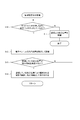
- FIG. 9 shows processing performed by the control unit 18.
- the control unit 18 first performs a process (area designation receiving process) for receiving designation of an area (first designated area) by the user (step S1).
- This process is a process of detecting that the user has performed a predetermined operation, and various kinds of specific contents of the predetermined operation are conceivable.
- 11 to 13 each show an example of specific contents of the predetermined operation, and will be described below with reference to FIGS. 11 to 13 in order. All of the operations shown in FIGS. 11 to 13 may be incorporated into the control unit 18 (that is, a plurality of area designation methods may exist), or only a part may be incorporated.
- FIG. 11 shows an example in which an operation of drawing a rectangular area with the electronic pen 4 while pressing the side switch 5 is an operation for designating a designated area.
- the control unit 18 first detects whether the user is touching the electronic pen 4 on the panel surface while pressing the side switch 5 by referring to the calculated value C2 and the pen information supplied from the position calculating unit 17. (Step S10).
- the control unit 18 is configured to be able to store the position indicated by the electronic pen 4 in a storage device (not shown), and when the determination result in step S10 is negative, discard the instruction position stored so far (step S10). S11), the process is terminated.
- step S10 determines whether or not they constitute a rectangular area.
- step S13 a series of designated positions stored so far is accepted as the designated area.
- FIG. 12 shows an example in which an operation of drawing a rectangular area with the finger 6 is an operation for designating a designated area.
- the control unit 18 detects whether the user touches the panel surface with the finger 6 by referring to the calculated value C1 supplied from the position calculating unit 17 (step S20).
- the control unit 18 is configured to be able to store the position indicated by the finger 6 in a storage device (not shown), and when the determination result in step S20 is negative, the previously stored instruction position is discarded (step S21). ), The process is terminated.
- step S20 determines whether or not they constitute a rectangular area.
- step S23 a series of designated positions stored so far is referred to and it is determined whether or not they constitute a rectangular area.
- step S24 a rectangular area constituted by a series of designated positions stored so far is accepted as a designated area (step S24), and the process proceeds to step S2 in FIG.
- FIG. 13 shows an example in which an operation of drawing a line segment with the electronic pen 4 while pressing the side switch 5 is an operation for designating a designated area.
- the control unit 18 first detects whether the user is touching the electronic pen 4 on the panel surface while pressing the side switch 5 by referring to the calculated value C2 and the pen information supplied from the position calculating unit 17. (Step S30).
- the control unit 18 is configured to be able to store the indicated position by the electronic pen 4 in a storage device (not shown), and when the determination result in step S30 is negative, discard the indicated position stored so far (step S30). S31), the process is terminated.
- step S30 determines whether or not the determination result of step S30 is affirmative.
- the control unit 18 acquires the position indicated by the electronic pen 4 at that time from the calculated value C2, and stores it in a storage device (not shown) (step S32).
- the control unit 18 detects whether or not the side switch 5 is turned off (step S33).
- step S34 determines whether or not the electronic pen 4 has been separated from the touch panel 2 (step S34).
- the control part 18 returns a process to step S30.
- step S33 if it is detected in step S33 that the side switch 5 has been turned off, or if it is determined in step S34 that the electronic pen 4 has moved away from the touch panel 2, the control unit 18 stores a series of stored indication positions. Among them, a rectangular region having a line segment connecting the one corresponding to the start point and the one corresponding to the end point as a diagonal is generated and accepted as the designated region (step S35). Then, the process proceeds to step S2 in FIG.
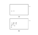
- FIG. 14A shows a state in which the touch of the electronic pen 4 is detected in step 30 of FIG.
- the touched position P1 is the starting point in step S35.
- FIG. 14B shows a state in which the side switch 5 is detected to be off in FIG. 33 or a state in which the detachment of the electronic pen 4 is detected in FIG.
- the pointing position P2 of the electronic pen 4 when these detections are made becomes the end point in step S35.
- the control unit 18 sets a line segment L1 connecting the position P1 and the position P2, and accepts a rectangle having the line segment L1 as a diagonal line as the designated region R3.
- the control unit 18 that has received the area designation in step S1 displays display data (first display data) corresponding to the designated area (steps S2 and S3).
- the shading shown in FIGS. 6 and 8 is an example of this display data.
- the specific content of the display data is not limited to the above-described shading, and for example, a straight line image or a broken line image indicating the edge of the designated area may be displayed as the display data.
- the control unit 18 performs a pop-up display for inquiring the user about the restriction target area and the restriction target input tool (step S4).
- FIG. 10 shows a specific example of this pop-up display.
- the pop-up display in this example is an option button for allowing the user to select either “in the designated area” or “outside the designated area” as the restriction target area, and “electronic pen” or “finger” as the restriction target input tool.
- the button includes an option button for causing the user to select any one of “”, “execute” button, and “cancel” button.
- step S4 is omitted.
- Step S5 when the “Cancel” button is pressed on the pop-up screen (“Cancel” determination in Step S5), the control unit 18 ends the process. In this case, the input is not restricted by the indicator.
- the control unit 18 determines whether the selected input tool is “electronic pen” or “finger” ( Step S6). As a result, when the selected input tool is “electronic pen”, the control unit 18 thereafter performs signal processing ignoring the calculated value C2 indicating the position in the restriction target region (step S7). As a result, the user recognizes that the electronic pen 4 can no longer write into the restriction target area.
- control unit 18 thereafter performs signal processing ignoring the calculated value C1 indicating the position in the restriction target region (step S8). As a result, the user recognizes that writing with the finger 6 into the restriction target area is no longer possible.
- the touch-type input system and the indicator detection apparatus 1 according to the present embodiment, only a partial area within the panel surface (that is, “inside” or “outside” of the specified area) It becomes possible to restrict input by the indicator (electronic pen 4 or finger 6). It is also possible to select an indicator that restricts input.
- the control unit 18 particularly touches after the signal processing that is different between the calculated value indicating the position corresponding to the designated area and the calculated value indicating the position corresponding to the outside of the specified area.
- the pointer detection apparatus 1 may be provided with a mechanism for returning the signal processing of the control unit 18 to the normal state.
- a button image is displayed in the display area 14a, and the signal processing of the control unit 18 is performed in a normal state when the button image is touched by the finger 6 or the electronic pen 4. It is good also as returning to.
- the designated area is received in response to the user performing a predetermined operation while pressing the side switch 5 of the electronic pen 4, but instead of the side switch 5,
- Other means such as the button 3 (see FIG. 1) of the pointer detection apparatus 1 may be used.
- the operation for designating the area is performed by touching with, for example, four fingers and sliding in the x direction (this In this case, for example, a straight line extending in the y direction including one extreme end position in the x direction among the touched coordinates, and extending in the y direction including the other extreme end position in the x direction among the touched coordinates.
- Various types can be used, such as an area surrounded by a designated area). In short, any operation that can designate a region can be adopted as an operation for designating a region.
- a predetermined pop-up display (second display data) is made by an operating system or an application such as a screen property setting screen in Windows (registered trademark)
- an area in the pop-up display is designated as a specified area (second display). (Designated area) may be accepted.
- the user can input to the input area in the pop-up screen by an input method suitable for the contents of the screen displayed in the pop-up.
- an electrostatic type sensor is used as the sensor 12 and an EMR type sensor is used as the sensor 13, but other types of sensors can also be used.
- a pressure-sensitive type may be used as the sensor 12.
- an ES system (a system in which a power supply unit such as a battery is provided in the electronic pen itself and power is not transmitted from the sensor) may be used.
- the indicator that is the detection target of the sensor 12 is not detected by the sensor 13
- the indicator that is the detection target of the sensor 13 is the sensor 12. It is preferable to configure the sensors 12 and 13 so that they are not detected.
- the present invention can also be applied to the case where only one sensor is used. This is effective not only when inputting into the signature field described above, but also when, for example, mouse input is possible or when displaying a moving image.
- mouse input is possible or when displaying a moving image.
Abstract
Description
2 タッチパネル
3 ボタン
4 電子ペン
5 サイドスイッチ
6 指
11 カバー
12,13 センサー
12A センサー12の第1の具体例
12B センサー12の第2の具体例
12C センサー12の第3の具体例
12D センサー12の第4の具体例
14 表示装置
14a 表示装置14の表示領域
15 アナログスイッチ
16 電流電圧変換部
17 位置算出部
18,37 制御部
20Aa,20Ab センサー12Aの電極
20Ba~20Bd センサー12Bの電極
20Ca~20Cd センサー12Cの電極
20Da,20Db センサー12Dの電極
21Aa,21Ab センサー12Aの端子
21Ba~21Bd センサー12Bの端子
21Ca~21Cd センサー12Cの端子
21Da,21Db センサー12Dの端子
30 選択回路
31 スイッチ回路
32 アンプ
33 検波回路
34 ローパスフィルタ
35 サンプルホールド回路
36 アナログデジタル変換回路
38 発振器
39 電流ドライバ
A1 描画領域
A2 署名欄
C1 指6による指示位置を示す算出値
C2 電子ペン4による指示位置を示す算出値
D1 センサー12の検出領域
D1a,D1b センサー12Dの検出領域
D2 センサー13の検出領域
L1 位置P1と位置P2を結ぶ線分
LC,X1~X40,Y1~Y40 ループコイル
O1 センサー12の出力信号
O2 センサー13の出力信号
P1,P2 電子ペン4の指示位置
R1~R3 指定領域 DESCRIPTION OF SYMBOLS 1 Indicator detection apparatus 2 Touch panel 3 Button 4 Electronic pen 5 Side switch 6 Finger 11 Cover 12, 13 Sensor 12A First specific example 12B of sensor 12 Second specific example 12 of sensor 12 Third specific example of sensor 12 12D Fourth Example 14 of Sensor 12 Display Device 14a Display Area 15 of Display Device 14 Analog Switch 16 Current Voltage Converter 17 Position Calculation Units 18, 37 Control Units 20Aa, 20Ab Electrodes 20Ba-20Bd of Sensor 12A Electrodes of Sensor 12B 20Ca to 20Cd Electrode 20Da and 20Db of sensor 12C Electrode 21Aa and 21Ab of sensor 12D Terminal 21Ba to 21Bd of sensor 12A Terminal 21Ca of sensor 12B 21Cd Sensor 12C terminal 21Da, 21Db Sensor 12D terminal 30 Selection circuit 31 Switch circuit 32 Amplifier 33 Detection circuit 34 Low-pass filter 35 Sample hold circuit 36 Analog-digital conversion circuit 38 Oscillator 39 Current driver A1 Drawing area A2 Signature field C1 By finger 6 Calculated value C2 indicating the indicated position Calculated value D1 indicating the indicated position by the electronic pen 4 Detection areas D1a and D1b of the sensor 12 Detection area D2 of the sensor 12D Detection area L1 of the sensor 13 Line segments LC and X connecting the position P1 and the position P2 indication position of 1 ~ X 40, Y 1 ~ Y 40 outputs signals P1, P2 electronic pen fourth output signal O2 sensor 13 of the loop coil O1 sensor 12 1 ~ R3 specified area
Claims (13)
- 指示体を検出するための検出領域を有し、該検出領域における前記指示体による指示位置に応じた出力信号を出力するセンサーと、
前記センサーに電気的に接続され、前記出力信号に基づいて前記指示体による指示位置を示す算出値を算出する位置算出部と、
前記位置算出部に電気的に接続され、該位置算出部により算出された前記算出値に基づいて、前記指示体による指示位置に応じた信号処理を行う制御部とを備え、
前記制御部は、前記位置算出部により算出される複数の前記算出値により前記指示体が前記検出領域内の第1の指定領域を指定したことが示される場合に、前記第1の指定領域内に対応する位置を示す前記算出値と、前記第1の指定領域外に対応する位置を示す前記算出値とで異なる信号処理を行う
ことを特徴とする指示体検出装置。 A sensor that has a detection area for detecting an indicator, and that outputs an output signal corresponding to an indication position by the indicator in the detection area;
A position calculator that is electrically connected to the sensor and calculates a calculated value indicating a position indicated by the indicator based on the output signal;
A control unit that is electrically connected to the position calculation unit and that performs signal processing according to the position indicated by the indicator based on the calculated value calculated by the position calculation unit;
In the first designated region, the control unit indicates that the indicator has designated the first designated region in the detection region by the plurality of calculated values calculated by the position calculating unit. The pointer detection apparatus, wherein different signal processing is performed on the calculated value indicating a position corresponding to the position and the calculated value indicating a position corresponding to outside the first designated area. - 前記検出領域に対応する表示領域を有する表示装置をさらに備え、
前記制御部は、前記表示領域に前記第1の指定領域に対応する第1の表示データを表示するよう構成される
ことを特徴とする請求項1に記載の指示体検出装置。 A display device having a display area corresponding to the detection area;
The pointer detection apparatus according to claim 1, wherein the control unit is configured to display first display data corresponding to the first designated area in the display area. - 前記制御部は、前記位置算出部により算出される複数の前記算出値により前記指示体が前記検出領域内の第1の指定領域を指定したことが示される場合に、前記第1の指定領域外に対応する位置を示す前記算出値に基づく前記信号処理を行わないよう構成される
ことを特徴とする請求項1又は2に記載の指示体検出装置。 The control unit, when the plurality of calculated values calculated by the position calculation unit indicate that the indicator has designated a first designated area in the detection area, The pointer detection apparatus according to claim 1, wherein the signal processing based on the calculated value indicating a position corresponding to is not performed. - 前記制御部は、前記位置算出部により算出される複数の前記算出値により前記指示体が前記検出領域内の第1の指定領域を指定したことが示される場合に、前記第1の指定領域内に対応する位置を示す前記算出値に基づく前記信号処理を行わないよう構成される
ことを特徴とする請求項1又は2に記載の指示体検出装置。 In the first designated region, the control unit indicates that the indicator has designated the first designated region in the detection region by the plurality of calculated values calculated by the position calculating unit. The pointer detection apparatus according to claim 1, wherein the signal processing based on the calculated value indicating a position corresponding to is not performed. - 前記制御部は、前記表示領域に第2の表示データを表示するよう構成され、
前記制御部は、前記表示領域に前記第2の表示データを表示する場合に、前記表示領域内の該第2の表示データが表示されている領域に対応する前記検出領域内の領域を第2の指定領域として指定し、その後、前記第2の指定領域内に対応する位置を示す前記算出値と、前記第2の指定領域外に対応する位置を示す前記算出値とで異なる信号処理を行う
ことを特徴とする請求項2に記載の指示体検出装置。 The control unit is configured to display second display data in the display area,
When the control unit displays the second display data in the display area, the control unit sets a second area in the detection area corresponding to an area in the display area where the second display data is displayed. Then, different signal processing is performed between the calculated value indicating the position corresponding to the second specified area and the calculated value indicating the position corresponding to the outside of the second specified area. The pointer detection apparatus according to claim 2. - 第1の指示体を検出するための第1の検出領域を有し、該第1の検出領域における前記第1の指示体による指示位置に応じた第1の出力信号を出力する第1のセンサーと、
第2の指示体を検出するための第2の検出領域を有し、該第2の検出領域における前記第2の指示体による指示位置に応じた第2の出力信号を出力する第2のセンサーと、
前記第1及び第2のセンサーのそれぞれに電気的に接続され、前記第1の出力信号に基づいて前記第1の指示体による指示位置を示す第1の算出値を算出するとともに、前記第2の出力信号に基づいて前記第2の指示体による指示位置を示す第2の算出値を算出するよう構成された位置算出部と、
前記位置算出部に電気的に接続され、該位置算出部により算出された前記第1及び第2の算出値に基づいて、前記第1及び第2の指示体のそれぞれによる指示位置に応じた信号処理を行う制御部とを備え、
前記制御部は、前記位置算出部により算出される複数の前記第1の算出値により前記第1の指示体が前記第1の検出領域内の第1の指定領域を指定したことが示される場合に、前記第1の指定領域内に対応する位置を示す前記第1の算出値と、前記第1の指定領域外に対応する位置を示す前記第1の算出値とで異なる信号処理を行うか、又は、前記第1の指定領域内に対応する位置を示す前記第2の算出値と、前記第1の指定領域外に対応する位置を示す前記第2の算出値とで異なる信号処理を行う
ことを特徴とする指示体検出装置。 A first sensor that has a first detection area for detecting a first indicator and outputs a first output signal corresponding to a position indicated by the first indicator in the first detection area. When,
A second sensor having a second detection area for detecting the second indicator, and outputting a second output signal corresponding to an indication position by the second indicator in the second detection area When,
A first calculated value that is electrically connected to each of the first and second sensors and that indicates an indication position by the first indicator based on the first output signal is calculated, and the second A position calculator configured to calculate a second calculated value indicating a position indicated by the second indicator based on the output signal of
A signal that is electrically connected to the position calculation unit and that corresponds to the position indicated by each of the first and second indicators based on the first and second calculated values calculated by the position calculation unit. A control unit that performs processing,
In the case where the control unit indicates that the first indicator has designated a first designated region in the first detection region by a plurality of the first calculated values calculated by the position calculating unit. Whether the first calculated value indicating the position corresponding to the first designated area and the first calculated value indicating the position corresponding to the outside of the first designated area are subjected to different signal processing. Alternatively, different signal processing is performed between the second calculated value indicating a position corresponding to the first designated area and the second calculated value indicating a position corresponding to the outside of the first designated area. An indicator detection apparatus characterized by that. - 前記第1及び第2のセンサーは、前記第1及び第2の検出領域が重畳するよう重ねて配置される
ことを特徴とする請求項6に記載の指示体検出装置。 The pointer detection apparatus according to claim 6, wherein the first sensor and the second sensor are arranged so as to overlap the first detection area and the second detection area. - 前記制御部は、前記位置算出部により算出される複数の前記第1の算出値により前記第1の指示体が前記第1の検出領域内の第1の指定領域を指定したことが示される場合に、前記第1の指定領域内に対応する位置を示す前記第1の算出値と、前記第1の指定領域外に対応する位置を示す前記第1の算出値とで異なる信号処理を行い、かつ、前記第1の指定領域内に対応する位置を示す前記第2の算出値と、前記第1の指定領域外に対応する位置を示す前記第2の算出値とで異なる信号処理を行う
ことを特徴とする請求項6又は7に記載の指示体検出装置。 In the case where the control unit indicates that the first indicator has designated a first designated region in the first detection region by a plurality of the first calculated values calculated by the position calculating unit. In addition, different signal processing is performed between the first calculated value indicating a position corresponding to the first designated area and the first calculated value indicating a position corresponding to the outside of the first designated area, In addition, different signal processing is performed between the second calculated value indicating a position corresponding to the first designated area and the second calculated value indicating a position corresponding to the outside of the first designated area. The pointer detection apparatus according to claim 6 or 7, characterized by the above. - 前記第1のセンサーは静電容量方式により前記第1の出力信号を生成するよう構成され、
前記第2のセンサーは電磁誘導方式により前記第2の出力信号を生成するよう構成される
ことを特徴とする請求項6乃至8のいずれか一項に記載の指示体検出装置。 The first sensor is configured to generate the first output signal in a capacitive manner;
The pointer detection apparatus according to claim 6, wherein the second sensor is configured to generate the second output signal by an electromagnetic induction method. - 前記第1のセンサーは電磁誘導方式により前記第1の出力信号を生成するよう構成され、
前記第2のセンサーは静電容量方式により前記第2の出力信号を生成するよう構成される
ことを特徴とする請求項6乃至8のいずれか一項に記載の指示体検出装置。 The first sensor is configured to generate the first output signal by electromagnetic induction;
The pointer detection apparatus according to claim 6, wherein the second sensor is configured to generate the second output signal by a capacitance method. - 指示体を検出するための検出領域を有し、該検出領域における前記指示体による指示位置に応じた出力信号を出力するセンサーと、
前記センサーに電気的に接続され、前記出力信号に基づいて前記指示体による指示位置を示す算出値を算出する位置算出部と、
前記位置算出部に電気的に接続され、該位置算出部により算出された前記算出値に基づいて、前記指示体による指示位置に応じた信号処理を行う制御部とを備え、
前記制御部は、前記指示体により前記検出領域内の第1の指定領域が指定された場合に、前記指示体による指示位置が前記第1の指定領域の内にある場合と外にある場合とで異なる信号処理を行う
ことを特徴とする指示体検出装置。 A sensor that has a detection area for detecting an indicator, and that outputs an output signal corresponding to an indication position by the indicator in the detection area;
A position calculator that is electrically connected to the sensor and calculates a calculated value indicating a position indicated by the indicator based on the output signal;
A control unit that is electrically connected to the position calculation unit and that performs signal processing according to the position indicated by the indicator based on the calculated value calculated by the position calculation unit;
When the first designated area in the detection area is designated by the indicator, the control unit includes a case where the designated position by the indicator is within the first designated area and a case where the designated position is outside the first designated area. An indicator detection apparatus characterized by performing different signal processing in - 第1の指示体を検出するための第1の検出領域を有する第1のセンサー及び第2の指示体を検出するための第2の検出領域を有する第2のセンサーを備え、前記第1及び第2の指示体のそれぞれによる指示位置に応じた信号処理を行う指示体検出装置の信号処理方法であって、
前記第1の検出領域における前記第1の指示体による指示位置に応じた第1の出力信号を得るステップと、
前記第2の検出領域における前記第2の指示体による指示位置に応じた第2の出力信号を得るステップと、
前記第1の出力信号に基づいて第1の算出値を得るステップと、
前記第2の出力信号に基づいて第2の算出値を得るステップと、
前記第1の算出値により前記第1の指示体が前記第1の検出領域内の第1の指定領域を指定しているか否かを判定するステップと、
前記第1の指定領域内に対応する位置を示す前記第1の算出値と、前記第1の指定領域外に対応する位置を示す前記第1の算出値とで異なる信号処理を行うか、又は、前記第1の指定領域内に対応する位置を示す前記第2の算出値と、前記第1の指定領域外に対応する位置を示す前記第2の算出値とで異なる信号処理を行うステップと、
を備えることを特徴とする指示体検出装置の信号処理方法。 A first sensor having a first detection region for detecting a first indicator and a second sensor having a second detection region for detecting a second indicator; A signal processing method of a pointer detection apparatus that performs signal processing according to the position indicated by each of the second pointers,
Obtaining a first output signal corresponding to a position indicated by the first indicator in the first detection region;
Obtaining a second output signal corresponding to a position indicated by the second indicator in the second detection region;
Obtaining a first calculated value based on the first output signal;
Obtaining a second calculated value based on the second output signal;
Determining whether or not the first indicator designates a first designated area in the first detection area by the first calculated value;
Performing different signal processing between the first calculated value indicating a position corresponding to the first designated area and the first calculated value indicating a position corresponding to the outside of the first designated area, or Performing different signal processing between the second calculated value indicating a position corresponding to the first designated area and the second calculated value indicating a position corresponding to the outside of the first designated area; ,
A signal processing method for a pointer detection apparatus, comprising: - 指示体を検出するための検出領域を有するセンサーを備えた指示体検出装置の信号処理方法であって、
前記指示体により指示された位置に応じた出力信号を得るステップと、
前記出力信号に基づいて前記指示位置に対応する算出値を得るステップと、
前記算出値に基づいて前記指示体が前記検出領域内の第1の指定領域を指定しているか否かを判定するステップと、
前記指示体が前記第1の指定領域を指定したと判定した場合に、前記第1の指定領域内に対応する位置を示す算出値と、前記第1の指定領域外に対応する位置を示す前記算出値とで異なる信号処理を行うステップと、
を備えることを特徴とする指示体検出装置の信号処理方法。 A signal processing method of a pointer detection apparatus including a sensor having a detection region for detecting a pointer,
Obtaining an output signal corresponding to the position indicated by the indicator;
Obtaining a calculated value corresponding to the indicated position based on the output signal;
Determining whether the indicator designates a first designated area in the detection area based on the calculated value;
When it is determined that the indicator has designated the first designated area, the calculated value indicating the position corresponding to the first designated area and the position corresponding to the outside of the first designated area are indicated. Performing different signal processing on the calculated value;
A signal processing method for a pointer detection apparatus, comprising:
Priority Applications (4)
| Application Number | Priority Date | Filing Date | Title |
|---|---|---|---|
| JP2016523357A JPWO2015182222A1 (en) | 2014-05-27 | 2015-03-18 | Indicator detection apparatus and signal processing method thereof |
| EP15799355.1A EP3151094B1 (en) | 2014-05-27 | 2015-03-18 | Indicator detection device and signal processing method thereof |
| US15/360,731 US10152184B2 (en) | 2014-05-27 | 2016-11-23 | Indicator detecting device and signal processing method thereof |
| US16/213,782 US10579198B2 (en) | 2014-05-27 | 2018-12-07 | Indicator detecting device and signal processing method thereof |
Applications Claiming Priority (2)
| Application Number | Priority Date | Filing Date | Title |
|---|---|---|---|
| JP2014-109456 | 2014-05-27 | ||
| JP2014109456 | 2014-05-27 |
Related Child Applications (1)
| Application Number | Title | Priority Date | Filing Date |
|---|---|---|---|
| US15/360,731 Continuation US10152184B2 (en) | 2014-05-27 | 2016-11-23 | Indicator detecting device and signal processing method thereof |
Publications (1)
| Publication Number | Publication Date |
|---|---|
| WO2015182222A1 true WO2015182222A1 (en) | 2015-12-03 |
Family
ID=54698564
Family Applications (1)
| Application Number | Title | Priority Date | Filing Date |
|---|---|---|---|
| PCT/JP2015/057988 WO2015182222A1 (en) | 2014-05-27 | 2015-03-18 | Indicator detection device and signal processing method thereof |
Country Status (4)
| Country | Link |
|---|---|
| US (2) | US10152184B2 (en) |
| EP (1) | EP3151094B1 (en) |
| JP (2) | JPWO2015182222A1 (en) |
| WO (1) | WO2015182222A1 (en) |
Cited By (3)
| Publication number | Priority date | Publication date | Assignee | Title |
|---|---|---|---|---|
| JP2018043652A (en) * | 2016-09-15 | 2018-03-22 | 東日本旅客鉄道株式会社 | Crew operation support system |
| WO2020154899A1 (en) * | 2019-01-29 | 2020-08-06 | 深圳市汇顶科技股份有限公司 | Pressure calculation method and apparatus using same, electronic device, and touch system |
| JP7473831B1 (en) | 2022-12-01 | 2024-04-24 | 富士通クライアントコンピューティング株式会社 | Display device and program |
Families Citing this family (6)
| Publication number | Priority date | Publication date | Assignee | Title |
|---|---|---|---|---|
| US10719132B2 (en) * | 2014-06-19 | 2020-07-21 | Samsung Electronics Co., Ltd. | Device and method of controlling device |
| JP6889064B2 (en) * | 2017-08-09 | 2021-06-18 | 株式会社ジャパンディスプレイ | Display device |
| KR102411283B1 (en) * | 2017-08-23 | 2022-06-21 | 삼성전자주식회사 | Method for determining input detection region corresponding to user interface and electronic device thereof |
| WO2019143335A1 (en) * | 2018-01-18 | 2019-07-25 | Hewlett-Packard Development Company, L.P. | Touchscreen devices to transmit input selectively |
| WO2021070313A1 (en) * | 2019-10-10 | 2021-04-15 | 株式会社ワコム | Touch detection method and touch detection device |
| CN112260661A (en) * | 2020-10-21 | 2021-01-22 | 深圳市绘王动漫科技有限公司 | Signal processing circuit and position detection device |
Citations (3)
| Publication number | Priority date | Publication date | Assignee | Title |
|---|---|---|---|---|
| JPH04127315A (en) * | 1990-09-19 | 1992-04-28 | Fujitsu Ltd | Personal computer |
| JP2013171544A (en) * | 2012-02-23 | 2013-09-02 | Wacom Co Ltd | Handwritten information input device and portable electronic equipment having handwritten information input device |
| JP2013196283A (en) * | 2012-03-19 | 2013-09-30 | Sharp Corp | Electronic equipment, method for controlling electronic equipment and program for controlling electronic equipment |
Family Cites Families (12)
| Publication number | Priority date | Publication date | Assignee | Title |
|---|---|---|---|---|
| US20030048259A1 (en) * | 1998-10-01 | 2003-03-13 | Mark Steven Rowe | Apparatus and method for achieving absolute and relative positioning of a graphics cursor |
| DE602007007765D1 (en) * | 2007-08-21 | 2010-08-26 | Wacom Co Ltd | Information processing apparatus, operation input method and computer program |
| JP2009265759A (en) * | 2008-04-22 | 2009-11-12 | Wacom Co Ltd | Position detection device and component for position detection |
| JP4857385B2 (en) * | 2010-01-12 | 2012-01-18 | パナソニック株式会社 | Electronic pen system |
| JP2012088805A (en) | 2010-10-15 | 2012-05-10 | Sharp Corp | Information processor and information processor control method |
| JP2012133704A (en) * | 2010-12-24 | 2012-07-12 | Wacom Co Ltd | Input device |
| US20130338963A1 (en) * | 2011-03-01 | 2013-12-19 | Nec Corporation | Input mechanism, input device and input mechanism control method |
| JP5790932B2 (en) * | 2011-07-29 | 2015-10-07 | 東芝ライテック株式会社 | lighting equipment |
| JP5848589B2 (en) * | 2011-12-02 | 2016-01-27 | 株式会社ワコム | Position detection apparatus and position detection method |
| JP2013164710A (en) | 2012-02-10 | 2013-08-22 | Nec Casio Mobile Communications Ltd | Electronic apparatus, its control method, and control program |
| US20130300672A1 (en) * | 2012-05-11 | 2013-11-14 | Research In Motion Limited | Touch screen palm input rejection |
| JP6127401B2 (en) | 2012-07-24 | 2017-05-17 | カシオ計算機株式会社 | Information processing apparatus, program, and information processing method |
-
2015
- 2015-03-18 EP EP15799355.1A patent/EP3151094B1/en active Active
- 2015-03-18 WO PCT/JP2015/057988 patent/WO2015182222A1/en active Application Filing
- 2015-03-18 JP JP2016523357A patent/JPWO2015182222A1/en active Pending
-
2016
- 2016-11-23 US US15/360,731 patent/US10152184B2/en active Active
-
2018
- 2018-12-07 US US16/213,782 patent/US10579198B2/en active Active
-
2020
- 2020-02-13 JP JP2020022052A patent/JP6862072B2/en active Active
Patent Citations (3)
| Publication number | Priority date | Publication date | Assignee | Title |
|---|---|---|---|---|
| JPH04127315A (en) * | 1990-09-19 | 1992-04-28 | Fujitsu Ltd | Personal computer |
| JP2013171544A (en) * | 2012-02-23 | 2013-09-02 | Wacom Co Ltd | Handwritten information input device and portable electronic equipment having handwritten information input device |
| JP2013196283A (en) * | 2012-03-19 | 2013-09-30 | Sharp Corp | Electronic equipment, method for controlling electronic equipment and program for controlling electronic equipment |
Cited By (4)
| Publication number | Priority date | Publication date | Assignee | Title |
|---|---|---|---|---|
| JP2018043652A (en) * | 2016-09-15 | 2018-03-22 | 東日本旅客鉄道株式会社 | Crew operation support system |
| WO2020154899A1 (en) * | 2019-01-29 | 2020-08-06 | 深圳市汇顶科技股份有限公司 | Pressure calculation method and apparatus using same, electronic device, and touch system |
| US11301078B2 (en) | 2019-01-29 | 2022-04-12 | Shenzhen GOODIX Technology Co., Ltd. | Method for pressure calculation and apparatus thereof, electronic device and touch system |
| JP7473831B1 (en) | 2022-12-01 | 2024-04-24 | 富士通クライアントコンピューティング株式会社 | Display device and program |
Also Published As
| Publication number | Publication date |
|---|---|
| EP3151094A1 (en) | 2017-04-05 |
| US20190107904A1 (en) | 2019-04-11 |
| US10152184B2 (en) | 2018-12-11 |
| JP6862072B2 (en) | 2021-04-21 |
| JP2020074245A (en) | 2020-05-14 |
| JPWO2015182222A1 (en) | 2017-06-01 |
| EP3151094B1 (en) | 2019-04-24 |
| US10579198B2 (en) | 2020-03-03 |
| US20170075457A1 (en) | 2017-03-16 |
| EP3151094A4 (en) | 2018-01-24 |
Similar Documents
| Publication | Publication Date | Title |
|---|---|---|
| JP6862072B2 (en) | Indicator detector and its signal processing method | |
| JP6544775B2 (en) | Position indicator, position detection device, input control method for position detection device, and input device | |
| US10268303B2 (en) | Touch and hover sensing | |
| US20140043265A1 (en) | System and method for detecting and interpreting on and off-screen gestures | |
| EP3035168B1 (en) | Pen input device, method for correcting input coordinate thereof and electronic device for supporting the same | |
| JP6249486B2 (en) | Drawing device | |
| US20100053093A1 (en) | Multi-point touch-sensitive system | |
| JP5640486B2 (en) | Information display device | |
| US20140247238A1 (en) | System and method for dual mode stylus detection | |
| KR20120004978A (en) | Detecting touch on a curved surface | |
| US11221688B2 (en) | Input apparatus with relation between pen and finger touches | |
| JP7189291B2 (en) | Position detection sensor and position detection device | |
| US11460933B2 (en) | Shield electrode for input device | |
| JP2007157107A (en) | Information processing apparatus, position detecting apparatus, and operation detecting sensing component | |
| WO2015159774A1 (en) | Input device and method for controlling input device | |
| JP2016012313A (en) | Operating device | |
| JP2015032010A (en) | Digitizer pen | |
| KR102131776B1 (en) | Input device and electronic device including the same | |
| WO2021002123A1 (en) | Terminal device and location detection sensor | |
| US20190310735A1 (en) | Method for correcting touch position of stylus | |
| JP2018081455A (en) | Instructing device, and manufacturing method |
Legal Events
| Date | Code | Title | Description |
|---|---|---|---|
| 121 | Ep: the epo has been informed by wipo that ep was designated in this application |
Ref document number: 15799355 Country of ref document: EP Kind code of ref document: A1 |
|
| ENP | Entry into the national phase |
Ref document number: 2016523357 Country of ref document: JP Kind code of ref document: A |
|
| NENP | Non-entry into the national phase |
Ref country code: DE |
|
| REEP | Request for entry into the european phase |
Ref document number: 2015799355 Country of ref document: EP |
|
| WWE | Wipo information: entry into national phase |
Ref document number: 2015799355 Country of ref document: EP |