WO2015181875A1 - カード処理装置 - Google Patents
カード処理装置 Download PDFInfo
- Publication number
- WO2015181875A1 WO2015181875A1 PCT/JP2014/063857 JP2014063857W WO2015181875A1 WO 2015181875 A1 WO2015181875 A1 WO 2015181875A1 JP 2014063857 W JP2014063857 W JP 2014063857W WO 2015181875 A1 WO2015181875 A1 WO 2015181875A1
- Authority
- WO
- WIPO (PCT)
- Prior art keywords
- shutter
- card
- stopper
- processing apparatus
- card processing
- Prior art date
- Legal status (The legal status is an assumption and is not a legal conclusion. Google has not performed a legal analysis and makes no representation as to the accuracy of the status listed.)
- Ceased
Links
Images




Classifications
-
- G—PHYSICS
- G06—COMPUTING OR CALCULATING; COUNTING
- G06K—GRAPHICAL DATA READING; PRESENTATION OF DATA; RECORD CARRIERS; HANDLING RECORD CARRIERS
- G06K13/00—Conveying record carriers from one station to another, e.g. from stack to punching mechanism
- G06K13/02—Conveying record carriers from one station to another, e.g. from stack to punching mechanism the record carrier having longitudinal dimension comparable with transverse dimension, e.g. punched card
- G06K13/06—Guiding cards; Checking correct operation of card-conveying mechanisms
Definitions
- the present invention relates to a card processing apparatus and is suitably applied to a card processing apparatus having a shutter structure.
- a shutter for permitting or prohibiting insertion of a card is disposed at a card insertion slot of the card processing apparatus.
- the shutter of the card processing device also has a function of preventing the insertion of another card, foreign object or the like from the card slot while processing the card in the card processing device.
- the card processing apparatus is provided with a plurality of rollers for transporting the card.
- the conventional card processing apparatus is provided with at least three pairs of drive rollers and idler rollers.
- a second roller is disposed in the vicinity of a magnetic head for reading the magnetism of the card
- a first roller is disposed in front of the second roller
- a third roller is disposed behind the second roller.
- the distance between the first roller and the second roller and the distance between the second roller and the third roller are the entire card length (about 86 mm) in order to keep the card transport speed constant. It is set to a slightly narrower distance.
- the shutter mechanism of the card processing device is disposed in front of the first roller. Due to the structural limitations of these card processors, the total length of the card processor excluding the shutter mechanism needs to be nearly twice or more of the total length of the card.
- the card transfer form In addition, although a configuration for shortening the processing time for processing a card is generally used, there are certain limitations in the card transfer form. For example, in order to realize read processing in the card return direction, the card is transported from the back of the card processing machine in the card processing device toward the card insertion slot, and the back end of the card reaches above the magnetic head. There are certain limitations. That is, when the card is returned, there is a restriction that the card front end must not be in contact with the closed shutter and stop, or the transport speed of the card should not change rapidly.
- the card transfer form In addition, although a configuration for shortening the processing time for processing a card is generally used, there are certain limitations in the card transfer form. Specifically, in order to realize read processing in the card return direction, the card is transported from the back of the card processing machine in the card processing device toward the card insertion slot, and the back end of the card reaches above the magnetic head. There is a restriction that the front end of the card must not come in contact with the shutter that is closed or the transport speed of the card should not change rapidly.
- the present invention has been made in consideration of the above points, and is a card capable of reliably exhibiting a card processing function while miniaturizing a card processing apparatus by arranging two pairs of card conveying rollers and two shutters. It is an attempt to propose a processing device.
- two pairs of rollers for conveying a card a first shutter provided in the vicinity of a card insertion slot, and an inner side of the card processing device than the first shutter are provided. And the first shutter and the second shutter are opened by the pressing force when the card passes, and the first shutter and the second shutter are opened according to the movement of the card by the two pairs of rollers.
- a card processing apparatus is provided, characterized in that the state is transitioned from an open state to a closed state or from a closed state to an open state.
- the first shutter is opened and the second shutter is closed, and the inserted card is a valid card.
- the second shutter is opened and the card is inserted into the inside of the card processing device by the pair of rollers to execute read / write processing of the card, the first shutter is closed.
- the second shutter is opened with the first shutter closed.
- the present invention it is possible to arrange two card transport rollers and two shutters so as to reliably exhibit the function of card processing, thereby reducing the overall cost of the processing apparatus by shortening the overall length of the processing apparatus. it can.
- the card processing apparatus is a processing apparatus for a magnetic card and an IC card.
- the card processing apparatus two pairs of card conveying rollers are disposed, and two shutters are provided.
- one shutter restricts card insertion in a state in which no card is inserted (in a state without a card) and a state in which a card is inserted by another shutter (card processing In the middle), the insertion of the next card or foreign object is restricted. Further, even if the edge of the rear end of the card hits the blade inside the card processing device during the card processing, the card processing is not disturbed.
- the configuration and function of the card processing device will be described in detail by exemplifying the card processing device 2.
- FIG. 16 is a front view of a conventional card processing apparatus.
- the card 1 (card 1 a in the figure) is inserted from the card insertion slot 3.
- the inserted card 1 (card 1 b in the figure) passes above the magnetic stripe detection head 4, a signal of magnetic data of the card 1 is detected.
- the shutter 5 is opened by an actuator such as a solenoid.
- the card 1 inserted with the shutter 5 brought into the open state is nipped and conveyed by the first card conveying roller 6a.
- the shutter 5 is closed by the actuator.
- the shutter 5 is closed, insertion of the next card and insertion of foreign matter are restricted.
- the read processing of the magnetic card is generally performed in both the card insertion direction and the card return direction. Therefore, in order to realize the read processing in the card return direction, the card 1 is transported from the back of the card processor to the card insertion slot direction, and the card 1 is transferred until the back end of the card reaches over the magnetic head. There is a constraint that the front end should not come in contact with the closed shutter or the card transport speed should not change rapidly.
- the card conveying rollers are arranged in two pairs, the magnetic head is disposed between the first roller and the second roller, and the first shutter and the second shutter are disposed in front of the first roller.
- the first shutter and the second shutter each have a stopper for restricting the movement in the opening direction, each shutter can be operated independently as required.
- the stopper for the first shutter and the second shutter it is configured to move freely in the opening direction by the movement of the card in the insertion direction and the return direction.
- two card transport rollers, a magnetic head, and two shutters are effectively arranged to enable the card processing function to be exhibited while miniaturizing the card processing apparatus.
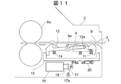
- FIG. 1 is a front view of the card processing device 2 according to the present embodiment.
- the card 1, the card processing device 2, the card insertion slot 3 and the magnetic stripe detection head 4 have the same configuration as that of FIG. 16.
- the card 1 is transported by two pairs of card transport rollers 6a and 6b.
- the axial distance L between the card conveyance rollers 6a and 6b is set to a distance slightly narrower than the total length (about 86 mm) of the card 1.
- the read / write magnetic head 7 and the IC contact 8 are disposed between the card transport rollers 6a and 6b.
- the first shutter 9 and the second shutter 12 are disposed in front of the card conveyance roller 6a.
- the magnetic stripe detection head 4 is disposed between the first shutter 9 and the second shutter 12.
- the first shutter 9 and the second shutter 12 have a first shutter stopper 10 and a second shutter stopper 13 for restricting the movement of the respective shutters in the opening direction.
- the first shutter stopper 10 and the second shutter stopper 13 can be moved independently by an actuator (not shown) such as a solenoid.
- the first shutter stopper 10 and the second shutter stopper 13 are respectively located below the first shutter 9 and the second shutter 12 and are moved up and down by an actuator.
- the first shutter stopper 10 and the second shutter stopper 13 move upward, that is, when they are in contact with the first shutter 9 and the second shutter 12, the first shutter 9 and the second shutter 12 rotate. It is fixed without.
- the first shutter stopper 10 and the second shutter stopper 13 move downward by the actuator, the first shutter 9 and the second shutter 12 can rotate to the position of the shutter stopper around their respective rotation axes.
- the first shutter 9 and the second shutter 12 respectively have inclined portions with respect to the insertion direction and the return direction of the card 1.
- the first pressing force of the card causes the first shutter stopper 10 and the second shutter stopper 13 to move downward.
- the shutter 9 and the second shutter 12 can be rotated about the rotation axis to move the shutter in the opening direction.
- the first shutter 9 rotates counterclockwise around the rotation shaft 9a, and the first shutter 9 is opened. Move in the direction.
- the second shutter 12 rotates clockwise about the rotation shaft 12a, and the second shutter moves in the opening direction.
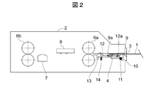
- FIG. 2 shows a state in which the card 1 is inserted from the card insertion slot 3 by the end user.
- the first shutter stopper 10 restricting the downward movement of the first shutter 9 is located below the first shutter 9.
- the first shutter stopper 10 is moved up and down below the first shutter 9 by the actuator.
- the first shutter stopper 10 is moved downward by the actuator. Therefore, when the card 1 is inserted from the card insertion slot 3, the first shutter 9 is rotated clockwise about the rotation axis 9a by the pressing force of the card 1 to enable the insertion of the card 1. .
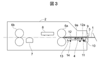
- the magnetic stripe detection head 4 When data is held in the magnetic stripe of the card 1, the magnetic stripe detection head 4 reads data of the magnetic stripe to detect a predetermined signal. When it is determined from the detected signal that the card 1 is the correct card, as shown in FIG. 3, the second shutter stopper 13 is lowered by the actuator to insert the card 1 in the direction of the card conveyance roller 6a. Allow Similar to the first shutter 9, when the card 1 is inserted from the direction of the first shutter 9, the second shutter 12 is rotated counterclockwise around the rotation axis 12 a by the pressing force of the card 1. , Allows the insertion of the card 1.
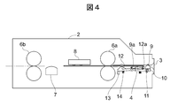
- FIG. 4 shows a state where the card 1 has reached the position of the card conveyance roller 6a and has reached the pressed position of the IC contact 8 by the card conveyance roller 6a.
- the first shutter stopper 10 is moved upward to move the first shutter 9 in the closing direction. In this manner, by restricting the movement of the first shutter 9 in the opening direction, the next card is prevented from being inserted or the foreign matter is being inserted.
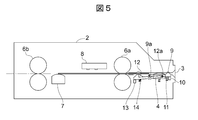
- FIG. 5 shows a state in which the front end of the card 1 reaches the read / write magnetic head 7 to start the process of reading or writing magnetic data.
- the first shutter stopper 10 keeps the first shutter 9 closed with respect to the insertion opening 3 while moving upward. As described above, the movement of the first shutter 9 in the opening direction is restricted to prevent the insertion of the next card and the foreign object.
- FIG. 6 shows a state where the rear end of the card 1 has reached the read / write magnetic head 7 and the read or write processing of magnetic data has been completed.
- the card 1 transitions from the state of FIG. 6 to the state of FIG.
- the second shutter stopper 13 is located below the second shutter 12. For this reason, when the card 1 moves in the return direction, the second shutter 12 is rotated counterclockwise around the rotation axis 12a by the pressing force of the card 1 and operates in the opening direction.
- the first shutter stopper 10 is moved downward to make the first shutter 9 rotatable in the opening direction. Then, when the card 1 is transported in the return direction by the rollers 6a and 6b, the pressing force of the card 1 causes the first shutter 9 to rotate clockwise about the rotation shaft 9a and operate in the opening direction.
- the card conveyance rollers are made into two pairs of the first roller 6a and the second roller 6b, and the first roller 6a and the second roller 6b are used. And the first shutter 9 and the second shutter 12 are disposed in front of the first roller 6a.
- the two card transfer rollers and the two shutters so as to reliably exhibit the function of card processing, it is possible to shorten the overall length of the processing apparatus and reduce the cost of the entire processing apparatus. .
- Second Embodiment The present embodiment is different from the first embodiment in that the operation of the two shutters provided in the card processing device 2 is controlled by only one solenoid. It has become. This will be described in detail below with reference to FIGS. 7 to 12.
- the operation of the first shutter 9 and the second shutter 12 of the card processing device 2 is controlled by one solenoid 16. Further, in the first embodiment, the operation of the first shutter 9 and the second shutter 12 is restricted by two shutter stoppers, but in the present embodiment, the first shutter 9 and the second shutter 12 are restricted by one shutter stopper 15. The movement of the second shutter 12 is restricted.
- a link spring 19 and a stopper return spring 20 are provided under the shutter stopper 15, and the force of the solenoid 15 is transmitted to the shutter stopper 15 via the link spring 19 and the stopper return spring 20.
- the solenoid return spring 18 of the solenoid 16 moves, the link 17 connecting the solenoid return spring 18 and the link spring 19 moves, and the shutter stopper 15 moves to the left or right according to the movement of the link spring 19 and the stopper return spring 20. Moving.
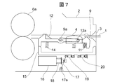
- FIG. 7 shows a state in which the card 1 is inserted from the card insertion slot 3 by the end user.
- no voltage is applied to the solenoid 16.
- the shutter stopper 15 is biased by the stopper return spring 20 in the right direction of FIG. 7, that is, in the direction of the card insertion slot 3. Since the first shutter 9 is not in contact with the projection of the shutter stopper 15, the first shutter 9 can rotate clockwise about the rotation shaft 9a. Further, since the second shutter 12 is in contact with the projection of the shutter stopper 15, the movement in the opening direction is restricted.
- the magnetic stripe detection head 4 When data is held in the magnetic stripe of the card 1, the magnetic stripe detection head 4 reads data of the magnetic stripe to detect a predetermined signal. Then, when it is determined from the detected signal that the card 1 is a correct card, the actuator 16 is operated to move the shutter stopper 15 to a position where the insertion of the card 1 is permitted.
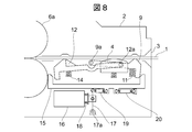
- FIG. 8 shows a state in which a voltage is applied to the solenoid 16 to permit insertion of the card 1.
- the force of the solenoid 16 is transmitted to the shutter stopper 15 via the link spring 19 to move in the left direction in FIG.
- the link spring 19 is a spring stronger than the stopper return spring 20.
- the shutter stopper 15 is urged in the left direction of FIG. 8, but stops in contact with the first shutter 9.
- the card conveyance roller 6a in the left direction of FIG. 8 in contact with the card conveyance roller 6a.
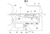
- FIG. 9 shows a state in which the card 1 is conveyed by the card conveyance roller 6 a in the depth direction of the card processing device 2, and the rear end of the card 1 exceeds the first shutter 9.
- the first shutter 9 is moved in the closing direction by the first shutter spring 11.
- the shutter stopper 15 since the shutter stopper 15 is biased in the left direction of FIG. 9 by the link spring 19, the shutter stopper 15 moves from the position of FIG. 8 to the position of FIG.
- the projection of the shutter stopper 15 contacts the first shutter 9 to restrict the movement of the first shutter 9 in the opening direction. In this manner, by restricting the movement of the first shutter 9 in the opening direction, the next card is prevented from being inserted or the foreign matter is being inserted.
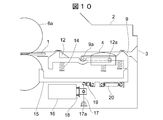
- FIG. 10 shows a state in which the card 1 is further transported in the depth direction of the card processing device 2 and the rear end of the card 1 has exceeded the second shutter 12.
- the second shutter 12 is moved in the closing direction by the second shutter spring 14.
- the shutter stopper 15 is moved in the left direction in FIG. 10 by the solenoid 16
- the movement of the second shutter 12 in the opening direction is not restricted by the projection of the shutter stopper 15. Therefore, when the rear end of the card 1 moves in the direction of the card insertion slot 3 again, the second shutter 12 is rotated clockwise about the rotation shaft 12a by the pressing force of the card 1 to open it. Run.
- FIG. 11 shows a state in which the card 1 is conveyed in the direction of the card insertion slot 3 and the front end of the card 1 has exceeded the first shutter 9. At this time, since no voltage is applied to the solenoid 16, the shutter stopper 15 is urged by the stopper return spring 20 in the right direction of FIG. The projection of the shutter stopper 15 is in contact with the second shutter 12 and stopped.
- Such a state is a state in which the end user is waiting for card removal.
- FIG. 12 shows a state where the end user has begun to remove the card 1 from the state of FIG.
- the second shutter 12 is moved in the closing direction by the second shutter spring 14. Then, the projection of the shutter stopper 15 contacts the second shutter 12 to restrict the movement of the second shutter 12 in the opening direction.
- the end user since the card 1 can not be inserted in the depth direction of the card processing device 2 again beyond the second shutter 12, the end user may accidentally push the returned card into the card processing device 2. It can be prevented.
- the present embodiment is configured to detect that a malicious user has set up a dental floss-like thin and strong thread-like card trap 21 inside the card processing apparatus 2. It is added. The details will be described below with reference to FIGS. 13 to 15.
- the configuration of the card processing device 2 of the present embodiment will be described in detail for the configuration different from the configuration of the card processing device 2 of the second embodiment, and the detailed description of the same configuration as the second embodiment. Omit.
- the hatched portion 12b of the second shutter 12 has a rotation center in the second shutter 12, and is normally biased by a leaf spring or the like so as to be disposed at the position shown in FIG. .
- FIG. 14 when the card trap 21 is set inside the card processing apparatus 2, the hatched portion 12b is pressed by the card trap 21 and is moved downward as shown in FIG. Thus, the hatched portion 12b moves separately from the normal operation of the second shutter 12, and the second shutter 12 and the hatched portion 12b shift.
- the card trap 21 is monitored by detecting the displacement between the second shutter 12 and the hatched portion 12b by monitoring the movement of the hatched portion 12b with a photo sensor or a micro switch (not shown) provided in the card processing device 2. It is possible to detect that the
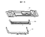
- FIG. 15 is a perspective view of the upper portion 22 of the card conveyance path of the card processing device 2 shown in FIG. 13 and the hatched portion 12b of the second shutter 12 and the second shutter 12.
- gaps of 2-3 mm width are continuously arranged in the card width direction at a pitch of about 5 mm.
- protrusions which enter the gap provided in the upper portion 22 of the card conveyance path are continuously arranged in the card width direction.
- the magnetic head 7 is disposed between the first roller 6a and the second roller 6b.
- the first shutter 9 and the second shutter 12 are disposed in the front.
Landscapes
- Physics & Mathematics (AREA)
- General Physics & Mathematics (AREA)
- Engineering & Computer Science (AREA)
- Theoretical Computer Science (AREA)
- Conveying Record Carriers (AREA)
Abstract
【課題】2対のカード搬送ローラ及び2つのシャッタを効果的に配置して、カード処理機能を確実に発揮する。 【解決手段】カード処理装置は、カードを搬送する2対のローラと、カード挿入口付近に設けられた第1のシャッタと、前記第1のシャッタよりカード処理装置の内部側に設けられた第2のシャッタと、を備え、前記第1のシャッタ及び前記第2のシャッタは、前記カードが通過する際の押圧力により開状態となり、前記2対のローラによる該カードの移動に応じて開状態から閉状態または閉状態から開状態に状態を遷移させる。
Description
本発明は、カード処理装置に関し、シャッタ構造を有するカード処理装置に適用して好適なるものである。
磁気カードやICカードなどを扱うカード処理装置において、カードの挿入を許可したり禁止したりするためのシャッタが、カード処理装置のカード挿入口部に配置されている。また、カード処理装置のシャッタは、カード処理装置内でカードを処理している間に、カード挿入口から別のカードや異物などを挿入されることを防ぐ機能も有している。
また、カード処理装置は、カードを搬送するために複数のローラを備えている。図16に示すように、従来のカード処理装置には、少なくとも3対のドライブローラとアイドラローラが備えられている。一般的に、カードの磁気を読み取る磁気ヘッド近傍に第2ローラが配置され、第2ローラの前方に第1ローラ、第2ローラの後方に第3ローラが配置される。
また、カード処理装置では、磁気カードのリード及びライトを正常に行うために、カードの搬送速度を一定に保つ必要がある。図16に示す従来のカード処理装置では、カードの搬送速度を一定に保つために、第1ローラと第2ローラの間隔及び、第2ローラと第3ローラの間隔は、カード全長(約86mm)よりも少し狭い距離に設定される。また、カード処理装置のシャッタ機構は、第1ローラの前に配置される。これらのカード処理装置の構成上の制約から、シャッタ機構を除くカード処理装置の全長はカードの全長の2倍近く又はそれ以上の長さが必要となる。
また、カードを処理するための処理時間を短縮する構成が一般的であるが、カードの搬送形態にも一定の制約がある。例えば、カード返却方向でのリード処理を実現するために、カードがカード処理装置内のカード処理機の後方からカード挿入口方向に搬送され、カードの後端が磁気ヘッドの上に達するまでにも一定の制約がある。すなわち、カードを返却する際には、カード前端が閉じているシャッタに接触して止まるか、カードの搬送速度が急激に変化することがあってはならないという制約がある。
また、ICカードを処理する場合には、ICカードがIC接点を押下した状態で、次のカード又は異物をカード挿入口から挿入されて処理中のICカードが動いて、ICカード処理が妨げられるのを防ぐ必要がある。このため、ICカードがIC接点を押下した状態で、ICカードの後端がシャッタの内側にあることが必要となる。
また、カードを処理するための処理時間を短縮する構成が一般的であるが、カードの搬送形態にも一定の制約がある。具体的には、カード返却方向でのリード処理を実現するため、カードがカード処理装置内のカード処理機の後方からカード挿入口方向に搬送され、カードの後端が磁気ヘッドの上に達するまでにカード前端が閉じているシャッタに接触して止まるか、カードの搬送速度が急激に変化することがあってはならないという制約がある。
また、ICカードを処理する場合には、ICカードがIC接点を押下した状態で、次のカード又は異物をカード挿入口から挿入されて、処理中のICカードが動き、結果として、ICカード処理が妨げられるのを防がなければならに。このために、IC接点をカード押下した状態で、ICカードの後端がシャッタの内側にあることが必要となる。
さらに、上記制約を実現しつつ、カード処理装置の構成を簡素化したり小型化するなどして、カード処理装置全体の管理を容易にすることが求められている。
本発明は以上の点を考慮してなされたもので、2対のカード搬送ローラ及び2つのシャッタを配置してカード処理装置を小型化しつつ、カード処理機能を確実に発揮することが可能なカード処理装置を提案しようとするものである。
かかる課題を解決するために本発明においては、カードを搬送する2対のローラと、カード挿入口付近に設けられた第1のシャッタと、前記第1のシャッタよりカード処理装置の内部側に設けられた第2のシャッタと、を備え、前記第1のシャッタ及び前記第2のシャッタは、前記カードが通過する際の押圧力により開状態となり、前記2対のローラによる該カードの移動に応じて開状態から閉状態または閉状態から開状態に状態を遷移させることを特徴とする、カード処理装置装置が提供される。
具体的に、状態の遷移は、前記カードが挿入される前は、前記第1シャッタを開状態、前記第2シャッタを閉状態とし、挿入された該カードが正当なカードである場合には、前記第2シャッタを開状態とし、前記カードが前記2対のローラにより前記カード処理装置の内部に挿入されて該カードのリードライト処理を実行する場合には、前記第1シャッタを閉状態とし、前記カードが前記2対のローラにより前記カード挿入口付近に移動して該カードの磁気データをリードする場合には、前記第1シャッタを閉状態のまま前記第2シャッタを開状態とする。
本発明によれば、カード処理の機能を確実に発揮するように、2つのカード搬送ローラ及び2つのシャッタを配置して、処理装置の全長を短くして処理装置全体のコストを削減することができる。
以下図面について、本発明の一実施の形態を詳述する。
(1)第1の実施の形態
(1-1)本実施の形態の概要
本実施の形態にかかるカード処理装置は、磁気カード及びICカードの処理装置である。カード処理装置には、カード搬送ローラを2対配置し、シャッタを2枚構成としている。シャッタを2枚構成としているカード処理装置は、一のシャッタでカードが挿入されていない状態(カード無しの状態)でカード挿入を規制し、他のシャッタでカードが挿入されている状態(カード処理中)の次のカード又は異物の挿入を規制している。また、カード処理中に、カード後端のエッジがカード処理装置の内側のブレードに当たっても、カード処理を妨げない構成としている。以下、カード処理装置2を例示してカード処理装置の構成及び機能を詳細に説明する。
(1)第1の実施の形態
(1-1)本実施の形態の概要
本実施の形態にかかるカード処理装置は、磁気カード及びICカードの処理装置である。カード処理装置には、カード搬送ローラを2対配置し、シャッタを2枚構成としている。シャッタを2枚構成としているカード処理装置は、一のシャッタでカードが挿入されていない状態(カード無しの状態)でカード挿入を規制し、他のシャッタでカードが挿入されている状態(カード処理中)の次のカード又は異物の挿入を規制している。また、カード処理中に、カード後端のエッジがカード処理装置の内側のブレードに当たっても、カード処理を妨げない構成としている。以下、カード処理装置2を例示してカード処理装置の構成及び機能を詳細に説明する。
(1-2)従来のカード処理装置の構成
本実施形態のカード処理装置の構成を説明する前に、図16を参照して、一般的な構成を有する従来の磁気カード及びICカード処理装置について説明する。
本実施形態のカード処理装置の構成を説明する前に、図16を参照して、一般的な構成を有する従来の磁気カード及びICカード処理装置について説明する。
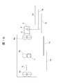
図16は、従来のカード処理装置の正面図である。図16に示すように、カード1(図中のカード1a)は、カード挿入口3から挿入される。挿入されたカード1(図中のカード1b)が磁気ストライプ検知ヘッド4の上を通過すると、カード1の磁気データの信号が検出される。そして、カード1(図中のカード1c)の前端がシャッタ5に達する前に、シャッタ5は、ソレノイドなどのアクチュエータで開状態にされる。
開状態にされたシャッタ5をから挿入されたカード1は、第1のカード搬送ローラ6aに挟持されて搬送される。カード1(図中のカード1d)の前端が、リード・ライト用磁気ヘッド7に達すると、シャッタ5は、アクチュエータで閉状態にされる。シャッタ5が閉状態となることにより、次のカードの挿入や、異物の挿入が規制される。
また、カードに対する処理時間を短縮するために、磁気カードのリード処理はカード挿入方向及び、カード返却方向の両方で実施する構成が一般的である。そこで、カード返却方向でのリード処理を実現するために、カード1が、カード処理機の後方からカード挿入口方向に搬送されて、カード後端が磁気ヘッドの上に達するまでに、カード1の前端が閉じられたシャッタに接触して止まるか、カードの搬送速度が急激に変化することがあってはならないという制約が設けられている。
また、ICカードを処理する場合には、カード1がIC接点8を押下した状態で、カード挿入口3から次のカードが挿入されたり異物が挿入されることが考えられる。この場合、処理中のICカードが別のカードや異物により動かされ、ICカード処理が妨げられてしまう。これを防ぐために、カード1がIC接点8を押下した状態で、ICカードの後端がシャッタ5の内側に位置している必要がある。
そこで、本実施の形態では、カード搬送ローラを2対にして第1ローラと第2ローラとの間に磁気ヘッドを配置し、第1ローラの前方に第1シャッタと第2シャッタを配置する構成とした。また、第1シャッタ及び第2シャッタは、それぞれその開方向の動きを規制するストッパを有しているため、必要に応じて各シャッタを独立して動作させることができる。また第1シャッタび第2シャッタに対してストッパの規制が無い場合には、カードの挿入方向及び返却方向の動きによって自在に開方向に動く構成としている。このように、2つのカード搬送ローラ、磁気ヘッド及び2つのシャッタを効果的に配置して、カード処理装置を小型化としつつ、カード処理の機能を発揮することを可能としている。
(1-3)カード処理装置の構成
図1は、本実施の形態にかかるカード処理装置2の正面図である。カード1、カード処理装置2、カード挿入口3及び磁気ストライプ検知ヘッド4は、図16の構成と同様である。
図1は、本実施の形態にかかるカード処理装置2の正面図である。カード1、カード処理装置2、カード挿入口3及び磁気ストライプ検知ヘッド4は、図16の構成と同様である。
図1に示すように、カード1は、カード搬送ローラ6a及び6bの2対のローラで搬送される。カード搬送ローラ6aと6bとの軸間距離Lは、カード1の全長(約86mm)よりも少し狭い距離に設定されている。また、リード・ライト用磁気ヘッド7及びIC接点8は、カード搬送ローラ6aと6bとの間に配置される。
カード搬送ローラ6aの前方に、第1シャッタ9及び第2シャッタ12が配置される。磁気ストライプ検知ヘッド4は、第1シャッタ9と第2シャッタ12との間に配置される。そして、第1シャッタ9及び第2シャッタ12は、各シャッタの開方向の動きを規制する第1シャッタストッパ10及び第2シャッタストッパ13を有する。
第1シャッタストッパ10及び第2シャッタストッパ13は、ソレノイドなどのアクチュエータ(図示せず)によって独立に動かすことができる。第1シャッタストッパ10及び第2シャッタストッパ13は、それぞれ、第1シャッタ9及び第2シャッタ12の下方に位置し、アクチュエータによって上下に移動する。第1シャッタストッパ10及び第2シャッタストッパ13が上部に移動する場合、すなわち、第1シャッタ9及び第2シャッタ12に接触する位置にある場合には、第1シャッタ9及び第2シャッタ12は回転せずに固定される。一方、第1シャッタストッパ10及び第2シャッタストッパ13がアクチュエータによって下部に移動すると、第1シャッタ9及び第2シャッタ12は、それぞれの回転軸を中心にシャッタストッパの位置まで回転可能となる。
第1シャッタ9及び第2シャッタ12は、それぞれカード1の挿入方向及び返却方向に対して傾斜部を有している。これにより、第1シャッタストッパ10及び第2シャッタストッパ13の規制が無い場合、すなわち、第1シャッタストッパ10及び第2シャッタストッパ13が下部に移動しているときには、カードの押圧力によって、第1シャッタ9及び第2シャッタ12が回転軸を中心に回転して、シャッタを開方向に動かすことができる。例えば、カード1がカード挿入口3から挿入されて第1シャッタ9に挿入されたりる場合に、第1シャッタ9が回転軸9aを中心に反時計回りに回転して、第1シャッタ9が開方向に動く。また、カード1が第2シャッタ12から返却される場合には、第2シャッタ12が回転軸12aを中心に時計回りに回転して、第2シャッタが開方向に動く。
(1-4)カード処理装置の動作
次に、図2~図6を参照して、カード1が、カード挿入口3からカード処置装置2の奥行方向に移動する場合のカード処理装置2の各部の動作について説明する。
次に、図2~図6を参照して、カード1が、カード挿入口3からカード処置装置2の奥行方向に移動する場合のカード処理装置2の各部の動作について説明する。
図2は、カード1がエンドユーザによってカード挿入口3から挿入された状態を示す。カード1が挿入される前は、第1シャッタ9の下方向の動きを規制している第1シャッタストッパ10は、第1シャッタ9の下方に位置している。上記したように、第1シャッタストッパ10は、アクチュエータによって第1シャッタ9の下方で上下に移動する。カード1がカード挿入口3から挿入されると、第1シャッタストッパ10はアクチュエータによって下部に移動する。したがって、カード挿入口3からカード1が挿入されると、第1シャッタ9は、カード1の押圧力によって、その回転軸9aを中心に時計回りに回転して、カード1の挿入を可能とする。
カード1の磁気ストライプにデータが保持されている場合は、磁気ストライプ検知ヘッド4が磁気ストライプのデータを読み取って、所定の信号を検出する。そして、検出した信号からカード1が正しいカードであると判定した場合には、図3に示すように、第2シャッタストッパ13をアクチュエータによって下方に下げ、カード搬送ローラ6aの方向にカード1の挿入を許可する。第1シャッタ9と同様に、カード1が第1シャッタ9の方向から挿入されると、第2シャッタ12は、カード1の押圧力によって、その回転軸12aを中心に反時回りに回転して、カード1の挿入を可能とする。
図4は、カード1がカード搬送ローラ6aの位置に到達して、カード搬送ローラ6aによってIC接点8の押下位置に達した状態を示す。このとき、第1シャッタストッパ10を上部に移動して、第1シャッタ9を閉方向に動かす。このように、第1シャッタ9の開方向への動きを規制することにより、次のカードが挿入されたり、異物が挿入されたりすることを防止する。
図5は、カード1の前端がリード・ライト用磁気ヘッド7に達して、磁気データのリード又はライト処理を開始する状態を示す。第1シャッタストッパ10は、上部に移動したまま、第1シャッタ9が挿入口3に対して閉じた状態を維持している。このように、第1シャッタ9の開方向への動きを規制して、引き続き次のカードの挿入や異物の挿入を防止している。
図6は、カード1の後端がリード・ライト用磁気ヘッド7に達して、磁気データのリード又はライト処理が終了した状態を示す。カード返却方向で磁気データのリード処理を実施する場合は、カード1が図6の状態から図5の状態に遷移する。このとき、第2シャッタストッパ13は、第2シャッタ12の下部に位置している。このため、カード1が返却方向に移動すると、第2シャッタ12は、カード1の押圧力によって、その回転軸12aを中心に反時計回りに回転して開方向に稼働する。
さらに、カード1をストッパに返却する場合は、第1シャッタストッパ10を下部に移動して、第1シャッタ9を開方向に回転可能とする。そして、カード1をローラ6a及び6bで返却方向に搬送すると、カード1の押圧力によって第1シャッタ9がその回転軸9aを中心に時計回りに回転して開方向に稼働する。
(1-5)本実施の形態の効果
上記したように、本実施の形態では、カード搬送ローラを第1ローラ6aと第2ローラ6bの2対にして、第1ローラ6aと第2ローラ6bとの間に磁気ヘッド7を配置し、第1ローラ6aの前方に第1シャッタ9及び第2シャッタ12を配置するという構成にしている。このように、カード処理の機能を確実に発揮するように、2つのカード搬送ローラ及び2つのシャッタを配置することにより、処理装置の全長を短くして処理装置全体のコストを削減することができる。
上記したように、本実施の形態では、カード搬送ローラを第1ローラ6aと第2ローラ6bの2対にして、第1ローラ6aと第2ローラ6bとの間に磁気ヘッド7を配置し、第1ローラ6aの前方に第1シャッタ9及び第2シャッタ12を配置するという構成にしている。このように、カード処理の機能を確実に発揮するように、2つのカード搬送ローラ及び2つのシャッタを配置することにより、処理装置の全長を短くして処理装置全体のコストを削減することができる。
(2)第2の実施の形態
本実施の形態は、カード処理装置2に備えられた2つのシャッタの動作を1つのソレノイドのみで制御している点で第1の実施の形態と異なる構成となっている。以下、図7~図12を参照して詳細に説明する。
本実施の形態は、カード処理装置2に備えられた2つのシャッタの動作を1つのソレノイドのみで制御している点で第1の実施の形態と異なる構成となっている。以下、図7~図12を参照して詳細に説明する。
(2-1)カード処理装置の構成
以下では、第1の実施形態と異なる2つのシャッタの構成及び動作について詳細に説明し、第1の実施の形態と同様の構成については詳細な説明を省略する。
以下では、第1の実施形態と異なる2つのシャッタの構成及び動作について詳細に説明し、第1の実施の形態と同様の構成については詳細な説明を省略する。
図7に示すように、カード処理装置2の第1シャッタ9及び第2シャッタ12の動作は、1つのソレノイド16により制御されている。また、第1の実施の形態では、2つのシャッタストッパにより第1シャッタ9及び第2シャッタ12の動作を規制していたが、本実施の形態では、1つのシャッタストッパ15により第1シャッタ9及び第2シャッタ12の動きを規制している。
図7に示すように、シャッタストッパ15の下部にはリンクバネ19及びストッパ戻しバネ20が備えられ、リンクバネ19及びストッパ戻しバネ20を介してソレノイド15の力がシャッタストッパ15に伝えられる。ソレノイド16のソレノイド戻しバネ18が移動すると、ソレノイド戻しバネ18とリンクバネ19を接続しているリンク17が移動して、リンクバネ19及びストッパ戻しバネ20の動きに応じてシャッタストッパ15が左右に移動する。
(2-2)カード処理装置の動作
次に、図7~図12を参照して、カード1が、カード挿入口3からカード処置装置2の奥行方向に移動する場合のカード処理装置2の各部の動作について説明する。
次に、図7~図12を参照して、カード1が、カード挿入口3からカード処置装置2の奥行方向に移動する場合のカード処理装置2の各部の動作について説明する。
図7は、カード1がエンドユーザによってカード挿入口3から挿入された状態を示す。カード1が挿入される前、すなわち、カード1の挿入待ちの状態の場合には、ソレノイド16に電圧を印加していない。ソレノイド16に電圧が印加されていない状態では、シャッタストッパ15は、ストッパ戻しバネ20によって図7の右方向、すなわち、カード挿入口3の方向に付勢されている。第1シャッタ9は、シャッタストッパ15の突起部と接していないため、回転軸9aを中心に時計回りに回転可能な状態である。また、第2シャッタ12は、シャッタストッパ15の突起部に接しているため開方向の動きを規制されている。
図7に示すように、カード1がカード挿入口3から挿入されると、第1シャッタ9は、カード1の押圧力によって、その回転軸9aを中心に時計回りに回転し、カード1の挿入を可能とする。
カード1の磁気ストライプにデータが保持されている場合は、磁気ストライプ検知ヘッド4が磁気ストライプのデータを読み取って、所定の信号を検出する。そして、検出した信号からカード1が正しいカードであると判定した場合には、アクチュエータ16を動作させて、シャッタストッパ15をカード1の挿入を許可する位置に移動させる。
図8は、カード1の挿入を許可するために、ソレノイド16に電圧を印加した状態を示す。シャッタストッパ15には、リンクバネ19を介してソレノイド16の力が伝えられて、図8の左方向に移動する。リンクバネ19は、ストッパ戻しバネ20よりも強いバネとしている。図8に示すように、シャッタストッパ15は、図8の左方向に付勢されているが、第1シャッタ9に接触して止まっている。この状態でさらにカード1が奥に挿入されると、カード搬送ローラ6aに接して、カード搬送ローラ6aによってさらに図8の左方向に搬送される。
図9は、カード1がカード搬送ローラ6aによってカード処理装置2の奥行方向に搬送されて、カード1の後端が第1シャッタ9を超えた状態を示す。第1シャッタ9の突起部をカード1が超えると、第1シャッタ9は、第1シャッタばね11によって閉方向に移動する。そして、シャッタストッパ15は、リンクバネ19によって図9の左方向に付勢されているため、図8の位置から図9の位置まで移動する。そして、シャッタストッパ15の突起部が第1シャッタ9に接触して、第1シャッタ9の開方向の動きを規制する。このように、第1シャッタ9の開方向への動きを規制することにより、次のカードが挿入されたり、異物が挿入されたりすることを防止する。
図10は、カード1がさらにカード処理装置2の奥行方向に搬送されて、カード1の後端が第2シャッタ12を超えた状態を示す。第2シャッタ12の突起部をカード1が超えると、第2シャッタ12は、第2シャッタばね14によって閉方向に移動する。しかし、シャッタストッパ15は、ソレノイド16によって図10の左方向に移動しているため、シャッタストッパ15の突起部によって第2シャッタ12の開方向の動きは規制されていない。したがって、再度カード1の後端がカード挿入口3の方向に移動した場合には、第2シャッタ12は、カード1の押圧力によってその回転軸12aを中心に時計回りに回転して開方向に稼働する。
図11は、カード1がカード挿入口3の方向に搬送されて、カード1の前端が第1シャッタ9を超えた状態を示す。このとき、ソレノイド16に電圧は印加されていないため、シャッタストッパ15は、ストッパ戻しバネ20によって図11の右方向に付勢されている。そして、シャッタストッパ15の突起部が第2シャッタ12に接触して止まっている。このような状態は、エンドユーザのカード抜き取り待ちの状態である。
図12は、図11の状態から、エンドユーザによってカード1が抜き取られ始めた状態を示す。カード1の後端が第2シャッタ12の突起部を通過すると、第2シャッタ12は、第2シャッタばね14によって閉方向に移動する。そして、シャッタストッパ15の突起部が第2シャッタ12に接触して、第2シャッタ12の開方向の動きを規制する。このような状態では、第2シャッタ12を超えてカード1を再度カード処理装置2の奥行方向に挿入することはできないため、返却されたカードをエンドユーザが誤ってカード処理装置2に押し込むことを防止することができる。
(2-3)本実施の形態の効果
本実施の形態では、第1の実施の形態と同様に、カード搬送ローラを2対にして、第1ローラ6aと第2ローラ6bとの間に磁気ヘッド7を配置し、第1ローラの前方に第1シャッタ9及び第2シャッタ12を配置するという構成にしている。このように、カード処理の機能を確実に発揮するように、2つのカード搬送ローラ及び2つのシャッタを配置して、処理装置の全長を短くして処理装置全体のコストを削減することができる。また、1つのソレノイドで2つのシャッタの動作を制御することができるため、部品点数を少なくして、さらに構成を簡素化することができる。
本実施の形態では、第1の実施の形態と同様に、カード搬送ローラを2対にして、第1ローラ6aと第2ローラ6bとの間に磁気ヘッド7を配置し、第1ローラの前方に第1シャッタ9及び第2シャッタ12を配置するという構成にしている。このように、カード処理の機能を確実に発揮するように、2つのカード搬送ローラ及び2つのシャッタを配置して、処理装置の全長を短くして処理装置全体のコストを削減することができる。また、1つのソレノイドで2つのシャッタの動作を制御することができるため、部品点数を少なくして、さらに構成を簡素化することができる。
(3)第3の実施の形態
本実施の形態は、悪意のユーザーがデンタルフロス状の細くかつ頑丈な糸状のカードトラップ21をカード処理装置2の内部に仕掛けたことを検知するための構造を追加している。以下、図13~図15を参照して詳細に説明する。
本実施の形態は、悪意のユーザーがデンタルフロス状の細くかつ頑丈な糸状のカードトラップ21をカード処理装置2の内部に仕掛けたことを検知するための構造を追加している。以下、図13~図15を参照して詳細に説明する。
本実施の形態のカード処理装置2の構成は、第2の実施の形態のカード処理装置2の構成と異なる構成について詳細に説明し、第2の実施の形態と同様の構成については詳細な説明を省略する。
図13に示すように、第2シャッタ12の斜線部12bは、第2シャッタ12に回転中心を有し、通常は図13に示す位置に配置されるように板バネ等で付勢されている。図14に示すように、カードトラップ21がカード処理装置2の内部に仕掛けられた場合には、斜線部12bがカードトラップ21に押下されて、図14に示すように下方向に移動する。このように、斜線部12bが、第2シャッタ12の正常な動作とは別に動いて、第2シャッタ12と斜線部12bがずれる。斜線部12bの動きをカード処理装置2に備えられたフォトセンサやマイクロスイッチ(図示せず)などで監視して、第2シャッタ12と斜線部12bとのずれを検出することにより、カードトラップ21が仕掛けられたことを検知することができる。
図15は、図13に示すカード処理装置2のカード搬送路の上部22と、第2シャッタ12の斜線部12b及び第2シャッタ12の斜視図を示す。図15に示すように、カード搬送路の上部22には、2~3mm幅の隙間を約5mmのピッチでカード幅方向に連続して配置している。また、斜線部12bには、カード搬送路の上部22に設けられた隙間に入り込む突起がカード幅方向に連続して配置されている。このような構成とすることにより、カードトラップ21の侵入をより効果的に防ぐことが可能となる。
本実施の形態においても、第1の実施の形態と同様に、カード搬送ローラを2対にして、第1ローラ6aと第2ローラ6bとの間に磁気ヘッド7を配置し、第1ローラの前方に第1シャッタ9及び第2シャッタ12を配置するという構成にしている。このように、カード処理の機能を確実に発揮するように、2つのカード搬送ローラ及び2つのシャッタを効果的に配置することにより、処理装置の全長を短くして処理装置全体のコストを削減することができる。さらに、第2シャッタ12の斜線部12bを独立して動作させる構成とすることにより、悪意のユーザーがデンタルフロス状の細くかつ頑丈な糸状のカードトラップ21をカード処理装置2の内部に仕掛けたことを検知して、カード処理の安全性を確保することができる。
1 カード
2 カード処置装置
3 カード挿入口
4 磁気ストライプ検知ヘッド
5 シャッタ
6 カード搬送ローラ
7 リード・ライト用磁気ヘッド
8 IC接点
9 第1シャッタ
10 第1シャッタストッパ
11 第1シャッタばね
12 第2シャッタ
13 第2シャッタストッパ
14 第2シャッタばね
15 シャッタストッパ
16 ソレノイド
17 リンク
18 ソレノイド戻しバネ
19 リンクバネ
20 リンク戻しバネ
21 カードトラップ
22 カード搬送路の上部
2 カード処置装置
3 カード挿入口
4 磁気ストライプ検知ヘッド
5 シャッタ
6 カード搬送ローラ
7 リード・ライト用磁気ヘッド
8 IC接点
9 第1シャッタ
10 第1シャッタストッパ
11 第1シャッタばね
12 第2シャッタ
13 第2シャッタストッパ
14 第2シャッタばね
15 シャッタストッパ
16 ソレノイド
17 リンク
18 ソレノイド戻しバネ
19 リンクバネ
20 リンク戻しバネ
21 カードトラップ
22 カード搬送路の上部
Claims (8)
- カードを搬送する2対のローラと、
カード挿入口付近に設けられた第1のシャッタと、
前記第1のシャッタよりカード処理装置の内部側に設けられた第2のシャッタと、
を備え、
前記第1のシャッタ及び前記第2のシャッタは、前記カードが通過する際の押圧力により開状態となり、前記2対のローラによる該カードの移動に応じて開状態から閉状態または閉状態から開状態に状態を遷移させる
ことを特徴とする、カード処理装置。 - 前記カードが挿入される前は、前記第1シャッタを開状態、前記第2シャッタを閉状態とし、挿入された該カードが正当なカードである場合には、前記第2シャッタを開状態とし、
前記カードが前記2対のローラにより前記カード処理装置の内部に挿入されて該カードのリードライト処理を実行する場合には、前記第1シャッタを閉状態とし、
前記カードが前記2対のローラにより前記カード挿入口付近に移動して該カードの磁気データをリードする場合には、前記第1シャッタを閉状態のまま前記第2シャッタを開状態とする、
ことを特徴とする、請求項1に記載のカード処理装置。 - 前記第1のシャッタの下方に位置する第1のシャッタストッパと、
前記第2のシャッタの下方に位置する第2のシャッタストッパと、
を備え、
前記第1のシャッタストッパ及び前記第2のシャッタストッパは、アクチュエータの制御により上下に移動して、前記第1のシャッタ及び前記第2のシャッタの動作を規制する、
ことを特徴とする、請求項1に記載のカード処理装置。 - 前記第1のシャッタストッパ及び前記第2のシャッタストッパが上部に移動した場合には、前記第1のシャッタ及び前記第2のシャッタを閉状態として開状態の動作を規制し、
前記前記第1のシャッタストッパ及び前記第2のシャッタストッパが下部に移動した場合には、前記第1のシャッタ及び前記第2のシャッタの開状態の動作を規制しない
ことを特徴とする、請求項3に記載のカード処理装置。 - 前記第1のシャッタストッパ及び前記第2のシャッタストッパが下部に移動した場合には、前記カードの押圧力により前記第1のシャッタまたは前記第2のシャッタが開状態となる
ことを特徴とする、請求項4に記載のカード処理装置。 - 前記第1のシャッタ及び前記第2のシャッタの下方に1つのシャッタストッパを設け、
前記シャッタストッパは、1つのアクチュエータの制御により左右に移動して、前記第1のシャッタ及び前記第2のシャッタの動作を規制する
ことを特徴とする、請求項1に記載のカード処理装置。 - 前記シャッタストッパは、
両端部に前記第1のシャッタ及び前記第2のシャッタの下部と接する突起部を有し、
該突起部が前記第1のシャッタまたは前記第2のシャッタの下部に接する位置に移動した場合に、前記第1のシャッタまたは前記第2のシャッタを閉状態として開状態の動作を規制する、
ことを特徴とする、請求項6に記載のカード処理装置。 - 前記第2のシャッタの一部を、前記第2のシャッタの閉状態から開状態への動作とは別に動作する板バネとし、
カード挿入口から糸状のカードトラップが挿入された場合に、前記第2のシャッタの動作と前記板バネの動作のずれを検知する
ことを特徴とする、請求項1に記載のカード処理装置。
Priority Applications (3)
| Application Number | Priority Date | Filing Date | Title |
|---|---|---|---|
| PCT/JP2014/063857 WO2015181875A1 (ja) | 2014-05-26 | 2014-05-26 | カード処理装置 |
| CN201480078276.XA CN106233309B (zh) | 2014-05-26 | 2014-05-26 | 卡处理装置 |
| JP2016522997A JP6167232B2 (ja) | 2014-05-26 | 2014-05-26 | カード処理装置 |
Applications Claiming Priority (1)
| Application Number | Priority Date | Filing Date | Title |
|---|---|---|---|
| PCT/JP2014/063857 WO2015181875A1 (ja) | 2014-05-26 | 2014-05-26 | カード処理装置 |
Publications (1)
| Publication Number | Publication Date |
|---|---|
| WO2015181875A1 true WO2015181875A1 (ja) | 2015-12-03 |
Family
ID=54698261
Family Applications (1)
| Application Number | Title | Priority Date | Filing Date |
|---|---|---|---|
| PCT/JP2014/063857 Ceased WO2015181875A1 (ja) | 2014-05-26 | 2014-05-26 | カード処理装置 |
Country Status (3)
| Country | Link |
|---|---|
| JP (1) | JP6167232B2 (ja) |
| CN (1) | CN106233309B (ja) |
| WO (1) | WO2015181875A1 (ja) |
Cited By (2)
| Publication number | Priority date | Publication date | Assignee | Title |
|---|---|---|---|---|
| WO2016170824A1 (ja) * | 2015-04-20 | 2016-10-27 | 日立オムロンターミナルソリューションズ株式会社 | カード処理装置 |
| FR3115898A1 (fr) * | 2020-11-04 | 2022-05-06 | Banks And Acquirers International Holding | Dispositif de transaction électronique comprenant un mécanisme de protection contre l’insertion d’un objet non conforme dans le lecteur de carte à puce |
Citations (5)
| Publication number | Priority date | Publication date | Assignee | Title |
|---|---|---|---|---|
| JPH05143786A (ja) * | 1991-11-20 | 1993-06-11 | Matsushita Electric Ind Co Ltd | カードリードライト装置 |
| JP2001014429A (ja) * | 1999-06-28 | 2001-01-19 | Tamura Electric Works Ltd | カード処理装置 |
| US6491216B1 (en) * | 1999-07-23 | 2002-12-10 | Ncr Corporation | Security system |
| JP2006178760A (ja) * | 2004-12-22 | 2006-07-06 | Glory Ltd | カード処理装置 |
| JP2014071606A (ja) * | 2012-09-28 | 2014-04-21 | Nidec Sankyo Corp | カードリーダ |
Family Cites Families (3)
| Publication number | Priority date | Publication date | Assignee | Title |
|---|---|---|---|---|
| US5146070A (en) * | 1991-02-11 | 1992-09-08 | Olympus Optical Co., Ltd. | Drive device for use with the information recording/reproducing apparatus |
| JP4992092B2 (ja) * | 2006-03-29 | 2012-08-08 | 日本電産サンキョー株式会社 | 媒体処理装置 |
| JP5185840B2 (ja) * | 2009-01-08 | 2013-04-17 | 日本電産サンキョー株式会社 | カードリーダおよびカードリーダの制御方法 |
-
2014
- 2014-05-26 CN CN201480078276.XA patent/CN106233309B/zh active Active
- 2014-05-26 JP JP2016522997A patent/JP6167232B2/ja active Active
- 2014-05-26 WO PCT/JP2014/063857 patent/WO2015181875A1/ja not_active Ceased
Patent Citations (5)
| Publication number | Priority date | Publication date | Assignee | Title |
|---|---|---|---|---|
| JPH05143786A (ja) * | 1991-11-20 | 1993-06-11 | Matsushita Electric Ind Co Ltd | カードリードライト装置 |
| JP2001014429A (ja) * | 1999-06-28 | 2001-01-19 | Tamura Electric Works Ltd | カード処理装置 |
| US6491216B1 (en) * | 1999-07-23 | 2002-12-10 | Ncr Corporation | Security system |
| JP2006178760A (ja) * | 2004-12-22 | 2006-07-06 | Glory Ltd | カード処理装置 |
| JP2014071606A (ja) * | 2012-09-28 | 2014-04-21 | Nidec Sankyo Corp | カードリーダ |
Cited By (7)
| Publication number | Priority date | Publication date | Assignee | Title |
|---|---|---|---|---|
| WO2016170824A1 (ja) * | 2015-04-20 | 2016-10-27 | 日立オムロンターミナルソリューションズ株式会社 | カード処理装置 |
| KR20170086569A (ko) * | 2015-04-20 | 2017-07-26 | 히타치 오므론 터미널 솔루션즈 가부시키가이샤 | 카드 처리 장치 |
| JPWO2016170824A1 (ja) * | 2015-04-20 | 2017-09-14 | 日立オムロンターミナルソリューションズ株式会社 | カード処理装置 |
| KR101949630B1 (ko) | 2015-04-20 | 2019-02-18 | 히타치 오므론 터미널 솔루션즈 가부시키가이샤 | 카드 처리 장치 |
| FR3115898A1 (fr) * | 2020-11-04 | 2022-05-06 | Banks And Acquirers International Holding | Dispositif de transaction électronique comprenant un mécanisme de protection contre l’insertion d’un objet non conforme dans le lecteur de carte à puce |
| WO2022096606A1 (fr) * | 2020-11-04 | 2022-05-12 | Banks And Acquirers International Holding | Dispositif de transaction électronique comprenant un mécanisme de protection contre l'insertion d'un objet non conforme dans le lecteur de carte à puce |
| US12314934B2 (en) | 2020-11-04 | 2025-05-27 | Banks And Acquirers International Holding | Electronic transaction device comprising a mechanism affording protection against the insertion of a non-compliant object into the chip card reader |
Also Published As
| Publication number | Publication date |
|---|---|
| CN106233309A (zh) | 2016-12-14 |
| JPWO2015181875A1 (ja) | 2017-04-20 |
| CN106233309B (zh) | 2018-12-14 |
| JP6167232B2 (ja) | 2017-07-19 |
Similar Documents
| Publication | Publication Date | Title |
|---|---|---|
| JP5715762B2 (ja) | カード処理装置およびカード処理システム | |
| WO2014051074A1 (ja) | カードリーダ | |
| CN110619243B (zh) | 读卡器及异物检测方法 | |
| JP7576988B2 (ja) | カードリーダ及びその異物検出方法 | |
| JP7149113B2 (ja) | カードリーダ及び異物検知方法 | |
| JP5964191B2 (ja) | カードリーダ | |
| WO2015181875A1 (ja) | カード処理装置 | |
| JP5102751B2 (ja) | カード処理装置 | |
| JP6873899B2 (ja) | カードリーダ | |
| JP5898031B2 (ja) | カードリーダ | |
| KR20180014737A (ko) | 카드 처리 장치, 자동 거래 장치 | |
| CN110619246B (zh) | 读卡器及异物检测方法 | |
| JP6208920B2 (ja) | カード処理装置 | |
| EP3200128A1 (en) | Card reader | |
| JP5850568B2 (ja) | カードリーダ | |
| JP6215625B2 (ja) | 記録媒体アクセス装置及びスキミング防止方法 | |
| JP2014235673A (ja) | 通帳伝票プリンタ | |
| JP4861460B2 (ja) | カードリーダのカード引抜き防止方法およびこれを利用したカードリーダ | |
| JP5439961B2 (ja) | 磁気情報読取機構 | |
| JP2009176229A (ja) | 媒体処理装置 | |
| JP2014071604A (ja) | カードリーダ |
Legal Events
| Date | Code | Title | Description |
|---|---|---|---|
| 121 | Ep: the epo has been informed by wipo that ep was designated in this application |
Ref document number: 14893669 Country of ref document: EP Kind code of ref document: A1 |
|
| ENP | Entry into the national phase |
Ref document number: 2016522997 Country of ref document: JP Kind code of ref document: A |
|
| NENP | Non-entry into the national phase |
Ref country code: DE |
|
| 122 | Ep: pct application non-entry in european phase |
Ref document number: 14893669 Country of ref document: EP Kind code of ref document: A1 |