WO2015177846A1 - Appareil de station de base et système - Google Patents
Appareil de station de base et système Download PDFInfo
- Publication number
- WO2015177846A1 WO2015177846A1 PCT/JP2014/063256 JP2014063256W WO2015177846A1 WO 2015177846 A1 WO2015177846 A1 WO 2015177846A1 JP 2014063256 W JP2014063256 W JP 2014063256W WO 2015177846 A1 WO2015177846 A1 WO 2015177846A1
- Authority
- WO
- WIPO (PCT)
- Prior art keywords
- bearer
- base station
- data
- cell
- terminal device
- Prior art date
Links
- 238000004891 communication Methods 0.000 claims abstract description 78
- 238000005259 measurement Methods 0.000 claims description 65
- 230000005540 biological transmission Effects 0.000 claims description 52
- 230000003139 buffering effect Effects 0.000 claims description 44
- 239000000872 buffer Substances 0.000 claims description 32
- 238000007726 management method Methods 0.000 description 52
- 238000010586 diagram Methods 0.000 description 44
- 230000010076 replication Effects 0.000 description 31
- 238000012546 transfer Methods 0.000 description 27
- 238000012544 monitoring process Methods 0.000 description 22
- 238000013523 data management Methods 0.000 description 14
- 238000012545 processing Methods 0.000 description 14
- 238000012217 deletion Methods 0.000 description 13
- 230000037430 deletion Effects 0.000 description 13
- 230000006866 deterioration Effects 0.000 description 8
- 230000008859 change Effects 0.000 description 5
- 230000009467 reduction Effects 0.000 description 5
- 230000004044 response Effects 0.000 description 4
- 238000000034 method Methods 0.000 description 3
- 238000007796 conventional method Methods 0.000 description 1
- 230000006872 improvement Effects 0.000 description 1
- 230000007774 longterm Effects 0.000 description 1
- 230000007246 mechanism Effects 0.000 description 1
- 238000012986 modification Methods 0.000 description 1
- 230000004048 modification Effects 0.000 description 1
- 230000003287 optical effect Effects 0.000 description 1
- 230000008569 process Effects 0.000 description 1
- 230000001360 synchronised effect Effects 0.000 description 1
- 230000007704 transition Effects 0.000 description 1
Images


Classifications
-
- H—ELECTRICITY
- H04—ELECTRIC COMMUNICATION TECHNIQUE
- H04W—WIRELESS COMMUNICATION NETWORKS
- H04W36/00—Hand-off or reselection arrangements
- H04W36/04—Reselecting a cell layer in multi-layered cells
-
- H—ELECTRICITY
- H04—ELECTRIC COMMUNICATION TECHNIQUE
- H04W—WIRELESS COMMUNICATION NETWORKS
- H04W16/00—Network planning, e.g. coverage or traffic planning tools; Network deployment, e.g. resource partitioning or cells structures
- H04W16/24—Cell structures
- H04W16/32—Hierarchical cell structures
-
- H—ELECTRICITY
- H04—ELECTRIC COMMUNICATION TECHNIQUE
- H04W—WIRELESS COMMUNICATION NETWORKS
- H04W36/00—Hand-off or reselection arrangements
- H04W36/16—Performing reselection for specific purposes
- H04W36/18—Performing reselection for specific purposes for allowing seamless reselection, e.g. soft reselection
-
- H—ELECTRICITY
- H04—ELECTRIC COMMUNICATION TECHNIQUE
- H04W—WIRELESS COMMUNICATION NETWORKS
- H04W36/00—Hand-off or reselection arrangements
- H04W36/24—Reselection being triggered by specific parameters
- H04W36/30—Reselection being triggered by specific parameters by measured or perceived connection quality data
- H04W36/302—Reselection being triggered by specific parameters by measured or perceived connection quality data due to low signal strength
-
- H—ELECTRICITY
- H04—ELECTRIC COMMUNICATION TECHNIQUE
- H04W—WIRELESS COMMUNICATION NETWORKS
- H04W36/00—Hand-off or reselection arrangements
- H04W36/0005—Control or signalling for completing the hand-off
- H04W36/0055—Transmission or use of information for re-establishing the radio link
- H04W36/0069—Transmission or use of information for re-establishing the radio link in case of dual connectivity, e.g. decoupled uplink/downlink
- H04W36/00695—Transmission or use of information for re-establishing the radio link in case of dual connectivity, e.g. decoupled uplink/downlink using split of the control plane or user plane
-
- H—ELECTRICITY
- H04—ELECTRIC COMMUNICATION TECHNIQUE
- H04W—WIRELESS COMMUNICATION NETWORKS
- H04W36/00—Hand-off or reselection arrangements
- H04W36/02—Buffering or recovering information during reselection ; Modification of the traffic flow during hand-off
- H04W36/023—Buffering or recovering information during reselection
Definitions
- an object of the present invention is to provide a base station apparatus and system that can suppress a decrease in throughput during cell switching.
- FIG. 6A is a diagram illustrating an example of a configuration of each device of the communication system.
- 6B is a diagram illustrating an example of a signal flow in the configuration of each device of the communication system illustrated in FIG. 6A.
- FIG. 7A is a diagram illustrating an example of a hardware configuration of each base station.
- FIG. 7B is a diagram illustrating an example of a signal flow in the hardware configuration of each base station illustrated in FIG. 7A.
- FIG. 8A is a diagram illustrating an example of a hardware configuration of a mobile device.
- FIG. 8B is a diagram illustrating an example of a signal flow in the hardware configuration of the mobile device illustrated in FIG. 8A.
- FIG. 9 is a diagram illustrating an example of information monitored by the radio wave condition monitoring unit.
- FIG. 9 is a diagram illustrating an example of information monitored by the radio wave condition monitoring unit.
- the 2nd base station apparatus 120 demonstrated the structure provided with the acquisition part 122 and the control part 123, it is good also as a structure with which the 1st base station apparatus 110 is provided with the acquisition part 122 and the control part 123.
- the wireless quality information includes information indicating that the wireless quality information related to the wireless quality is equal to or less than a first predetermined value, and wireless quality information related to the wireless quality. May be information indicating that is less than or equal to the second predetermined value.
- the control unit 123 may control the following buffering when the radio quality of the first cell 111 in the terminal device 101 is lower than the first predetermined value and the duplicate bearer is set in the second cell 121. That is, the control unit 123 causes the first base station device 110 to transmit the duplicate data of the data that the first cell 111 transmits to the terminal device 101 by the first bearer to the second base station device 120, and the second base station device 120. Control may be performed to buffer the replicated data.
- the control unit 123 performs the following control when the radio quality of the first cell 111 in the terminal device 101 falls below the second predetermined value and the bearer used for communication of the terminal device 101 is switched to the duplicate bearer. That is, the control unit 123 causes the second base station apparatus 120 to transmit the duplicated data that has been buffered to the terminal apparatus 101 using the second bearer. Thereby, the data transmission by a 2nd bearer can be started in a short time at the time of bearer switching. For this reason, it is possible to suppress a decrease in throughput during cell switching.
- the control unit 123 is configured such that the radio quality of the first cell 111 in the terminal device 101 is not lower than the second predetermined value among the duplicated data buffered from the duplicated data transmitted by the second base station device 120 after bearer switching. It may be replicated data up to the point in time. Thereby, it is possible to prevent the terminal device 101 from transmitting again from the second cell 121 data that is highly likely to be normally received from the first cell 111.
- the control unit 123 buffers the second base station device 120. You may perform control to delete replication data sequentially. Thereby, the amount of memory used for buffering in the second base station apparatus 120 can be reduced.
- control unit 123 when the radio quality of the first cell 111 in the terminal device 101 exceeds the first predetermined value and then exceeds the third predetermined value, the first base station device 110 to the second base station device 120. You may perform control which stops transmission of the replication data to. Thereby, when the radio quality of the 1st cell 111 in the terminal device 101 improves, the traffic between the 1st base station apparatus 110 and the 2nd base station apparatus 120 can be reduced.
- the bearer of the terminal device 101 established in the first cell 111 may be copied to the second cell 121. Good. And when the deterioration of the wireless quality of the 1st cell 111 in the terminal device 101 is detected, the bearer used for the communication of the terminal device 101 is switched to a replication bearer.
- the bearer of the terminal device 101 can be copied to the second cell 121 before the wireless quality of the first cell 111 in the terminal device 101 deteriorates due to the movement of the terminal device 101. Therefore, for example, cell switching can be performed by switching a bearer to be used to a duplicate bearer without performing bearer movement at the time of cell switching. For this reason, cell switching can be performed in a short time, and throughput reduction during cell switching can be suppressed.
- the information acquired by the acquisition unit 122 may be information indicating that the movement speed exceeds a predetermined speed. .
- control unit 123 duplicates the first bearer of the terminal device 101 set in the first cell 111 when the moving speed of the terminal device 101 exceeds the predetermined speed and the wireless quality falls below the first predetermined value.
- the second bearer may be set in the second cell 121.
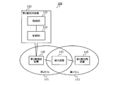
- FIG. 2A is a diagram illustrating an example of a communication system according to the second embodiment.
- the communication system 200 according to the second embodiment includes a core network 210, a macro cell base station 220, a small cell base station 230, and a mobile device 201.
- the communication system 200 is a communication system such as LTE defined by 3GPP (3rd Generation Partnership Project), for example.
- 1A and 1B can be realized by the communication system 200, for example.
- the first base station apparatus 110 shown in FIGS. 1A and 1B can be realized by the macro cell base station 220, for example.
- the 2nd base station apparatus 120 shown to FIG. 1A and FIG. 1B is realizable by the small cell base station 230, for example.
- 1A and 1B can be realized by the mobile device 201, for example.
- the host device 211 is a communication device included in the core network 210 and is a host device of the macro cell base station 220 and the small cell base station 230.
- the host device 211 is a SGW (Serving Gateway) or the like.
- the macro cell 221 is a cell formed by the macro cell base station 220.
- the macro cell base station 220 is, for example, an eNB (evolved Node B).
- the small cell 231 is a cell formed by the small cell base station 230.
- the small cell 231 is a cell having a smaller range than the macro cell 221 such as a femto cell, a pico cell, or a nano cell.
- the macro cell base station 220 and the small cell base station 230 are connected to the host device 211 of the core network 210 by S1 interfaces 241 and 242 respectively.
- the macro cell base station 220 and the small cell base station 230 are connected to each other by the X2 interface 243.
- the mobile device 201 is, for example, a UE (User Equipment: user terminal).
- the mobile device 201 can be connected to the macro cell base station 220 and the small cell base station 230. Further, the mobile device 201 can communicate with the macro cell base station 220 and the small cell base station 230 at the same time, and can receive different data (for example, U-Plane data) from the macro cell base station 220 and the small cell base station 230, respectively. .
- the host device 211 of the core network 210 transmits different data to the macro cell base station 220 and the small cell base station 230, respectively.
- the mobile device 201 performs communication simultaneously with the macro cell base station 220 and the small cell base station 230 at different frequencies.
- the higher-level device 211 may select a transfer path for data to be transmitted to the mobile device 201 according to the type of data.
- the host device 211 transmits data such as voice communication that requires more reliable communication than high throughput to the mobile device 201 via the macro cell base station 220.
- Voice communication is, for example, VoIP (Voice over IP), VoLTE (Voice over LTE), or the like.
- the host apparatus 211 transmits communication such as streaming that requires high throughput to the mobile device 201 via the small cell base station 230.
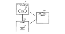
- FIG. 2B is a diagram illustrating an example of a protocol architecture.
- RRC 251 Radio Resource Control
- the RRC 252 is an RRC control unit in the mobile device 201.
- RRC between the macro cell base station 220 and the mobile device 201 is terminated by RRC 251 and 252 respectively. Also, RRC 251 and 252 terminate the RRC for communication of the mobile device 201 via the small cell base station 230. Thus, in the RRC 251 of the macro cell base station 220, both the U-Plane path of the macro cell 221 and the U-Plane path of the small cell 231 are managed.
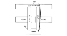
- FIGS. 3A and 3B are diagrams illustrating an example of bearer switching.
- a bearer # 1 using cell # 1 and a bearer # 2 using cell # 2 are set between the macro cell base station 220 and the mobile device 201. Is done. Then, for example, the macro cell base station 220 and the mobile device 201 switch from a state where communication is performed using the bearer # 1 as illustrated in FIG. 3A to a state where communication is performed using the bearer # 2 as illustrated in FIG. 3B. Switch bearer.
- communication can be continued by setting a plurality of bearers for the mobile device 201 and switching the bearers to be used at the time of cell switching.
- cell switching can be performed in a shorter time than handover.
- a plurality of bearers are set by duplicating the bearer of the mobile device 201 via the small cell base station 230 to the macro cell base station 220, and the bearer to be used is changed from the bearer of the small cell base station 230 to the macro cell. Switch to the bearer of base station 220. Thereby, cell switching in a short time becomes possible.
- FIG. 3C is a diagram illustrating an example of a U-Plane protocol stack.
- a protocol stack 330 illustrated in FIG. 3C is a U-Plane protocol stack in E-UTRAN (Evolved Universal Terrestrial Radio Access Network), for example.
- the above-described bearer replication can be performed by, for example, a PDCP (Packet Data Convergence Protocol) layer.
- PDCP Packet Data Convergence Protocol
- the mobile device shown in FIG. 3C is a mobile device 201, for example.
- the macro cell base station illustrated in FIG. 3C is, for example, a macro cell base station 220.
- the SGW illustrated in FIG. 3C is, for example, the host device 211.
- the server shown in FIG. 3C is a server that is provided in the core network 210 and communicates with the mobile device 201.
- FIG. 4 is a diagram illustrating an example of the operation of the communication system. 4, parts that are the same as the parts shown in FIG. 2A are given the same reference numerals, and descriptions thereof will be omitted.
- the macrocell base station 220 monitors the radio wave condition of communication using the small cell base station 230 by monitoring the measurement result of the radio wave condition transmitted from the mobile device 201.
- the mobile device 201 transmits the measurement result of the radio wave condition to the macro cell base station 220 at the time of position registration, for example. Further, the macro cell base station 220 periodically makes a request for measuring the radio wave condition to the mobile device 201, and the mobile machine 201 transmits the measurement result of the radio wave condition to the macro cell base station 220 in response to the measurement request.
- the macro cell base station 220 requests bearer information regarding the mobile device 201 from the small cell base station 230. Then, the macro cell base station 220 sets the same bearer as that of the small cell base station 230 in the macro cell base station 220.
- the small cell base station 230 replicates the data received from the core network 210 for transmission of each of the mobile device 201 and the macro cell base station 220. Then, the small cell base station 230 performs data transfer to the macro cell base station 220 in parallel with data transmission to the mobile device 201. This data transfer is performed via the X2 interface 243, for example.
- the macro cell base station 220 buffers the data transferred from the small cell base station 230 until bearer switching. Further, the macro cell base station 220 periodically monitors the radio wave condition, and deletes unnecessary buffering data when the measurement result of the radio wave condition does not fall below the second threshold (bearer switching threshold).
- the macro cell base station 220 When the measurement result of the radio wave condition falls below the second threshold value (bearer switching threshold value), the macro cell base station 220 performs bearer switching by making a bearer switching request to the core network 210 and transmits the buffering data to the mobile device. To 201. At this time, the macro cell base station 220 transmits data to the mobile device 201 while guaranteeing the order of the data transferred from the small cell base station 230 and the data transmitted from the core network 210. That is, the macro cell base station 220 transmits the data transmitted from the core network 210 after the bearer switching, after the transmission of the buffering data is completed.
- the second threshold value bearer switching threshold value
- the macro cell base station 220 deletes the bearer set in the macro cell base station 220 and deletes the buffering data.
- the macro cell base station 220 requests the small cell base station 230 to stop the copying and transferring.
- the deletion of the bearer and the deletion of the buffering data are performed after copying and transfer by a stop request, for example.
- FIG. 5 is a diagram illustrating an example of each threshold value.
- the vertical axis represents the radio wave condition.
- the radio wave status is a received radio wave intensity such as RSSI. The higher the received radio wave intensity, the better the radio wave condition, and the lower the received radio wave intensity, the worse the radio wave condition.
- the first threshold value, the second threshold value, and the third threshold value have, for example, a relationship of second threshold value ⁇ first threshold value ⁇ third threshold value.
- the first threshold value may be equal to the third threshold value.
- the first threshold value, the second threshold value, and the third threshold value are parameters that can be arbitrarily changed, for example, and may be parameters that can be individually set in a communication carrier, for example.
- the first threshold value is a threshold value for detecting deterioration of the radio wave condition of the small cell base station 230 and setting (duplicating) a bearer in the macro cell base station 220 in advance.
- the second threshold value is a threshold value for detecting deterioration of the radio wave condition of the small cell base station 230 and switching to the macro cell base station 220.
- the third threshold value is a threshold value for detecting the improvement of the radio wave condition of the small cell base station 230 and releasing the bearer set in the macro cell base station 220.
- Radio wave status changes 501 to 503 indicate changes in radio wave status reported from the mobile device 201. For example, when the radio wave condition falls below the first threshold as in the radio wave condition change 501, it can be determined that the communication situation in the small cell base station 230 has deteriorated. In this case, the small cell base station 230 starts data replication and transfer to the macro cell base station 220. On the other hand, the macro cell base station 220 copies the bearer of the macro cell base station 220 to the own station (secures radio resources), and starts buffering of transfer data from the macro cell base station 220.
- the macro cell base station 220 performs bearer switching for switching the bearer of the mobile device 201 from the small cell base station 230 to the macro cell base station 220. Thereby, the data transmission to the mobile device 201 can be continued.
- the macro cell base station 220 deletes the bearer set in the radio wave status change 501 (releases radio resources) and deletes buffering data.
- the small cell base station 230 stops data replication and transfer, and continues data transmission to the mobile device 201.
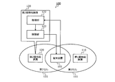
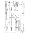
- FIG. 6A is a diagram illustrating an example of a configuration of each device of the communication system.
- 6B is a diagram illustrating an example of a signal flow in the configuration of each device of the communication system illustrated in FIG. 6A.
- the core network 210 includes a bearer management unit 611 and a data transmission unit 612.
- the bearer management unit 611 manages the U-Plane path of the macro cell base station 220 and the small cell base station 230.
- the data transmission unit 612 transmits data to the macro cell base station 220 and the small cell base station 230.
- the macro cell base station 220 includes a radio wave condition monitoring unit 621, a threshold management unit 622, a bearer management unit 623, a data management unit 624, a buffer 625, a data reception unit 626, and a data transmission unit 627.
- the radio wave status monitoring unit 621 periodically transmits a radio wave status measurement request to the mobile device 201. Further, the radio wave condition monitoring unit 621 receives the measurement result of the radio wave condition transmitted from the mobile device 201 in response to the measurement request. The radio wave status monitoring unit 621 outputs the received radio wave status measurement result to the threshold value management unit 622.
- the threshold management unit 622 stores the first threshold, the second threshold, and the third threshold described above.
- the threshold value management unit 622 compares the received radio wave intensity indicated by the radio wave condition measurement result output from the radio wave condition monitoring unit 621 with each threshold value, and outputs the comparison result to the bearer management unit 623 and the data management unit 624.
- the bearer management unit 623 manages bearers of the macro cell base station 220 and the small cell base station 230. Also, the bearer management unit 623 performs bearer setting of the macro cell base station 220 and a bearer switching request to the core network 210 based on the comparison result output from the threshold management unit 622.
- the data management unit 624 deletes the data buffered in the buffer 625 based on the comparison result output from the threshold management unit 622. Further, the data management unit 624 manages transmission of data buffered in the buffer 625 based on the comparison result output from the threshold management unit 622.
- the buffer 625 buffers each data output from the data receiving unit 626. Further, the buffer 625 deletes the buffering data and outputs the buffering data to the data transmission unit 627 under the control of the data management unit 624.
- the data receiving unit 626 receives data from the small cell base station 230. In addition, the data receiving unit 626 receives data from the core network 210. The data receiving unit 626 outputs the received data to the buffer 625. The data transmission unit 627 transmits the data output from the buffer 625 to the mobile device 201.
- the acquisition unit 122 illustrated in FIGS. 1A and 1B can be realized by the radio wave condition monitoring unit 621, for example.
- the control unit 123 illustrated in FIGS. 1A and 1B can be realized by, for example, a threshold management unit 622, a bearer management unit 623, a data management unit 624, a buffer 625, a data reception unit 626, and a data transmission unit 627.
- the small cell base station 230 includes a bearer management unit 631, a data reception unit 632, a data replication unit 633, and a data transmission unit 634.
- the bearer management unit 631 transmits bearer information regarding the mobile device 201 to the macro cell base station 220.
- the bearer management unit 631 when receiving the bearer deletion notification from the macro cell base station 220, the bearer management unit 631 outputs a data replication stop request for requesting stop of data replication to the data replication unit 633. Further, when a data transfer stop response indicating that the data transfer has been stopped is output from the data replication unit 633, the bearer management unit 631 sends a data transfer stop notification notifying that the data transfer has been stopped to the macro cell base station 220. Send.
- the data receiving unit 632 receives data from the core network 210 and outputs the received data to the data duplicating unit 633.
- the data duplicating unit 633 duplicates the data received from the core network 210 output from the data receiving unit 632 into two: data to the mobile device 201 and data to the macro cell base station 220. Then, the data replication unit 633 outputs the replicated data to the data transmission unit 634. The data transmission unit 634 transmits the data output from the data duplication unit 633 to the mobile device 201 and the macro cell base station 220.
- the mobile device 201 includes a radio wave state measuring unit 601 and a data receiving unit 602.
- the radio wave condition measurement unit 601 measures the radio wave condition based on the reception result of the wireless signal during communication, for example, at the time of location registration, and transmits the measurement result of the radio wave condition to the macro cell base station 220. Also, the radio wave condition measurement unit 601 measures the radio wave condition based on the reception result of the radio signal based on the radio wave condition measurement instruction from the macro cell base station 220 and transmits the radio wave condition measurement result to the macro cell base station 220. .
- the data receiving unit 602 receives data from the macro cell base station 220 and the small cell base station 230.
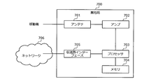
- FIG. 7A is a diagram illustrating an example of a hardware configuration of each base station.
- FIG. 7B is a diagram illustrating an example of a signal flow in the hardware configuration of each base station illustrated in FIG. 7A.
- Each of macro cell base station 220 and small cell base station 230 can be realized by base station 700 shown in FIGS. 7A and 7B, for example.
- the base station 700 includes an antenna 701, an amplifier 702, a processor 703, a memory 704, and a transmission path interface 705.
- the antenna 701 receives a signal wirelessly transmitted from another wireless communication device (for example, the mobile device 201), and outputs the received signal to the amplifier 702. Further, the antenna 701 wirelessly transmits the signal output from the amplifier 702 to another wireless communication device.
- another wireless communication device for example, the mobile device 201
- the antenna 701 wirelessly transmits the signal output from the amplifier 702 to another wireless communication device.
- the amplifier 702 amplifies the signal output from the antenna 701 and outputs the amplified signal to the processor 703.
- the amplifier 702 amplifies the signal output from the processor 703 and outputs the amplified signal to the antenna 701.
- the processor 703 controls the entire base station 700. For example, the processor 703 performs a transmission process of generating a signal to be transmitted to another wireless communication device and outputting the signal to the amplifier 702. The processor 703 performs reception processing such as demodulation and decoding of the signal output from the amplifier 702.
- the memory 704 includes, for example, a main memory and an auxiliary memory.
- the main memory is, for example, a RAM (Random Access Memory).
- the main memory is used as a work area for the memory 704.
- the auxiliary memory is, for example, a nonvolatile memory such as a magnetic disk, an optical disk, or a flash memory.
- Various programs for operating the base station 700 are stored in the auxiliary memory.
- the program stored in the auxiliary memory is loaded into the main memory and executed by the memory 704.
- the transmission path interface 705 is a communication interface that performs communication with the network 706 by, for example, a wired connection.
- the transmission path interface 705 includes an S1 interface with the core network 210 and an X2 interface between base stations.
- the transmission path interface 705 is controlled by the processor 703.
- the radio wave condition monitoring unit 621, threshold value management unit 622, bearer management unit 623, and data management unit 624 of the macro cell base station 220 shown in FIGS. 6A and 6B are realized by, for example, an antenna 701, an amplifier 702, a processor 703, and a memory 704. be able to.
- the data reception unit 626 and data transmission unit 627 of the macro cell base station 220 illustrated in FIGS. 6A and 6B can be realized by, for example, the antenna 701, the amplifier 702, the processor 703, and the memory 704.
- the buffer 625 of the macrocell base station 220 shown in FIGS. 6A and 6B can be realized by the processor 703 and the memory 704 (auxiliary memory), for example.
- the bearer management unit 631, the data reception unit 632, the data replication unit 633, and the data transmission unit 634 of the small cell base station 230 illustrated in FIGS. 6A and 6B can be realized by, for example, the processor 703 and the memory 704 (main memory). it can.
- FIG. 8A is a diagram illustrating an example of a hardware configuration of a mobile device.
- FIG. 8B is a diagram illustrating an example of a signal flow in the hardware configuration of the mobile device illustrated in FIG. 8A.
- the mobile device 201 can be realized by a mobile device 800 shown in FIGS. 8A and 8B, for example.
- Mobile device 800 includes antenna 801, amplifier 802, processor 803, and memory 804.
- the antenna 801 receives a signal wirelessly transmitted from another wireless communication device (for example, the macro cell base station 220 or the small cell base station 230), and outputs the received signal to the amplifier 802. Further, the antenna 801 wirelessly transmits the signal output from the amplifier 802 to another wireless communication device.
- another wireless communication device for example, the macro cell base station 220 or the small cell base station 230
- the amplifier 802 amplifies the signal output from the antenna 801 and outputs the amplified signal to the processor 803.
- the amplifier 802 amplifies the signal output from the processor 803 and outputs the amplified signal to the antenna 801.
- the processor 803 governs overall control of the mobile device 800. For example, the processor 803 performs a transmission process of generating a signal to be transmitted to another wireless communication device and outputting the signal to the amplifier 802. The processor 803 performs reception processing such as demodulation and decoding of the signal output from the amplifier 802.
- the memory 804 includes, for example, a main memory and an auxiliary memory.
- the main memory is, for example, a RAM.
- the main memory is used as a work area for the memory 804.
- the auxiliary memory is a non-volatile memory such as a magnetic disk or a flash memory.
- Various programs for operating the mobile device 800 are stored in the auxiliary memory.
- the program stored in the auxiliary memory is loaded into the main memory and executed by the memory 804.
- 6A and 6B can be realized by, for example, the processor 803 and the memory 804 (main memory).
- FIG. 9 is a diagram illustrating an example of information monitored by the radio wave condition monitoring unit.
- the radio wave condition monitoring unit of the macro cell base station 220 manages, for example, the radio wave condition monitoring table 900 shown in FIG.
- the radio wave status monitoring table 900 includes, as items, a mobile device identifier, a measurement time, and a received radio wave intensity.
- the mobile device identifier is an identifier of the target mobile device.
- the measurement time is the time when the measurement result of the radio wave condition is transmitted from the target mobile device. Alternatively, the measurement time may be a time when the radio wave condition is measured by the target mobile device.
- the received radio wave intensity is the radio wave intensity [dB] measured by the target mobile device.
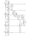
- Radio wave state management operation 10A and 10B are sequence diagrams illustrating an example of the radio wave condition management operation.
- the communication system 200 operates as each step shown in FIGS. 10A and 10B, for example, as the radio wave state management operation.
- FIG. 10A illustrates a case where the mobile device 201 voluntarily measures the radio wave condition.
- the radio wave condition measuring unit 601 of the mobile device 201 measures the radio wave condition based on the reception result of the radio signal, for example, at the time of position registration (step S1011).
- the radio wave state measuring unit 601 transmits the measurement result of step S1011 to the macro cell base station 220 (step S1012).
- the measurement result transmitted in step S1012 is information indicating, for example, the use frequency of mobile device 201 or the received radio wave intensity.
- RRC Measurement Report defined in 3GPP may be used as the measurement result.
- the radio wave condition monitoring unit 621 of the macrocell base station 220 stores the measurement result transmitted in step S1012 in the radio wave condition monitoring table 900 together with the time (measurement time) in step S1012 (see, for example, FIG. 9).
- FIG. 10B illustrates a case where the macro cell base station 220 periodically instructs measurement of the radio wave condition of the mobile device 201.
- the radio wave condition monitoring unit 621 of the macrocell base station 220 transmits a radio wave condition measurement instruction for instructing the mobile device 201 to measure the radio wave condition, for example, at a regular timing (step S1021).
- the radio wave condition measurement instruction transmitted in step S1021 is, for example, RRC Measurement Control.
- Step S1023 is the same as step S1012 shown in FIG. 10A.
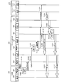
- FIG. 11 is a sequence diagram illustrating an example of bearer duplication operation.
- the communication system 200 operates as the bearer duplication operation, for example, in the steps illustrated in FIG.
- the radio wave condition monitoring unit 621 of the macro cell base station 220 receives the measurement result of the radio wave condition transmitted from the mobile device 201 (step S1101).
- Step S1101 corresponds to, for example, step S1012 shown in FIG. 10A and step S1023 shown in FIG. 10B.
- the radio wave status monitoring unit 621 notifies the threshold value management unit 622 of the radio wave status indicated by the measurement result received in step S1101 (step S1102).
- the threshold value management unit 622 determines the threshold value of the radio wave status (for example, received radio wave intensity) notified in step S1102 (step S1103). In the example shown in FIG. 11, it is assumed that the radio wave condition is less than the first threshold value. Next, the threshold value management unit 622 outputs a determination result indicating that the radio wave condition is less than the first threshold value to the bearer management unit 623 (step S1104).
- the bearer management unit 623 transmits a bearer information request for requesting bearer information regarding the mobile device 201 to the small cell base station 230 (step S1105).
- the bearer management unit 631 of the small cell base station 230 transmits bearer information related to the mobile device 201 to the macro cell base station 220 (step S1106).
- the bearer information is, for example, information indicating QoS (Quality of Service) such as QCI (QoS Class Identifier), PDCP sequence number, lower layer RLC (Radio Link Control) sequence number, and the like.
- QCI Quality of Service
- PDCP Packet Control Protocol
- RLC Radio Link Control
- the bearer management unit 623 of the macro cell base station 220 performs bearer setting of the mobile device 201 based on the bearer information transmitted in step S1106 (step S1107). Thereby, the bearer of the mobile device 201 set in the small cell base station 230 is copied to the macro cell base station 220.
- the data transmission unit 612 of the core network 210 transmits data for the mobile device 201 to the small cell base station 230 (step S1201).
- the data receiving unit 632 of the small cell base station 230 outputs the received data in step S1201 to the data duplicating unit 633 (step S1202).
- the data replication unit 633 performs data replication of the received data output from the data reception unit 632 (step S1203).
- the data replication unit 633 outputs the reception data (original data) output from the data reception unit 632 to the data transmission unit 634 (step S1204).
- the data transmission unit 634 transmits the original data output in step S1204 to the mobile device 201 (step S1205).
- the original data transmitted in step S1205 is received by the data receiving unit 602 of the mobile device 201.
- the buffer 625 deletes the buffering data based on the data deletion request output in step S1310 (step S1311).
- the macrocell base station 220 buffers the data transferred from the small cell base station 230 until bearer switching.
- the macro cell base station 220 sequentially deletes buffering data during a period in which the radio wave condition is equal to or greater than the second threshold.
- the buffering data during a period when the radio wave condition is equal to or greater than the second threshold is likely to reach the mobile device 201 from the small cell base station 230. Can be planned. Further, the amount of use of the buffer 625 can be reduced.
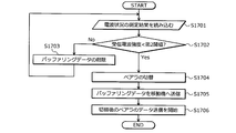
- the data management unit 624 outputs a data transmission request for requesting transmission of buffering data to the buffer 625 (step S1407).
- the buffer 625 outputs the buffering data to the data transmission unit 627 (step S1408).
- the data transmission unit 627 transmits the data (buffering data) output in step S1408 to the mobile device 201 (step S1409).
- the data transmitted in step S1409 is received by the data receiving unit 602 of the mobile device 201.
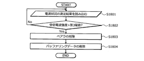
- the data replication unit 633 stops data replication and data transfer (step S1512).
- the data replication unit 633 stops the data replication in step S1203 shown in FIG. 12 and the data transfer in step S1206 shown in FIG.
- step S1602 when the received radio wave intensity is less than the first threshold (step S1602: Yes), the macro cell base station 220 copies the bearer of the mobile device 201 set in the small cell base station 230 to the own station. (Step S1603). Further, the macro cell base station 220 starts buffering of data transferred from the small cell base station 230 (step S1604).
- the macro cell base station 220 executes, for example, each step shown in FIG. 17 after step S1904 shown in FIG.
- the cell switching can be performed by switching the bearer to be used to the duplicate bearer. For this reason, cell switching can be performed in a short time, and throughput reduction during cell switching can be suppressed.
- Terminal device 110 1st base station apparatus 111 1st cell 120 2nd base station apparatus 121 2nd cell 122 Acquisition part 123 Control part 200 Communication system 201,800 Mobile device 210 Core network 211 Host apparatus 220 Macrocell base station 221 Macrocell 230 Small cell base station 231 Small cell 241 242 S1 interface 243 X2 interface 251 252 RRC 330 Protocol stack 501 to 503 Radio wave status change 601 Radio wave status measurement unit 602, 626, 632 Data reception unit 611, 623, 631 Bearer management unit 612, 627, 634 Data transmission unit 621 Radio wave status monitoring unit 622 Threshold management unit 624 Data management Section 625 Buffer 633 Data replication section 700 Base station 701, 801 Antenna 702, 802 Amplifier 703, 803 Processor 704, 804 Memory 705 Transmission path interface 706 Network 900 Radio wave condition monitoring table
Abstract
L'invention concerne un appareil terminal (101) qui se connecte à une première cellule (111) et à une seconde cellule (121) et qui effectue des communications à l'aide d'un premier support qui est défini dans la première cellule (111). Lorsque la qualité radio de la première cellule (111) dans l'appareil terminal (101) devient inférieure à une première valeur prédéterminée, un appareil de station de base (120) définit, dans la seconde cellule (121), un second support obtenue par duplication du premier support. Lorsque la qualité radio de la première cellule (111) dans l'appareil terminal (101) devient inférieure à une seconde valeur prédéterminée qui est inférieure à la première valeur prédéterminée, l'appareil de station de base (120) commute le support de communication de l'appareil terminal (101) du premier support au second support.
Priority Applications (3)
| Application Number | Priority Date | Filing Date | Title |
|---|---|---|---|
| PCT/JP2014/063256 WO2015177846A1 (fr) | 2014-05-19 | 2014-05-19 | Appareil de station de base et système |
| JP2016520826A JP6237897B2 (ja) | 2014-05-19 | 2014-05-19 | 基地局装置およびシステム |
| US15/346,290 US20170055191A1 (en) | 2014-05-19 | 2016-11-08 | Base station apparatus and system |
Applications Claiming Priority (1)
| Application Number | Priority Date | Filing Date | Title |
|---|---|---|---|
| PCT/JP2014/063256 WO2015177846A1 (fr) | 2014-05-19 | 2014-05-19 | Appareil de station de base et système |
Related Child Applications (1)
| Application Number | Title | Priority Date | Filing Date |
|---|---|---|---|
| US15/346,290 Continuation US20170055191A1 (en) | 2014-05-19 | 2016-11-08 | Base station apparatus and system |
Publications (1)
| Publication Number | Publication Date |
|---|---|
| WO2015177846A1 true WO2015177846A1 (fr) | 2015-11-26 |
Family
ID=54553544
Family Applications (1)
| Application Number | Title | Priority Date | Filing Date |
|---|---|---|---|
| PCT/JP2014/063256 WO2015177846A1 (fr) | 2014-05-19 | 2014-05-19 | Appareil de station de base et système |
Country Status (3)
| Country | Link |
|---|---|
| US (1) | US20170055191A1 (fr) |
| JP (1) | JP6237897B2 (fr) |
| WO (1) | WO2015177846A1 (fr) |
Cited By (1)
| Publication number | Priority date | Publication date | Assignee | Title |
|---|---|---|---|---|
| TWI763900B (zh) * | 2017-08-10 | 2022-05-11 | 美商高通公司 | 用於重複承載管理的技術和裝置 |
Families Citing this family (6)
| Publication number | Priority date | Publication date | Assignee | Title |
|---|---|---|---|---|
| KR102318015B1 (ko) | 2017-04-28 | 2021-10-27 | 삼성전자 주식회사 | 무선통신시스템에서 데이터 종류에 따른 길이를 지시하는 방법 및 장치 |
| RU2740161C1 (ru) | 2017-06-16 | 2021-01-12 | Гуандун Оппо Мобайл Телекоммьюникейшнс Корп., Лтд. | Способ передачи данных, оконечное устройство и сетевое устройство |
| CN109391951B (zh) * | 2017-08-02 | 2021-06-22 | 维沃移动通信有限公司 | 承载类型变换的方法和设备 |
| EP3641468B1 (fr) * | 2017-08-11 | 2021-10-06 | Guangdong Oppo Mobile Telecommunications Corp., Ltd. | Procédés de commande, noeuds, et supports de stockage informatique |
| US10893431B2 (en) | 2018-01-19 | 2021-01-12 | Asustek Computer Inc. | Method and apparatus for beam failure reporting under multicell configuration in a wireless communication system |
| CN110417520B (zh) * | 2018-04-27 | 2022-03-25 | 华为技术有限公司 | 通信方法和设备 |
Citations (6)
| Publication number | Priority date | Publication date | Assignee | Title |
|---|---|---|---|---|
| JP2002095031A (ja) * | 2000-08-04 | 2002-03-29 | Lucent Technol Inc | 通信リンクの個数の最適化方法 |
| JP2002159034A (ja) * | 2000-11-21 | 2002-05-31 | Canon Inc | 無線通信装置及び方法、並びに記憶媒体 |
| JP2002232929A (ja) * | 2001-02-01 | 2002-08-16 | Ntt Docomo Inc | ハンドオーバ制御方法、移動局及び通信制御装置 |
| JP2008103865A (ja) * | 2006-10-18 | 2008-05-01 | Nec Corp | ハンドオーバ制御システム及びその方法並びにそれを用いた移動通信システム及び無線基地局 |
| WO2008114751A1 (fr) * | 2007-03-16 | 2008-09-25 | Kyocera Corporation | Dispositif de communication radio et procédé de communication radio |
| JP2014075741A (ja) * | 2012-10-05 | 2014-04-24 | Nec Corp | 無線通信システム、基地局、移動局、通信制御方法、及びプログラム |
Family Cites Families (16)
| Publication number | Priority date | Publication date | Assignee | Title |
|---|---|---|---|---|
| US8228917B2 (en) * | 2005-04-26 | 2012-07-24 | Qualcomm Incorporated | Method and apparatus for ciphering and re-ordering packets in a wireless communication system |
| KR101203845B1 (ko) * | 2005-07-05 | 2012-11-21 | 엘지전자 주식회사 | 이동단말의 자원 관리가 가능한 매개체 무관 핸드오버를위한 메시지 송수신방법 |
| WO2007103369A2 (fr) * | 2006-03-07 | 2007-09-13 | Interdigital Technology Corporation | Procédé et appareil pour la prise en charge du transfert intercellulaire dans un système de communication sans fil lte gtp |
| WO2008066086A1 (fr) * | 2006-11-29 | 2008-06-05 | Kyocera Corporation | Terminal de radiocommunication et son procédé de commande |
| US8594069B2 (en) * | 2007-08-06 | 2013-11-26 | Qualcomm Incorporated | In-order data delivery during handover in a wireless communication system |
| US8085710B2 (en) * | 2007-08-23 | 2011-12-27 | Cisco Technology, Inc. | Minimizing packet loss during fast roaming |
| KR101344400B1 (ko) * | 2007-11-29 | 2014-02-17 | 삼성전자 주식회사 | 기지국간 핸드오버시의 패킷 포워딩 방법 |
| WO2012025158A1 (fr) * | 2010-08-27 | 2012-03-01 | Nokia Siemens Networks Oy | Transfert de connexion d'un équipement utilisateur |
| KR101702488B1 (ko) * | 2010-09-28 | 2017-02-03 | 주식회사 케이티 | 무선통신시스템에서 핸드오버 결정 방법 및 이를 위한 기지국 |
| CN103229558B (zh) * | 2010-12-03 | 2016-10-05 | 华为技术有限公司 | 异构网络中用户设备移动性支持的系统和方法 |
| CN102271374A (zh) * | 2011-09-14 | 2011-12-07 | 北京邮电大学 | 一种基于目标小区预承载的td-lte通信系统的快速切换方法 |
| US20130088960A1 (en) * | 2011-10-07 | 2013-04-11 | Futurewei Technologies, Inc. | System and Method for Information Delivery with Multiple Point Transmission |
| EP3668181A1 (fr) * | 2012-08-02 | 2020-06-17 | Telefonaktiebolaget LM Ericsson (publ) | Noeud et procédé de transfert d'un sous-ensemble de porteuses pour permettre de multiples connectivités d'un terminal vers plusieurs stations de base |
| KR102040883B1 (ko) * | 2012-08-23 | 2019-11-05 | 인터디지탈 패튼 홀딩스, 인크 | 무선 시스템에서의 다중 스케줄러들을 이용한 동작 |
| US9332473B2 (en) * | 2013-05-09 | 2016-05-03 | Sharp Kabushiki Kaisha | Systems and methods for re-establishing a connection |
| JP5977725B2 (ja) * | 2013-10-31 | 2016-08-24 | 株式会社Nttドコモ | 移動通信方法、移動局及び無線基地局 |
-
2014
- 2014-05-19 WO PCT/JP2014/063256 patent/WO2015177846A1/fr active Application Filing
- 2014-05-19 JP JP2016520826A patent/JP6237897B2/ja not_active Expired - Fee Related
-
2016
- 2016-11-08 US US15/346,290 patent/US20170055191A1/en not_active Abandoned
Patent Citations (6)
| Publication number | Priority date | Publication date | Assignee | Title |
|---|---|---|---|---|
| JP2002095031A (ja) * | 2000-08-04 | 2002-03-29 | Lucent Technol Inc | 通信リンクの個数の最適化方法 |
| JP2002159034A (ja) * | 2000-11-21 | 2002-05-31 | Canon Inc | 無線通信装置及び方法、並びに記憶媒体 |
| JP2002232929A (ja) * | 2001-02-01 | 2002-08-16 | Ntt Docomo Inc | ハンドオーバ制御方法、移動局及び通信制御装置 |
| JP2008103865A (ja) * | 2006-10-18 | 2008-05-01 | Nec Corp | ハンドオーバ制御システム及びその方法並びにそれを用いた移動通信システム及び無線基地局 |
| WO2008114751A1 (fr) * | 2007-03-16 | 2008-09-25 | Kyocera Corporation | Dispositif de communication radio et procédé de communication radio |
| JP2014075741A (ja) * | 2012-10-05 | 2014-04-24 | Nec Corp | 無線通信システム、基地局、移動局、通信制御方法、及びプログラム |
Cited By (1)
| Publication number | Priority date | Publication date | Assignee | Title |
|---|---|---|---|---|
| TWI763900B (zh) * | 2017-08-10 | 2022-05-11 | 美商高通公司 | 用於重複承載管理的技術和裝置 |
Also Published As
| Publication number | Publication date |
|---|---|
| JPWO2015177846A1 (ja) | 2017-04-20 |
| US20170055191A1 (en) | 2017-02-23 |
| JP6237897B2 (ja) | 2017-11-29 |
Similar Documents
| Publication | Publication Date | Title |
|---|---|---|
| JP6237897B2 (ja) | 基地局装置およびシステム | |
| US20240155440A1 (en) | Long term evolution radio access network | |
| US10425876B2 (en) | Data forwarding method, device, and communications system | |
| CN104509167B (zh) | 通信网络中用于将无线终端连接到多个小区的方法 | |
| KR102157188B1 (ko) | Lte 네트워크에서의 이동 단말 핸드오버 | |
| KR102155523B1 (ko) | 이중 연결을 지원하는 무선 통신 시스템에서 단말과 기지국 사이의 연결 구성 결정 및 핸드 오버 수행 방법 및 장치 | |
| US9380618B2 (en) | Base station, user equipment, and communications method | |
| US9807658B2 (en) | Cell handover method and apparatus | |
| JP6146832B2 (ja) | デバイス間通信のハンドオーバのための方法及び装置 | |
| WO2015184889A1 (fr) | Procédé de commutation de station de base par un équipement d'utilisateur, station de base et équipement d'utilisateur | |
| JP2023504476A (ja) | セル管理方法、装置、機器及び記憶媒体 | |
| JP2017507581A (ja) | ユーザ機器のハンドオーバにサービスを提供するための方法、基地局、および二重接続性システム | |
| CN106941700B (zh) | 一种数据传输方法及装置和基站及ue | |
| KR20170043533A (ko) | 인터/인트라 무선 액세스 기술 이동성 및 사용자 평면 스플릿 측정 구성 | |
| CN102883441A (zh) | 一种无线宽带通信方法,装置和系统 | |
| CN102883440A (zh) | 一种无线宽带通信方法,装置和系统 | |
| JP2015513264A (ja) | 移動通信のための物理レイヤおよびリンクレイヤにおける方法および装置 | |
| JP2012525720A (ja) | モバイルネットワーク、無線アクセスノード、リレー装置を含むシステム、およびその方法 | |
| JP5930442B2 (ja) | マルチモード無線通信システムを制御するための方法、制御サーバ、及び端末 | |
| JP6290413B2 (ja) | 接続管理方法及びアクセスネットワークエレメント | |
| EP3267724A1 (fr) | Procédé de transmission de données destiné à être utilisé pendant le transfert d'une station de base, dispositif d'utilisateur et station de base, et support de stockage | |
| WO2017177950A1 (fr) | Procédé, appareil et système d'établissement de connexion | |
| US20150124762A1 (en) | Method for reducing overhead of control signal during connection of plural lte base stations | |
| EP2836011B1 (fr) | Appareils, procédés et programmes informatiques pour des émetteurs-récepteurs de station de base et un émetteur-récepteur mobile se rapportant à un changement de la réception de données de charge utile | |
| US9781635B2 (en) | Base station providing handover among small cells |
Legal Events
| Date | Code | Title | Description |
|---|---|---|---|
| 121 | Ep: the epo has been informed by wipo that ep was designated in this application |
Ref document number: 14892241 Country of ref document: EP Kind code of ref document: A1 |
|
| ENP | Entry into the national phase |
Ref document number: 2016520826 Country of ref document: JP Kind code of ref document: A |
|
| NENP | Non-entry into the national phase |
Ref country code: DE |
|
| 122 | Ep: pct application non-entry in european phase |
Ref document number: 14892241 Country of ref document: EP Kind code of ref document: A1 |