WO2015177846A1 - Base station apparatus and system - Google Patents
Base station apparatus and system Download PDFInfo
- Publication number
- WO2015177846A1 WO2015177846A1 PCT/JP2014/063256 JP2014063256W WO2015177846A1 WO 2015177846 A1 WO2015177846 A1 WO 2015177846A1 JP 2014063256 W JP2014063256 W JP 2014063256W WO 2015177846 A1 WO2015177846 A1 WO 2015177846A1
- Authority
- WO
- WIPO (PCT)
- Prior art keywords
- bearer
- base station
- data
- cell
- terminal device
- Prior art date
Links
Images


Classifications
-
- H—ELECTRICITY
- H04—ELECTRIC COMMUNICATION TECHNIQUE
- H04W—WIRELESS COMMUNICATION NETWORKS
- H04W36/00—Hand-off or reselection arrangements
- H04W36/04—Reselecting a cell layer in multi-layered cells
-
- H—ELECTRICITY
- H04—ELECTRIC COMMUNICATION TECHNIQUE
- H04W—WIRELESS COMMUNICATION NETWORKS
- H04W16/00—Network planning, e.g. coverage or traffic planning tools; Network deployment, e.g. resource partitioning or cells structures
- H04W16/24—Cell structures
- H04W16/32—Hierarchical cell structures
-
- H—ELECTRICITY
- H04—ELECTRIC COMMUNICATION TECHNIQUE
- H04W—WIRELESS COMMUNICATION NETWORKS
- H04W36/00—Hand-off or reselection arrangements
- H04W36/16—Performing reselection for specific purposes
- H04W36/18—Performing reselection for specific purposes for allowing seamless reselection, e.g. soft reselection
-
- H—ELECTRICITY
- H04—ELECTRIC COMMUNICATION TECHNIQUE
- H04W—WIRELESS COMMUNICATION NETWORKS
- H04W36/00—Hand-off or reselection arrangements
- H04W36/24—Reselection being triggered by specific parameters
- H04W36/30—Reselection being triggered by specific parameters by measured or perceived connection quality data
-
- H—ELECTRICITY
- H04—ELECTRIC COMMUNICATION TECHNIQUE
- H04W—WIRELESS COMMUNICATION NETWORKS
- H04W36/00—Hand-off or reselection arrangements
- H04W36/02—Buffering or recovering information during reselection ; Modification of the traffic flow during hand-off
- H04W36/023—Buffering or recovering information during reselection
Definitions
- an object of the present invention is to provide a base station apparatus and system that can suppress a decrease in throughput during cell switching.
- FIG. 6A is a diagram illustrating an example of a configuration of each device of the communication system.
- 6B is a diagram illustrating an example of a signal flow in the configuration of each device of the communication system illustrated in FIG. 6A.
- FIG. 7A is a diagram illustrating an example of a hardware configuration of each base station.
- FIG. 7B is a diagram illustrating an example of a signal flow in the hardware configuration of each base station illustrated in FIG. 7A.
- FIG. 8A is a diagram illustrating an example of a hardware configuration of a mobile device.
- FIG. 8B is a diagram illustrating an example of a signal flow in the hardware configuration of the mobile device illustrated in FIG. 8A.
- FIG. 9 is a diagram illustrating an example of information monitored by the radio wave condition monitoring unit.
- FIG. 9 is a diagram illustrating an example of information monitored by the radio wave condition monitoring unit.
- the 2nd base station apparatus 120 demonstrated the structure provided with the acquisition part 122 and the control part 123, it is good also as a structure with which the 1st base station apparatus 110 is provided with the acquisition part 122 and the control part 123.
- the wireless quality information includes information indicating that the wireless quality information related to the wireless quality is equal to or less than a first predetermined value, and wireless quality information related to the wireless quality. May be information indicating that is less than or equal to the second predetermined value.
- the control unit 123 may control the following buffering when the radio quality of the first cell 111 in the terminal device 101 is lower than the first predetermined value and the duplicate bearer is set in the second cell 121. That is, the control unit 123 causes the first base station device 110 to transmit the duplicate data of the data that the first cell 111 transmits to the terminal device 101 by the first bearer to the second base station device 120, and the second base station device 120. Control may be performed to buffer the replicated data.
- the control unit 123 performs the following control when the radio quality of the first cell 111 in the terminal device 101 falls below the second predetermined value and the bearer used for communication of the terminal device 101 is switched to the duplicate bearer. That is, the control unit 123 causes the second base station apparatus 120 to transmit the duplicated data that has been buffered to the terminal apparatus 101 using the second bearer. Thereby, the data transmission by a 2nd bearer can be started in a short time at the time of bearer switching. For this reason, it is possible to suppress a decrease in throughput during cell switching.
- the control unit 123 is configured such that the radio quality of the first cell 111 in the terminal device 101 is not lower than the second predetermined value among the duplicated data buffered from the duplicated data transmitted by the second base station device 120 after bearer switching. It may be replicated data up to the point in time. Thereby, it is possible to prevent the terminal device 101 from transmitting again from the second cell 121 data that is highly likely to be normally received from the first cell 111.
- the control unit 123 buffers the second base station device 120. You may perform control to delete replication data sequentially. Thereby, the amount of memory used for buffering in the second base station apparatus 120 can be reduced.
- control unit 123 when the radio quality of the first cell 111 in the terminal device 101 exceeds the first predetermined value and then exceeds the third predetermined value, the first base station device 110 to the second base station device 120. You may perform control which stops transmission of the replication data to. Thereby, when the radio quality of the 1st cell 111 in the terminal device 101 improves, the traffic between the 1st base station apparatus 110 and the 2nd base station apparatus 120 can be reduced.
- the bearer of the terminal device 101 established in the first cell 111 may be copied to the second cell 121. Good. And when the deterioration of the wireless quality of the 1st cell 111 in the terminal device 101 is detected, the bearer used for the communication of the terminal device 101 is switched to a replication bearer.
- the bearer of the terminal device 101 can be copied to the second cell 121 before the wireless quality of the first cell 111 in the terminal device 101 deteriorates due to the movement of the terminal device 101. Therefore, for example, cell switching can be performed by switching a bearer to be used to a duplicate bearer without performing bearer movement at the time of cell switching. For this reason, cell switching can be performed in a short time, and throughput reduction during cell switching can be suppressed.
- the information acquired by the acquisition unit 122 may be information indicating that the movement speed exceeds a predetermined speed. .
- control unit 123 duplicates the first bearer of the terminal device 101 set in the first cell 111 when the moving speed of the terminal device 101 exceeds the predetermined speed and the wireless quality falls below the first predetermined value.
- the second bearer may be set in the second cell 121.
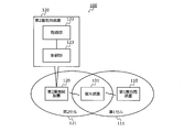
- FIG. 2A is a diagram illustrating an example of a communication system according to the second embodiment.
- the communication system 200 according to the second embodiment includes a core network 210, a macro cell base station 220, a small cell base station 230, and a mobile device 201.
- the communication system 200 is a communication system such as LTE defined by 3GPP (3rd Generation Partnership Project), for example.
- 1A and 1B can be realized by the communication system 200, for example.
- the first base station apparatus 110 shown in FIGS. 1A and 1B can be realized by the macro cell base station 220, for example.
- the 2nd base station apparatus 120 shown to FIG. 1A and FIG. 1B is realizable by the small cell base station 230, for example.
- 1A and 1B can be realized by the mobile device 201, for example.
- the host device 211 is a communication device included in the core network 210 and is a host device of the macro cell base station 220 and the small cell base station 230.
- the host device 211 is a SGW (Serving Gateway) or the like.
- the macro cell 221 is a cell formed by the macro cell base station 220.
- the macro cell base station 220 is, for example, an eNB (evolved Node B).
- the small cell 231 is a cell formed by the small cell base station 230.
- the small cell 231 is a cell having a smaller range than the macro cell 221 such as a femto cell, a pico cell, or a nano cell.
- the macro cell base station 220 and the small cell base station 230 are connected to the host device 211 of the core network 210 by S1 interfaces 241 and 242 respectively.
- the macro cell base station 220 and the small cell base station 230 are connected to each other by the X2 interface 243.
- the mobile device 201 is, for example, a UE (User Equipment: user terminal).
- the mobile device 201 can be connected to the macro cell base station 220 and the small cell base station 230. Further, the mobile device 201 can communicate with the macro cell base station 220 and the small cell base station 230 at the same time, and can receive different data (for example, U-Plane data) from the macro cell base station 220 and the small cell base station 230, respectively. .
- the host device 211 of the core network 210 transmits different data to the macro cell base station 220 and the small cell base station 230, respectively.
- the mobile device 201 performs communication simultaneously with the macro cell base station 220 and the small cell base station 230 at different frequencies.
- the higher-level device 211 may select a transfer path for data to be transmitted to the mobile device 201 according to the type of data.
- the host device 211 transmits data such as voice communication that requires more reliable communication than high throughput to the mobile device 201 via the macro cell base station 220.
- Voice communication is, for example, VoIP (Voice over IP), VoLTE (Voice over LTE), or the like.
- the host apparatus 211 transmits communication such as streaming that requires high throughput to the mobile device 201 via the small cell base station 230.
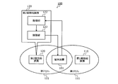
- FIG. 2B is a diagram illustrating an example of a protocol architecture.
- RRC 251 Radio Resource Control
- the RRC 252 is an RRC control unit in the mobile device 201.
- RRC between the macro cell base station 220 and the mobile device 201 is terminated by RRC 251 and 252 respectively. Also, RRC 251 and 252 terminate the RRC for communication of the mobile device 201 via the small cell base station 230. Thus, in the RRC 251 of the macro cell base station 220, both the U-Plane path of the macro cell 221 and the U-Plane path of the small cell 231 are managed.
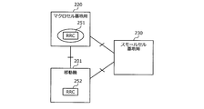
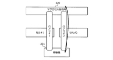
- FIGS. 3A and 3B are diagrams illustrating an example of bearer switching.
- a bearer # 1 using cell # 1 and a bearer # 2 using cell # 2 are set between the macro cell base station 220 and the mobile device 201. Is done. Then, for example, the macro cell base station 220 and the mobile device 201 switch from a state where communication is performed using the bearer # 1 as illustrated in FIG. 3A to a state where communication is performed using the bearer # 2 as illustrated in FIG. 3B. Switch bearer.
- communication can be continued by setting a plurality of bearers for the mobile device 201 and switching the bearers to be used at the time of cell switching.
- cell switching can be performed in a shorter time than handover.
- a plurality of bearers are set by duplicating the bearer of the mobile device 201 via the small cell base station 230 to the macro cell base station 220, and the bearer to be used is changed from the bearer of the small cell base station 230 to the macro cell. Switch to the bearer of base station 220. Thereby, cell switching in a short time becomes possible.
- FIG. 3C is a diagram illustrating an example of a U-Plane protocol stack.
- a protocol stack 330 illustrated in FIG. 3C is a U-Plane protocol stack in E-UTRAN (Evolved Universal Terrestrial Radio Access Network), for example.
- the above-described bearer replication can be performed by, for example, a PDCP (Packet Data Convergence Protocol) layer.
- PDCP Packet Data Convergence Protocol
- the mobile device shown in FIG. 3C is a mobile device 201, for example.
- the macro cell base station illustrated in FIG. 3C is, for example, a macro cell base station 220.
- the SGW illustrated in FIG. 3C is, for example, the host device 211.
- the server shown in FIG. 3C is a server that is provided in the core network 210 and communicates with the mobile device 201.
- FIG. 4 is a diagram illustrating an example of the operation of the communication system. 4, parts that are the same as the parts shown in FIG. 2A are given the same reference numerals, and descriptions thereof will be omitted.
- the macrocell base station 220 monitors the radio wave condition of communication using the small cell base station 230 by monitoring the measurement result of the radio wave condition transmitted from the mobile device 201.
- the mobile device 201 transmits the measurement result of the radio wave condition to the macro cell base station 220 at the time of position registration, for example. Further, the macro cell base station 220 periodically makes a request for measuring the radio wave condition to the mobile device 201, and the mobile machine 201 transmits the measurement result of the radio wave condition to the macro cell base station 220 in response to the measurement request.
- the macro cell base station 220 requests bearer information regarding the mobile device 201 from the small cell base station 230. Then, the macro cell base station 220 sets the same bearer as that of the small cell base station 230 in the macro cell base station 220.
- the small cell base station 230 replicates the data received from the core network 210 for transmission of each of the mobile device 201 and the macro cell base station 220. Then, the small cell base station 230 performs data transfer to the macro cell base station 220 in parallel with data transmission to the mobile device 201. This data transfer is performed via the X2 interface 243, for example.
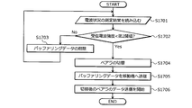
- the macro cell base station 220 buffers the data transferred from the small cell base station 230 until bearer switching. Further, the macro cell base station 220 periodically monitors the radio wave condition, and deletes unnecessary buffering data when the measurement result of the radio wave condition does not fall below the second threshold (bearer switching threshold).
- the macro cell base station 220 When the measurement result of the radio wave condition falls below the second threshold value (bearer switching threshold value), the macro cell base station 220 performs bearer switching by making a bearer switching request to the core network 210 and transmits the buffering data to the mobile device. To 201. At this time, the macro cell base station 220 transmits data to the mobile device 201 while guaranteeing the order of the data transferred from the small cell base station 230 and the data transmitted from the core network 210. That is, the macro cell base station 220 transmits the data transmitted from the core network 210 after the bearer switching, after the transmission of the buffering data is completed.
- the second threshold value bearer switching threshold value
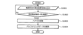
- the macro cell base station 220 deletes the bearer set in the macro cell base station 220 and deletes the buffering data.
- the macro cell base station 220 requests the small cell base station 230 to stop the copying and transferring.
- the deletion of the bearer and the deletion of the buffering data are performed after copying and transfer by a stop request, for example.
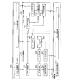
- FIG. 5 is a diagram illustrating an example of each threshold value.
- the vertical axis represents the radio wave condition.
- the radio wave status is a received radio wave intensity such as RSSI. The higher the received radio wave intensity, the better the radio wave condition, and the lower the received radio wave intensity, the worse the radio wave condition.
- the first threshold value, the second threshold value, and the third threshold value have, for example, a relationship of second threshold value ⁇ first threshold value ⁇ third threshold value.
- the first threshold value may be equal to the third threshold value.
- the first threshold value, the second threshold value, and the third threshold value are parameters that can be arbitrarily changed, for example, and may be parameters that can be individually set in a communication carrier, for example.
- the first threshold value is a threshold value for detecting deterioration of the radio wave condition of the small cell base station 230 and setting (duplicating) a bearer in the macro cell base station 220 in advance.
- the second threshold value is a threshold value for detecting deterioration of the radio wave condition of the small cell base station 230 and switching to the macro cell base station 220.
- the third threshold value is a threshold value for detecting the improvement of the radio wave condition of the small cell base station 230 and releasing the bearer set in the macro cell base station 220.
- Radio wave status changes 501 to 503 indicate changes in radio wave status reported from the mobile device 201. For example, when the radio wave condition falls below the first threshold as in the radio wave condition change 501, it can be determined that the communication situation in the small cell base station 230 has deteriorated. In this case, the small cell base station 230 starts data replication and transfer to the macro cell base station 220. On the other hand, the macro cell base station 220 copies the bearer of the macro cell base station 220 to the own station (secures radio resources), and starts buffering of transfer data from the macro cell base station 220.
- the macro cell base station 220 performs bearer switching for switching the bearer of the mobile device 201 from the small cell base station 230 to the macro cell base station 220. Thereby, the data transmission to the mobile device 201 can be continued.
- the macro cell base station 220 deletes the bearer set in the radio wave status change 501 (releases radio resources) and deletes buffering data.
- the small cell base station 230 stops data replication and transfer, and continues data transmission to the mobile device 201.
- FIG. 6A is a diagram illustrating an example of a configuration of each device of the communication system.
- 6B is a diagram illustrating an example of a signal flow in the configuration of each device of the communication system illustrated in FIG. 6A.
- the core network 210 includes a bearer management unit 611 and a data transmission unit 612.
- the bearer management unit 611 manages the U-Plane path of the macro cell base station 220 and the small cell base station 230.
- the data transmission unit 612 transmits data to the macro cell base station 220 and the small cell base station 230.
- the macro cell base station 220 includes a radio wave condition monitoring unit 621, a threshold management unit 622, a bearer management unit 623, a data management unit 624, a buffer 625, a data reception unit 626, and a data transmission unit 627.
- the radio wave status monitoring unit 621 periodically transmits a radio wave status measurement request to the mobile device 201. Further, the radio wave condition monitoring unit 621 receives the measurement result of the radio wave condition transmitted from the mobile device 201 in response to the measurement request. The radio wave status monitoring unit 621 outputs the received radio wave status measurement result to the threshold value management unit 622.
- the threshold management unit 622 stores the first threshold, the second threshold, and the third threshold described above.
- the threshold value management unit 622 compares the received radio wave intensity indicated by the radio wave condition measurement result output from the radio wave condition monitoring unit 621 with each threshold value, and outputs the comparison result to the bearer management unit 623 and the data management unit 624.
- the bearer management unit 623 manages bearers of the macro cell base station 220 and the small cell base station 230. Also, the bearer management unit 623 performs bearer setting of the macro cell base station 220 and a bearer switching request to the core network 210 based on the comparison result output from the threshold management unit 622.
- the data management unit 624 deletes the data buffered in the buffer 625 based on the comparison result output from the threshold management unit 622. Further, the data management unit 624 manages transmission of data buffered in the buffer 625 based on the comparison result output from the threshold management unit 622.
- the buffer 625 buffers each data output from the data receiving unit 626. Further, the buffer 625 deletes the buffering data and outputs the buffering data to the data transmission unit 627 under the control of the data management unit 624.
- the data receiving unit 626 receives data from the small cell base station 230. In addition, the data receiving unit 626 receives data from the core network 210. The data receiving unit 626 outputs the received data to the buffer 625. The data transmission unit 627 transmits the data output from the buffer 625 to the mobile device 201.
- the acquisition unit 122 illustrated in FIGS. 1A and 1B can be realized by the radio wave condition monitoring unit 621, for example.
- the control unit 123 illustrated in FIGS. 1A and 1B can be realized by, for example, a threshold management unit 622, a bearer management unit 623, a data management unit 624, a buffer 625, a data reception unit 626, and a data transmission unit 627.
- the small cell base station 230 includes a bearer management unit 631, a data reception unit 632, a data replication unit 633, and a data transmission unit 634.
- the bearer management unit 631 transmits bearer information regarding the mobile device 201 to the macro cell base station 220.
- the bearer management unit 631 when receiving the bearer deletion notification from the macro cell base station 220, the bearer management unit 631 outputs a data replication stop request for requesting stop of data replication to the data replication unit 633. Further, when a data transfer stop response indicating that the data transfer has been stopped is output from the data replication unit 633, the bearer management unit 631 sends a data transfer stop notification notifying that the data transfer has been stopped to the macro cell base station 220. Send.
- the data receiving unit 632 receives data from the core network 210 and outputs the received data to the data duplicating unit 633.
- the data duplicating unit 633 duplicates the data received from the core network 210 output from the data receiving unit 632 into two: data to the mobile device 201 and data to the macro cell base station 220. Then, the data replication unit 633 outputs the replicated data to the data transmission unit 634. The data transmission unit 634 transmits the data output from the data duplication unit 633 to the mobile device 201 and the macro cell base station 220.
- the mobile device 201 includes a radio wave state measuring unit 601 and a data receiving unit 602.
- the radio wave condition measurement unit 601 measures the radio wave condition based on the reception result of the wireless signal during communication, for example, at the time of location registration, and transmits the measurement result of the radio wave condition to the macro cell base station 220. Also, the radio wave condition measurement unit 601 measures the radio wave condition based on the reception result of the radio signal based on the radio wave condition measurement instruction from the macro cell base station 220 and transmits the radio wave condition measurement result to the macro cell base station 220. .
- the data receiving unit 602 receives data from the macro cell base station 220 and the small cell base station 230.
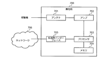
- FIG. 7A is a diagram illustrating an example of a hardware configuration of each base station.
- FIG. 7B is a diagram illustrating an example of a signal flow in the hardware configuration of each base station illustrated in FIG. 7A.
- Each of macro cell base station 220 and small cell base station 230 can be realized by base station 700 shown in FIGS. 7A and 7B, for example.
- the base station 700 includes an antenna 701, an amplifier 702, a processor 703, a memory 704, and a transmission path interface 705.
- the antenna 701 receives a signal wirelessly transmitted from another wireless communication device (for example, the mobile device 201), and outputs the received signal to the amplifier 702. Further, the antenna 701 wirelessly transmits the signal output from the amplifier 702 to another wireless communication device.
- another wireless communication device for example, the mobile device 201
- the antenna 701 wirelessly transmits the signal output from the amplifier 702 to another wireless communication device.
- the amplifier 702 amplifies the signal output from the antenna 701 and outputs the amplified signal to the processor 703.
- the amplifier 702 amplifies the signal output from the processor 703 and outputs the amplified signal to the antenna 701.
- the processor 703 controls the entire base station 700. For example, the processor 703 performs a transmission process of generating a signal to be transmitted to another wireless communication device and outputting the signal to the amplifier 702. The processor 703 performs reception processing such as demodulation and decoding of the signal output from the amplifier 702.
- the memory 704 includes, for example, a main memory and an auxiliary memory.
- the main memory is, for example, a RAM (Random Access Memory).
- the main memory is used as a work area for the memory 704.
- the auxiliary memory is, for example, a nonvolatile memory such as a magnetic disk, an optical disk, or a flash memory.
- Various programs for operating the base station 700 are stored in the auxiliary memory.
- the program stored in the auxiliary memory is loaded into the main memory and executed by the memory 704.
- the transmission path interface 705 is a communication interface that performs communication with the network 706 by, for example, a wired connection.
- the transmission path interface 705 includes an S1 interface with the core network 210 and an X2 interface between base stations.
- the transmission path interface 705 is controlled by the processor 703.
- the radio wave condition monitoring unit 621, threshold value management unit 622, bearer management unit 623, and data management unit 624 of the macro cell base station 220 shown in FIGS. 6A and 6B are realized by, for example, an antenna 701, an amplifier 702, a processor 703, and a memory 704. be able to.
- the data reception unit 626 and data transmission unit 627 of the macro cell base station 220 illustrated in FIGS. 6A and 6B can be realized by, for example, the antenna 701, the amplifier 702, the processor 703, and the memory 704.
- the buffer 625 of the macrocell base station 220 shown in FIGS. 6A and 6B can be realized by the processor 703 and the memory 704 (auxiliary memory), for example.
- the bearer management unit 631, the data reception unit 632, the data replication unit 633, and the data transmission unit 634 of the small cell base station 230 illustrated in FIGS. 6A and 6B can be realized by, for example, the processor 703 and the memory 704 (main memory). it can.
- FIG. 8A is a diagram illustrating an example of a hardware configuration of a mobile device.
- FIG. 8B is a diagram illustrating an example of a signal flow in the hardware configuration of the mobile device illustrated in FIG. 8A.
- the mobile device 201 can be realized by a mobile device 800 shown in FIGS. 8A and 8B, for example.
- Mobile device 800 includes antenna 801, amplifier 802, processor 803, and memory 804.
- the antenna 801 receives a signal wirelessly transmitted from another wireless communication device (for example, the macro cell base station 220 or the small cell base station 230), and outputs the received signal to the amplifier 802. Further, the antenna 801 wirelessly transmits the signal output from the amplifier 802 to another wireless communication device.
- another wireless communication device for example, the macro cell base station 220 or the small cell base station 230
- the amplifier 802 amplifies the signal output from the antenna 801 and outputs the amplified signal to the processor 803.
- the amplifier 802 amplifies the signal output from the processor 803 and outputs the amplified signal to the antenna 801.
- the processor 803 governs overall control of the mobile device 800. For example, the processor 803 performs a transmission process of generating a signal to be transmitted to another wireless communication device and outputting the signal to the amplifier 802. The processor 803 performs reception processing such as demodulation and decoding of the signal output from the amplifier 802.
- the memory 804 includes, for example, a main memory and an auxiliary memory.
- the main memory is, for example, a RAM.
- the main memory is used as a work area for the memory 804.
- the auxiliary memory is a non-volatile memory such as a magnetic disk or a flash memory.
- Various programs for operating the mobile device 800 are stored in the auxiliary memory.
- the program stored in the auxiliary memory is loaded into the main memory and executed by the memory 804.
- 6A and 6B can be realized by, for example, the processor 803 and the memory 804 (main memory).
- FIG. 9 is a diagram illustrating an example of information monitored by the radio wave condition monitoring unit.
- the radio wave condition monitoring unit of the macro cell base station 220 manages, for example, the radio wave condition monitoring table 900 shown in FIG.
- the radio wave status monitoring table 900 includes, as items, a mobile device identifier, a measurement time, and a received radio wave intensity.
- the mobile device identifier is an identifier of the target mobile device.
- the measurement time is the time when the measurement result of the radio wave condition is transmitted from the target mobile device. Alternatively, the measurement time may be a time when the radio wave condition is measured by the target mobile device.
- the received radio wave intensity is the radio wave intensity [dB] measured by the target mobile device.
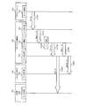
- Radio wave state management operation 10A and 10B are sequence diagrams illustrating an example of the radio wave condition management operation.
- the communication system 200 operates as each step shown in FIGS. 10A and 10B, for example, as the radio wave state management operation.
- FIG. 10A illustrates a case where the mobile device 201 voluntarily measures the radio wave condition.
- the radio wave condition measuring unit 601 of the mobile device 201 measures the radio wave condition based on the reception result of the radio signal, for example, at the time of position registration (step S1011).
- the radio wave state measuring unit 601 transmits the measurement result of step S1011 to the macro cell base station 220 (step S1012).
- the measurement result transmitted in step S1012 is information indicating, for example, the use frequency of mobile device 201 or the received radio wave intensity.
- RRC Measurement Report defined in 3GPP may be used as the measurement result.
- the radio wave condition monitoring unit 621 of the macrocell base station 220 stores the measurement result transmitted in step S1012 in the radio wave condition monitoring table 900 together with the time (measurement time) in step S1012 (see, for example, FIG. 9).
- FIG. 10B illustrates a case where the macro cell base station 220 periodically instructs measurement of the radio wave condition of the mobile device 201.
- the radio wave condition monitoring unit 621 of the macrocell base station 220 transmits a radio wave condition measurement instruction for instructing the mobile device 201 to measure the radio wave condition, for example, at a regular timing (step S1021).
- the radio wave condition measurement instruction transmitted in step S1021 is, for example, RRC Measurement Control.
- Step S1023 is the same as step S1012 shown in FIG. 10A.
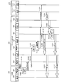
- FIG. 11 is a sequence diagram illustrating an example of bearer duplication operation.
- the communication system 200 operates as the bearer duplication operation, for example, in the steps illustrated in FIG.
- the radio wave condition monitoring unit 621 of the macro cell base station 220 receives the measurement result of the radio wave condition transmitted from the mobile device 201 (step S1101).
- Step S1101 corresponds to, for example, step S1012 shown in FIG. 10A and step S1023 shown in FIG. 10B.
- the radio wave status monitoring unit 621 notifies the threshold value management unit 622 of the radio wave status indicated by the measurement result received in step S1101 (step S1102).
- the threshold value management unit 622 determines the threshold value of the radio wave status (for example, received radio wave intensity) notified in step S1102 (step S1103). In the example shown in FIG. 11, it is assumed that the radio wave condition is less than the first threshold value. Next, the threshold value management unit 622 outputs a determination result indicating that the radio wave condition is less than the first threshold value to the bearer management unit 623 (step S1104).
- the bearer management unit 623 transmits a bearer information request for requesting bearer information regarding the mobile device 201 to the small cell base station 230 (step S1105).
- the bearer management unit 631 of the small cell base station 230 transmits bearer information related to the mobile device 201 to the macro cell base station 220 (step S1106).
- the bearer information is, for example, information indicating QoS (Quality of Service) such as QCI (QoS Class Identifier), PDCP sequence number, lower layer RLC (Radio Link Control) sequence number, and the like.
- QCI Quality of Service
- PDCP Packet Control Protocol
- RLC Radio Link Control
- the bearer management unit 623 of the macro cell base station 220 performs bearer setting of the mobile device 201 based on the bearer information transmitted in step S1106 (step S1107). Thereby, the bearer of the mobile device 201 set in the small cell base station 230 is copied to the macro cell base station 220.
- the data transmission unit 612 of the core network 210 transmits data for the mobile device 201 to the small cell base station 230 (step S1201).
- the data receiving unit 632 of the small cell base station 230 outputs the received data in step S1201 to the data duplicating unit 633 (step S1202).
- the data replication unit 633 performs data replication of the received data output from the data reception unit 632 (step S1203).
- the data replication unit 633 outputs the reception data (original data) output from the data reception unit 632 to the data transmission unit 634 (step S1204).
- the data transmission unit 634 transmits the original data output in step S1204 to the mobile device 201 (step S1205).
- the original data transmitted in step S1205 is received by the data receiving unit 602 of the mobile device 201.
- the buffer 625 deletes the buffering data based on the data deletion request output in step S1310 (step S1311).
- the macrocell base station 220 buffers the data transferred from the small cell base station 230 until bearer switching.
- the macro cell base station 220 sequentially deletes buffering data during a period in which the radio wave condition is equal to or greater than the second threshold.
- the buffering data during a period when the radio wave condition is equal to or greater than the second threshold is likely to reach the mobile device 201 from the small cell base station 230. Can be planned. Further, the amount of use of the buffer 625 can be reduced.
- the data management unit 624 outputs a data transmission request for requesting transmission of buffering data to the buffer 625 (step S1407).
- the buffer 625 outputs the buffering data to the data transmission unit 627 (step S1408).
- the data transmission unit 627 transmits the data (buffering data) output in step S1408 to the mobile device 201 (step S1409).
- the data transmitted in step S1409 is received by the data receiving unit 602 of the mobile device 201.
- the data replication unit 633 stops data replication and data transfer (step S1512).
- the data replication unit 633 stops the data replication in step S1203 shown in FIG. 12 and the data transfer in step S1206 shown in FIG.
- step S1602 when the received radio wave intensity is less than the first threshold (step S1602: Yes), the macro cell base station 220 copies the bearer of the mobile device 201 set in the small cell base station 230 to the own station. (Step S1603). Further, the macro cell base station 220 starts buffering of data transferred from the small cell base station 230 (step S1604).
- the macro cell base station 220 executes, for example, each step shown in FIG. 17 after step S1904 shown in FIG.
- the cell switching can be performed by switching the bearer to be used to the duplicate bearer. For this reason, cell switching can be performed in a short time, and throughput reduction during cell switching can be suppressed.
- Terminal device 110 1st base station apparatus 111 1st cell 120 2nd base station apparatus 121 2nd cell 122 Acquisition part 123 Control part 200 Communication system 201,800 Mobile device 210 Core network 211 Host apparatus 220 Macrocell base station 221 Macrocell 230 Small cell base station 231 Small cell 241 242 S1 interface 243 X2 interface 251 252 RRC 330 Protocol stack 501 to 503 Radio wave status change 601 Radio wave status measurement unit 602, 626, 632 Data reception unit 611, 623, 631 Bearer management unit 612, 627, 634 Data transmission unit 621 Radio wave status monitoring unit 622 Threshold management unit 624 Data management Section 625 Buffer 633 Data replication section 700 Base station 701, 801 Antenna 702, 802 Amplifier 703, 803 Processor 704, 804 Memory 705 Transmission path interface 706 Network 900 Radio wave condition monitoring table
Abstract
A terminal apparatus (101) connects to a first cell (111) and a second cell (121) and performs communications by use of a first bearer that is set in the first cell (111). When the radio quality of the first cell (111) in the terminal apparatus (101) becomes less than a first predetermined value, a base station apparatus (120) sets, in the second cell (121), a second bearer obtained by duplicating the first bearer. When the radio quality of the first cell (111) in the terminal apparatus (101) becomes less than a second predetermined value that is lower than the first predetermined value, the base station apparatus (120) switches the communication bearer of the terminal apparatus (101) from the first bearer to the second bearer.
Description
本発明は、基地局装置およびシステムに関する。
The present invention relates to a base station apparatus and system.
従来、LTE(Long Term Evolution)などの通信システムが知られている。また、移動機のハンドオーバ時に予め切替先のベアラを設定する技術が知られている(たとえば、下記特許文献1参照。)。また、移動機がアイドル状態からアクティブ状態に遷移する際に、アクセスするセルを事前に選択する技術が知られている(たとえば、下記特許文献2参照。)。
Conventionally, communication systems such as LTE (Long Term Evolution) are known. In addition, a technique for setting a switching bearer in advance at the time of handover of a mobile device is known (for example, see Patent Document 1 below). In addition, a technique is known in which a cell to be accessed is selected in advance when a mobile device transitions from an idle state to an active state (see, for example, Patent Document 2 below).
しかしながら、上述した従来技術では、たとえばスモールセルからマクロセルへのハンドオーバなどのセル切替に時間がかかり、セル切替時のスループットの低下を抑えることができないという問題がある。
However, the above-described conventional technique has a problem that it takes time to switch cells such as a handover from a small cell to a macro cell, and the reduction in throughput at the time of cell switching cannot be suppressed.
1つの側面では、本発明は、セル切替時のスループットの低下を抑えることができる基地局装置およびシステムを提供することを目的とする。
In one aspect, an object of the present invention is to provide a base station apparatus and system that can suppress a decrease in throughput during cell switching.
上述した課題を解決し、目的を達成するため、本発明の一側面によれば、第1セルおよび第2セルに接続し前記第1セルに設定された第1ベアラによって通信を行う端末装置における測定結果を示す測定報告が第1条件を満たすと前記第1ベアラを複製した第2ベアラを前記第2セルに設定し、前記測定報告が前記第1条件とは異なる第2条件を満たすと前記端末装置の通信のベアラを前記第1ベアラから前記第2ベアラに切り替える基地局装置およびシステムが提案される。
In order to solve the above-described problems and achieve the object, according to one aspect of the present invention, in a terminal apparatus that is connected to a first cell and a second cell and performs communication using a first bearer set in the first cell. When the measurement report indicating the measurement result satisfies the first condition, the second bearer copied from the first bearer is set in the second cell, and when the measurement report satisfies the second condition different from the first condition, A base station apparatus and system for switching a communication bearer of a terminal apparatus from the first bearer to the second bearer are proposed.
本発明の一側面によれば、セル切替時のスループットの低下を抑えることができるという効果を奏する。
According to one aspect of the present invention, it is possible to suppress a decrease in throughput during cell switching.
以下に図面を参照して、本発明にかかる基地局装置およびシステムの実施の形態を詳細に説明する。
Embodiments of a base station apparatus and system according to the present invention will be described below in detail with reference to the drawings.
(実施の形態1)
(実施の形態1にかかるシステム)
図1Aは、実施の形態1にかかるシステムの一例を示す図である。図1Bは、図1Aに示したシステムにおける信号の流れの一例を示す図である。図1A,図1Bに示すように、実施の形態1にかかるシステム100は、第1基地局装置110と、第2基地局装置120と、端末装置101と、を含む。 (Embodiment 1)
(System according to the first embodiment)
FIG. 1A is a diagram illustrating an example of a system according to the first embodiment. 1B is a diagram illustrating an example of a signal flow in the system illustrated in FIG. 1A. As illustrated in FIG. 1A and FIG. 1B, thesystem 100 according to the first embodiment includes a first base station apparatus 110, a second base station apparatus 120, and a terminal apparatus 101.
(実施の形態1にかかるシステム)
図1Aは、実施の形態1にかかるシステムの一例を示す図である。図1Bは、図1Aに示したシステムにおける信号の流れの一例を示す図である。図1A,図1Bに示すように、実施の形態1にかかるシステム100は、第1基地局装置110と、第2基地局装置120と、端末装置101と、を含む。 (Embodiment 1)
(System according to the first embodiment)
FIG. 1A is a diagram illustrating an example of a system according to the first embodiment. 1B is a diagram illustrating an example of a signal flow in the system illustrated in FIG. 1A. As illustrated in FIG. 1A and FIG. 1B, the
第1セル111は、第1基地局装置110のセルである。第2セル121は、第2基地局装置120のセルである。第1セル111は、少なくとも一部が第2セル121と重複するセルである。たとえば、第1セル111は第2セル121に包含されていてもよい。
The first cell 111 is a cell of the first base station apparatus 110. The second cell 121 is a cell of the second base station device 120. The first cell 111 is a cell that at least partially overlaps the second cell 121. For example, the first cell 111 may be included in the second cell 121.
端末装置101は、第1セル111と第2セル121との重複部分に位置しており、第1セル111および第2セル121と同時に接続している。また、端末装置101は、第1セル111に設定された第1ベアラによって通信を行っているとする。なお、このとき、端末装置101は、同時に第2セル121に設定された他のベアラによる通信を行っていてもよい。
The terminal device 101 is located in an overlapping portion between the first cell 111 and the second cell 121 and is connected simultaneously with the first cell 111 and the second cell 121. In addition, it is assumed that the terminal apparatus 101 performs communication using the first bearer set in the first cell 111. At this time, the terminal apparatus 101 may perform communication using another bearer set in the second cell 121 at the same time.
第2基地局装置120は、たとえば第1セル111と第2セル121とを管理する基地局装置である。第2基地局装置120は、取得部122と、制御部123と、を備える。
The second base station apparatus 120 is a base station apparatus that manages the first cell 111 and the second cell 121, for example. The second base station apparatus 120 includes an acquisition unit 122 and a control unit 123.
取得部122は、端末装置101における測定結果を示す測定報告を取得する。たとえば、取得部122は、第1セル111における端末装置101の無線品質に関する無線品質情報を取得する。無線品質に関する無線品質情報は、たとえば無線品質を示す情報である。無線品質は、たとえばRSSI(Received Signal Strength Indicator:受信信号強度)などの受信電波強度である。取得部122は、取得した無線品質情報を制御部123へ出力する。
The acquisition unit 122 acquires a measurement report indicating a measurement result in the terminal device 101. For example, the acquisition unit 122 acquires wireless quality information regarding the wireless quality of the terminal device 101 in the first cell 111. The radio quality information regarding the radio quality is information indicating the radio quality, for example. The radio quality is, for example, received radio wave strength such as RSSI (Received Signal Strength Indicator). The acquisition unit 122 outputs the acquired wireless quality information to the control unit 123.
たとえば、取得部122は、図1A,図1Bに示す例のように端末装置101から無線送信される無線品質情報を直接受信する。または、取得部122は、端末装置101からの無線品質情報を、たとえば第1基地局装置110を介して取得してもよい。
For example, the acquisition unit 122 directly receives wireless quality information wirelessly transmitted from the terminal device 101 as in the example illustrated in FIGS. 1A and 1B. Or the acquisition part 122 may acquire the radio | wireless quality information from the terminal device 101 via the 1st base station apparatus 110, for example.
制御部123は、取得部122から出力された無線品質情報に基づいて、端末装置101の通信に用いるベアラの切替を行う。たとえば、制御部123は、端末装置101における第1基地局装置110の無線品質が第1所定値を下回ると(第1条件を満たすと)、第1セル111に設定された端末装置101の第1ベアラを複製した第2ベアラを第2セル121に設定する。
The control unit 123 switches bearers used for communication of the terminal device 101 based on the wireless quality information output from the acquisition unit 122. For example, when the radio quality of the first base station device 110 in the terminal device 101 falls below the first predetermined value (if the first condition is satisfied), the control unit 123 sets the first terminal device 101 set in the first cell 111. A second bearer that duplicates one bearer is set in the second cell 121.
また、制御部123は、端末装置101における第1基地局装置110の無線品質が第2所定値を下回ると(第2条件を満たすと)、端末装置101の通信のベアラを第1ベアラから第2ベアラに切り替える。これにより、端末装置101の通信に使用されるセルが第1セル111から第2セル121へ切り替わる。第2所定値は、第1所定値より低い値である。
Further, when the radio quality of the first base station device 110 in the terminal device 101 falls below the second predetermined value (when the second condition is satisfied), the control unit 123 changes the communication bearer of the terminal device 101 from the first bearer. Switch to 2 bearers. Thereby, the cell used for the communication of the terminal device 101 is switched from the first cell 111 to the second cell 121. The second predetermined value is a value lower than the first predetermined value.
このように、実施の形態1によれば、端末装置101における第1セル111の無線品質の劣化を検知した場合に、第1セル111で確立している端末装置101のベアラを第2セル121に複製することができる。そして、端末装置101における第1セル111の無線品質のさらなる劣化を検知した場合に、端末装置101の通信に使用するベアラを複製ベアラに切り替えることができる。
As described above, according to the first embodiment, when the deterioration of the radio quality of the first cell 111 in the terminal device 101 is detected, the bearer of the terminal device 101 established in the first cell 111 is changed to the second cell 121. Can be duplicated. And when the further deterioration of the radio | wireless quality of the 1st cell 111 in the terminal device 101 is detected, the bearer used for the communication of the terminal device 101 can be switched to a duplication bearer.
これにより、たとえばセル切替時にベアラの移動などを行わなくても、使用するベアラを複製ベアラに切り替えることでセル切替を行うことができる。このため、短時間でのセル切替が可能になり、セル切替時のスループット低下を抑えることができる。
Thus, for example, cell switching can be performed by switching the bearer to be used to the duplicate bearer without moving the bearer at the time of cell switching. For this reason, cell switching can be performed in a short time, and throughput reduction during cell switching can be suppressed.
なお、第2基地局装置120が取得部122および制御部123を備える構成について説明したが、第1基地局装置110が取得部122および制御部123を備える構成としてもよい。
In addition, although the 2nd base station apparatus 120 demonstrated the structure provided with the acquisition part 122 and the control part 123, it is good also as a structure with which the 1st base station apparatus 110 is provided with the acquisition part 122 and the control part 123.
また、無線品質情報が無線品質を示す情報である場合について説明したが、無線品質情報は、無線品質に関する無線品質情報が第1所定値以下であることを示す情報や、無線品質に関する無線品質情報が第2所定値以下であることを示す情報などであってもよい。
Moreover, although the case where the wireless quality information is information indicating the wireless quality has been described, the wireless quality information includes information indicating that the wireless quality information related to the wireless quality is equal to or less than a first predetermined value, and wireless quality information related to the wireless quality. May be information indicating that is less than or equal to the second predetermined value.
<バッファリング>
制御部123は、端末装置101における第1セル111の無線品質が第1所定値を下回り、複製ベアラを第2セル121に設定した場合に、以下のバッファリングを制御してもよい。すなわち、制御部123は、第1セル111が第1ベアラで端末装置101へ送信するデータの複製データを第1基地局装置110から第2基地局装置120へ送信させ、第2基地局装置120に複製データをバッファリングさせる制御を行ってもよい。 <Buffering>
Thecontrol unit 123 may control the following buffering when the radio quality of the first cell 111 in the terminal device 101 is lower than the first predetermined value and the duplicate bearer is set in the second cell 121. That is, the control unit 123 causes the first base station device 110 to transmit the duplicate data of the data that the first cell 111 transmits to the terminal device 101 by the first bearer to the second base station device 120, and the second base station device 120. Control may be performed to buffer the replicated data.
制御部123は、端末装置101における第1セル111の無線品質が第1所定値を下回り、複製ベアラを第2セル121に設定した場合に、以下のバッファリングを制御してもよい。すなわち、制御部123は、第1セル111が第1ベアラで端末装置101へ送信するデータの複製データを第1基地局装置110から第2基地局装置120へ送信させ、第2基地局装置120に複製データをバッファリングさせる制御を行ってもよい。 <Buffering>
The
この場合に、制御部123は、端末装置101における第1セル111の無線品質が第2所定値を下回り、端末装置101の通信に使用するベアラを複製ベアラに切り替えると、以下の制御を行う。すなわち、制御部123は、第2基地局装置120にバッファリングさせておいた複製データを第2ベアラで端末装置101へ送信させる。これにより、ベアラ切替時に短時間で第2ベアラでのデータ送信を開始することができる。このため、セル切替時のスループット低下を抑えることができる。
In this case, the control unit 123 performs the following control when the radio quality of the first cell 111 in the terminal device 101 falls below the second predetermined value and the bearer used for communication of the terminal device 101 is switched to the duplicate bearer. That is, the control unit 123 causes the second base station apparatus 120 to transmit the duplicated data that has been buffered to the terminal apparatus 101 using the second bearer. Thereby, the data transmission by a 2nd bearer can be started in a short time at the time of bearer switching. For this reason, it is possible to suppress a decrease in throughput during cell switching.
また、この場合に、制御部123は、端末装置101の通信に使用するベアラを複製ベアラに切り替えた後に、第2基地局装置120に対して、他の通信装置から受信した端末装置101へのデータをバッファリングしながら、複製データの送信を行わせてもよい。他の通信装置は、たとえば第2基地局装置120の上位装置である。
Also, in this case, the control unit 123 switches the bearer used for communication of the terminal device 101 to the duplicate bearer, and then sends the second base station device 120 to the terminal device 101 received from another communication device. The replica data may be transmitted while buffering the data. The other communication device is, for example, a host device of the second base station device 120.
そして、制御部123は、第2基地局装置120に対して、複製データの送信が完了した後に、他の通信装置から受信してバッファリングしておいた端末装置101へのデータの第2ベアラでの送信を開始させる。これにより、端末装置101における第1セル111の無線品質が第2所定値を下回るまでのデータ(複製データ)と、端末装置101における第1セル111の無線品質が第2所定値を下回ってからのデータと、の順序保証を行うことができる。
The control unit 123 then transmits the second bearer of the data to the terminal apparatus 101 received and buffered from the other communication apparatus after the transmission of the duplicate data to the second base station apparatus 120 is completed. Start sending with. Thereby, data until the wireless quality of the first cell 111 in the terminal device 101 falls below the second predetermined value (duplicated data) and after the wireless quality of the first cell 111 in the terminal device 101 falls below the second predetermined value. The order of the data can be guaranteed.
<送信対象の複製データ>
制御部123は、第2基地局装置120がベアラ切替後に送信する複製データを、バッファリングした複製データのうちの、端末装置101における第1セル111の無線品質が第2所定値を下回っていなかった時点までの複製データとしてもよい。これにより、端末装置101が第1セル111から正常に受信できた可能性が高いデータを第2セル121から再度送信することを抑制することができる。 <Replication data to be sent>
Thecontrol unit 123 is configured such that the radio quality of the first cell 111 in the terminal device 101 is not lower than the second predetermined value among the duplicated data buffered from the duplicated data transmitted by the second base station device 120 after bearer switching. It may be replicated data up to the point in time. Thereby, it is possible to prevent the terminal device 101 from transmitting again from the second cell 121 data that is highly likely to be normally received from the first cell 111.
制御部123は、第2基地局装置120がベアラ切替後に送信する複製データを、バッファリングした複製データのうちの、端末装置101における第1セル111の無線品質が第2所定値を下回っていなかった時点までの複製データとしてもよい。これにより、端末装置101が第1セル111から正常に受信できた可能性が高いデータを第2セル121から再度送信することを抑制することができる。 <Replication data to be sent>
The
この場合に、制御部123は、端末装置101における第1セル111の無線品質が第1所定値を下回り第2所定値を下回っていない場合は、第2基地局装置120がバッファリングしている複製データを順次削除させる制御を行ってもよい。これにより、第2基地局装置120におけるバッファリングのためのメモリの使用量を削減することができる。
In this case, when the wireless quality of the first cell 111 in the terminal device 101 is lower than the first predetermined value and not lower than the second predetermined value, the control unit 123 buffers the second base station device 120. You may perform control to delete replication data sequentially. Thereby, the amount of memory used for buffering in the second base station apparatus 120 can be reduced.
<無線品質の改善時の処理>
また、制御部123は、端末装置101における第1セル111の無線品質が第1所定値を下回った後に第3所定値を上回った場合に、第2セル121に設定した第2ベアラを削除してもよい。第3所定値は、第1所定値以上の値である。これにより、端末装置101における第1セル111の無線品質が改善した場合に第2セル121における無線リソースを解放し、無線リソースの使用効率を向上させることができる。 <Process when improving wireless quality>
Moreover, thecontrol part 123 deletes the 2nd bearer set to the 2nd cell 121, when the radio quality of the 1st cell 111 in the terminal device 101 exceeds 3rd predetermined value after falling below 1st predetermined value. May be. The third predetermined value is a value greater than or equal to the first predetermined value. Thereby, when the radio quality of the first cell 111 in the terminal device 101 is improved, the radio resource in the second cell 121 can be released, and the use efficiency of the radio resource can be improved.
また、制御部123は、端末装置101における第1セル111の無線品質が第1所定値を下回った後に第3所定値を上回った場合に、第2セル121に設定した第2ベアラを削除してもよい。第3所定値は、第1所定値以上の値である。これにより、端末装置101における第1セル111の無線品質が改善した場合に第2セル121における無線リソースを解放し、無線リソースの使用効率を向上させることができる。 <Process when improving wireless quality>
Moreover, the
また、制御部123は、端末装置101における第1セル111の無線品質が第1所定値を下回った後に第3所定値を上回った場合に、第1基地局装置110から第2基地局装置120への複製データの送信を停止させる制御を行ってもよい。これにより、端末装置101における第1セル111の無線品質が改善した場合に第1基地局装置110と第2基地局装置120との間のトラヒックを低減することができる。
Further, the control unit 123, when the radio quality of the first cell 111 in the terminal device 101 exceeds the first predetermined value and then exceeds the third predetermined value, the first base station device 110 to the second base station device 120. You may perform control which stops transmission of the replication data to. Thereby, when the radio quality of the 1st cell 111 in the terminal device 101 improves, the traffic between the 1st base station apparatus 110 and the 2nd base station apparatus 120 can be reduced.
<変形例>
取得部122は、端末装置101の移動速度と、端末装置101における第1セル111の無線品質と、に関する情報を取得してもよい。この情報は、たとえば端末装置101の移動速度および無線品質を示す情報である。この場合に、制御部123は、端末装置101の移動速度が所定速度を上回ると、第1セル111に設定された端末装置101の第1ベアラを複製した第2ベアラを第2セル121に設定する。 <Modification>
Theacquisition unit 122 may acquire information related to the moving speed of the terminal device 101 and the wireless quality of the first cell 111 in the terminal device 101. This information is information indicating the moving speed and radio quality of the terminal device 101, for example. In this case, when the moving speed of the terminal device 101 exceeds a predetermined speed, the control unit 123 sets the second bearer, which is a duplicate of the first bearer of the terminal device 101 set in the first cell 111, in the second cell 121. To do.
取得部122は、端末装置101の移動速度と、端末装置101における第1セル111の無線品質と、に関する情報を取得してもよい。この情報は、たとえば端末装置101の移動速度および無線品質を示す情報である。この場合に、制御部123は、端末装置101の移動速度が所定速度を上回ると、第1セル111に設定された端末装置101の第1ベアラを複製した第2ベアラを第2セル121に設定する。 <Modification>
The
また、制御部123は、端末装置101における第1基地局装置110の無線品質が所定値(たとえば上述した第2所定値)を下回ると、端末装置101の通信のベアラを第1ベアラから第2ベアラに切り替える。これにより、端末装置101の通信に使用されるセルが第1セル111から第2セル121へ切り替わる。第2所定値は、第1所定値より低い値である。
Further, when the radio quality of the first base station device 110 in the terminal device 101 falls below a predetermined value (for example, the second predetermined value described above), the control unit 123 changes the communication bearer of the terminal device 101 from the first bearer to the second bearer. Switch to bearer. Thereby, the cell used for the communication of the terminal device 101 is switched from the first cell 111 to the second cell 121. The second predetermined value is a value lower than the first predetermined value.
このように、実施の形態1において、端末装置101の移動速度の増加を検知した場合に、第1セル111で確立している端末装置101のベアラを第2セル121に複製するようにしてもよい。そして、端末装置101における第1セル111の無線品質の劣化を検知した場合に、端末装置101の通信に使用するベアラを複製ベアラに切り替える。
As described above, in the first embodiment, when an increase in the moving speed of the terminal device 101 is detected, the bearer of the terminal device 101 established in the first cell 111 may be copied to the second cell 121. Good. And when the deterioration of the wireless quality of the 1st cell 111 in the terminal device 101 is detected, the bearer used for the communication of the terminal device 101 is switched to a replication bearer.
これにより、端末装置101の移動によって端末装置101における第1セル111の無線品質が劣化する前に、端末装置101のベアラを第2セル121に複製しておくことができる。したがって、たとえばセル切替時にベアラの移動などを行わなくても、使用するベアラを複製ベアラに切り替えることでセル切替を行うことができる。このため、短時間でのセル切替が可能になり、セル切替時のスループット低下を抑えることができる。
Thus, the bearer of the terminal device 101 can be copied to the second cell 121 before the wireless quality of the first cell 111 in the terminal device 101 deteriorates due to the movement of the terminal device 101. Therefore, for example, cell switching can be performed by switching a bearer to be used to a duplicate bearer without performing bearer movement at the time of cell switching. For this reason, cell switching can be performed in a short time, and throughput reduction during cell switching can be suppressed.
また、取得部122が取得する情報が移動速度を示す情報である場合について説明したが、取得部122が取得する情報は、移動速度が所定速度を上回ったことを示す情報などであってもよい。
Moreover, although the case where the information acquired by the acquisition unit 122 is information indicating the movement speed has been described, the information acquired by the acquisition unit 122 may be information indicating that the movement speed exceeds a predetermined speed. .
また、制御部123は、端末装置101の移動速度が所定速度を上回り、かつ無線品質が第1所定値を下回った場合に、第1セル111に設定された端末装置101の第1ベアラを複製した第2ベアラを第2セル121に設定するようにしてもよい。
In addition, the control unit 123 duplicates the first bearer of the terminal device 101 set in the first cell 111 when the moving speed of the terminal device 101 exceeds the predetermined speed and the wireless quality falls below the first predetermined value. The second bearer may be set in the second cell 121.
(実施の形態2)
(実施の形態2にかかる通信システム)
図2Aは、実施の形態2にかかる通信システムの一例を示す図である。図2Aに示すように、実施の形態2にかかる通信システム200は、コアネットワーク210と、マクロセル基地局220と、スモールセル基地局230と、移動機201と、を含む。通信システム200は、たとえば3GPP(3rd Generation Partnership Project)で規定されるLTEなどの通信システムである。 (Embodiment 2)
(Communication system according to Embodiment 2)
FIG. 2A is a diagram illustrating an example of a communication system according to the second embodiment. As illustrated in FIG. 2A, thecommunication system 200 according to the second embodiment includes a core network 210, a macro cell base station 220, a small cell base station 230, and a mobile device 201. The communication system 200 is a communication system such as LTE defined by 3GPP (3rd Generation Partnership Project), for example.
(実施の形態2にかかる通信システム)
図2Aは、実施の形態2にかかる通信システムの一例を示す図である。図2Aに示すように、実施の形態2にかかる通信システム200は、コアネットワーク210と、マクロセル基地局220と、スモールセル基地局230と、移動機201と、を含む。通信システム200は、たとえば3GPP(3rd Generation Partnership Project)で規定されるLTEなどの通信システムである。 (Embodiment 2)
(Communication system according to Embodiment 2)
FIG. 2A is a diagram illustrating an example of a communication system according to the second embodiment. As illustrated in FIG. 2A, the
図1A,図1Bに示したシステム100は、たとえば通信システム200により実現することができる。この場合に、図1A,図1Bに示した第1基地局装置110は、たとえばマクロセル基地局220により実現することができる。また、図1A,図1Bに示した第2基地局装置120は、たとえばスモールセル基地局230により実現することができる。また、図1A,図1Bに示した端末装置101は、たとえば移動機201により実現することができる。
1A and 1B can be realized by the communication system 200, for example. In this case, the first base station apparatus 110 shown in FIGS. 1A and 1B can be realized by the macro cell base station 220, for example. Moreover, the 2nd base station apparatus 120 shown to FIG. 1A and FIG. 1B is realizable by the small cell base station 230, for example. 1A and 1B can be realized by the mobile device 201, for example.
上位装置211は、コアネットワーク210に含まれる通信装置であって、マクロセル基地局220およびスモールセル基地局230の上位装置である。たとえば、上位装置211は、SGW(Serving Gateway)などである。
The host device 211 is a communication device included in the core network 210 and is a host device of the macro cell base station 220 and the small cell base station 230. For example, the host device 211 is a SGW (Serving Gateway) or the like.
マクロセル221は、マクロセル基地局220が形成するセルである。マクロセル基地局220は、たとえばeNB(evolved Node B)である。スモールセル231は、スモールセル基地局230が形成するセルである。スモールセル231は、たとえば、フェムトセル、ピコセル、ナノセルなどの、マクロセル221と比べて範囲が小さいセルである。
The macro cell 221 is a cell formed by the macro cell base station 220. The macro cell base station 220 is, for example, an eNB (evolved Node B). The small cell 231 is a cell formed by the small cell base station 230. The small cell 231 is a cell having a smaller range than the macro cell 221 such as a femto cell, a pico cell, or a nano cell.
マクロセル基地局220およびスモールセル基地局230は、それぞれS1インターフェース241,242によってコアネットワーク210の上位装置211と接続されている。また、マクロセル基地局220およびスモールセル基地局230は、X2インターフェース243によって互いに接続されている。
The macro cell base station 220 and the small cell base station 230 are connected to the host device 211 of the core network 210 by S1 interfaces 241 and 242 respectively. In addition, the macro cell base station 220 and the small cell base station 230 are connected to each other by the X2 interface 243.
移動機201は、たとえばUE(User Equipment:ユーザ端末)である。移動機201は、マクロセル基地局220およびスモールセル基地局230に接続可能である。また、移動機201は、マクロセル基地局220およびスモールセル基地局230と同時に通信を行い、マクロセル基地局220およびスモールセル基地局230からそれぞれ別のデータ(たとえばU-Planeデータ)を受信可能である。
The mobile device 201 is, for example, a UE (User Equipment: user terminal). The mobile device 201 can be connected to the macro cell base station 220 and the small cell base station 230. Further, the mobile device 201 can communicate with the macro cell base station 220 and the small cell base station 230 at the same time, and can receive different data (for example, U-Plane data) from the macro cell base station 220 and the small cell base station 230, respectively. .
この場合に、コアネットワーク210の上位装置211は、それぞれ別のデータをマクロセル基地局220およびスモールセル基地局230へ送信する。たとえば、移動機201は、それぞれ異なる周波数によってマクロセル基地局220およびスモールセル基地局230と同時に通信を行う。
In this case, the host device 211 of the core network 210 transmits different data to the macro cell base station 220 and the small cell base station 230, respectively. For example, the mobile device 201 performs communication simultaneously with the macro cell base station 220 and the small cell base station 230 at different frequencies.
また、上位装置211は、移動機201へ送信するデータの転送経路を、データの種類に応じて選択してもよい。たとえば、上位装置211は、高スループットよりも確実な通信を要する音声通信などのデータについては、マクロセル基地局220を経由して移動機201へ送信する。音声通信は、たとえばVoIP(Voice over IP)やVoLTE(Voice over LTE)などである。また、上位装置211は、高スループットを要するストリーミングなどの通信についてはスモールセル基地局230を経由して移動機201へ送信する。
Further, the higher-level device 211 may select a transfer path for data to be transmitted to the mobile device 201 according to the type of data. For example, the host device 211 transmits data such as voice communication that requires more reliable communication than high throughput to the mobile device 201 via the macro cell base station 220. Voice communication is, for example, VoIP (Voice over IP), VoLTE (Voice over LTE), or the like. Further, the host apparatus 211 transmits communication such as streaming that requires high throughput to the mobile device 201 via the small cell base station 230.
(プロトコルアーキテクチャ)
図2Bは、プロトコルアーキテクチャの一例を示す図である。図2Bに示すRRC251(Radio Resource Control:無線リソース制御)は、マクロセル基地局220におけるRRCの制御部である。RRC252は、移動機201におけるRRCの制御部である。 (Protocol architecture)
FIG. 2B is a diagram illustrating an example of a protocol architecture. RRC 251 (Radio Resource Control) shown in FIG. 2B is an RRC control unit in macrocell base station 220. The RRC 252 is an RRC control unit in the mobile device 201.
図2Bは、プロトコルアーキテクチャの一例を示す図である。図2Bに示すRRC251(Radio Resource Control:無線リソース制御)は、マクロセル基地局220におけるRRCの制御部である。RRC252は、移動機201におけるRRCの制御部である。 (Protocol architecture)
FIG. 2B is a diagram illustrating an example of a protocol architecture. RRC 251 (Radio Resource Control) shown in FIG. 2B is an RRC control unit in macro
マクロセル基地局220と移動機201との間のRRCは、それぞれRRC251,252によって終端される。また、スモールセル基地局230を経由する移動機201の通信のRRCについてもRRC251,252によって終端される。このように、マクロセル基地局220のRRC251においては、マクロセル221のU-Plane経路と、スモールセル231のU-Plane経路と、の両方の管理が行われる。
RRC between the macro cell base station 220 and the mobile device 201 is terminated by RRC 251 and 252 respectively. Also, RRC 251 and 252 terminate the RRC for communication of the mobile device 201 via the small cell base station 230. Thus, in the RRC 251 of the macro cell base station 220, both the U-Plane path of the macro cell 221 and the U-Plane path of the small cell 231 are managed.
(ベアラ切替)
図3Aおよび図3Bは、ベアラ切替の一例を示す図である。図3A,図3Bに示すように、たとえば、マクロセル基地局220と移動機201との間には、セル#1を用いたベアラ#1と、セル#2を用いたベアラ#2と、が設定される。そして、マクロセル基地局220および移動機201は、たとえば、図3Aに示すようにベアラ#1を用いて通信を行う状態から、図3Bに示すようにベアラ#2を用いて通信を行う状態へ切り替えるベアラ切替を行う。 (Bearer switching)
3A and 3B are diagrams illustrating an example of bearer switching. As shown in FIGS. 3A and 3B, for example, abearer # 1 using cell # 1 and a bearer # 2 using cell # 2 are set between the macro cell base station 220 and the mobile device 201. Is done. Then, for example, the macro cell base station 220 and the mobile device 201 switch from a state where communication is performed using the bearer # 1 as illustrated in FIG. 3A to a state where communication is performed using the bearer # 2 as illustrated in FIG. 3B. Switch bearer.
図3Aおよび図3Bは、ベアラ切替の一例を示す図である。図3A,図3Bに示すように、たとえば、マクロセル基地局220と移動機201との間には、セル#1を用いたベアラ#1と、セル#2を用いたベアラ#2と、が設定される。そして、マクロセル基地局220および移動機201は、たとえば、図3Aに示すようにベアラ#1を用いて通信を行う状態から、図3Bに示すようにベアラ#2を用いて通信を行う状態へ切り替えるベアラ切替を行う。 (Bearer switching)
3A and 3B are diagrams illustrating an example of bearer switching. As shown in FIGS. 3A and 3B, for example, a
このように、移動機201に対して複数のベアラを設定し、セル切替時に、使用するベアラを切り替えることで通信を継続させることができる。これにより、たとえばハンドオーバと比べて短時間でのセル切替が可能になる。
Thus, communication can be continued by setting a plurality of bearers for the mobile device 201 and switching the bearers to be used at the time of cell switching. As a result, for example, cell switching can be performed in a shorter time than handover.
実施の形態2においては、スモールセル基地局230を経由する移動機201のベアラをマクロセル基地局220に複製することで複数のベアラを設定し、使用するベアラをスモールセル基地局230のベアラからマクロセル基地局220のベアラへ切り替える。これにより、短時間でのセル切替が可能になる。
In Embodiment 2, a plurality of bearers are set by duplicating the bearer of the mobile device 201 via the small cell base station 230 to the macro cell base station 220, and the bearer to be used is changed from the bearer of the small cell base station 230 to the macro cell. Switch to the bearer of base station 220. Thereby, cell switching in a short time becomes possible.
(U-Planeのプロトコルスタック)
図3Cは、U-Planeのプロトコルスタックの一例を示す図である。図3Cに示すプロトコルスタック330は、たとえばE-UTRAN(Evolved Universal Terrestrial Radio Access Network)におけるU-Planeのプロトコルスタックである。上述したベアラの複製は、たとえばPDCP(Packet Data Convergence Protocol)レイヤによって行うことができる。 (U-Plane protocol stack)
FIG. 3C is a diagram illustrating an example of a U-Plane protocol stack. Aprotocol stack 330 illustrated in FIG. 3C is a U-Plane protocol stack in E-UTRAN (Evolved Universal Terrestrial Radio Access Network), for example. The above-described bearer replication can be performed by, for example, a PDCP (Packet Data Convergence Protocol) layer.
図3Cは、U-Planeのプロトコルスタックの一例を示す図である。図3Cに示すプロトコルスタック330は、たとえばE-UTRAN(Evolved Universal Terrestrial Radio Access Network)におけるU-Planeのプロトコルスタックである。上述したベアラの複製は、たとえばPDCP(Packet Data Convergence Protocol)レイヤによって行うことができる。 (U-Plane protocol stack)
FIG. 3C is a diagram illustrating an example of a U-Plane protocol stack. A
図3Cに示す移動機はたとえば移動機201である。図3Cに示すマクロセル基地局はたとえばマクロセル基地局220である。図3Cに示すSGWはたとえば上位装置211である。図3Cに示すserverは、コアネットワーク210に設けられ移動機201と通信を行うサーバである。
The mobile device shown in FIG. 3C is a mobile device 201, for example. The macro cell base station illustrated in FIG. 3C is, for example, a macro cell base station 220. The SGW illustrated in FIG. 3C is, for example, the host device 211. The server shown in FIG. 3C is a server that is provided in the core network 210 and communicates with the mobile device 201.
(通信システムの動作)
図4は、通信システムの動作の一例を示す図である。図4において、図2Aに示した部分と同様の部分については同一の符号を付して説明を省略する。 (Operation of communication system)
FIG. 4 is a diagram illustrating an example of the operation of the communication system. 4, parts that are the same as the parts shown in FIG. 2A are given the same reference numerals, and descriptions thereof will be omitted.
<マクロセルによるスモールセルの電波状況管理>
マクロセル基地局220は、移動機201から送信される電波状況の測定結果を監視することで、スモールセル基地局230を用いた通信の電波状況を監視する。移動機201は、たとえば位置登録時などに電波状況の測定結果をマクロセル基地局220へ送信する。また、マクロセル基地局220は、定期的に移動機201に対して電波状況の測定要求を行い、移動機201は、測定要求に対して電波状況の測定結果をマクロセル基地局220へ送信する。 <Small cell radio wave status management by macro cell>
Themacrocell base station 220 monitors the radio wave condition of communication using the small cell base station 230 by monitoring the measurement result of the radio wave condition transmitted from the mobile device 201. The mobile device 201 transmits the measurement result of the radio wave condition to the macro cell base station 220 at the time of position registration, for example. Further, the macro cell base station 220 periodically makes a request for measuring the radio wave condition to the mobile device 201, and the mobile machine 201 transmits the measurement result of the radio wave condition to the macro cell base station 220 in response to the measurement request.
マクロセル基地局220は、移動機201から送信される電波状況の測定結果を監視することで、スモールセル基地局230を用いた通信の電波状況を監視する。移動機201は、たとえば位置登録時などに電波状況の測定結果をマクロセル基地局220へ送信する。また、マクロセル基地局220は、定期的に移動機201に対して電波状況の測定要求を行い、移動機201は、測定要求に対して電波状況の測定結果をマクロセル基地局220へ送信する。 <Small cell radio wave status management by macro cell>
The
<マクロセルへのベアラ複製>
移動機201からの電波状況の測定結果が第1閾値(ベアラ設定閾値)を下回っていた場合、マクロセル基地局220は、スモールセル基地局230に移動機201に関するベアラ情報を要求する。そして、マクロセル基地局220は、スモールセル基地局230と同じベアラをマクロセル基地局220に設定する。 <Bearer replication to macro cell>
When the measurement result of the radio wave condition from themobile device 201 is below the first threshold (bearer setting threshold), the macro cell base station 220 requests bearer information regarding the mobile device 201 from the small cell base station 230. Then, the macro cell base station 220 sets the same bearer as that of the small cell base station 230 in the macro cell base station 220.
移動機201からの電波状況の測定結果が第1閾値(ベアラ設定閾値)を下回っていた場合、マクロセル基地局220は、スモールセル基地局230に移動機201に関するベアラ情報を要求する。そして、マクロセル基地局220は、スモールセル基地局230と同じベアラをマクロセル基地局220に設定する。 <Bearer replication to macro cell>
When the measurement result of the radio wave condition from the
<スモールセルからマクロセルへのデータ転送>
スモールセル基地局230は、コアネットワーク210から受信したデータを移動機201およびマクロセル基地局220のそれぞれの送信用に複製する。そして、スモールセル基地局230は、移動機201へのデータ送信と並行して、マクロセル基地局220へのデータ転送を行う。このデータ転送は、たとえばX2インターフェース243を介して行われる。 <Data transfer from small cell to macro cell>
The smallcell base station 230 replicates the data received from the core network 210 for transmission of each of the mobile device 201 and the macro cell base station 220. Then, the small cell base station 230 performs data transfer to the macro cell base station 220 in parallel with data transmission to the mobile device 201. This data transfer is performed via the X2 interface 243, for example.
スモールセル基地局230は、コアネットワーク210から受信したデータを移動機201およびマクロセル基地局220のそれぞれの送信用に複製する。そして、スモールセル基地局230は、移動機201へのデータ送信と並行して、マクロセル基地局220へのデータ転送を行う。このデータ転送は、たとえばX2インターフェース243を介して行われる。 <Data transfer from small cell to macro cell>
The small
<マクロセルでのデータバッファリング>
マクロセル基地局220は、スモールセル基地局230から転送されたデータをベアラ切替までバッファリングする。また、マクロセル基地局220は、定期的に電波状況を監視し、電波状況の測定結果が第2閾値(ベアラ切替閾値)を下回らない場合は不要なバッファリングデータを削除する。 <Data buffering in macro cell>
The macrocell base station 220 buffers the data transferred from the small cell base station 230 until bearer switching. Further, the macro cell base station 220 periodically monitors the radio wave condition, and deletes unnecessary buffering data when the measurement result of the radio wave condition does not fall below the second threshold (bearer switching threshold).
マクロセル基地局220は、スモールセル基地局230から転送されたデータをベアラ切替までバッファリングする。また、マクロセル基地局220は、定期的に電波状況を監視し、電波状況の測定結果が第2閾値(ベアラ切替閾値)を下回らない場合は不要なバッファリングデータを削除する。 <Data buffering in macro cell>
The macro
<ベアラ切替>
マクロセル基地局220は、電波状況の測定結果が第2閾値(ベアラ切替閾値)を下回った場合は、コアネットワーク210にベアラの切替要求を行うことでベアラ切替を行うとともに、バッファリングデータを移動機201へ送信する。このとき、マクロセル基地局220は、スモールセル基地局230から転送されたデータとコアネットワーク210から送信されるデータの順序保証を行いながら移動機201にデータを送信する。すなわち、マクロセル基地局220は、ベアラ切替後、コアネットワーク210から送信されるデータをバッファリングデータの送信完了後に送信する。 <Bearer switching>
When the measurement result of the radio wave condition falls below the second threshold value (bearer switching threshold value), the macrocell base station 220 performs bearer switching by making a bearer switching request to the core network 210 and transmits the buffering data to the mobile device. To 201. At this time, the macro cell base station 220 transmits data to the mobile device 201 while guaranteeing the order of the data transferred from the small cell base station 230 and the data transmitted from the core network 210. That is, the macro cell base station 220 transmits the data transmitted from the core network 210 after the bearer switching, after the transmission of the buffering data is completed.
マクロセル基地局220は、電波状況の測定結果が第2閾値(ベアラ切替閾値)を下回った場合は、コアネットワーク210にベアラの切替要求を行うことでベアラ切替を行うとともに、バッファリングデータを移動機201へ送信する。このとき、マクロセル基地局220は、スモールセル基地局230から転送されたデータとコアネットワーク210から送信されるデータの順序保証を行いながら移動機201にデータを送信する。すなわち、マクロセル基地局220は、ベアラ切替後、コアネットワーク210から送信されるデータをバッファリングデータの送信完了後に送信する。 <Bearer switching>
When the measurement result of the radio wave condition falls below the second threshold value (bearer switching threshold value), the macro
<ベアラ削除>
マクロセル基地局220は、電波状況の測定結果が第3閾値(ベアラ削除閾値)を上回った場合は、マクロセル基地局220に設定していたベアラを削除し、バッファリングデータの削除を行う。また、マクロセル基地局220は、スモールセル基地局230においてデータの複製および転送が開始されていた場合は、スモールセル基地局230に対してこれらの複製および転送の停止を要求する停止要求を行う。ベアラの削除およびバッファリングデータの削除は、たとえば停止要求によって複製および転送後に行われる。 <Delete bearer>
When the measurement result of the radio wave condition exceeds the third threshold (bearer deletion threshold), the macrocell base station 220 deletes the bearer set in the macro cell base station 220 and deletes the buffering data. In addition, when the small cell base station 230 has started copying and transferring data, the macro cell base station 220 requests the small cell base station 230 to stop the copying and transferring. The deletion of the bearer and the deletion of the buffering data are performed after copying and transfer by a stop request, for example.
マクロセル基地局220は、電波状況の測定結果が第3閾値(ベアラ削除閾値)を上回った場合は、マクロセル基地局220に設定していたベアラを削除し、バッファリングデータの削除を行う。また、マクロセル基地局220は、スモールセル基地局230においてデータの複製および転送が開始されていた場合は、スモールセル基地局230に対してこれらの複製および転送の停止を要求する停止要求を行う。ベアラの削除およびバッファリングデータの削除は、たとえば停止要求によって複製および転送後に行われる。 <Delete bearer>
When the measurement result of the radio wave condition exceeds the third threshold (bearer deletion threshold), the macro
これにより、移動機201へのデータ送信を止めなくてもスモールセル基地局230からマクロセル基地局220へのベアラ切替が可能になる。このため、セル切替におけるスループットの低下を抑えることができる。また、無線区間へ同一データを送信しなくてもベアラ切替が可能になるため、無線区間の負荷の軽減を図ることができる。
This enables bearer switching from the small cell base station 230 to the macro cell base station 220 without stopping data transmission to the mobile device 201. For this reason, it is possible to suppress a decrease in throughput in cell switching. In addition, since bearer switching can be performed without transmitting the same data to the wireless section, it is possible to reduce the load on the wireless section.
(各閾値)
図5は、各閾値の一例を示す図である。図5において、縦軸は電波状況を示している。電波状況は、たとえばRSSIなどの受信電波強度である。受信電波強度が高いほど電波状況が良く、受信電波強度が低いほど電波状況が悪い。 (Each threshold)
FIG. 5 is a diagram illustrating an example of each threshold value. In FIG. 5, the vertical axis represents the radio wave condition. The radio wave status is a received radio wave intensity such as RSSI. The higher the received radio wave intensity, the better the radio wave condition, and the lower the received radio wave intensity, the worse the radio wave condition.
図5に示すように、第1閾値、第2閾値および第3閾値は、たとえば第2閾値<第1閾値<第3閾値の関係を有する。ただし、第1閾値=第3閾値としてもよい。第1閾値、第2閾値および第3閾値は、たとえば任意に変更可能なパラメータであり、たとえば通信キャリアにて個別に設定が可能なパラメータとしてもよい。
As shown in FIG. 5, the first threshold value, the second threshold value, and the third threshold value have, for example, a relationship of second threshold value <first threshold value <third threshold value. However, the first threshold value may be equal to the third threshold value. The first threshold value, the second threshold value, and the third threshold value are parameters that can be arbitrarily changed, for example, and may be parameters that can be individually set in a communication carrier, for example.
第1閾値は、スモールセル基地局230の電波状況の劣化を検出し、予めマクロセル基地局220にベアラを設定(複製)するための閾値である。第2閾値は、スモールセル基地局230の電波状況の劣化を検出し、マクロセル基地局220への切替を行うための閾値である。第3閾値は、スモールセル基地局230の電波状況の改善を検出し、マクロセル基地局220に設定したベアラを解放するための閾値である。
The first threshold value is a threshold value for detecting deterioration of the radio wave condition of the small cell base station 230 and setting (duplicating) a bearer in the macro cell base station 220 in advance. The second threshold value is a threshold value for detecting deterioration of the radio wave condition of the small cell base station 230 and switching to the macro cell base station 220. The third threshold value is a threshold value for detecting the improvement of the radio wave condition of the small cell base station 230 and releasing the bearer set in the macro cell base station 220.
電波状況変化501~503は、移動機201から報告される電波状況の変化を示している。たとえば、電波状況変化501のように、電波状況が第1閾値を下回ると、スモールセル基地局230における通信状況が劣化したと判断することができる。この場合は、スモールセル基地局230は、データの複製およびマクロセル基地局220への転送を開始する。これに対して、マクロセル基地局220は、マクロセル基地局220のベアラを自局に複製(無線リソースの確保)し、マクロセル基地局220からの転送データのバッファリングを開始する。
Radio wave status changes 501 to 503 indicate changes in radio wave status reported from the mobile device 201. For example, when the radio wave condition falls below the first threshold as in the radio wave condition change 501, it can be determined that the communication situation in the small cell base station 230 has deteriorated. In this case, the small cell base station 230 starts data replication and transfer to the macro cell base station 220. On the other hand, the macro cell base station 220 copies the bearer of the macro cell base station 220 to the own station (secures radio resources), and starts buffering of transfer data from the macro cell base station 220.
つぎに、電波状況変化502のように、電波状況が第2閾値も下回ると、スモールセル基地局230における通信状況がさらに劣化し、スモールセル基地局230における通信が困難になったと判断することができる。この場合は、マクロセル基地局220は、移動機201のベアラをスモールセル基地局230からマクロセル基地局220に切り替えるベアラ切替を行う。これにより、移動機201へのデータ送信を継続することができる。
Next, when the radio wave condition falls below the second threshold as in the radio wave condition change 502, it is determined that the communication situation in the small cell base station 230 is further deteriorated and communication in the small cell base station 230 becomes difficult. it can. In this case, the macro cell base station 220 performs bearer switching for switching the bearer of the mobile device 201 from the small cell base station 230 to the macro cell base station 220. Thereby, the data transmission to the mobile device 201 can be continued.
また、電波状況変化503のように、電波状況が第3閾値を超えると、スモールセル基地局230における通信状況が改善したと判断することができる。この場合は、マクロセル基地局220は、電波状況変化501において設定したベアラを削除(無線リソースを解放)し、バッファリングデータを削除する。また、スモールセル基地局230は、データの複製および転送を停止し、移動機201へのデータ送信を継続する。
In addition, when the radio wave condition exceeds the third threshold as in the radio wave condition change 503, it can be determined that the communication situation in the small cell base station 230 has improved. In this case, the macro cell base station 220 deletes the bearer set in the radio wave status change 501 (releases radio resources) and deletes buffering data. In addition, the small cell base station 230 stops data replication and transfer, and continues data transmission to the mobile device 201.
(通信システムの各装置の構成)
図6Aは、通信システムの各装置の構成の一例を示す図である。図6Bは、図6Aに示した通信システムの各装置の構成における信号の流れの一例を示す図である。図6A,図6Bに示すように、コアネットワーク210は、ベアラ管理部611と、データ送信部612と、を備える。 (Configuration of each device of the communication system)
FIG. 6A is a diagram illustrating an example of a configuration of each device of the communication system. 6B is a diagram illustrating an example of a signal flow in the configuration of each device of the communication system illustrated in FIG. 6A. As illustrated in FIGS. 6A and 6B, thecore network 210 includes a bearer management unit 611 and a data transmission unit 612.
図6Aは、通信システムの各装置の構成の一例を示す図である。図6Bは、図6Aに示した通信システムの各装置の構成における信号の流れの一例を示す図である。図6A,図6Bに示すように、コアネットワーク210は、ベアラ管理部611と、データ送信部612と、を備える。 (Configuration of each device of the communication system)
FIG. 6A is a diagram illustrating an example of a configuration of each device of the communication system. 6B is a diagram illustrating an example of a signal flow in the configuration of each device of the communication system illustrated in FIG. 6A. As illustrated in FIGS. 6A and 6B, the
ベアラ管理部611は、マクロセル基地局220およびスモールセル基地局230のU-Plane経路の管理を行う。データ送信部612は、マクロセル基地局220およびスモールセル基地局230へのデータを送信する。
The bearer management unit 611 manages the U-Plane path of the macro cell base station 220 and the small cell base station 230. The data transmission unit 612 transmits data to the macro cell base station 220 and the small cell base station 230.
<マクロセル基地局>
マクロセル基地局220は、電波状況監視部621と、閾値管理部622と、ベアラ管理部623と、データ管理部624と、バッファ625と、データ受信部626と、データ送信部627と、を備える。 <Macrocell base station>
The macrocell base station 220 includes a radio wave condition monitoring unit 621, a threshold management unit 622, a bearer management unit 623, a data management unit 624, a buffer 625, a data reception unit 626, and a data transmission unit 627.
マクロセル基地局220は、電波状況監視部621と、閾値管理部622と、ベアラ管理部623と、データ管理部624と、バッファ625と、データ受信部626と、データ送信部627と、を備える。 <Macrocell base station>
The macro
電波状況監視部621は、移動機201に対して電波状況の測定要求を定期的に送信する。また、電波状況監視部621は、測定要求に対して移動機201から送信された電波状況の測定結果を受信する。電波状況監視部621は、受信した電波状況の測定結果を閾値管理部622へ出力する。
The radio wave status monitoring unit 621 periodically transmits a radio wave status measurement request to the mobile device 201. Further, the radio wave condition monitoring unit 621 receives the measurement result of the radio wave condition transmitted from the mobile device 201 in response to the measurement request. The radio wave status monitoring unit 621 outputs the received radio wave status measurement result to the threshold value management unit 622.
閾値管理部622は、上述した第1閾値、第2閾値、第3閾値を記憶している。閾値管理部622は、電波状況監視部621から出力された電波状況の測定結果が示す受信電波強度と各閾値とを比較し、比較結果をベアラ管理部623およびデータ管理部624へ出力する。
The threshold management unit 622 stores the first threshold, the second threshold, and the third threshold described above. The threshold value management unit 622 compares the received radio wave intensity indicated by the radio wave condition measurement result output from the radio wave condition monitoring unit 621 with each threshold value, and outputs the comparison result to the bearer management unit 623 and the data management unit 624.
ベアラ管理部623は、マクロセル基地局220およびスモールセル基地局230のベアラを管理する。また、ベアラ管理部623は、閾値管理部622から出力された比較結果に基づいて、マクロセル基地局220のベアラ設定およびコアネットワーク210へのベアラ切替要求を行う。
The bearer management unit 623 manages bearers of the macro cell base station 220 and the small cell base station 230. Also, the bearer management unit 623 performs bearer setting of the macro cell base station 220 and a bearer switching request to the core network 210 based on the comparison result output from the threshold management unit 622.
データ管理部624は、閾値管理部622から出力された比較結果に基づいて、バッファ625においてバッファリングされているデータの削除を行う。また、データ管理部624は、閾値管理部622から出力された比較結果に基づいて、バッファ625においてバッファリングされているデータの送信の管理を行う。
The data management unit 624 deletes the data buffered in the buffer 625 based on the comparison result output from the threshold management unit 622. Further, the data management unit 624 manages transmission of data buffered in the buffer 625 based on the comparison result output from the threshold management unit 622.
バッファ625は、データ受信部626から出力された各データのバッファリングを行う。また、バッファ625は、データ管理部624からの制御によって、バッファリングデータの削除や、バッファリングデータのデータ送信部627への出力を行う。
The buffer 625 buffers each data output from the data receiving unit 626. Further, the buffer 625 deletes the buffering data and outputs the buffering data to the data transmission unit 627 under the control of the data management unit 624.
データ受信部626は、スモールセル基地局230からのデータを受信する。また、データ受信部626は、コアネットワーク210からのデータを受信する。データ受信部626は、受信したデータをバッファ625へ出力する。データ送信部627は、バッファ625から出力されたデータを移動機201へ送信する。
The data receiving unit 626 receives data from the small cell base station 230. In addition, the data receiving unit 626 receives data from the core network 210. The data receiving unit 626 outputs the received data to the buffer 625. The data transmission unit 627 transmits the data output from the buffer 625 to the mobile device 201.
図1A,図1Bに示した取得部122は、たとえば電波状況監視部621によって実現することができる。図1A,図1Bに示した制御部123は、たとえば閾値管理部622、ベアラ管理部623、データ管理部624、バッファ625、データ受信部626およびデータ送信部627によって実現することができる。
The acquisition unit 122 illustrated in FIGS. 1A and 1B can be realized by the radio wave condition monitoring unit 621, for example. The control unit 123 illustrated in FIGS. 1A and 1B can be realized by, for example, a threshold management unit 622, a bearer management unit 623, a data management unit 624, a buffer 625, a data reception unit 626, and a data transmission unit 627.
<スモールセル基地局>
スモールセル基地局230は、ベアラ管理部631と、データ受信部632と、データ複製部633と、データ送信部634と、を備える。ベアラ管理部631は、マクロセル基地局220からベアラ情報要求を受信すると、移動機201に関するベアラ情報をマクロセル基地局220へ送信する。 <Small cell base station>
The smallcell base station 230 includes a bearer management unit 631, a data reception unit 632, a data replication unit 633, and a data transmission unit 634. When receiving the bearer information request from the macro cell base station 220, the bearer management unit 631 transmits bearer information regarding the mobile device 201 to the macro cell base station 220.
スモールセル基地局230は、ベアラ管理部631と、データ受信部632と、データ複製部633と、データ送信部634と、を備える。ベアラ管理部631は、マクロセル基地局220からベアラ情報要求を受信すると、移動機201に関するベアラ情報をマクロセル基地局220へ送信する。 <Small cell base station>
The small
また、ベアラ管理部631は、マクロセル基地局220からベアラ削除通知を受信すると、データ複製の停止を要求するデータ複製停止要求をデータ複製部633へ出力する。また、ベアラ管理部631は、データ転送を停止したことを示すデータ転送停止応答がデータ複製部633から出力されると、データ転送を停止したことを通知するデータ転送停止通知をマクロセル基地局220へ送信する。
Further, when receiving the bearer deletion notification from the macro cell base station 220, the bearer management unit 631 outputs a data replication stop request for requesting stop of data replication to the data replication unit 633. Further, when a data transfer stop response indicating that the data transfer has been stopped is output from the data replication unit 633, the bearer management unit 631 sends a data transfer stop notification notifying that the data transfer has been stopped to the macro cell base station 220. Send.
データ受信部632は、コアネットワーク210からのデータを受信し、受信したデータをデータ複製部633へ出力する。
The data receiving unit 632 receives data from the core network 210 and outputs the received data to the data duplicating unit 633.
データ複製部633は、データ受信部632から出力されたコアネットワーク210からの受信データを、移動機201へのデータと、マクロセル基地局220へのデータと、の2つに複製する。そして、データ複製部633は、複製したデータをデータ送信部634へ出力する。データ送信部634は、データ複製部633から出力されたデータを移動機201およびマクロセル基地局220へ送信する。
The data duplicating unit 633 duplicates the data received from the core network 210 output from the data receiving unit 632 into two: data to the mobile device 201 and data to the macro cell base station 220. Then, the data replication unit 633 outputs the replicated data to the data transmission unit 634. The data transmission unit 634 transmits the data output from the data duplication unit 633 to the mobile device 201 and the macro cell base station 220.
<移動機>
移動機201は、電波状況測定部601と、データ受信部602と、を備える。電波状況測定部601は、たとえば位置登録時などに、通信中の無線信号の受信結果に基づいて電波状況を測定し、電波状況の測定結果をマクロセル基地局220へ送信する。また、電波状況測定部601は、マクロセル基地局220からの電波状況測定指示に基づいて、無線信号の受信結果に基づいて電波状況を測定し、電波状況の測定結果をマクロセル基地局220へ送信する。 <Mobile equipment>
Themobile device 201 includes a radio wave state measuring unit 601 and a data receiving unit 602. The radio wave condition measurement unit 601 measures the radio wave condition based on the reception result of the wireless signal during communication, for example, at the time of location registration, and transmits the measurement result of the radio wave condition to the macro cell base station 220. Also, the radio wave condition measurement unit 601 measures the radio wave condition based on the reception result of the radio signal based on the radio wave condition measurement instruction from the macro cell base station 220 and transmits the radio wave condition measurement result to the macro cell base station 220. .
移動機201は、電波状況測定部601と、データ受信部602と、を備える。電波状況測定部601は、たとえば位置登録時などに、通信中の無線信号の受信結果に基づいて電波状況を測定し、電波状況の測定結果をマクロセル基地局220へ送信する。また、電波状況測定部601は、マクロセル基地局220からの電波状況測定指示に基づいて、無線信号の受信結果に基づいて電波状況を測定し、電波状況の測定結果をマクロセル基地局220へ送信する。 <Mobile equipment>
The
データ受信部602は、マクロセル基地局220およびスモールセル基地局230からのデータを受信する。
The data receiving unit 602 receives data from the macro cell base station 220 and the small cell base station 230.
(各基地局のハードウェア構成)
図7Aは、各基地局のハードウェア構成の一例を示す図である。図7Bは、図7Aに示した各基地局のハードウェア構成における信号の流れの一例を示す図である。マクロセル基地局220およびスモールセル基地局230のそれぞれは、たとえば図7A,図7Bに示す基地局700により実現することができる。基地局700は、アンテナ701と、アンプ702と、プロセッサ703と、メモリ704と、伝送路インターフェース705と、を備える。 (Hardware configuration of each base station)
FIG. 7A is a diagram illustrating an example of a hardware configuration of each base station. FIG. 7B is a diagram illustrating an example of a signal flow in the hardware configuration of each base station illustrated in FIG. 7A. Each of macrocell base station 220 and small cell base station 230 can be realized by base station 700 shown in FIGS. 7A and 7B, for example. The base station 700 includes an antenna 701, an amplifier 702, a processor 703, a memory 704, and a transmission path interface 705.
図7Aは、各基地局のハードウェア構成の一例を示す図である。図7Bは、図7Aに示した各基地局のハードウェア構成における信号の流れの一例を示す図である。マクロセル基地局220およびスモールセル基地局230のそれぞれは、たとえば図7A,図7Bに示す基地局700により実現することができる。基地局700は、アンテナ701と、アンプ702と、プロセッサ703と、メモリ704と、伝送路インターフェース705と、を備える。 (Hardware configuration of each base station)
FIG. 7A is a diagram illustrating an example of a hardware configuration of each base station. FIG. 7B is a diagram illustrating an example of a signal flow in the hardware configuration of each base station illustrated in FIG. 7A. Each of macro
アンテナ701は、他の無線通信装置(たとえば移動機201)から無線送信された信号を受信し、受信した信号をアンプ702へ出力する。また、アンテナ701は、アンプ702から出力された信号を他の無線通信装置へ無線送信する。
The antenna 701 receives a signal wirelessly transmitted from another wireless communication device (for example, the mobile device 201), and outputs the received signal to the amplifier 702. Further, the antenna 701 wirelessly transmits the signal output from the amplifier 702 to another wireless communication device.
アンプ702は、アンテナ701から出力された信号を増幅してプロセッサ703へ出力する。また、アンプ702は、プロセッサ703から出力された信号を増幅してアンテナ701へ出力する。
The amplifier 702 amplifies the signal output from the antenna 701 and outputs the amplified signal to the processor 703. The amplifier 702 amplifies the signal output from the processor 703 and outputs the amplified signal to the antenna 701.
プロセッサ703は、基地局700の全体の制御を司る。たとえば、プロセッサ703は、他の無線通信装置へ送信すべき信号を生成してアンプ702へ出力する送信処理を行う。また、プロセッサ703は、アンプ702から出力された信号の復調や復号などの受信処理を行う。
The processor 703 controls the entire base station 700. For example, the processor 703 performs a transmission process of generating a signal to be transmitted to another wireless communication device and outputting the signal to the amplifier 702. The processor 703 performs reception processing such as demodulation and decoding of the signal output from the amplifier 702.
メモリ704には、たとえばメインメモリおよび補助メモリが含まれる。メインメモリは、たとえばRAM(Random Access Memory)である。メインメモリは、メモリ704のワークエリアとして使用される。補助メモリは、たとえば磁気ディスク、光ディスク、フラッシュメモリなどの不揮発メモリである。補助メモリには、基地局700を動作させる各種のプログラムが記憶されている。補助メモリに記憶されたプログラムは、メインメモリにロードされてメモリ704によって実行される。
The memory 704 includes, for example, a main memory and an auxiliary memory. The main memory is, for example, a RAM (Random Access Memory). The main memory is used as a work area for the memory 704. The auxiliary memory is, for example, a nonvolatile memory such as a magnetic disk, an optical disk, or a flash memory. Various programs for operating the base station 700 are stored in the auxiliary memory. The program stored in the auxiliary memory is loaded into the main memory and executed by the memory 704.
伝送路インターフェース705は、たとえば有線によってネットワーク706との間で通信を行う通信インターフェースである。たとえば、伝送路インターフェース705は、コアネットワーク210との間のS1インターフェースや基地局間のX2インターフェースなどを含む。伝送路インターフェース705はプロセッサ703によって制御される。
The transmission path interface 705 is a communication interface that performs communication with the network 706 by, for example, a wired connection. For example, the transmission path interface 705 includes an S1 interface with the core network 210 and an X2 interface between base stations. The transmission path interface 705 is controlled by the processor 703.
図6A,図6Bに示したマクロセル基地局220の電波状況監視部621、閾値管理部622、ベアラ管理部623およびデータ管理部624は、たとえばアンテナ701、アンプ702、プロセッサ703およびメモリ704により実現することができる。図6A,図6Bに示したマクロセル基地局220のデータ受信部626、データ送信部627は、たとえばアンテナ701、アンプ702、プロセッサ703およびメモリ704により実現することができる。図6A,図6Bに示したマクロセル基地局220のバッファ625は、たとえばプロセッサ703およびメモリ704(補助メモリ)により実現することができる。
The radio wave condition monitoring unit 621, threshold value management unit 622, bearer management unit 623, and data management unit 624 of the macro cell base station 220 shown in FIGS. 6A and 6B are realized by, for example, an antenna 701, an amplifier 702, a processor 703, and a memory 704. be able to. The data reception unit 626 and data transmission unit 627 of the macro cell base station 220 illustrated in FIGS. 6A and 6B can be realized by, for example, the antenna 701, the amplifier 702, the processor 703, and the memory 704. The buffer 625 of the macrocell base station 220 shown in FIGS. 6A and 6B can be realized by the processor 703 and the memory 704 (auxiliary memory), for example.
図6A,図6Bに示したスモールセル基地局230のベアラ管理部631、データ受信部632、データ複製部633およびデータ送信部634は、たとえばプロセッサ703およびメモリ704(メインメモリ)により実現することができる。
The bearer management unit 631, the data reception unit 632, the data replication unit 633, and the data transmission unit 634 of the small cell base station 230 illustrated in FIGS. 6A and 6B can be realized by, for example, the processor 703 and the memory 704 (main memory). it can.
(移動機のハードウェア構成)
図8Aは、移動機のハードウェア構成の一例を示す図である。図8Bは、図8Aに示した移動機のハードウェア構成における信号の流れの一例を示す図である。移動機201は、たとえば図8A,図8Bに示す移動機800により実現することができる。移動機800は、アンテナ801と、アンプ802と、プロセッサ803と、メモリ804と、を備える。 (Mobile equipment hardware configuration)
FIG. 8A is a diagram illustrating an example of a hardware configuration of a mobile device. FIG. 8B is a diagram illustrating an example of a signal flow in the hardware configuration of the mobile device illustrated in FIG. 8A. Themobile device 201 can be realized by a mobile device 800 shown in FIGS. 8A and 8B, for example. Mobile device 800 includes antenna 801, amplifier 802, processor 803, and memory 804.
図8Aは、移動機のハードウェア構成の一例を示す図である。図8Bは、図8Aに示した移動機のハードウェア構成における信号の流れの一例を示す図である。移動機201は、たとえば図8A,図8Bに示す移動機800により実現することができる。移動機800は、アンテナ801と、アンプ802と、プロセッサ803と、メモリ804と、を備える。 (Mobile equipment hardware configuration)
FIG. 8A is a diagram illustrating an example of a hardware configuration of a mobile device. FIG. 8B is a diagram illustrating an example of a signal flow in the hardware configuration of the mobile device illustrated in FIG. 8A. The
アンテナ801は、他の無線通信装置(たとえばマクロセル基地局220やスモールセル基地局230)から無線送信された信号を受信し、受信した信号をアンプ802へ出力する。また、アンテナ801は、アンプ802から出力された信号を他の無線通信装置へ無線送信する。
The antenna 801 receives a signal wirelessly transmitted from another wireless communication device (for example, the macro cell base station 220 or the small cell base station 230), and outputs the received signal to the amplifier 802. Further, the antenna 801 wirelessly transmits the signal output from the amplifier 802 to another wireless communication device.
アンプ802は、アンテナ801から出力された信号を増幅してプロセッサ803へ出力する。また、アンプ802は、プロセッサ803から出力された信号を増幅してアンテナ801へ出力する。
The amplifier 802 amplifies the signal output from the antenna 801 and outputs the amplified signal to the processor 803. The amplifier 802 amplifies the signal output from the processor 803 and outputs the amplified signal to the antenna 801.
プロセッサ803は、移動機800の全体の制御を司る。たとえば、プロセッサ803は、他の無線通信装置へ送信すべき信号を生成してアンプ802へ出力する送信処理を行う。また、プロセッサ803は、アンプ802から出力された信号の復調や復号などの受信処理を行う。
The processor 803 governs overall control of the mobile device 800. For example, the processor 803 performs a transmission process of generating a signal to be transmitted to another wireless communication device and outputting the signal to the amplifier 802. The processor 803 performs reception processing such as demodulation and decoding of the signal output from the amplifier 802.
メモリ804には、たとえばメインメモリおよび補助メモリが含まれる。メインメモリは、たとえばRAMである。メインメモリは、メモリ804のワークエリアとして使用される。補助メモリは、たとえば磁気ディスク、フラッシュメモリなどの不揮発メモリである。補助メモリには、移動機800を動作させる各種のプログラムが記憶されている。補助メモリに記憶されたプログラムは、メインメモリにロードされてメモリ804によって実行される。
The memory 804 includes, for example, a main memory and an auxiliary memory. The main memory is, for example, a RAM. The main memory is used as a work area for the memory 804. The auxiliary memory is a non-volatile memory such as a magnetic disk or a flash memory. Various programs for operating the mobile device 800 are stored in the auxiliary memory. The program stored in the auxiliary memory is loaded into the main memory and executed by the memory 804.
図6A,図6Bに示した移動機201の電波状況測定部601およびデータ受信部602は、たとえばプロセッサ803およびメモリ804(メインメモリ)により実現することができる。
6A and 6B can be realized by, for example, the processor 803 and the memory 804 (main memory).
(電波状況監視部によって監視される情報)
図9は、電波状況監視部によって監視される情報の一例を示す図である。マクロセル基地局220の電波状況監視部は、たとえば図9に示す電波状況監視テーブル900を管理する。電波状況監視テーブル900は、項目として、移動機識別子、測定時刻および受信電波強度を含む。 (Information monitored by the radio wave condition monitoring unit)
FIG. 9 is a diagram illustrating an example of information monitored by the radio wave condition monitoring unit. The radio wave condition monitoring unit of the macrocell base station 220 manages, for example, the radio wave condition monitoring table 900 shown in FIG. The radio wave status monitoring table 900 includes, as items, a mobile device identifier, a measurement time, and a received radio wave intensity.
図9は、電波状況監視部によって監視される情報の一例を示す図である。マクロセル基地局220の電波状況監視部は、たとえば図9に示す電波状況監視テーブル900を管理する。電波状況監視テーブル900は、項目として、移動機識別子、測定時刻および受信電波強度を含む。 (Information monitored by the radio wave condition monitoring unit)
FIG. 9 is a diagram illustrating an example of information monitored by the radio wave condition monitoring unit. The radio wave condition monitoring unit of the macro
移動機識別子は、対象の移動機の識別子である。測定時刻は、対象の移動機から電波状況の測定結果が送信された時刻である。または、測定時刻は、対象の移動機によって電波状況が測定された時刻などであってもよい。受信電波強度は、対象の移動機によって測定された電波強度[dB]である。
The mobile device identifier is an identifier of the target mobile device. The measurement time is the time when the measurement result of the radio wave condition is transmitted from the target mobile device. Alternatively, the measurement time may be a time when the radio wave condition is measured by the target mobile device. The received radio wave intensity is the radio wave intensity [dB] measured by the target mobile device.
(電波状況管理動作)
図10Aおよび図10Bは、電波状況管理動作の一例を示すシーケンス図である。通信システム200は、電波状況管理動作として、たとえば図10A,図10Bに示す各ステップのように動作する。 (Radio wave state management operation)
10A and 10B are sequence diagrams illustrating an example of the radio wave condition management operation. Thecommunication system 200 operates as each step shown in FIGS. 10A and 10B, for example, as the radio wave state management operation.
図10Aおよび図10Bは、電波状況管理動作の一例を示すシーケンス図である。通信システム200は、電波状況管理動作として、たとえば図10A,図10Bに示す各ステップのように動作する。 (Radio wave state management operation)
10A and 10B are sequence diagrams illustrating an example of the radio wave condition management operation. The
図10Aにおいては、移動機201が自発的に電波状況を測定する場合について説明する。まず、移動機201の電波状況測定部601が、たとえば位置登録時などに、無線信号の受信結果に基づいて電波状況を測定する(ステップS1011)。
FIG. 10A illustrates a case where the mobile device 201 voluntarily measures the radio wave condition. First, the radio wave condition measuring unit 601 of the mobile device 201 measures the radio wave condition based on the reception result of the radio signal, for example, at the time of position registration (step S1011).
つぎに、電波状況測定部601は、ステップS1011の測定結果をマクロセル基地局220へ送信する(ステップS1012)。ステップS1012によって送信される測定結果は、たとえば移動機201の使用周波数や受信電波強度などを示す情報である。この測定結果には、たとえば3GPPで規定されているRRCのMeasurement Reportなどを用いてもよい。マクロセル基地局220の電波状況監視部621は、ステップS1012によって送信された測定結果を、ステップS1012の時刻(測定時刻)とともに電波状況監視テーブル900に格納する(たとえば図9参照)。
Next, the radio wave state measuring unit 601 transmits the measurement result of step S1011 to the macro cell base station 220 (step S1012). The measurement result transmitted in step S1012 is information indicating, for example, the use frequency of mobile device 201 or the received radio wave intensity. For example, RRC Measurement Report defined in 3GPP may be used as the measurement result. The radio wave condition monitoring unit 621 of the macrocell base station 220 stores the measurement result transmitted in step S1012 in the radio wave condition monitoring table 900 together with the time (measurement time) in step S1012 (see, for example, FIG. 9).
図10Bにおいては、マクロセル基地局220が定期的に移動機201の電波状況の測定を指示する場合について説明する。まず、マクロセル基地局220の電波状況監視部621は、たとえば定期的なタイミングで、移動機201に対して電波状況の測定を指示する電波状況測定指示を送信する(ステップS1021)。ステップS1021によって送信される電波状況測定指示は、たとえばRRCのMeasurement Controlである。
FIG. 10B illustrates a case where the macro cell base station 220 periodically instructs measurement of the radio wave condition of the mobile device 201. First, the radio wave condition monitoring unit 621 of the macrocell base station 220 transmits a radio wave condition measurement instruction for instructing the mobile device 201 to measure the radio wave condition, for example, at a regular timing (step S1021). The radio wave condition measurement instruction transmitted in step S1021 is, for example, RRC Measurement Control.
つぎに、移動機201の電波状況測定部601が、ステップS1021の電波状況測定指示に基づいて、無線信号の受信結果に基づいて電波状況を測定する(ステップS1022)。つぎに、電波状況測定部601は、ステップS1023へ移行する。ステップS1023は、図10Aに示したステップS1012と同様である。
Next, the radio wave condition measurement unit 601 of the mobile device 201 measures the radio wave condition based on the reception result of the radio signal based on the radio wave condition measurement instruction in step S1021 (step S1022). Next, the radio wave state measuring unit 601 proceeds to step S1023. Step S1023 is the same as step S1012 shown in FIG. 10A.
(ベアラ複製動作)
図11は、ベアラ複製動作の一例を示すシーケンス図である。通信システム200は、ベアラ複製動作として、たとえば図11に示す各ステップのように動作する。 (Bearer duplication operation)
FIG. 11 is a sequence diagram illustrating an example of bearer duplication operation. Thecommunication system 200 operates as the bearer duplication operation, for example, in the steps illustrated in FIG.
図11は、ベアラ複製動作の一例を示すシーケンス図である。通信システム200は、ベアラ複製動作として、たとえば図11に示す各ステップのように動作する。 (Bearer duplication operation)
FIG. 11 is a sequence diagram illustrating an example of bearer duplication operation. The
まず、マクロセル基地局220の電波状況監視部621が、移動機201から送信される電波状況の測定結果を受信する(ステップS1101)。ステップS1101は、たとえば図10Aに示したステップS1012や図10Bに示したステップS1023に対応する。つぎに、電波状況監視部621が、ステップS1101によって受信した測定結果が示す電波状況を閾値管理部622へ通知する(ステップS1102)。
First, the radio wave condition monitoring unit 621 of the macro cell base station 220 receives the measurement result of the radio wave condition transmitted from the mobile device 201 (step S1101). Step S1101 corresponds to, for example, step S1012 shown in FIG. 10A and step S1023 shown in FIG. 10B. Next, the radio wave status monitoring unit 621 notifies the threshold value management unit 622 of the radio wave status indicated by the measurement result received in step S1101 (step S1102).
つぎに、閾値管理部622が、ステップS1102によって通知された電波状況(たとえば受信電波強度)の閾値判定を行う(ステップS1103)。図11に示す例では、電波状況が第1閾値未満であったとする。つぎに、閾値管理部622が、電波状況が第1閾値未満であった旨の判定結果をベアラ管理部623へ出力する(ステップS1104)。
Next, the threshold value management unit 622 determines the threshold value of the radio wave status (for example, received radio wave intensity) notified in step S1102 (step S1103). In the example shown in FIG. 11, it is assumed that the radio wave condition is less than the first threshold value. Next, the threshold value management unit 622 outputs a determination result indicating that the radio wave condition is less than the first threshold value to the bearer management unit 623 (step S1104).
つぎに、ベアラ管理部623が、スモールセル基地局230に対して、移動機201に関するベアラ情報を要求するベアラ情報要求を送信する(ステップS1105)。つぎに、スモールセル基地局230のベアラ管理部631が、移動機201に関するベアラ情報をマクロセル基地局220へ送信する(ステップS1106)。
Next, the bearer management unit 623 transmits a bearer information request for requesting bearer information regarding the mobile device 201 to the small cell base station 230 (step S1105). Next, the bearer management unit 631 of the small cell base station 230 transmits bearer information related to the mobile device 201 to the macro cell base station 220 (step S1106).
ベアラ情報は、たとえば、QCI(QoS Class Identifier)などのQoS(Quality of Service)、PDCPシーケンス番号、下位レイヤのRLC(Radio Link Control:無線リンク制御)シーケンス番号などを示す情報である。
The bearer information is, for example, information indicating QoS (Quality of Service) such as QCI (QoS Class Identifier), PDCP sequence number, lower layer RLC (Radio Link Control) sequence number, and the like.
つぎに、マクロセル基地局220のベアラ管理部623が、ステップS1106によって送信されたベアラ情報に基づいて移動機201のベアラ設定を行う(ステップS1107)。これにより、スモールセル基地局230に設定された移動機201のベアラがマクロセル基地局220に複製される。
Next, the bearer management unit 623 of the macro cell base station 220 performs bearer setting of the mobile device 201 based on the bearer information transmitted in step S1106 (step S1107). Thereby, the bearer of the mobile device 201 set in the small cell base station 230 is copied to the macro cell base station 220.
(ベアラ複製後のデータ転送)
図12は、ベアラ複製後のデータ転送の一例を示すシーケンス図である。図11に示したベアラ複製動作の後は、通信システム200において、たとえば図12に示す各ステップのように、移動機201へのデータ転送が行われる。 (Data transfer after bearer replication)
FIG. 12 is a sequence diagram illustrating an example of data transfer after bearer replication. After the bearer duplication operation shown in FIG. 11, data transfer to themobile device 201 is performed in the communication system 200, for example, as in each step shown in FIG.
図12は、ベアラ複製後のデータ転送の一例を示すシーケンス図である。図11に示したベアラ複製動作の後は、通信システム200において、たとえば図12に示す各ステップのように、移動機201へのデータ転送が行われる。 (Data transfer after bearer replication)
FIG. 12 is a sequence diagram illustrating an example of data transfer after bearer replication. After the bearer duplication operation shown in FIG. 11, data transfer to the
まず、コアネットワーク210のデータ送信部612が、移動機201へのデータをスモールセル基地局230へ送信する(ステップS1201)。つぎに、スモールセル基地局230のデータ受信部632が、ステップS1201における受信データをデータ複製部633へ出力する(ステップS1202)。つぎに、データ複製部633が、データ受信部632から出力された受信データのデータ複製を行う(ステップS1203)。
First, the data transmission unit 612 of the core network 210 transmits data for the mobile device 201 to the small cell base station 230 (step S1201). Next, the data receiving unit 632 of the small cell base station 230 outputs the received data in step S1201 to the data duplicating unit 633 (step S1202). Next, the data replication unit 633 performs data replication of the received data output from the data reception unit 632 (step S1203).
つぎに、データ複製部633が、データ受信部632から出力された受信データ(元データ)をデータ送信部634へ出力する(ステップS1204)。つぎに、データ送信部634が、ステップS1204によって出力された元データを移動機201へ送信する(ステップS1205)。ステップS1205によって送信された元データは、移動機201のデータ受信部602によって受信される。
Next, the data replication unit 633 outputs the reception data (original data) output from the data reception unit 632 to the data transmission unit 634 (step S1204). Next, the data transmission unit 634 transmits the original data output in step S1204 to the mobile device 201 (step S1205). The original data transmitted in step S1205 is received by the data receiving unit 602 of the mobile device 201.
また、データ複製部633が、データ受信部632から出力された受信データのステップS1203による複製データをデータ送信部634へ出力する(ステップS1206)。つぎに、データ送信部634が、ステップS1206によって出力された複製データをマクロセル基地局220へ送信する(ステップS1207)。ステップS1207によって送信された複製データは、マクロセル基地局220のデータ受信部626によって受信される。
Further, the data duplicating unit 633 outputs the duplicated data in step S1203 of the received data output from the data receiving unit 632 to the data transmitting unit 634 (step S1206). Next, the data transmission unit 634 transmits the duplicated data output in step S1206 to the macro cell base station 220 (step S1207). The duplicated data transmitted in step S1207 is received by the data receiving unit 626 of the macrocell base station 220.
(データバッファリング動作)
図13は、データバッファリング動作の一例を示すシーケンス図である。通信システム200は、図12に示したデータ転送を行っている場合に、データバッファリング動作として、たとえば図13に示す各ステップのように動作する。 (Data buffering operation)
FIG. 13 is a sequence diagram illustrating an example of the data buffering operation. When the data transfer shown in FIG. 12 is performed, thecommunication system 200 operates as each step shown in FIG. 13, for example, as a data buffering operation.
図13は、データバッファリング動作の一例を示すシーケンス図である。通信システム200は、図12に示したデータ転送を行っている場合に、データバッファリング動作として、たとえば図13に示す各ステップのように動作する。 (Data buffering operation)
FIG. 13 is a sequence diagram illustrating an example of the data buffering operation. When the data transfer shown in FIG. 12 is performed, the
まず、スモールセル基地局230のデータ送信部634が、複製データをマクロセル基地局220へ送信する(ステップS1301)。ステップS1301は、たとえば図12に示したステップS1207に対応するステップである。
First, the data transmission unit 634 of the small cell base station 230 transmits the replicated data to the macro cell base station 220 (step S1301). Step S1301 is a step corresponding to step S1207 shown in FIG. 12, for example.
つぎに、マクロセル基地局220のデータ受信部626が、ステップS1301による受信データをバッファ625へ出力する(ステップS1302)。つぎに、バッファ625が、ステップS1302によって出力されたデータのバッファリングを行う(ステップS1303)。
Next, the data receiving unit 626 of the macro cell base station 220 outputs the received data in step S1301 to the buffer 625 (step S1302). Next, the buffer 625 performs buffering of the data output in step S1302 (step S1303).
一方、移動機201およびマクロセル基地局220は、たとえば図10Bに示したステップS1021~S1023と同様のステップS1304~S1306を行っている。ステップS1306のつぎに、マクロセル基地局220の電波状況監視部621が、ステップS1306によって受信した測定結果が示す電波状況を閾値管理部622へ通知する(ステップS1307)。
On the other hand, the mobile device 201 and the macro cell base station 220 perform steps S1304 to S1306 similar to steps S1021 to S1023 shown in FIG. 10B, for example. Following step S1306, the radio wave condition monitoring unit 621 of the macrocell base station 220 notifies the threshold value management unit 622 of the radio wave condition indicated by the measurement result received in step S1306 (step S1307).
つぎに、閾値管理部622が、ステップS1307によって通知された電波状況の閾値判定を行う(ステップS1308)。図13に示す例では、電波状況が第2閾値を下回っていなかった(第2閾値以上)とする。つぎに、閾値管理部622が、電波状況が第2閾値以上であった旨の判定結果をデータ管理部624へ出力する(ステップS1309)。
Next, the threshold value management unit 622 determines the threshold value of the radio wave status notified in step S1307 (step S1308). In the example illustrated in FIG. 13, it is assumed that the radio wave condition is not lower than the second threshold value (second threshold value or more). Next, the threshold value management unit 622 outputs a determination result indicating that the radio wave condition is equal to or greater than the second threshold value to the data management unit 624 (step S1309).
つぎに、データ管理部624が、バッファ625においてバッファリングされているデータの削除を要求するデータ削除要求をバッファ625へ出力する(ステップS1310)。ステップS1310によって出力されるデータ削除要求は、たとえば、バッファ625においてバッファリングされているデータのうちの、受信時刻がステップS1306による測定結果の測定時刻以前のデータを削除する要求である。
Next, the data management unit 624 outputs a data deletion request for requesting deletion of data buffered in the buffer 625 to the buffer 625 (step S1310). The data deletion request output in step S1310 is, for example, a request to delete data whose reception time is before the measurement time of the measurement result in step S1306 among the data buffered in the buffer 625.
つぎに、バッファ625が、ステップS1310によって出力されたデータ削除要求に基づいてバッファリングデータの削除を行う(ステップS1311)。このように、マクロセル基地局220は、ベアラ切替までは、スモールセル基地局230から転送されたデータをバッファリングしておく。
Next, the buffer 625 deletes the buffering data based on the data deletion request output in step S1310 (step S1311). Thus, the macrocell base station 220 buffers the data transferred from the small cell base station 230 until bearer switching.
また、マクロセル基地局220は、電波状況が第2閾値以上である期間のバッファリングデータについては順次削除する。電波状況が第2閾値以上である期間のバッファリングデータについては、スモールセル基地局230から移動機201へ到達している可能性が高いため、削除することによってベアラ切替後の伝送効率の向上を図ることができる。また、バッファ625の使用量の低減を図ることができる。
In addition, the macro cell base station 220 sequentially deletes buffering data during a period in which the radio wave condition is equal to or greater than the second threshold. The buffering data during a period when the radio wave condition is equal to or greater than the second threshold is likely to reach the mobile device 201 from the small cell base station 230. Can be planned. Further, the amount of use of the buffer 625 can be reduced.
(ベアラ切替動作)
図14は、ベアラ切替動作の一例を示すシーケンス図である。通信システム200は、図12に示したデータ転送を行っている場合に、ベアラ切替動作として、たとえば図14に示す各ステップのように動作する。 (Bearer switching operation)
FIG. 14 is a sequence diagram illustrating an example of a bearer switching operation. When the data transfer shown in FIG. 12 is performed, thecommunication system 200 operates as each step shown in FIG. 14, for example, as a bearer switching operation.
図14は、ベアラ切替動作の一例を示すシーケンス図である。通信システム200は、図12に示したデータ転送を行っている場合に、ベアラ切替動作として、たとえば図14に示す各ステップのように動作する。 (Bearer switching operation)
FIG. 14 is a sequence diagram illustrating an example of a bearer switching operation. When the data transfer shown in FIG. 12 is performed, the
図14に示すステップS1401~S1405は、図13に示したステップS1304~S1308と同様である。ただし、図14に示す例では、ステップS1405において、電波状況が第2閾値を下回った(第2閾値未満)とする。ステップS1405のつぎに、マクロセル基地局220の閾値管理部622が、電波状況が第2閾値未満であった旨の判定結果をデータ管理部624およびベアラ管理部623へ出力する(ステップS1406)。
Steps S1401 to S1405 shown in FIG. 14 are the same as steps S1304 to S1308 shown in FIG. However, in the example illustrated in FIG. 14, it is assumed that the radio wave condition is lower than the second threshold (less than the second threshold) in step S1405. Following step S1405, the threshold management unit 622 of the macrocell base station 220 outputs a determination result that the radio wave condition is less than the second threshold to the data management unit 624 and the bearer management unit 623 (step S1406).
つぎに、データ管理部624が、バッファリングデータの送信を要求するデータ送信要求をバッファ625へ出力する(ステップS1407)。つぎに、バッファ625が、バッファリングデータをデータ送信部627へ出力する(ステップS1408)。つぎに、データ送信部627が、ステップS1408によって出力されたデータ(バッファリングデータ)を移動機201へ送信する(ステップS1409)。ステップS1409によって送信されたデータは移動機201のデータ受信部602によって受信される。
Next, the data management unit 624 outputs a data transmission request for requesting transmission of buffering data to the buffer 625 (step S1407). Next, the buffer 625 outputs the buffering data to the data transmission unit 627 (step S1408). Next, the data transmission unit 627 transmits the data (buffering data) output in step S1408 to the mobile device 201 (step S1409). The data transmitted in step S1409 is received by the data receiving unit 602 of the mobile device 201.
また、ベアラ管理部623が、ベアラ切替を要求するベアラ切替要求をコアネットワーク210へ送信する(ステップS1410)。ステップS1410によって送信されるベアラ切替要求は、移動機201への送信に用いるベアラを、スモールセル基地局230のベアラからマクロセル基地局220のベアラへ切り替えることを要求するものである。
Also, the bearer management unit 623 transmits a bearer switching request for requesting bearer switching to the core network 210 (step S1410). The bearer switching request transmitted in step S1410 is a request to switch the bearer used for transmission to the mobile device 201 from the bearer of the small cell base station 230 to the bearer of the macro cell base station 220.
つぎに、コアネットワーク210のデータ送信部612が、移動機201へのデータをマクロセル基地局220へ送信する(ステップS1411)。つぎに、マクロセル基地局220のデータ受信部626が、ステップS1411によって送信されたデータをバッファ625へ出力する(ステップS1412)。
Next, the data transmission unit 612 of the core network 210 transmits data to the mobile device 201 to the macro cell base station 220 (step S1411). Next, the data receiving unit 626 of the macrocell base station 220 outputs the data transmitted in step S1411 to the buffer 625 (step S1412).
つぎに、バッファ625が、ステップS1407までのバッファリングデータの送信が終了し終わるまで、コアネットワーク210からのデータのバッファリングを行う(ステップS1413)。そして、バッファ625は、ステップS1407までのバッファリングデータの送信が終了し終わると、ステップS1413によってバッファリングされたデータをデータ送信部627へ出力する(ステップS1414)。これにより、コアネットワーク210からのデータとバッファリングデータとの順序保証を行うことができる。
Next, the buffer 625 performs buffering of data from the core network 210 until transmission of the buffering data up to step S1407 ends (step S1413). When the transmission of the buffering data up to step S1407 ends, the buffer 625 outputs the data buffered in step S1413 to the data transmission unit 627 (step S1414). Thereby, the order of the data from the core network 210 and the buffering data can be guaranteed.
つぎに、データ送信部627が、ステップS1414によって出力されたデータを移動機201へ送信する(ステップS1415)。ステップS1415によって送信されたデータは移動機201のデータ受信部602によって受信される。
Next, the data transmission unit 627 transmits the data output in step S1414 to the mobile device 201 (step S1415). The data transmitted in step S1415 is received by the data receiving unit 602 of the mobile device 201.
また、ステップS1410において、ベアラ管理部623は、スモールセル基地局230にもベアラ切替要求を送信してもよい。これに対して、スモールセル基地局230は、移動機201との間のベアラのために確保している無線リソースを解放する。
In step S1410, the bearer management unit 623 may also transmit a bearer switching request to the small cell base station 230. On the other hand, the small cell base station 230 releases radio resources reserved for bearers with the mobile device 201.
なお、ベアラ切替のタイミングによっては、ステップS1415によって送信されるデータに、スモールセル基地局230から移動機201に送信されたデータと重複するデータが含まれる場合がある。これに対して、マクロセル基地局220とスモールセル基地局230との間で同期済みであるため、移動機201は、重複データを選択合成して受信することができる。
Depending on the bearer switching timing, the data transmitted in step S1415 may include data that overlaps the data transmitted from the small cell base station 230 to the mobile device 201. On the other hand, since the macro cell base station 220 and the small cell base station 230 have already been synchronized, the mobile device 201 can selectively synthesize and receive duplicate data.
(複製ベアラ解放動作)
図15は、複製ベアラ解放動作の一例を示すシーケンス図である。通信システム200は、たとえば図11に示したベアラ複製動作によって複製したベアラの解放動作として、たとえば図15に示す各ステップのように動作する。 (Replication bearer release operation)
FIG. 15 is a sequence diagram illustrating an example of a duplicate bearer release operation. Thecommunication system 200 operates as, for example, the steps shown in FIG. 15 as the release operation of the bearer duplicated by the bearer duplication operation shown in FIG.
図15は、複製ベアラ解放動作の一例を示すシーケンス図である。通信システム200は、たとえば図11に示したベアラ複製動作によって複製したベアラの解放動作として、たとえば図15に示す各ステップのように動作する。 (Replication bearer release operation)
FIG. 15 is a sequence diagram illustrating an example of a duplicate bearer release operation. The
図15に示すステップS1501~S1508は、図13に示したステップS1301~S1308と同様である。ただし、図15に示す例では、ステップS1508において、電波状況が第3閾値を上回っていた(第3閾値より大きい)とする。つぎに、マクロセル基地局220の閾値管理部622が、電波状況が第3閾値より大きかった旨の判定結果をベアラ管理部623へ出力する(ステップS1509)。
Steps S1501 to S1508 shown in FIG. 15 are the same as steps S1301 to S1308 shown in FIG. However, in the example illustrated in FIG. 15, it is assumed that the radio wave condition exceeds the third threshold (greater than the third threshold) in step S1508. Next, the threshold management unit 622 of the macrocell base station 220 outputs a determination result that the radio wave condition is larger than the third threshold to the bearer management unit 623 (step S1509).
つぎに、ベアラ管理部623が、ベアラを削除することを通知するベアラ削除通知をスモールセル基地局230へ送信する(ステップS1510)。つぎに、スモールセル基地局230のベアラ管理部631が、データ複製の停止を要求するデータ複製停止要求をデータ複製部633へ出力する(ステップS1511)。
Next, the bearer management unit 623 transmits a bearer deletion notification notifying that the bearer is deleted to the small cell base station 230 (step S1510). Next, the bearer management unit 631 of the small cell base station 230 outputs a data replication stop request for requesting data replication stop to the data replication unit 633 (step S1511).
つぎに、データ複製部633が、データ複製およびデータ転送を停止する(ステップS1512)。たとえば、データ複製部633は、図12に示したステップS1203によるデータ複製と、図12に示したステップS1206によるデータ転送と、を停止する。
Next, the data replication unit 633 stops data replication and data transfer (step S1512). For example, the data replication unit 633 stops the data replication in step S1203 shown in FIG. 12 and the data transfer in step S1206 shown in FIG.
つぎに、データ複製部633が、データ転送を停止したことを示すデータ転送停止応答をベアラ管理部631へ出力する(ステップS1513)。つぎに、ベアラ管理部631が、データ転送を停止したことを通知するデータ転送停止通知をマクロセル基地局220へ送信する(ステップS1514)。
Next, the data replication unit 633 outputs a data transfer stop response indicating that data transfer has been stopped to the bearer management unit 631 (step S1513). Next, the bearer management unit 631 transmits a data transfer stop notification notifying that the data transfer has been stopped to the macro cell base station 220 (step S1514).
つぎに、マクロセル基地局220のベアラ管理部623が、複製したベアラを削除する(ステップS1515)。ステップS1515によって削除されるベアラは、たとえば図11に示したステップS1107によって設定されたベアラである。つぎに、ベアラ管理部623が、データ転送を停止したことを通知するデータ転送停止通知をデータ管理部624へ送信する(ステップS1516)。
Next, the bearer management unit 623 of the macro cell base station 220 deletes the duplicated bearer (step S1515). The bearer deleted in step S1515 is, for example, the bearer set in step S1107 illustrated in FIG. Next, the bearer management unit 623 transmits a data transfer stop notification notifying that the data transfer has been stopped to the data management unit 624 (step S1516).
つぎに、データ管理部624が、バッファリングデータの削除を要求するデータ削除要求をバッファ625へ出力する(ステップS1517)。ステップS1517によって出力されるデータ削除要求は、たとえば、バッファ625においてバッファリングされている、ステップS1515によって削除されたベアラのすべてのデータを削除する要求である。つぎに、バッファ625が、ステップS1517によって出力されたデータ削除要求に基づいて、バッファリングデータの削除を行う(ステップS1518)。
Next, the data management unit 624 outputs a data deletion request for requesting deletion of buffering data to the buffer 625 (step S1517). The data deletion request output in step S1517 is a request for deleting all the data of the bearer deleted in step S1515 and buffered in the buffer 625, for example. Next, the buffer 625 deletes the buffering data based on the data deletion request output in step S1517 (step S1518).
このように、スモールセル基地局230での電波状況が改善した場合は、スモールセル基地局230からマクロセル基地局220へのデータ転送を停止する。これにより、X2インターフェース243のトラヒックの圧迫を抑えることができる。
As described above, when the radio wave condition at the small cell base station 230 is improved, the data transfer from the small cell base station 230 to the macro cell base station 220 is stopped. As a result, the traffic pressure on the X2 interface 243 can be suppressed.
(マクロセル基地局による処理)
図16は、マクロセル基地局による処理の一例を示すフローチャート(その1)である。実施の形態2にかかるマクロセル基地局220は、たとえば図16に示す各ステップを実行する。まず、マクロセル基地局220は、電波状況(受信電波強度)の最新の測定結果を読み込む(ステップS1601)。 (Processing by macrocell base station)
FIG. 16 is a flowchart (part 1) illustrating an example of processing by the macro cell base station. The macrocell base station 220 according to the second embodiment executes, for example, each step shown in FIG. First, the macro cell base station 220 reads the latest measurement result of the radio wave condition (received radio wave intensity) (step S1601).
図16は、マクロセル基地局による処理の一例を示すフローチャート(その1)である。実施の形態2にかかるマクロセル基地局220は、たとえば図16に示す各ステップを実行する。まず、マクロセル基地局220は、電波状況(受信電波強度)の最新の測定結果を読み込む(ステップS1601)。 (Processing by macrocell base station)
FIG. 16 is a flowchart (part 1) illustrating an example of processing by the macro cell base station. The macro
つぎに、マクロセル基地局220は、ステップS1601によって読み込んだ測定結果が示す受信電波強度が第1閾値未満であるか否かを判定する(ステップS1602)。受信電波強度が第1閾値以上である場合(ステップS1602:No)は、マクロセル基地局220は、ステップS1601へ戻る。
Next, the macro cell base station 220 determines whether or not the received radio wave intensity indicated by the measurement result read in step S1601 is less than the first threshold (step S1602). If the received radio wave intensity is greater than or equal to the first threshold (step S1602: No), the macrocell base station 220 returns to step S1601.
ステップS1602において、受信電波強度が第1閾値未満である場合(ステップS1602:Yes)は、マクロセル基地局220は、スモールセル基地局230に設定されている移動機201のベアラを自局に複製する(ステップS1603)。また、マクロセル基地局220は、スモールセル基地局230から転送されるデータのバッファリングを開始する(ステップS1604)。
In step S1602, when the received radio wave intensity is less than the first threshold (step S1602: Yes), the macro cell base station 220 copies the bearer of the mobile device 201 set in the small cell base station 230 to the own station. (Step S1603). Further, the macro cell base station 220 starts buffering of data transferred from the small cell base station 230 (step S1604).
図17は、マクロセル基地局による処理の一例を示すフローチャート(その2)である。マクロセル基地局220は、図16に示したステップS1604の後に、たとえば図17に示す各ステップを実行する。
FIG. 17 is a flowchart (part 2) illustrating an example of processing by the macro cell base station. Macrocell base station 220 executes each step shown in FIG. 17, for example, after step S1604 shown in FIG.
まず、マクロセル基地局220は、電波状況(受信電波強度)の最新の測定結果を読み込む(ステップS1701)。つぎに、マクロセル基地局220は、ステップS1701によって読み込んだ測定結果が示す受信電波強度が第2閾値未満であるか否かを判定する(ステップS1702)。
First, the macro cell base station 220 reads the latest measurement result of the radio wave condition (received radio wave intensity) (step S1701). Next, the macro cell base station 220 determines whether or not the received radio wave intensity indicated by the measurement result read in step S1701 is less than the second threshold (step S1702).
ステップS1702において、受信電波強度が第2閾値以上である場合(ステップS1702:No)は、マクロセル基地局220は、ステップS1703へ移行する。すなわち、マクロセル基地局220は、図16のステップS1604によって開始したバッファリングのバッファリングデータの削除を行い(ステップS1703)、ステップS1701へ戻る。ステップS1703による削除対象のバッファリングデータは、たとえば、バッファリングデータのうちの、ステップS1701までにスモールセル基地局230から送信されたデータである。
In step S1702, if the received radio wave intensity is greater than or equal to the second threshold (step S1702: No), the macrocell base station 220 proceeds to step S1703. That is, the macro cell base station 220 deletes the buffering data of the buffering started in step S1604 of FIG. 16 (step S1703), and returns to step S1701. The buffering data to be deleted in step S1703 is, for example, data transmitted from the small cell base station 230 up to step S1701 in the buffering data.
ステップS1702において、受信電波強度が第2閾値未満である場合(ステップS1702:Yes)は、マクロセル基地局220は、コアネットワーク210にベアラ切替要求を送信することによりベアラの切替を行う(ステップS1704)。ステップS1704によるベアラの切替は、移動機201への送信に用いるベアラを、スモールセル基地局230のベアラからマクロセル基地局220のベアラへ切り替えるものである。
In step S1702, when the received radio wave intensity is less than the second threshold (step S1702: Yes), the macrocell base station 220 performs bearer switching by transmitting a bearer switching request to the core network 210 (step S1704). . The bearer switching in step S1704 is to switch the bearer used for transmission to the mobile device 201 from the bearer of the small cell base station 230 to the bearer of the macro cell base station 220.
つぎに、マクロセル基地局220は、スモールセル基地局230から転送されてバッファ625に格納されているバッファリングデータを移動機201へ送信する(ステップS1705)。つぎに、マクロセル基地局220は、ステップS1704による切替後のベアラのデータ送信を開始する(ステップS1706)。
Next, the macro cell base station 220 transmits the buffering data transferred from the small cell base station 230 and stored in the buffer 625 to the mobile device 201 (step S1705). Next, the macro cell base station 220 starts data transmission of the bearer after switching in step S1704 (step S1706).
図18は、マクロセル基地局による処理の一例を示すフローチャート(その3)である。マクロセル基地局220は、図16に示したステップS1604の後に、図17に示した各ステップと並行して、たとえば図18に示す各ステップを実行する。
FIG. 18 is a flowchart (part 3) illustrating an example of processing by the macro cell base station. Macro cell base station 220 executes each step shown in FIG. 18, for example, in parallel with each step shown in FIG. 17 after step S1604 shown in FIG.
まず、マクロセル基地局220は、電波状況(受信電波強度)の最新の測定結果を読み込む(ステップS1801)。つぎに、マクロセル基地局220は、ステップS1801によって読み込んだ測定結果が示す受信電波強度が第3閾値より大きいか否かを判定する(ステップS1802)。受信電波強度が第3閾値以下である場合(ステップS1802:No)は、マクロセル基地局220は、ステップS1801へ戻る。
First, the macro cell base station 220 reads the latest measurement result of the radio wave condition (received radio wave intensity) (step S1801). Next, the macrocell base station 220 determines whether or not the received radio wave intensity indicated by the measurement result read in step S1801 is greater than the third threshold (step S1802). If the received radio wave intensity is equal to or lower than the third threshold (step S1802: No), the macrocell base station 220 returns to step S1801.
ステップS1802において、受信電波強度が第3閾値より大きい場合(ステップS1802:Yes)は、マクロセル基地局220は、図16のステップS1603によって自局に複製したベアラの削除を行う(ステップS1803)。つぎに、マクロセル基地局220は、ステップS1604によって開始したバッファリングのバッファリングデータの削除を行う(ステップS1804)。
In step S1802, when the received radio wave intensity is larger than the third threshold (step S1802: Yes), the macro cell base station 220 deletes the bearer copied to the own station in step S1603 of FIG. 16 (step S1803). Next, the macro cell base station 220 deletes the buffering data of the buffering started in step S1604 (step S1804).
このように、実施の形態2によれば、移動機201におけるスモールセル231の電波状況(無線品質)の劣化を検知した場合に、スモールセル231で確立している移動機201のベアラをマクロセル221に複製することができる。そして、移動機201におけるスモールセル231の無線品質のさらなる劣化を検知した場合に、移動機201の通信に使用するベアラを複製ベアラに切り替えることができる。
As described above, according to the second embodiment, when the deterioration of the radio wave condition (wireless quality) of the small cell 231 in the mobile device 201 is detected, the bearer of the mobile device 201 established in the small cell 231 is changed to the macro cell 221. Can be duplicated. And when the further deterioration of the radio | wireless quality of the small cell 231 in the mobile device 201 is detected, the bearer used for communication of the mobile device 201 can be switched to a duplication bearer.
これにより、たとえばセル切替時にベアラの移動などを行わなくても、使用するベアラを複製ベアラに切り替えることでセル切替を行うことができる。このため、短時間でのセル切替が可能になり、セル切替時のスループット低下を抑えることができる。
Thus, for example, cell switching can be performed by switching the bearer to be used to the duplicate bearer without moving the bearer at the time of cell switching. For this reason, cell switching can be performed in a short time, and throughput reduction during cell switching can be suppressed.
(実施の形態3)
実施の形態3について、実施の形態2と異なる部分について説明する。実施の形態2においては、移動機201におけるスモールセル231の電波状況の劣化を検知した場合に、スモールセル231で確立している移動機201のベアラをマクロセル221に複製する構成について説明した。 (Embodiment 3)
The third embodiment will be described with respect to differences from the second embodiment. In the second embodiment, the configuration has been described in which the bearer of themobile device 201 established in the small cell 231 is copied to the macro cell 221 when the deterioration of the radio wave condition of the small cell 231 in the mobile device 201 is detected.
実施の形態3について、実施の形態2と異なる部分について説明する。実施の形態2においては、移動機201におけるスモールセル231の電波状況の劣化を検知した場合に、スモールセル231で確立している移動機201のベアラをマクロセル221に複製する構成について説明した。 (Embodiment 3)
The third embodiment will be described with respect to differences from the second embodiment. In the second embodiment, the configuration has been described in which the bearer of the
これに対して、実施の形態3においては、移動機201の移動速度の増加を検知した場合に、スモールセル231で確立している移動機201のベアラをマクロセル221に複製する。これにより、移動機201の移動によって移動機201におけるスモールセル231の電波状況が劣化する前に、移動機201のベアラをマクロセル221に複製しておくことができる。
On the other hand, in the third embodiment, when an increase in the moving speed of the mobile device 201 is detected, the bearer of the mobile device 201 established in the small cell 231 is copied to the macro cell 221. As a result, the bearer of the mobile device 201 can be replicated in the macro cell 221 before the radio wave condition of the small cell 231 in the mobile device 201 deteriorates due to the movement of the mobile device 201.
(マクロセル基地局による処理)
図19は、実施の形態3にかかるマクロセル基地局による処理の一例を示すフローチャート(その1)である。実施の形態3にかかるマクロセル基地局220は、たとえば図19に示す各ステップを実行する。まず、マクロセル基地局220は、移動機201の速度(端末速度)の最新の測定結果を読み込む(ステップS1901)。端末速度は、たとえば移動機201が測定し、測定結果をマクロセル基地局220へ定期的に送信することで取得することができる。 (Processing by macrocell base station)
FIG. 19 is a flowchart (part 1) illustrating an example of processing by the macro cell base station according to the third embodiment. The macrocell base station 220 according to the third embodiment executes, for example, each step shown in FIG. First, the macro cell base station 220 reads the latest measurement result of the speed (terminal speed) of the mobile device 201 (step S1901). The terminal speed can be obtained by, for example, measuring the mobile device 201 and periodically transmitting the measurement result to the macro cell base station 220.
図19は、実施の形態3にかかるマクロセル基地局による処理の一例を示すフローチャート(その1)である。実施の形態3にかかるマクロセル基地局220は、たとえば図19に示す各ステップを実行する。まず、マクロセル基地局220は、移動機201の速度(端末速度)の最新の測定結果を読み込む(ステップS1901)。端末速度は、たとえば移動機201が測定し、測定結果をマクロセル基地局220へ定期的に送信することで取得することができる。 (Processing by macrocell base station)
FIG. 19 is a flowchart (part 1) illustrating an example of processing by the macro cell base station according to the third embodiment. The macro
つぎに、マクロセル基地局220は、ステップS1901によって読み込んだ測定結果が示す端末速度が第1速度閾値より大きいか否かを判定する(ステップS1902)。端末速度が第1速度閾値以下である場合(ステップS1902:No)は、マクロセル基地局220は、ステップS1901へ戻る。
Next, the macro cell base station 220 determines whether or not the terminal speed indicated by the measurement result read in step S1901 is greater than the first speed threshold (step S1902). When the terminal speed is equal to or lower than the first speed threshold (step S1902: No), the macro cell base station 220 returns to step S1901.
ステップS1902において、端末速度が第1速度閾値より大きい場合(ステップS1902:Yes)は、マクロセル基地局220は、スモールセル基地局230に設定されている移動機201のベアラを自局に複製する(ステップS1903)。また、マクロセル基地局220は、スモールセル基地局230から転送されるデータのバッファリングを開始する(ステップS1904)。
In step S1902, when the terminal speed is higher than the first speed threshold (step S1902: Yes), the macro cell base station 220 copies the bearer of the mobile device 201 set in the small cell base station 230 to the own station ( Step S1903). Further, the macro cell base station 220 starts buffering of data transferred from the small cell base station 230 (step S1904).
また、実施の形態3にかかるマクロセル基地局220は、図19に示したステップS1904の後に、たとえば図17に示した各ステップを実行する。
Further, the macro cell base station 220 according to the third embodiment executes, for example, each step shown in FIG. 17 after step S1904 shown in FIG.
図20は、実施の形態3にかかるマクロセル基地局による処理の一例を示すフローチャート(その2)である。マクロセル基地局220は、図19に示したステップS1904の後に、図17に示した各ステップと並行して、たとえば図20に示す各ステップを実行する。
FIG. 20 is a flowchart (part 2) illustrating an example of processing by the macro cell base station according to the third embodiment. The macro cell base station 220 executes, for example, each step shown in FIG. 20 in parallel with each step shown in FIG. 17 after step S1904 shown in FIG.
まず、マクロセル基地局220は、移動機201の速度(端末速度)の最新の測定結果を読み込む(ステップS2001)。つぎに、マクロセル基地局220は、ステップS2001によって読み込んだ測定結果が示す端末速度が第2速度閾値未満か否かを判定する(ステップS2002)。端末速度が第2速度閾値以上である場合(ステップS2002:No)は、マクロセル基地局220は、ステップS2001へ戻る。
First, the macro cell base station 220 reads the latest measurement result of the speed (terminal speed) of the mobile device 201 (step S2001). Next, the macro cell base station 220 determines whether or not the terminal speed indicated by the measurement result read in step S2001 is less than the second speed threshold (step S2002). When the terminal speed is equal to or higher than the second speed threshold (step S2002: No), the macro cell base station 220 returns to step S2001.
ステップS2002において、端末速度が第2速度閾値未満である場合(ステップS2002:Yes)は、マクロセル基地局220は、図19のステップS1903によって自局に複製したベアラの削除を行う(ステップS2003)。つぎに、マクロセル基地局220は、ステップS1904によって開始したバッファリングのバッファリングデータの削除を行う(ステップS2004)。
In step S2002, when the terminal speed is less than the second speed threshold (step S2002: Yes), the macro cell base station 220 deletes the bearer copied to the own station in step S1903 of FIG. 19 (step S2003). Next, the macro cell base station 220 deletes the buffering data of the buffering started in step S1904 (step S2004).
このように、実施の形態3によれば、移動機201の移動速度の増加を検知した場合に、スモールセル231で確立している移動機201のベアラをマクロセル221に複製する。これにより、移動機201の移動によって移動機201におけるスモールセル231の電波状況が劣化する前に、移動機201のベアラをマクロセル221に複製しておくことができる。
Thus, according to the third embodiment, when an increase in the moving speed of the mobile device 201 is detected, the bearer of the mobile device 201 established in the small cell 231 is copied to the macro cell 221. As a result, the bearer of the mobile device 201 can be replicated in the macro cell 221 before the radio wave condition of the small cell 231 in the mobile device 201 deteriorates due to the movement of the mobile device 201.
したがって、たとえばセル切替時にベアラの移動などを行わなくても、使用するベアラを複製ベアラに切り替えることでセル切替を行うことができる。このため、短時間でのセル切替が可能になり、セル切替時のスループット低下を抑えることができる。
Therefore, for example, even if the bearer is not moved at the time of cell switching, the cell switching can be performed by switching the bearer to be used to the duplicate bearer. For this reason, cell switching can be performed in a short time, and throughput reduction during cell switching can be suppressed.
以上説明したように、基地局装置およびシステムによれば、セル切替時のスループットの低下を抑えることができる。
As described above, according to the base station apparatus and system, it is possible to suppress a decrease in throughput during cell switching.
たとえば、昨今、スマートフォンなどの高機能端末の普及により、モバイル端末を用いて利用するサービスが多様化し、端末ごとの通信量も増加してきている。また、モバイルネットワーク全体でもトラヒックが増加していく見込みである。トラヒック増加への対策の一つとして注目されているのがスモールセルの活用である。スモールセルを用いたネットワークでは、従来のマクロセルに比べ、収容ユーザが少なく、帯域の占有を行うことができ、高スループットを確保することが可能である。
For example, recently, with the widespread use of high-function terminals such as smartphones, services used using mobile terminals have diversified, and the amount of communication for each terminal has increased. Traffic is also expected to increase throughout the mobile network. One of the measures for increasing traffic is the use of small cells. In a network using a small cell, the number of accommodated users is smaller than that of a conventional macro cell, the band can be occupied, and high throughput can be ensured.
一方、スモールセルは、マクロセルに比べてカバーエリアが狭いため、移動機の移動に伴い、スモールセルからのハンドアウトが多発し、スモールセル経由で送信していたデータは受信不可になる。そのため、通常のハンドオーバと同様にスモールセルに対してのみハンドオーバを行う(マクロセルは通信を継続)ことが求められる。
On the other hand, since a small cell has a smaller cover area than a macro cell, handouts from the small cell frequently occur as the mobile device moves, and data transmitted via the small cell cannot be received. For this reason, it is required to perform handover only for the small cell (the macro cell continues communication) as in the case of normal handover.
これに対して、上述した実施の形態によれば、マクロセルの通信を維持したまま、スモールセルからのハンドアウトに対し、スモールセルで通信していたデータを確実に移動機に届ける仕組みを提供することができる。
On the other hand, according to the above-described embodiment, a mechanism is provided for reliably delivering data that has been communicated in the small cell to the handout from the small cell while maintaining the communication of the macro cell. be able to.
また、通常のLTEにおけるハンドオーバの場合は、S1インターフェースまたはX2インターフェースを用いてハードハンドオーバが行われる。その際、送信データを一度ハンドオーバ元でバッファし、ハンドオーバ完了後にハンドオーバ先へと転送される。そのため、ハンドオーバ実施時には一時的にスループットが低下する。
In the case of a normal LTE handover, a hard handover is performed using the S1 interface or the X2 interface. At that time, the transmission data is buffered once at the handover source, and transferred to the handover destination after the handover is completed. For this reason, throughput is temporarily reduced during handover.
一方、3GにおけるDHO(Diversity Hand Over:基地局間ハンドオーバ)では、データ送信を止めずにハンドオーバを実施しているが、ハンドオーバ元やハンドオーバ先の双方で一時的に同一データの送信を行っている。このため、上位ネットワークや無線区間の負荷増加が発生する。
On the other hand, in 3G DHO (Diversity Hand Over: Inter-base station handover), handover is performed without stopping data transmission, but the same data is temporarily transmitted at both the handover source and the handover destination. . For this reason, an increase in the load of the upper network and the wireless section occurs.
これに対して、上述した実施の形態によれば、マクロセルで管理しているスモールセルの電波状況が悪化した場合に、マクロセルにスモールセルと同じベアラを予め設定することができる。これにより、スモールセルからマクロセルへのハンドオーバの際に、ハンドオーバ元でのデータバッファリングや同一データの無線区間への送信をなくし、スループット低下や無線区間の負荷増加を回避することができる。
On the other hand, according to the above-described embodiment, the same bearer as the small cell can be set in advance in the macro cell when the radio wave condition of the small cell managed by the macro cell deteriorates. Thereby, at the time of handover from a small cell to a macro cell, data buffering at the handover source and transmission of the same data to the radio section can be eliminated, and a decrease in throughput and an increase in load on the radio section can be avoided.
このため、たとえば、異ノード、異周波数による同時通信を行っている環境下での、スモールセルからマクロセルへのハンドオーバにおいて、スループット低下や、上位ネットワークや無線区間の負荷を回避することが可能になる。
For this reason, for example, in a handover from a small cell to a macro cell in an environment where simultaneous communication using different nodes and different frequencies is performed, it is possible to avoid a decrease in throughput and a load on an upper network or a radio section. .
100 システム
101 端末装置
110 第1基地局装置
111 第1セル
120 第2基地局装置
121 第2セル
122 取得部
123 制御部
200 通信システム
201,800 移動機
210 コアネットワーク
211 上位装置
220 マクロセル基地局
221 マクロセル
230 スモールセル基地局
231 スモールセル
241,242 S1インターフェース
243 X2インターフェース
251,252 RRC
330 プロトコルスタック
501~503 電波状況変化
601 電波状況測定部
602,626,632 データ受信部
611,623,631 ベアラ管理部
612,627,634 データ送信部
621 電波状況監視部
622 閾値管理部
624 データ管理部
625 バッファ
633 データ複製部
700 基地局
701,801 アンテナ
702,802 アンプ
703,803 プロセッサ
704,804 メモリ
705 伝送路インターフェース
706 ネットワーク
900 電波状況監視テーブル DESCRIPTION OFSYMBOLS 100 System 101 Terminal device 110 1st base station apparatus 111 1st cell 120 2nd base station apparatus 121 2nd cell 122 Acquisition part 123 Control part 200 Communication system 201,800 Mobile device 210 Core network 211 Host apparatus 220 Macrocell base station 221 Macrocell 230 Small cell base station 231 Small cell 241 242 S1 interface 243 X2 interface 251 252 RRC
330Protocol stack 501 to 503 Radio wave status change 601 Radio wave status measurement unit 602, 626, 632 Data reception unit 611, 623, 631 Bearer management unit 612, 627, 634 Data transmission unit 621 Radio wave status monitoring unit 622 Threshold management unit 624 Data management Section 625 Buffer 633 Data replication section 700 Base station 701, 801 Antenna 702, 802 Amplifier 703, 803 Processor 704, 804 Memory 705 Transmission path interface 706 Network 900 Radio wave condition monitoring table
101 端末装置
110 第1基地局装置
111 第1セル
120 第2基地局装置
121 第2セル
122 取得部
123 制御部
200 通信システム
201,800 移動機
210 コアネットワーク
211 上位装置
220 マクロセル基地局
221 マクロセル
230 スモールセル基地局
231 スモールセル
241,242 S1インターフェース
243 X2インターフェース
251,252 RRC
330 プロトコルスタック
501~503 電波状況変化
601 電波状況測定部
602,626,632 データ受信部
611,623,631 ベアラ管理部
612,627,634 データ送信部
621 電波状況監視部
622 閾値管理部
624 データ管理部
625 バッファ
633 データ複製部
700 基地局
701,801 アンテナ
702,802 アンプ
703,803 プロセッサ
704,804 メモリ
705 伝送路インターフェース
706 ネットワーク
900 電波状況監視テーブル DESCRIPTION OF
330
Claims (11)
- 第1セルおよび第2セルに接続し前記第1セルに設定された第1ベアラによって通信を行う端末装置における測定結果を示す測定報告を取得する取得部と、
前記取得部によって取得された前記測定報告に基づいて、前記測定報告が第1条件を満たすと前記第1ベアラを複製した第2ベアラを前記第2セルに設定し、前記測定報告が前記第1条件とは異なる第2条件を満たすと前記端末装置の通信のベアラを前記第1ベアラから前記第2ベアラに切り替える制御部と、
を備えることを特徴とする基地局装置。 An acquisition unit that acquires a measurement report indicating a measurement result in a terminal device that is connected to the first cell and the second cell and communicates with the first bearer set in the first cell;
Based on the measurement report acquired by the acquisition unit, when the measurement report satisfies a first condition, a second bearer that duplicates the first bearer is set in the second cell, and the measurement report is the first report. A control unit that switches a bearer of communication of the terminal device from the first bearer to the second bearer when a second condition different from the condition is satisfied;
A base station apparatus comprising: - 前記取得部が取得する前記端末装置からの測定報告には、前記端末装置における前記第1セルの無線品質に関する情報が含まれており、
前記制御部は、前記無線品質が第1所定値を下回ると前記第1ベアラを複製した第2ベアラを前記第2セルに設定し、前記無線品質が前記第1所定値より低い第2所定値を下回ると前記端末装置の通信のベアラを前記第1ベアラから前記第2ベアラに切り替える、
ことを特徴とする請求項1に記載の基地局装置。 The measurement report from the terminal device acquired by the acquisition unit includes information on the radio quality of the first cell in the terminal device,
When the radio quality falls below a first predetermined value, the control unit sets a second bearer copied from the first bearer in the second cell, and the radio quality is a second predetermined value lower than the first predetermined value. Less than, the communication bearer of the terminal device is switched from the first bearer to the second bearer,
The base station apparatus according to claim 1. - 前記取得部が取得する前記端末装置からの測定報告には、前記第1セルに設定された前記第1ベアラによって通信を行う端末装置の移動速度に関する情報、および前記端末装置における前記第1セルの無線品質に関する情報が含まれており、
前記制御部は、前記移動速度が所定速度を上回ると前記第1ベアラを複製した第2ベアラを前記第2セルに設定し、前記無線品質が所定値を下回ると前記端末装置の通信のベアラを前記第1ベアラから前記第2ベアラに切り替える、
ことを特徴とする請求項1に記載の基地局装置。 The measurement report from the terminal device acquired by the acquisition unit includes information on the moving speed of the terminal device that communicates with the first bearer set in the first cell, and information on the first cell in the terminal device. Contains information about radio quality,
The control unit sets a second bearer that duplicates the first bearer in the second cell when the moving speed exceeds a predetermined speed, and sets a communication bearer for the terminal device when the radio quality falls below a predetermined value. Switching from the first bearer to the second bearer,
The base station apparatus according to claim 1. - 前記制御部は、
前記無線品質が前記第1所定値を下回ると、前記第1セルが前記第1ベアラで前記端末装置へ送信するデータの複製データを前記第1セルの基地局装置から前記第2セルの基地局装置へ送信させ、前記第2セルの基地局に前記複製データをバッファリングさせ、
前記無線品質が前記第2所定値を下回ると、前記複製データを前記第2ベアラで前記第2セルの基地局装置から前記端末装置へ送信させる、
ことを特徴とする請求項2に記載の基地局装置。 The controller is
When the radio quality falls below the first predetermined value, the first cell transmits duplicate data of data to be transmitted to the terminal device by the first bearer from the base station device of the first cell to the base station of the second cell. Transmitting to a device, buffering the replicated data in a base station of the second cell,
When the radio quality falls below the second predetermined value, the duplicate data is transmitted from the base station apparatus of the second cell to the terminal apparatus by the second bearer.
The base station apparatus according to claim 2. - 前記制御部は、前記端末装置の通信のベアラを前記第2ベアラに切り替えた後に、前記第2セルの基地局に対して、他の通信装置から受信した前記端末装置へのデータをバッファリングしながら前記複製データを前記第2ベアラで送信させ、前記複製データの送信が完了した後に、バッファリングした前記端末装置へのデータを前記第2ベアラで送信させることを特徴とする請求項4に記載の基地局装置。 The controller, after switching the communication bearer of the terminal device to the second bearer, buffers the data to the terminal device received from another communication device to the base station of the second cell. 5. The apparatus according to claim 4, wherein the duplicate data is transmitted by the second bearer, and the buffered data to the terminal device is transmitted by the second bearer after the transmission of the duplicate data is completed. Base station equipment.
- 前記制御部は、前記端末装置の通信のベアラを前記第2ベアラに切り替えた後に、前記複製データのうちの、前記無線品質が前記第2所定値を下回っていなかった時点までの複製データを前記第2ベアラで前記端末装置へ送信させることを特徴とする請求項4または5に記載の基地局装置。 The control unit, after switching the communication bearer of the terminal device to the second bearer, the duplicate data up to a point in time when the radio quality is not less than the second predetermined value among the duplicate data The base station apparatus according to claim 4 or 5, wherein a transmission is made to the terminal apparatus by a second bearer.
- 前記制御部は、前記無線品質が前記第1所定値を下回り前記第2所定値を下回っていない場合は、前記第2セルの基地局がバッファリングしている前記複製データを削除させることを特徴とする請求項6に記載の基地局装置。 The control unit deletes the duplicated data buffered by the base station of the second cell when the wireless quality is lower than the first predetermined value and not lower than the second predetermined value. The base station apparatus according to claim 6.
- 前記制御部は、前記無線品質が前記第1所定値を下回った後に前記第1所定値以上の第3所定値を上回ると、前記第2ベアラを削除することを特徴とする請求項2、4~7のいずれか一つに記載の基地局装置。 The said control part deletes the said 2nd bearer, when the said radio | wireless quality falls below the said 1st predetermined value and exceeds the 3rd predetermined value more than the said 1st predetermined value, The said 2nd bearer is characterized by the above-mentioned. 8. The base station apparatus according to any one of 1 to 7.
- 前記制御部は、前記無線品質が前記第1所定値を下回った後に前記第1所定値以上の第3所定値を上回ると、前記第1セルの基地局装置から前記第2セルの基地局装置への前記複製データの送信を停止させることを特徴とする請求項4~7のいずれか一つに記載の基地局装置。 When the wireless quality exceeds a first predetermined value and then exceeds a third predetermined value after the radio quality falls below the first predetermined value, the control unit changes the base station apparatus of the second cell to the base station apparatus of the second cell. The base station apparatus according to any one of claims 4 to 7, wherein transmission of the duplicate data to is stopped.
- 前記基地局装置は前記第2セルの基地局装置であることを特徴とする請求項1~9のいずれか一つに記載の基地局装置。 The base station apparatus according to any one of claims 1 to 9, wherein the base station apparatus is a base station apparatus of the second cell.
- 第1セルおよび第2セルに接続し前記第1セルに設定された第1ベアラによって通信を行う端末装置と、
前記端末装置における測定結果が第1条件を満たすと前記第1ベアラを複製した第2ベアラを前記第2セルに設定し、前記測定結果が前記第1条件とは異なる第2条件を満たすと前記端末装置の通信のベアラを前記第1ベアラから前記第2ベアラに切り替える基地局装置と、
を含むことを特徴とするシステム。 A terminal device connected to the first cell and the second cell and communicating by the first bearer set in the first cell;
When the measurement result in the terminal apparatus satisfies the first condition, the second bearer that duplicates the first bearer is set in the second cell, and the measurement result satisfies the second condition different from the first condition. A base station device that switches the bearer of communication of the terminal device from the first bearer to the second bearer;
A system characterized by including.
Priority Applications (3)
| Application Number | Priority Date | Filing Date | Title |
|---|---|---|---|
| JP2016520826A JP6237897B2 (en) | 2014-05-19 | 2014-05-19 | Base station apparatus and system |
| PCT/JP2014/063256 WO2015177846A1 (en) | 2014-05-19 | 2014-05-19 | Base station apparatus and system |
| US15/346,290 US20170055191A1 (en) | 2014-05-19 | 2016-11-08 | Base station apparatus and system |
Applications Claiming Priority (1)
| Application Number | Priority Date | Filing Date | Title |
|---|---|---|---|
| PCT/JP2014/063256 WO2015177846A1 (en) | 2014-05-19 | 2014-05-19 | Base station apparatus and system |
Related Child Applications (1)
| Application Number | Title | Priority Date | Filing Date |
|---|---|---|---|
| US15/346,290 Continuation US20170055191A1 (en) | 2014-05-19 | 2016-11-08 | Base station apparatus and system |
Publications (1)
| Publication Number | Publication Date |
|---|---|
| WO2015177846A1 true WO2015177846A1 (en) | 2015-11-26 |
Family
ID=54553544
Family Applications (1)
| Application Number | Title | Priority Date | Filing Date |
|---|---|---|---|
| PCT/JP2014/063256 WO2015177846A1 (en) | 2014-05-19 | 2014-05-19 | Base station apparatus and system |
Country Status (3)
| Country | Link |
|---|---|
| US (1) | US20170055191A1 (en) |
| JP (1) | JP6237897B2 (en) |
| WO (1) | WO2015177846A1 (en) |
Cited By (1)
| Publication number | Priority date | Publication date | Assignee | Title |
|---|---|---|---|---|
| TWI763900B (en) * | 2017-08-10 | 2022-05-11 | 美商高通公司 | Techniques and apparatuses for duplication bearer management |
Families Citing this family (6)
| Publication number | Priority date | Publication date | Assignee | Title |
|---|---|---|---|---|
| KR102318015B1 (en) * | 2017-04-28 | 2021-10-27 | 삼성전자 주식회사 | Method and appatarus for indicating data length according to data type in wireless communication system |
| IL271243B2 (en) * | 2017-06-16 | 2024-02-01 | Guangdong Oppo Mobile Telecommunications Corp Ltd | Data transmission method, terminal device, and network device |
| CN109391951B (en) * | 2017-08-02 | 2021-06-22 | 维沃移动通信有限公司 | Method and equipment for bearing type conversion |
| EP3641468B1 (en) * | 2017-08-11 | 2021-10-06 | Guangdong Oppo Mobile Telecommunications Corp., Ltd. | Control methods, nodes and computer storage media |
| CN110062397B (en) | 2018-01-19 | 2023-02-28 | 华硕电脑股份有限公司 | Method and apparatus for beam failure reporting in multi-cell configuration in wireless communications |
| CN110417520B (en) * | 2018-04-27 | 2022-03-25 | 华为技术有限公司 | Communication method and apparatus |
Citations (6)
| Publication number | Priority date | Publication date | Assignee | Title |
|---|---|---|---|---|
| JP2002095031A (en) * | 2000-08-04 | 2002-03-29 | Lucent Technol Inc | Method for optimizing number of communication links |
| JP2002159034A (en) * | 2000-11-21 | 2002-05-31 | Canon Inc | Apparatus and method for radio communication as well as storage medium |
| JP2002232929A (en) * | 2001-02-01 | 2002-08-16 | Ntt Docomo Inc | Hand-over control method, mobile station and communication controller |
| JP2008103865A (en) * | 2006-10-18 | 2008-05-01 | Nec Corp | Handover control system and method thereof, and mobile communication system and wireless base station using the same |
| WO2008114751A1 (en) * | 2007-03-16 | 2008-09-25 | Kyocera Corporation | Radio communication device and radio communication method |
| JP2014075741A (en) * | 2012-10-05 | 2014-04-24 | Nec Corp | Radio communication system, base station, mobile station, communication control method, and program |
Family Cites Families (16)
| Publication number | Priority date | Publication date | Assignee | Title |
|---|---|---|---|---|
| US8228917B2 (en) * | 2005-04-26 | 2012-07-24 | Qualcomm Incorporated | Method and apparatus for ciphering and re-ordering packets in a wireless communication system |
| KR101203845B1 (en) * | 2005-07-05 | 2012-11-21 | 엘지전자 주식회사 | method of transmitting and receiving message for Media Independent Handover having resource management function of mobile terminal |
| WO2007103369A2 (en) * | 2006-03-07 | 2007-09-13 | Interdigital Technology Corporation | Method and apparatus for supporting handoff in an lte gtp based wireless communication system |
| US8626171B2 (en) * | 2006-11-29 | 2014-01-07 | Kyocera Corporation | Wireless communication terminal and method of controlling the same |
| US8594069B2 (en) * | 2007-08-06 | 2013-11-26 | Qualcomm Incorporated | In-order data delivery during handover in a wireless communication system |
| US8085710B2 (en) * | 2007-08-23 | 2011-12-27 | Cisco Technology, Inc. | Minimizing packet loss during fast roaming |
| KR101344400B1 (en) * | 2007-11-29 | 2014-02-17 | 삼성전자 주식회사 | Packet forwarding method in the case of the handover between base stations |
| WO2012025158A1 (en) * | 2010-08-27 | 2012-03-01 | Nokia Siemens Networks Oy | Handover of connection of user equipment |
| KR101702488B1 (en) * | 2010-09-28 | 2017-02-03 | 주식회사 케이티 | Handover method and base station in a radio communication network |
| EP2636250B1 (en) * | 2010-12-03 | 2017-04-26 | Huawei Technologies Co., Ltd. | System and method for user equipment mobility support in a heterogeneous network |
| CN102271374A (en) * | 2011-09-14 | 2011-12-07 | 北京邮电大学 | Rapid switching method of TD-LTE (Time-division Duplex Long Term Evolution) communication system based on destination cell pre-load |
| US20130088960A1 (en) * | 2011-10-07 | 2013-04-11 | Futurewei Technologies, Inc. | System and Method for Information Delivery with Multiple Point Transmission |
| ES2938769T3 (en) * | 2012-08-02 | 2023-04-14 | Ericsson Telefon Ab L M | A node and method for providing an interface between Enhanced Node Bs (eNBs) |
| KR102040883B1 (en) * | 2012-08-23 | 2019-11-05 | 인터디지탈 패튼 홀딩스, 인크 | Operating with multiple schedulers in a wireless system |
| US9332473B2 (en) * | 2013-05-09 | 2016-05-03 | Sharp Kabushiki Kaisha | Systems and methods for re-establishing a connection |
| JP5977725B2 (en) * | 2013-10-31 | 2016-08-24 | 株式会社Nttドコモ | Mobile communication method, mobile station and radio base station |
-
2014
- 2014-05-19 JP JP2016520826A patent/JP6237897B2/en not_active Expired - Fee Related
- 2014-05-19 WO PCT/JP2014/063256 patent/WO2015177846A1/en active Application Filing
-
2016
- 2016-11-08 US US15/346,290 patent/US20170055191A1/en not_active Abandoned
Patent Citations (6)
| Publication number | Priority date | Publication date | Assignee | Title |
|---|---|---|---|---|
| JP2002095031A (en) * | 2000-08-04 | 2002-03-29 | Lucent Technol Inc | Method for optimizing number of communication links |
| JP2002159034A (en) * | 2000-11-21 | 2002-05-31 | Canon Inc | Apparatus and method for radio communication as well as storage medium |
| JP2002232929A (en) * | 2001-02-01 | 2002-08-16 | Ntt Docomo Inc | Hand-over control method, mobile station and communication controller |
| JP2008103865A (en) * | 2006-10-18 | 2008-05-01 | Nec Corp | Handover control system and method thereof, and mobile communication system and wireless base station using the same |
| WO2008114751A1 (en) * | 2007-03-16 | 2008-09-25 | Kyocera Corporation | Radio communication device and radio communication method |
| JP2014075741A (en) * | 2012-10-05 | 2014-04-24 | Nec Corp | Radio communication system, base station, mobile station, communication control method, and program |
Cited By (1)
| Publication number | Priority date | Publication date | Assignee | Title |
|---|---|---|---|---|
| TWI763900B (en) * | 2017-08-10 | 2022-05-11 | 美商高通公司 | Techniques and apparatuses for duplication bearer management |
Also Published As
| Publication number | Publication date |
|---|---|
| JPWO2015177846A1 (en) | 2017-04-20 |
| JP6237897B2 (en) | 2017-11-29 |
| US20170055191A1 (en) | 2017-02-23 |
Similar Documents
| Publication | Publication Date | Title |
|---|---|---|
| JP6237897B2 (en) | Base station apparatus and system | |
| US10425876B2 (en) | Data forwarding method, device, and communications system | |
| CN104509167B (en) | Method in communication network for wireless terminal to be connected to multiple cells | |
| KR102157188B1 (en) | Mobile terminal handover in an lte network | |
| KR102155523B1 (en) | Method and apparatus for determining a conncetion configuration and performing a handover in wireless communication system supporting a dual connectivity | |
| US9380618B2 (en) | Base station, user equipment, and communications method | |
| JP6105641B2 (en) | Method and apparatus in physical layer and link layer for mobile communication | |
| US9807658B2 (en) | Cell handover method and apparatus | |
| JP6146832B2 (en) | Method and apparatus for inter-device communication handover | |
| WO2015184889A1 (en) | Method for user equipment to switch base station, base station and user equipment | |
| JP2023504476A (en) | Cell management method, device, equipment and storage medium | |
| JP2017507581A (en) | Method, base station, and dual connectivity system for servicing user equipment handover | |
| CN106941700B (en) | Data transmission method and device, base station and UE | |
| KR20170043533A (en) | Inter/intra radio access technology mobility and user-plane split measurement configuration | |
| CN102883441A (en) | Wireless broadband communication method, device and system | |
| CN102883440A (en) | wireless broadband communication method, device and system | |
| JP2012525720A (en) | Mobile network, radio access node, system including relay device, and method thereof | |
| JP5930442B2 (en) | Method, control server, and terminal for controlling multimode wireless communication system | |
| EP3267724A1 (en) | Data transmission method for use during base station handover, user device and base station, and storage medium | |
| JP6290413B2 (en) | Connection management method and access network element | |
| WO2017177950A1 (en) | Connection establishment method, apparatus and system | |
| US20150124762A1 (en) | Method for reducing overhead of control signal during connection of plural lte base stations | |
| EP2836011B1 (en) | Apparatuses, Methods and Computer Programs for Base Station Transceivers and for a Mobile Transceiver Relating to Change of Payload Data Reception | |
| KR20220098739A (en) | Second cell replacement | |
| US9781635B2 (en) | Base station providing handover among small cells |
Legal Events
| Date | Code | Title | Description |
|---|---|---|---|
| 121 | Ep: the epo has been informed by wipo that ep was designated in this application |
Ref document number: 14892241 Country of ref document: EP Kind code of ref document: A1 |
|
| ENP | Entry into the national phase |
Ref document number: 2016520826 Country of ref document: JP Kind code of ref document: A |
|
| NENP | Non-entry into the national phase |
Ref country code: DE |
|
| 122 | Ep: pct application non-entry in european phase |
Ref document number: 14892241 Country of ref document: EP Kind code of ref document: A1 |