WO2015174366A1 - 互いに非可溶性である複数種類の液化ガスを燃料に用いた、長秒時噴射を可能とする蒸気噴射システム - Google Patents
互いに非可溶性である複数種類の液化ガスを燃料に用いた、長秒時噴射を可能とする蒸気噴射システム Download PDFInfo
- Publication number
- WO2015174366A1 WO2015174366A1 PCT/JP2015/063463 JP2015063463W WO2015174366A1 WO 2015174366 A1 WO2015174366 A1 WO 2015174366A1 JP 2015063463 W JP2015063463 W JP 2015063463W WO 2015174366 A1 WO2015174366 A1 WO 2015174366A1
- Authority
- WO
- WIPO (PCT)
- Prior art keywords
- vapor
- liquid
- injection
- pressure
- gas
- Prior art date
- Legal status (The legal status is an assumption and is not a legal conclusion. Google has not performed a legal analysis and makes no representation as to the accuracy of the status listed.)
- Ceased
Links
Images


Classifications
-
- B—PERFORMING OPERATIONS; TRANSPORTING
- B64—AIRCRAFT; AVIATION; COSMONAUTICS
- B64G—COSMONAUTICS; VEHICLES OR EQUIPMENT THEREFOR
- B64G1/00—Cosmonautic vehicles
- B64G1/22—Parts of, or equipment specially adapted for fitting in or to, cosmonautic vehicles
- B64G1/40—Arrangements or adaptations of propulsion systems
- B64G1/401—Liquid propellant rocket engines
-
- B—PERFORMING OPERATIONS; TRANSPORTING
- B64—AIRCRAFT; AVIATION; COSMONAUTICS
- B64G—COSMONAUTICS; VEHICLES OR EQUIPMENT THEREFOR
- B64G1/00—Cosmonautic vehicles
- B64G1/22—Parts of, or equipment specially adapted for fitting in or to, cosmonautic vehicles
- B64G1/40—Arrangements or adaptations of propulsion systems
- B64G1/402—Propellant tanks; Feeding propellants
- B64G1/4021—Tank construction; Details thereof
-
- F—MECHANICAL ENGINEERING; LIGHTING; HEATING; WEAPONS; BLASTING
- F02—COMBUSTION ENGINES; HOT-GAS OR COMBUSTION-PRODUCT ENGINE PLANTS
- F02K—JET-PROPULSION PLANTS
- F02K9/00—Rocket-engine plants, i.e. plants carrying both fuel and oxidant therefor; Control thereof
- F02K9/42—Rocket-engine plants, i.e. plants carrying both fuel and oxidant therefor; Control thereof using liquid or gaseous propellants
- F02K9/44—Feeding propellants
- F02K9/50—Feeding propellants using pressurised fluid to pressurise the propellants
-
- F—MECHANICAL ENGINEERING; LIGHTING; HEATING; WEAPONS; BLASTING
- F02—COMBUSTION ENGINES; HOT-GAS OR COMBUSTION-PRODUCT ENGINE PLANTS
- F02K—JET-PROPULSION PLANTS
- F02K9/00—Rocket-engine plants, i.e. plants carrying both fuel and oxidant therefor; Control thereof
- F02K9/42—Rocket-engine plants, i.e. plants carrying both fuel and oxidant therefor; Control thereof using liquid or gaseous propellants
- F02K9/60—Constructional parts; Details not otherwise provided for
- F02K9/605—Reservoirs
-
- F—MECHANICAL ENGINEERING; LIGHTING; HEATING; WEAPONS; BLASTING
- F02—COMBUSTION ENGINES; HOT-GAS OR COMBUSTION-PRODUCT ENGINE PLANTS
- F02K—JET-PROPULSION PLANTS
- F02K99/00—Subject matter not provided for in other groups of this subclass
-
- F—MECHANICAL ENGINEERING; LIGHTING; HEATING; WEAPONS; BLASTING
- F03—MACHINES OR ENGINES FOR LIQUIDS; WIND, SPRING, OR WEIGHT MOTORS; PRODUCING MECHANICAL POWER OR A REACTIVE PROPULSIVE THRUST, NOT OTHERWISE PROVIDED FOR
- F03H—PRODUCING A REACTIVE PROPULSIVE THRUST, NOT OTHERWISE PROVIDED FOR
- F03H99/00—Subject matter not provided for in other groups of this subclass
Definitions
- the present invention relates to a steam injection system.
- the present invention relates to a steam injection system that can be used for a propulsion system for a small spacecraft, and a propulsion device using the system.
- Non-Patent Document 1 a gas-liquid equilibrium thruster that uses liquefied gas as fuel and injects fuel as a cold gas jet.
- the vapor-liquid equilibrium thruster can fill the tank with fuel at a higher density, thus reducing the size of the tank. Since the internal pressure is maintained at the vapor pressure of the liquefied gas, there is an advantage that a constant thrust can be output without a pressure regulating valve, and the piping system can be simplified.
- the vapor-liquid equilibrium thruster is required to have a function of separating the gas phase and the liquid phase even in a zero-gravity space and reliably injecting only the gas phase.
- injecting only gas from the nozzle There are the following techniques for injecting only gas from the nozzle.
- Vapor injection system with foam metal applied Liquid fuel is infiltrated into the foam metal, and the liquid is held in the foam metal by the surface tension of the gas-liquid interface stretched between the pores of the foam metal.
- Patent Document 1 Vapor injection system using a single liquefied gas as a fuel, the gas-liquid separation capability depends on the surface tension of the gas-liquid interface, and the injection is limited to pulsed injection because of its magnitude.
- Non-Patent Document 2 Evaporation method by heating the heater near the nozzle (resist jet) In this method, liquid fuel is vaporized by forcibly heating immediately before the nozzle (Non-Patent Document 2).
- the tank pressure starts to liquefy immediately after the start of injection because the tank pressure starts to be equal to the saturated vapor pressure of the liquefied gas. Cavitation occurs from the inside of the liquid fuel below the saturated vapor pressure of the gas. If gas injection is continued after the occurrence of cavitation, bubbles generated by cavitation expand, leading to fuel bumping, and liquid fuel may flow out of the tank. If the liquid fuel flowing out of the tank is injected without being vaporized, the injection efficiency is lowered and the thrust becomes unstable.
- liquefied gas such as alternative chlorofluorocarbon or isobutane
- an object of the present invention is to propose a steam injection system for suppressing cavitation when it is assumed that gas is continuously injected in the steam injection system.
- the present invention relates to the selection of fuel that enables continuous gas injection in a steam injection system.
- the liquefied gas having a high saturated vapor pressure is liquefied gas A
- the saturated vapor pressure is PA
- the lower liquefied gas is liquefied gas B.
- the saturated vapor pressure be PB.
- the gas pressures of the two liquefied gases, which are insoluble in each other are mixed so that the gas pressure in the tank at equilibrium is the saturated vapor pressure sum (PA + PB) of each liquefied gas. )
- the gas pressure in the tank is the saturated vapor pressure PA of the liquefied gas A in each liquid fuel. Cavitation occurs after falling below. Therefore, in the gas injection, cavitation does not occur from the tank pressure PA + PB to PA before the injection, that is, until the pressure of the saturated vapor pressure PB of the liquefied gas B is reduced. Since continuous gas injection is possible while cavitation does not occur, the amount of gas that can be continuously injected by selecting the liquefied gas B having a high saturated vapor pressure (close to the saturated vapor pressure PA of the liquefied gas A) Can be increased. Specific examples of the combination of the liquefied gas fuel in the present invention include liquefied ammonia and liquefied butane, aqueous ammonia and liquefied butane, and the like.
- the present invention relates to a liquid storage unit that separates and stores two or more types of liquids that are insoluble in each other, and two or more types of liquids are vaporized inside the liquid storage unit.
- An injection port for injecting the generated vapor and an injection control unit for controlling the injection of the vapor from the injection port, and the pressure in the space for storing the vapor in the liquid storage unit is any of two or more types of liquids
- a steam injection system configured to start steam injection from a state higher than a saturated steam pressure in
- the steam injection system of the present invention may further include a heater for heating the liquid storage unit.
- the heater heats the liquid during the ejection interval to recover the temperature of the liquid, or in the system configuration shown in FIG. 3 to be described later, provides a temperature difference between the space for storing the vapor and the space for storing the liquid. be able to.
- the liquid container can further include two or more liquid holding members that hold two or more kinds of liquids.
- a foam metal or a flat plate droplet capturing member
- the free movement of the liquid is restricted to prevent the sloshing phenomenon, and the liquid is discharged from the injection port. It can prevent being injected.
- two or more liquids are separated and stored, and therefore a liquid holding member is also provided for each liquid.
- the present invention provides a fluid storage unit that stores one type of liquid and at least one type of inert gas having a composition different from that of the liquid, vapor generated when the liquid is vaporized inside the fluid storage unit, and at least In a space that contains one injection gas, an injection port, and an injection control unit that controls injection of the vapor from the injection port and at least one inert gas, and stores the vapor in the fluid storage unit
- the vapor injection system is configured to start the injection of vapor and at least one inert gas from a state where the pressure of the gas is higher than the saturated vapor pressure of the liquid. Even when a single liquid is used, cavitation can be suppressed and jetted for a long period of time if the pressure in the container is increased by adding a different kind of inert gas into the fluid container.
- the present invention provides a propulsion device configured to obtain thrust by injecting steam from an injection port using any of the above-described steam injection systems of the present invention. If the steam injection system of the present invention is used in a propulsion device, it is possible to generate a stable thrust for a long time.
- two or more kinds of liquids that are insoluble in each other are contained in the container, or one kind of liquid and at least one kind of inert gas having a different composition from the liquid are contained in the container. Since the pressure in the container can be higher than the saturated vapor pressure of any liquid, it is possible to suppress the occurrence of cavitation, and it is possible to continuously inject only gas while being suppressed.
- the system diagram figure of the steam injection system (propulsion device) concerning a 1st embodiment of the present invention.
- the system diagram figure of the steam injection system (propulsion device) concerning a 2nd embodiment of the present invention.
- the system diagram figure of the steam injection system (propulsion device) concerning a 3rd embodiment of the present invention.
- the system diagram figure of the steam injection system (spray) concerning a 4th embodiment of the present invention.
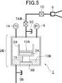
- the system diagram figure of the steam injection system (for experiment) concerning a 5th embodiment of the present invention.
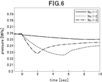
- the graph showing the change of the pressure in a container when a steam injection experiment is performed using the steam injection system of a comparative example.
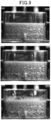
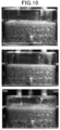
- the system diagram figure of the steam injection system (for experiment) concerning a 6th embodiment of the present invention The photograph showing the behavior of a liquid propellant when a steam injection experiment was performed using the steam injection system of a comparative example (from the top, nozzle diameter 0.4 mm, 0.6 mm, 0.8 mm). 9 is a photograph showing the behavior of liquid propellant when a vapor injection experiment is performed using the vapor injection system of FIG. 8 (from the top, nozzle diameters 0.6 mm, 0.8 mm, and 1.0 mm).
- the steam injection system according to the present invention is not limited to a specific specific configuration shown in each drawing and related description, and can be appropriately changed within the scope of the present invention.
- the vapor injection system may be configured by using three or more kinds of liquids that are insoluble in each other (in the configuration of FIG. 1, the liquid fuel storage containers 2A, 2B, 2C,. As many as the number of types are provided, and the pipes may be merged in the same manner as in the configuration of Fig. 1.)
- two types of inert gas are used. You may use above.
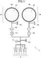
- FIG. 1 shows a system diagram example of a steam injection system 1 (propulsion unit) that can be used in a propulsion system for a small spacecraft according to the first embodiment of the present invention.
- the vapor injection system 1 includes liquid fuel storage containers 2A and 2B made of aluminum, SUS (stainless steel), and the like and liquid fuel storage containers 2A and 2B, which contain liquefied gases A and B that are insoluble in each other. Passes through injection and discharge valves 5A and 5B for injecting and discharging liquefied gases A and B, filters 6A and 6B for preventing impurities and liquid fuel from passing through, and filters 6A and 6B.
- the latch type solenoid valves 7A and 7B for controlling the movement of the vapors of the liquefied gases A and B to the propellant valve 7C side and the injection of the vapors of the liquefied gases A and B from the injection port 8 are controlled.
- An electromagnetic valve (propellant valve) 7C and an injection port 8 for injecting vapors of the liquefied gases A and B are provided.
- copper and SUS foam metals 3A and 3B having a porosity of about 95% are attached to the inner walls of the liquid fuel storage containers 2A and 2B using adhesives.
- Heaters 4A and 4B are respectively attached to the outer wall of 2B over the entire circumference.
- a line segment connecting each component represents a pipe.
- the steam injection system 1 is used for a pressure sensor 9 for detecting the pressure in the pipe, a ground test for injecting helium gas or the like with the propellant valve 7C closed to check for leaks, and the like.
- a discharge valve 5C is provided.
- the pressure in the space in which the vapor is stored in the liquid fuel storage containers 2A and 2B becomes higher than the saturated vapor pressure of the liquefied gases A and B.
- This gas pressure is monitored by a pressure sensor 9.
- the propellant propellant valve 7C is opened while the latch type electromagnetic valves 7A and 7B are opened, the combined steam is injected from the injection port 8 to the outside to generate thrust. Since the pressure at the start of injection is higher than the saturated vapor pressure of the liquefied gases A and B, the injection can be continued for a long time without generating cavitation.
- the vapor injection system 1 of FIG. 1 that operates using two types of liquefied gas (or liquid in a broad sense) has been described above.
- one type of liquefied gas (or a broad sense of liquid) and at least The vapor injection system 1 of FIG. 1 can be configured as a vapor injection system that operates using one kind of inert gas.
- one of the liquid fuel storage containers 2A and 2B is filled with at least one kind of inert gas (such as high-pressure GN2 or GHe) instead of the liquefied gas. It is not necessary to attach a foam metal to a storage container (inert gas storage container) filled with an inert gas.
- the vapor of the liquefied gas and the inert gas merge in the pipe, and the pressure in the space containing the vapor is stored. Becomes higher than the saturated vapor pressure of the liquefied gas.
- the propellant propellant valve 7C is opened while the latch type electromagnetic valves 7A and 7B are opened, the combined steam and inert gas are injected to the outside from the injection port 8 to generate thrust. Since the pressure at the start of injection is higher than the saturated vapor pressure of the liquefied gas, the injection can be continued for a long time without generating cavitation.
- the liquefied gases A and B are heated by the heaters 4A and 4B to recover the temperatures of these liquefied gases.
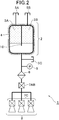
- FIG. 2 shows an example of a system diagram of a vapor injection system 1 (propulsion device) according to the second embodiment of the present invention configured using a single fluid storage container.
- the liquefied gases A and B which are insoluble in each other, or the liquefied gas A and at least one kind of inert gas are separated by a partition wall 10 (consisting of aluminum, SUS, etc.).
- Fluid storage containers 2 respectively housed in the spaces, and injection / discharge valves 5A and 5B for injecting (injecting) and discharging (exhausting) liquefied gas and inert gas into the fluid storage container 2,
- a filter 6 for preventing impurities and liquid fuel from passing through, and a latch-type electromagnetic for controlling the movement of liquefied gas vapor or inert gas that has passed through the filter toward the propellant valve 7C.
- foam metal 3A, 3B is attached to the inner wall of each space partitioned by the partition wall 10 (not required for the inner wall of the space containing the inert gas), and the outer wall has a heater. 4 is attached over the entire circumference.
- a line segment connecting each component represents a pipe.
- the steam injection system 1 is provided with a pressure sensor 9 that detects the pressure in the pipe, and an injection / discharge valve 5 ⁇ / b> C for use in a ground test or the like.
- the pressure in the space for storing the vapor in the fluid storage container 2 is higher than the saturated vapor pressure of the liquefied gas.
- This gas pressure is monitored by a pressure sensor 9.
- the injection can be continued for a long time without generating cavitation.
- the liquefied gas is heated by the heater 4 to recover the temperature of these liquefied gases.
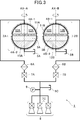
- FIG. 3 shows an example of a system diagram of the steam injection system 1 (propulsion unit) according to the third embodiment of the present invention configured using them.
- the steam injection system 1 includes liquid fuel storage containers 2A and 2B that contain liquefied gases A and B, which are insoluble in each other, and liquefied gases A and B with respect to the liquid fuel storage containers 2A and 2B.
- mesh bodies 11A and 11B made of SUS or the like are attached to the inner walls of the liquid fuel storage containers 2A and 2B using adhesives.
- the internal space of the liquid fuel storage containers 2A and 2B contains a space (in FIG. 3, The mesh bodies 11A and 11B are separated from each other) and a space (a lower side of the mesh bodies 11A and 11B in FIG. 3) (see FIG. 1, paragraph [0032] of Patent Document 3).
- foam metal 3A and 3B for holding liquid liquefied gases A and B, respectively, in the gaps are attached to the inner walls of the liquid fuel storage containers 2A and 2B adjacent to the nets 11A and 11B.
- the space for storing the liquid may be completely occupied by the foamed metals 3A and 3B.
- the metal foams 3A and 3B may be disposed only in a part of the space for storing the liquid, and the remaining space may be occupied by the liquid liquefied gases 13A and 13B.
- heaters 4A-1 and 4A-2 and 4B-1 and 4B-2 are attached to the outer walls of the liquid fuel storage containers 2A and 2B, respectively. Due to the heating of the heaters 4A-1 and 4B-1, the temperature of the internal space of the liquid fuel storage containers 2A and 2B is controlled so that the temperature of the space for storing the vapor is higher than the temperature of the space for storing the liquid. . As a result, reversal between the space for storing the vapor and the space for storing the liquid is prevented (see paragraph [0014] in Patent Document 3). Further, as described above, the temperature of each liquefied gas is recovered by heating during the injection interval by the heaters 4A-2 and 4B-2.
- the pipes extending from the liquid fuel storage containers 2A and 2B to the injection port 8 are appropriately provided with heaters so that the temperature in the pipes is kept higher than the temperature of the liquid fuel storage containers 2A and 2B. It is preferable to prevent the liquid from returning to the liquid (the same applies to other embodiments). Thereby, the temperature gradient which rises toward the space which accommodates vapor
- a plurality of flat plates 12A and 12B made of SUS or the like are attached to the inner walls of the liquid fuel storage containers 2A and 2B with an adhesive, and the liquid fuel storage containers 2A and 2B are respectively attached during the operation of the vapor injection system 1.
- the floating droplets can be captured by the flat plates 12A and 12B by rotating around the rotation axes AX-A and AX-B (using an arbitrary drive circuit (not shown) or the like). [0043]).
- the steam injection system 1 of FIG. 3 that operates using two types of liquefied gas has been described above.
- the steam injection system 1 operates using one type of liquefied gas and at least one type of inert gas.
- the liquid storage containers 2A and 2B have the same configuration except that the container (gas storage container) that stores the inert gas does not have to be provided with a net, a foam metal, a flat plate, or a heater. It is possible to operate.
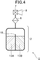
- FIG. 4 shows an example of a system diagram of a vapor injection system 1 according to a fourth embodiment of the present invention configured as a vapor injection spray.
- a steam injection system 1 is provided with a liquid storage container 2 (aluminum can, etc.) each provided with a partition wall 10 made of aluminum and containing liquefied gases A and B that are insoluble in each other, and impurities and liquids.
- the filter 6 for preventing the liquefied gas from passing, the nozzle controller 7 for controlling the liquefied gas A and B vapor from the injection port 8, and the liquefied gas A and B vapor are injected.
- an injection port 8 Liquid liquefied gases A and B (13A and 13B) are accommodated in the spaces separated by the partition walls 10, respectively.
- the steam injection system 1 of FIG. 4 that operates using two types of liquefied gas has been described above.
- the steam injection system 1 operates using one type of liquefied gas and at least one type of inert gas. It is possible to operate in the aspect. Specifically, if liquefied gas and at least one kind of inert gas are sealed in the liquid (fluid) storage container 2 in advance (the partition wall 10 is not necessary), the liquid is stored in the liquid storage container 2. Since the pressure in the space becomes higher than the saturated vapor pressure of the liquefied gas, it is possible to continue the injection for a long time without generating cavitation.
- a steam injection system 1 having the configuration shown in FIG. 5 was produced and an injection experiment was performed.
- a 0.1 L liquid fuel storage container 2A (made of acrylic) is placed inside a 1.0 L liquid fuel storage container 2B (made of acrylic) via a spacer 15 (made of aluminum). Connected.
- the liquid fuel storage container 2A is filled with 28% (mass percent concentration) ammonia water 13A, and the liquid fuel storage container 2B is filled with liquefied butane 13B (First, the liquid fuel storage container 2A is filled with ammonia water 13A.
- liquefied butane 13B is filled from the pouring / discharging valve 5B connected to the bottom of the liquid fuel storage container 2B, and each of the containers is filled with foam metal 3A, 3B made of nickel.
- the discharge valve 5C is for ground tests such as confirmation of leaks.
- the mixed vapor pressure of ammonia water and liquefied butane is monitored by the temperature sensor 14 and the pressure sensor 9 connected to the liquid fuel storage container 2B.
- External gas injection is performed by opening an electromagnetic valve 7 ⁇ / b> C connected immediately before the injection port (nozzle) 8.
- the performance of the steam injection system was evaluated from the following viewpoints: (1) Pressure of mixed vapor of ammonia water and liquefied butane measured from temperature sensor 14 and pressure sensor 9 connected to liquid fuel storage container 2B (2) Confirmed from image of high-speed camera (shooting speed: 120 fps) The measured value of the pressure sensor 9 at the time of occurrence of cavitation (Because the material of the liquid fuel storage containers 2A and 2B is made of acrylic resin, the presence or absence of cavitation from the liquid fuel contained in the container can be photographed. )
- FIG. 6 shows a change in pressure in the liquid fuel storage container 2B during the steam injection experiment.
- the solid line is the nozzle throat diameter 0.4 mm (No. 1-1)
- the broken line is 0.6 mm (No. 1-2)
- the alternate long and short dash line is 0.8 mm (No. 1-3).
- butane vapor pressure is a pressure P calculated from the initial temperature using the following Antoine equation (1) (T is an absolute temperature).
- the initial pressure of the liquid fuel storage container 2B is the saturated vapor pressure of liquefied butane, and the vapor injection is performed regardless of the nozzle throat diameter, that is, the pressure reduction speed. Immediately after that, it was confirmed that cavitation occurred.
- FIG. 7 shows changes in pressure in the liquid fuel storage container 2B during the vapor injection experiment.
- the solid line is the nozzle throat diameter 0.4 mm (No. 2-1)
- the broken line is 0.6 mm (No. 2-2)
- the alternate long and short dash line is 0.8 mm (No. 2-3).
- the pressure in the container before the injection was about 30 to 40 kPa higher than the saturated vapor pressure of liquefied butane.
- cavitation occurred from the bottom of the liquid fuel storage container 2B after falling below the saturated vapor pressure of the butane alone calculated from the temperature sensor 14 regardless of the decompression speed. Therefore, it was confirmed that the generation of cavitation by the vapor pressure of ammonia water can be delayed compared to the case of vapor injection of butane alone.
- an experimental steam injection system 1 having the configuration shown in FIG. 8 was produced.
- a microgravity experiment using a drop tower was conducted to confirm that the long-second injection performance was improved by suppressing cavitation.
- the injection test was performed in the same environment for the one-liquid type and the one-liquid + 1 gas type propulsion system, and the gas-liquid separation performance was compared.
- This experiment was conducted in a 50m drop tower in Akahira, Hokkaido.
- the gravity level is 10 ⁇ 3 G and the fall time is about 2.5 seconds.
- a foam metal 3 (ERG Duocel 40PPI6) was applied to a fluid storage container 2 made of 0.3 L polycarbonate, and liquid HFC134a was filled to the same height as the foam metal 3.
- the behavior of the liquid propellant in the fluid storage container 2 at the time of jetting was recorded by four pressure sensors 9A to 9D, one temperature sensor 14, and a high-speed camera 16 (shooting speed: 120 fps).
- the pressure sensor measures the ledge portion (PG), the liquid portions (PL1, PL2) in which the vapor of the HFC 134a is accommodated, and the nozzle chamber portion (PC) of the injection port 8.
- the temperature sensor measures the temperature of the ledge (gas). The flow rate was adjusted by changing the nozzle throat diameter.
- FIG. 9 shows a photograph of the liquid propellant at the time of the injection test using HFC134a alone (2.0 seconds after the start of dropping) (from the top, nozzle diameters 0.4 mm, 0.6 mm, 0.8 mm). From FIG. 9, it can be confirmed that the liquid propellant flows out of the foam metal in the test case of ⁇ 0.8 mm.
- the pressure history measured by the pressure sensors 9A to 9D the pressure history of the case where the liquid propellant is held in the foam metal is monotonously decreased during the injection, but the liquid propellant has flowed out. No. In the case of 1-3, the pressure recovered in the second half of the injection. This is thought to be due to the increase in pressure due to the addition of vaporization by cavitation to vaporization by evaporation.
- the steam injection system of the present invention can be used for any device, method, system, etc. for stably performing steam injection, including a propellant and spray for a small planetary propulsion system.
Landscapes
- Engineering & Computer Science (AREA)
- Chemical & Material Sciences (AREA)
- Combustion & Propulsion (AREA)
- Mechanical Engineering (AREA)
- General Engineering & Computer Science (AREA)
- Remote Sensing (AREA)
- Aviation & Aerospace Engineering (AREA)
- Physics & Mathematics (AREA)
- Plasma & Fusion (AREA)
- Filling Or Discharging Of Gas Storage Vessels (AREA)
Priority Applications (2)
| Application Number | Priority Date | Filing Date | Title |
|---|---|---|---|
| US15/310,419 US10870502B2 (en) | 2014-05-13 | 2015-05-11 | Vapor jet system enabling jetting for many seconds using multiple kinds of mutually insoluble liquid gases as fuel |
| EP15792862.3A EP3144530B1 (en) | 2014-05-13 | 2015-05-11 | Vapor jet system enabling jetting for many seconds using multiple kinds of mutually insoluble liquid gases as fuel |
Applications Claiming Priority (2)
| Application Number | Priority Date | Filing Date | Title |
|---|---|---|---|
| JP2014-099693 | 2014-05-13 | ||
| JP2014099693A JP6507400B2 (ja) | 2014-05-13 | 2014-05-13 | 互いに非可溶性である複数種類の液化ガスを燃料に用いた、長秒時噴射を可能とする蒸気噴射システム |
Publications (1)
| Publication Number | Publication Date |
|---|---|
| WO2015174366A1 true WO2015174366A1 (ja) | 2015-11-19 |
Family
ID=54479905
Family Applications (1)
| Application Number | Title | Priority Date | Filing Date |
|---|---|---|---|
| PCT/JP2015/063463 Ceased WO2015174366A1 (ja) | 2014-05-13 | 2015-05-11 | 互いに非可溶性である複数種類の液化ガスを燃料に用いた、長秒時噴射を可能とする蒸気噴射システム |
Country Status (4)
| Country | Link |
|---|---|
| US (1) | US10870502B2 (enExample) |
| EP (1) | EP3144530B1 (enExample) |
| JP (1) | JP6507400B2 (enExample) |
| WO (1) | WO2015174366A1 (enExample) |
Cited By (2)
| Publication number | Priority date | Publication date | Assignee | Title |
|---|---|---|---|---|
| CN106184823A (zh) * | 2016-07-06 | 2016-12-07 | 浙江大学 | 一种自主汽化管理方法及液氨微推进系统 |
| JP2018091529A (ja) * | 2016-12-01 | 2018-06-14 | 株式会社日本製鋼所 | 飛翔体 |
Families Citing this family (5)
| Publication number | Priority date | Publication date | Assignee | Title |
|---|---|---|---|---|
| JP6991542B2 (ja) * | 2016-03-23 | 2022-02-03 | 国立研究開発法人宇宙航空研究開発機構 | 噴射システム |
| US10883449B2 (en) | 2016-03-23 | 2021-01-05 | Japan Aerospace Exploration Agency | Jet system |
| US11053027B2 (en) * | 2018-10-01 | 2021-07-06 | The Boeing Company | Space-based gas supply system |
| CN111114835B (zh) * | 2019-12-24 | 2023-06-23 | 兰州空间技术物理研究所 | 一种用于电推进的液体推进剂供给组件及电推进系统 |
| CN111441876A (zh) * | 2020-04-01 | 2020-07-24 | 北京深蓝航天科技有限公司 | 一种用于多台发动机并联的液体火箭燃料输送结构 |
Citations (7)
| Publication number | Priority date | Publication date | Assignee | Title |
|---|---|---|---|---|
| JPS62291454A (ja) * | 1986-04-16 | 1987-12-18 | マットラ マーコニ スペース ユーケイ リミテッド | スラスタ− |
| JP2004044480A (ja) * | 2002-07-11 | 2004-02-12 | Natl Space Development Agency Of Japan | 2液式エンジンおよび2液式エンジンを搭載したロケット |
| JP2008144588A (ja) * | 2006-12-06 | 2008-06-26 | Japan Aerospace Exploration Agency | 亜酸化窒素を用いたスラスタ装置 |
| JP2011183841A (ja) * | 2010-03-04 | 2011-09-22 | Japan Aerospace Exploration Agency | 推進薬タンク及びこの推進薬タンクを用いた蒸気噴射装置 |
| WO2013158195A2 (en) * | 2012-01-30 | 2013-10-24 | Firestar Engineering, Llc | In-tank propellant mixing |
| WO2013188393A1 (en) * | 2012-06-12 | 2013-12-19 | Georgia Tech Research Corporation | Dual use hydrazine propulsion thruster system |
| WO2014024966A1 (ja) * | 2012-08-10 | 2014-02-13 | 株式会社Ihi | 蒸気噴射装置及び宇宙機 |
Family Cites Families (4)
| Publication number | Priority date | Publication date | Assignee | Title |
|---|---|---|---|---|
| US3854905A (en) * | 1972-04-24 | 1974-12-17 | Rca Corp | Storage system for two phase fluids |
| JP5352821B2 (ja) | 2008-03-10 | 2013-11-27 | 独立行政法人 宇宙航空研究開発機構 | 液体燃料貯蔵用容器及び該容器を用いた蒸気噴射システム |
| JP5509428B2 (ja) | 2010-03-04 | 2014-06-04 | 独立行政法人 宇宙航空研究開発機構 | 蒸気噴射装置 |
| US9108144B2 (en) * | 2013-05-21 | 2015-08-18 | Astrium Gmbh | Tank for separating liquid from gas under weightless conditions |
-
2014
- 2014-05-13 JP JP2014099693A patent/JP6507400B2/ja active Active
-
2015
- 2015-05-11 US US15/310,419 patent/US10870502B2/en active Active
- 2015-05-11 WO PCT/JP2015/063463 patent/WO2015174366A1/ja not_active Ceased
- 2015-05-11 EP EP15792862.3A patent/EP3144530B1/en active Active
Patent Citations (7)
| Publication number | Priority date | Publication date | Assignee | Title |
|---|---|---|---|---|
| JPS62291454A (ja) * | 1986-04-16 | 1987-12-18 | マットラ マーコニ スペース ユーケイ リミテッド | スラスタ− |
| JP2004044480A (ja) * | 2002-07-11 | 2004-02-12 | Natl Space Development Agency Of Japan | 2液式エンジンおよび2液式エンジンを搭載したロケット |
| JP2008144588A (ja) * | 2006-12-06 | 2008-06-26 | Japan Aerospace Exploration Agency | 亜酸化窒素を用いたスラスタ装置 |
| JP2011183841A (ja) * | 2010-03-04 | 2011-09-22 | Japan Aerospace Exploration Agency | 推進薬タンク及びこの推進薬タンクを用いた蒸気噴射装置 |
| WO2013158195A2 (en) * | 2012-01-30 | 2013-10-24 | Firestar Engineering, Llc | In-tank propellant mixing |
| WO2013188393A1 (en) * | 2012-06-12 | 2013-12-19 | Georgia Tech Research Corporation | Dual use hydrazine propulsion thruster system |
| WO2014024966A1 (ja) * | 2012-08-10 | 2014-02-13 | 株式会社Ihi | 蒸気噴射装置及び宇宙機 |
Non-Patent Citations (1)
| Title |
|---|
| See also references of EP3144530A4 * |
Cited By (2)
| Publication number | Priority date | Publication date | Assignee | Title |
|---|---|---|---|---|
| CN106184823A (zh) * | 2016-07-06 | 2016-12-07 | 浙江大学 | 一种自主汽化管理方法及液氨微推进系统 |
| JP2018091529A (ja) * | 2016-12-01 | 2018-06-14 | 株式会社日本製鋼所 | 飛翔体 |
Also Published As
| Publication number | Publication date |
|---|---|
| EP3144530A1 (en) | 2017-03-22 |
| JP6507400B2 (ja) | 2019-05-08 |
| JP2015214956A (ja) | 2015-12-03 |
| US10870502B2 (en) | 2020-12-22 |
| EP3144530B1 (en) | 2024-02-14 |
| EP3144530A4 (en) | 2018-01-10 |
| US20170073089A1 (en) | 2017-03-16 |
Similar Documents
| Publication | Publication Date | Title |
|---|---|---|
| WO2015174366A1 (ja) | 互いに非可溶性である複数種類の液化ガスを燃料に用いた、長秒時噴射を可能とする蒸気噴射システム | |
| JP5352821B2 (ja) | 液体燃料貯蔵用容器及び該容器を用いた蒸気噴射システム | |
| JP5145062B2 (ja) | 極低温液体および貯蔵可能な燃料を貯蔵するためのタンク | |
| JP6016905B2 (ja) | 極低温スラスタアセンブリ | |
| JP6586657B2 (ja) | 蒸気噴射システム | |
| EP2366626B1 (en) | Liquid propellant tank and vapor jet emitting device including same | |
| JP5509429B2 (ja) | 推進薬タンク及びこの推進薬タンクを用いた蒸気噴射装置 | |
| Darr et al. | Optimal liquid acquisition device screen weave for a liquid hydrogen fuel depot | |
| CN101596939A (zh) | 用于储存低温液体和能储存的动力燃料的容器 | |
| JP6590502B2 (ja) | 宇宙航行体用の推進薬タンク及び宇宙航行体 | |
| JP4934672B2 (ja) | 極低温液体用の推進剤タンク | |
| US11945606B1 (en) | Electric propulsion based spacecraft propulsion systems and methods utilizing multiple propellants | |
| EP2761159B1 (en) | Propulsion system | |
| JP2004044480A (ja) | 2液式エンジンおよび2液式エンジンを搭載したロケット | |
| US11346306B1 (en) | Chemical and cold gas propellant systems and methods | |
| JP6991542B2 (ja) | 噴射システム | |
| Dominick et al. | Fluid acquisition and resupply experiments on space shuttle flights STS-53 and STS-57 | |
| Chujo et al. | Development of solid-gas equilibrium propulsion system for small spacecraft | |
| RU2522536C1 (ru) | Способ газификации жидкого ракетного топлива в баке ракеты и устройство для его реализации | |
| KR101022388B1 (ko) | 누센 펌프를 이용한 인공위성 추진 장치 및 추진 방법 | |
| Yamamoto et al. | New Thruster System for Small Satellite: Gas-Liquid Equilibrium Thruster | |
| Chujo et al. | Development of Bipropellant Gas-Liquid Equilibrium Propulsion System | |
| JP6063817B2 (ja) | 軌道内で液体を分離するためのタンク | |
| Behruzi et al. | Cryogenic propellant management during ballistic flight phases | |
| Motooka et al. | Microgravity Evaluation of Advantages of Porous Metal in the Gas-Liquid Equilibrium Thruster for Small Spacecraft |
Legal Events
| Date | Code | Title | Description |
|---|---|---|---|
| 121 | Ep: the epo has been informed by wipo that ep was designated in this application |
Ref document number: 15792862 Country of ref document: EP Kind code of ref document: A1 |
|
| WWE | Wipo information: entry into national phase |
Ref document number: 15310419 Country of ref document: US |
|
| REEP | Request for entry into the european phase |
Ref document number: 2015792862 Country of ref document: EP |
|
| WWE | Wipo information: entry into national phase |
Ref document number: 2015792862 Country of ref document: EP |
|
| NENP | Non-entry into the national phase |
Ref country code: DE |