WO2015174156A1 - 製氷装置 - Google Patents
製氷装置 Download PDFInfo
- Publication number
- WO2015174156A1 WO2015174156A1 PCT/JP2015/060202 JP2015060202W WO2015174156A1 WO 2015174156 A1 WO2015174156 A1 WO 2015174156A1 JP 2015060202 W JP2015060202 W JP 2015060202W WO 2015174156 A1 WO2015174156 A1 WO 2015174156A1
- Authority
- WO
- WIPO (PCT)
- Prior art keywords
- ice
- unit
- storage unit
- storage
- making device
- Prior art date
- Legal status (The legal status is an assumption and is not a legal conclusion. Google has not performed a legal analysis and makes no representation as to the accuracy of the status listed.)
- Ceased
Links
Images



Classifications
-
- F—MECHANICAL ENGINEERING; LIGHTING; HEATING; WEAPONS; BLASTING
- F25—REFRIGERATION OR COOLING; COMBINED HEATING AND REFRIGERATION SYSTEMS; HEAT PUMP SYSTEMS; MANUFACTURE OR STORAGE OF ICE; LIQUEFACTION SOLIDIFICATION OF GASES
- F25C—PRODUCING, WORKING OR HANDLING ICE
- F25C1/00—Producing ice
Definitions
- the present invention relates to an ice making device.
- an apparatus described in Patent Document 1 is known as an apparatus for producing sorbet-like or snow-like ice from salt water.
- the ice making device of Patent Document 1 has an ice accumulation / growth layer, a seawater storage layer, and a screen that can be moved up and down arranged in the ice accumulation / growth layer.
- the ice produced by a special ice maker is stored on the screen in the ice accumulation / growth layer. Further, the ice stored on the screen can be taken out by raising the screen.
- An object of the present invention is to provide an ice making device capable of reducing the installation space in the height direction.
- a first reservoir that has an opening at the bottom and stores brine and ice;
- a separation unit that separates the brine and the ice in the first storage unit;
- a second reservoir that stores the brine separated by the separator;
- a feeding unit that feeds the brine stored in the second storage unit to a cooling unit;
- An injection part for injecting the brine, which is cooled by the cooling part and partially becomes the ice, into the first storage part,
- the ice making device wherein the first storage part is movable in a direction intersecting a vertical direction with respect to the separation part.
- first reservoir having an opening at the bottom and storing brine and ice; A separation unit that separates the brine and the ice in the first storage unit; A second reservoir that stores the brine separated by the separator; A feeding unit that feeds the brine stored in the second storage unit to a cooling unit; An injection part for injecting the brine, which is cooled by the cooling part and partially becomes the ice, into the first storage part,
- the ice making device wherein the first storage unit is rotatable about an axis that intersects the vertical direction with respect to the second storage unit.
- the ice making device according to any one of (3), (6), and (7), further including a transport unit configured to transport the ice accumulated in the accumulation unit.
- the separation part has a plate shape and includes a main body having a through hole penetrating in the thickness direction, and a filtering member disposed in the through hole.
- the ice making device according to any one of the above.
- the ice stored in the first storage unit can be taken out by sliding (or rotating) the first storage unit in the lateral direction, which is necessary for installing the device.
- the height can be kept low. That is, according to the present invention, the installation space in the height direction can be reduced.
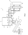
- FIG. 1 is a cross-sectional view showing an ice making device according to a first embodiment of the present invention.
- FIG. 2 is a cross-sectional view showing a state where the first storage unit of the ice making device shown in FIG. 1 is slid.
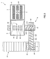
- FIG. 3 is a top view of the ice making device shown in FIG.
- FIG. 4 is a sectional view showing an ice making device according to the second embodiment of the present invention.
- FIG. 5 is a cross-sectional view showing a state where the first storage unit of the ice making device shown in FIG. 4 is rotated.
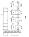
- FIG. 6 is a top view showing an application example of the ice making device of the present invention.
- FIG. 1 is a cross-sectional view showing an ice making device according to a first embodiment of the present invention.
- FIG. 2 is a cross-sectional view showing a state where the first storage unit of the ice making device shown in FIG. 1 is slid.
- FIG. 3 is a top view of the ice making device shown in FIG.
- the upper side in FIG. 1 is also referred to as “upper” and the lower side is also referred to as “lower”.
- the ice making device 1 shown in FIG. 1 to FIG. 3 is ice for mainly storing salty fish and shellfish (including squid, octopus, shrimp, etc.) SF, and has a fine grain and snowy shape ( This is an apparatus for producing soft ice I in the form of a sherbet.
- Such an ice making device 1 includes a first storage unit 2, a separation unit 3 provided below the first storage unit 2, a second storage unit 4 provided below the separation unit 3, and a cooling unit ( (Cooling unit) 10, a feeding unit 5 that connects the second storage unit 4 to the cooling unit 10, an injection unit 6 that connects the cooling unit 10 to the first storage unit 2, and a discharge unit connected to the second storage unit 4 7, a stacking unit 8 provided side by side with the second storage unit 4, and a transport unit 9 provided below the stacking unit 8.
- a cooling unit (Cooling unit) 10
- a feeding unit 5 that connects the second storage unit 4 to the cooling unit
- an injection unit 6 that connects the cooling unit 10 to the first storage unit 2
- a discharge unit connected to the second storage unit 4 7
- a stacking unit 8 provided side by side with the second storage unit 4
- a transport unit 9 provided below the stacking unit 8.
- the first storage unit 2 is a tank for storing salt water (brine) W, which is a raw material for the ice I, and storing ice I generated from the salt water W.
- the salt water W is not particularly limited.
- salt water having a salt concentration of about 1.0% to 5.0% can be used, and seawater can be preferably used.
- seawater can be preferably used.
- ice I having a salinity of about 1% can be produced, and ice I is suitable for cold storage of seafood SF.
- the first reservoir 2 has a frame shape, and has an upper opening 21 that opens to the top and a bottom opening 22 that opens to the bottom. Further, the bottom opening 22 is closed by the separation unit 3 and the second storage unit 4 provided on the lower side of the first storage unit 2. Thereby, the salt water W can be stored in the 1st storage part 2.
- a seal member (not shown) is disposed between the first storage unit 2 and the separation unit 3 or between the separation unit 3 and the second storage unit 4, and thereby the first storage unit 2 and the separation unit 3. Bleeding of the salt water W from between the separation part 3 and the second storage part 4 is prevented.
- the capacity of the first storage unit 2 is not particularly limited, but is preferably about 500 liters to 1000 liters, for example. Thereby, excessive enlargement (especially height increase) of the apparatus can be prevented, and a sufficient amount of ice I can be stored in the first storage unit 2.
- the separation unit 3 positioned below the first storage unit 2 is a member for introducing substantially only the salt water W from the first storage unit 2 into the second storage unit 4.
- the separation unit 3 has a plate shape and includes a main body 31 having a plurality of through holes 311 penetrating in the plate thickness direction, and a filtering member 32 disposed in the through hole 311. Thereby, the structure of the isolation
- the filtering member 32 is not particularly limited as long as it allows passage of the salt water W and restricts the passage of ice (ice crystals) I.
- various porous bodies such as nonwoven fabrics, woven fabrics, knitted fabrics, sponges, etc. Can be used.
- the second storage unit 4 positioned below the separation unit 3 is a tank that stores the salt water W filtered by the separation unit 3.
- a feed unit 5 and a discharge unit 7 are provided at the bottom of the second storage unit 4.
- the salt water W in the 2nd storage part 4 can be supplied to the cooling unit 10 via the supply part 5, and the salt water in the 2nd storage part 4 is discharged
- the discharge portion 7 is provided with a valve (not shown) so that the salt water W can be discharged by opening the valve.
- the ice making device 1 has the second storage unit 4, but omits the second storage unit 4.
- the feeding unit 5 and the discharge unit 7 are directly connected to the through-hole 311 of the separation unit 3. , You may connect.
- the salt water W in the second storage unit 4 is fed to the cooling unit 10 via the feeding unit 5.
- the cooling unit 10 is a unit that generates ice I by cooling the salt water W supplied from the feeding unit 5.
- the cooling unit 10 includes an ice generator (heat exchanger) 101 that generates ice I from the salt water W, a motor 102 that drives the ice generator 101, and a refrigerator 103 that circulates the refrigerant C through the ice generator 101. Yes.
- the salt water W supplied to the ice generator 101 through the supply unit 5 is gradually cooled by heat exchange with the refrigerant C supplied from the refrigerator 103, and a part of the fine ice (ice crystals) containing salt is contained. ) I.
- the salt water W containing the ice I is discharged from the ice generator 101 and then injected into the first storage unit 2 through the injection unit 6.
- the fine ice I generated by the cooling unit 10 is gradually stored in the first storage unit 2.
- the injection unit 6 is provided through the second storage unit 4 and the separation unit 3, and injects salt water W containing ice I from the center of the bottom of the first storage unit 2.
- the injection part 6 injects the salt water W containing the ice I directly into the salt water W stored in the first storage part 2.
- pouring can be relieved.
- a convection can be generated in the salt water W in the 1st storage part 2, and the coupling
- pouring part 6 is not specifically limited,
- the salt water W may be inject
- the salt water W in the second storage unit 4 can be supplied to the cooling unit 10 by the supply unit 5, while the salt water W in the second storage unit 4 passes the discharge unit 7. Can be discharged to the outside of the apparatus. Thereby, water can be extracted from the ice I stored in the first storage part 2 located above, and the water of the ice I stored in the first storage part 2 can be cut. Therefore, softer ice I with less moisture can be produced.
- the discharge unit 7 may forcibly remove the salt water W from the first reservoir using a suction means such as a suction pump, or may naturally remove the salt water W from the first reservoir. Good.
- the 1st storage part 2 intersects with the isolation
- the accumulation unit 8 is located below the first storage unit 2 in a state in which the first storage unit 2 is slid with respect to the separation unit 3. Therefore, when a sufficient amount of ice I is stored in the first storage part 2 and the salt water W is discharged from the discharge part 7, the first storage part 2 is slid as shown in FIG. The ice I stored in the water drops from the bottom opening 22 and is accumulated in the accumulation unit 8.
- the “substantially horizontal direction” is meant to include not only the horizontal direction but also a direction slightly inclined (for example, about ⁇ 10 °) with respect to the horizontal.
- the accumulating unit 8 includes an accumulating unit main body 81 that receives the ice I falling from the first storage unit 2 and an agitating unit 82 that agitates the ice accumulated on the accumulating unit main body 81.
- the stacking unit main body 81 has a tapered shape with inclined sidewalls, and has an upper opening 811 that opens upward and a lower opening 812 that opens downward. Therefore, the ice I falling from the first storage unit 2 to the stacking unit 8 falls to the stacking unit main body 81 via the upper opening 811, slides down the inclined surface, and falls downward from the lower opening 812.
- the stirring unit 82 is provided in front of (above) the lower opening 812, and the ice I stirred by the stirring unit 82 falls from the lower opening 812. Thereby, softer ice I can be dropped from the lower opening 812.
- the configuration of the agitating unit 82 is not particularly limited as long as the ice I can be agitated, but in the present embodiment, a plurality of rotating bodies 821 having stirring blades are arranged, and each rotating body 821 is arranged. The ice can be stirred by rotating.
- the transport unit 9 of the present embodiment includes a first transport unit 91 that transports the ice I in the horizontal direction, and a second transport unit 92 that transports the ice I transported by the first transport unit 91 upward. Yes.
- the first and second transport units 91 and 92 include screw-like blades 912 and 922 on the circumferential surfaces of the elongated rotors 911 and 921. The ice I is conveyed by rotating around the axis.
- the configuration of the transport unit 9 is not limited to the above configuration as long as the ice I can be transported to a predetermined position, and for example, a belt conveyor or the like may be used. Moreover, the conveyance part 9 should just be provided as needed, and may be abbreviate
- a belt conveyor 20 is provided below the tip of the second transport unit 92, and the belt 30 packed with the seafood SF is transported by the belt conveyor 20. Therefore, the ice I transported to the tip of the second transport unit 92 falls and fits in the box 30, whereby the seafood SF is covered with the ice I. Then, the seafood SF is packaged in a state suitable for maintaining freshness by leveling the ice I and covering the ice I.
- the ice making device 1 since the first storage unit 2 is configured to collect the ice I in the first storage unit 2 by moving in a substantially horizontal direction, the device is installed (operated). ) Can be kept low. For this reason, the ceiling height restriction is relaxed, and it is easy to arrange indoors.
- FIG. 4 is a cross-sectional view showing an ice making device according to a second embodiment of the present invention.
- FIG. 5 is a cross-sectional view showing a state where the first storage unit of the ice making device shown in FIG. 4 is rotated.
- the ice making device of the second embodiment is the same as the ice making device of the first embodiment described above except that the configuration of the first storage unit is different.
- symbol is attached
- the first storage unit 2 and the separation unit 3 are fixed, and these can rotate integrally around a rotation axis J that is substantially horizontal with respect to the second storage unit 4. Is provided. And in the state which rotated the 1st storage part 2 and the separation part 3 with respect to the 2nd storage part 4, as shown in FIG. 5, the accumulation
- substantially horizontal means not only horizontal but also a direction slightly inclined (for example, about ⁇ 10 °) with respect to the horizontal.
- Such an ice making device 1 is configured to collect the ice I in the first storage unit 2 as the first storage unit 2 rotates. Therefore, as in the first embodiment described above, the height required to install (operate) the apparatus can be kept low, the ceiling height restriction is relaxed, and it is easy to arrange indoors.
- freezer and freezer of this invention were demonstrated based on embodiment of illustration, this invention is not limited to this.
- the configuration of each part can be replaced with any configuration that exhibits the same function, and any configuration can be added.
- fish and shellfish have been described as an example of an object to be stored in a cold state.
- the object to be stored in a cold state is not limited to this.
- fruits such as strawberries, apples, bananas, and tangerines.
- fresh food such as vegetables such as cabbage, lettuce, cucumber, and tomato, beef, pork, chicken and horse meat, and processed foods obtained by processing (cooking) these fresh foods.
- a plurality of ice making devices 1 are arranged side by side, and the transport unit 9 is arranged. May be configured in common.
- the transport unit 9 in common, for example, by shifting the generation completion time of the ice I of each ice making device 1, the ice I can be generated without interruption.
- the transport unit 9 in common, the installation space for the apparatus can be kept small.
- the configuration in which the ice I is generated using the salt water W as the brine in order to cool and preserve the fish and shellfish SF containing salt is described.
- the ice I generated from the salt water W may not be suitable for the cold storage.
- a glycol aqueous solution such as ethylene glycol or propylene glycol may be used, and the ice I may be generated using such a glycol aqueous solution.
- the ice making device of the present invention has an opening at the bottom, and is separated by a first storage unit that stores brine and ice, a separation unit that separates the brine and ice in the first storage unit, and the separation unit.
- the second storage part for storing the brine
- the feeding part for feeding the brine stored in the second storage part to the cooling part
- the cooling part cooled down to become the ice.
- An injection part for injecting the brine into the first storage part wherein the first storage part is movable in a direction intersecting a vertical direction with respect to the separation part.
- the ice making device of the present invention has industrial applicability.
Landscapes
- Engineering & Computer Science (AREA)
- Physics & Mathematics (AREA)
- Mechanical Engineering (AREA)
- Thermal Sciences (AREA)
- General Engineering & Computer Science (AREA)
Abstract
製氷装置1は、底部に開口を有し、塩水Wおよび氷Iを貯留する第1貯留部2と、第1貯留部2内の塩水Wと氷Iを分離する分離部3と、分離部3により分離された塩水Wを貯留する第2貯留部4と、第2貯留部4に貯留された塩水Wを冷却ユニット10に送給する送給部5と、冷却ユニット10によって冷却され、一部が氷Iとなった塩水Wを第1貯留部2に注入する注入部6と、を有し、第1貯留部2は、分離部3に対して水平方向に移動可動である。
Description
本発明は、製氷装置に関する。
従来から、魚介類の鮮度を保つために、この魚介類を塊状の氷で冷やすことが行われていた。しかしながら、塊状の氷では海上運送、陸上運送中の振動で塊状氷によって海水魚が損傷することや、塊状氷が融けて真水となり魚介類の鮮度が落ちること等から、近年では、塩水(ブライン)を冷却することにより生成されたシャーベット状または雪状の氷で魚介類を冷やすことが行われつつある。
そして、塩水からシャーベット状または雪状の氷を製造する装置として、例えば、特許文献1に記載の装置が知られている。特許文献1の製氷装置は、氷集積・成長層と、海水貯蔵層と、氷集積・成長層内に配置された昇降自在のスクリーンとを有し、海水貯蔵層に貯蔵された海水を特殊製氷機に送り、特殊製氷機により製造された氷を氷集積・成長層内のスクリーン上に収納するようになっている。また、スクリーン上に溜められた氷は、スクリーンを上昇させることで、取り出すことができるようになっている。
しかしながら、このような製氷装置では、上述したように、スクリーンを上昇させることで氷を取り出すため、氷を取り出すための空間を製氷装置の上方に確保する必要がある。したがって、室内に設置する場合には天井高に制限が加わり、装置の実用性が低下する。
本発明の目的は、高さ方向の設置スペースを低減することのできる製氷装置を提供することにある。
このような目的は、下記の本発明により達成される。
(1) 底部に開口を有し、ブラインおよび氷を貯留する第1貯留部と、
前記第1貯留部内の前記ブラインと前記氷を分離する分離部と、
前記分離部により分離された前記ブラインを貯留する第2貯留部と、
前記第2貯留部に貯留された前記ブラインを冷却部に送給する送給部と、
前記冷却部によって冷却され、一部が前記氷となった前記ブラインを前記第1貯留部に注入する注入部と、を有し、
前記第1貯留部は、前記分離部に対して鉛直方向と交わる方向に移動可動であることを特徴とする製氷装置。
(1) 底部に開口を有し、ブラインおよび氷を貯留する第1貯留部と、
前記第1貯留部内の前記ブラインと前記氷を分離する分離部と、
前記分離部により分離された前記ブラインを貯留する第2貯留部と、
前記第2貯留部に貯留された前記ブラインを冷却部に送給する送給部と、
前記冷却部によって冷却され、一部が前記氷となった前記ブラインを前記第1貯留部に注入する注入部と、を有し、
前記第1貯留部は、前記分離部に対して鉛直方向と交わる方向に移動可動であることを特徴とする製氷装置。
(2) 前記第1貯留部は、略水平方向に移動可能である上記(1)に記載の製氷装置。
(3) 前記第1貯留部内の氷を集積する集積部を有し、
前記第1貯留部が前記分離部に対して移動すると、前記第1貯留部内の氷が前記開口から落下して前記集積部に集積される上記(1)または(2)に記載の製氷装置。
前記第1貯留部が前記分離部に対して移動すると、前記第1貯留部内の氷が前記開口から落下して前記集積部に集積される上記(1)または(2)に記載の製氷装置。
(4) 底部に開口を有し、ブラインおよび氷を貯留する第1貯留部と、
前記第1貯留部内の前記ブラインと前記氷を分離する分離部と、
前記分離部により分離された前記ブラインを貯留する第2貯留部と、
前記第2貯留部に貯留された前記ブラインを冷却部に送給する送給部と、
前記冷却部によって冷却され、一部が前記氷となった前記ブラインを前記第1貯留部に注入する注入部と、を有し、
前記第1貯留部は、前記第2貯留部に対して鉛直方向と交わる軸まわりに回動可能であることを特徴とする製氷装置。
前記第1貯留部内の前記ブラインと前記氷を分離する分離部と、
前記分離部により分離された前記ブラインを貯留する第2貯留部と、
前記第2貯留部に貯留された前記ブラインを冷却部に送給する送給部と、
前記冷却部によって冷却され、一部が前記氷となった前記ブラインを前記第1貯留部に注入する注入部と、を有し、
前記第1貯留部は、前記第2貯留部に対して鉛直方向と交わる軸まわりに回動可能であることを特徴とする製氷装置。
(5) 前記第1貯留部は、略水平な前記軸まわりに回動可能である上記(4)に記載の製氷装置。
(6) 前記第1貯留部内の氷を集積する集積部を有し、
前記第1貯留部が前記第2貯留部に対して回動すると、前記第1貯留部内の氷が前記上部側の開口から落下して前記集積部に集積される上記(4)または(5)に記載の製氷装置。
前記第1貯留部が前記第2貯留部に対して回動すると、前記第1貯留部内の氷が前記上部側の開口から落下して前記集積部に集積される上記(4)または(5)に記載の製氷装置。
(7) 前記集積部には、前記氷を撹拌する撹拌部が設けられている上記(3)または(6)に記載の製氷装置。
(8) 前記集積部に集積された前記氷を搬送する搬送部を有する上記(3)、(6)および(7)のいずれかに記載の製氷装置。
(9) 前記分離部は、板状をなし、板厚方向に貫通する貫通孔を有する本体と、前記貫通孔に配置されたろ過部材とを有している上記(1)ないし(8)のいずれかに記載の製氷装置。
本発明によれば、第1貯留部を横方向にスライドさせることで(または回動させることで)、第1貯留部に溜まった氷を取り出すことができるため、装置を設置するのに必要な高さを低く抑えることができる。すなわち、本発明によれば、高さ方向の設置スペースを低減することができる。
以下、本発明の製氷装置の好適な実施形態について、添付図面を参照しつつ詳細に説明する。
<第1実施形態>
まず、本発明の第1実施形態に係る製氷装置について説明する。
まず、本発明の第1実施形態に係る製氷装置について説明する。
図1は、本発明の第1実施形態に係る製氷装置を示す断面図である。図2は、図1に示す製氷装置の第1貯留部をスライドさせた状態を示す断面図である。図3は、図1に示す製氷装置の上面図である。なお、以下では、説明の便宜上、図1中の上側を「上」とも言い、下側を「下」とも言う。
図1ないし図3に示す製氷装置1は、主に、塩分を含んだ魚介類(イカ、タコ、エビ等を含む)SFを冷却保存するための氷であって、粒が細かく、雪状(シャーベット状)で柔らかい氷Iを製造する装置である。このような製氷装置1は、第1貯留部2と、第1貯留部2の下方に設けられた分離部3と、分離部3の下方に設けられた第2貯留部4と、冷却ユニット(冷却部)10と、第2貯留部4を冷却ユニット10に繋ぐ送給部5と、冷却ユニット10を第1貯留部2に繋ぐ注入部6と、第2貯留部4に接続された排出部7と、第2貯留部4と並んで設けられた集積部8と、集積部8の下方に設けられた搬送部9と、を有している。
第1貯留部2は、氷Iの原料となる塩水(ブライン)Wを貯留するとともに、この塩水Wから生成された氷Iを貯留するための槽である。なお、塩水Wとしては、特に限定されないが、例えば、塩分濃度が1.0%~5.0%程度の塩水を用いることができ、海水を好適に用いることができる。この程度の塩水を用いることで、塩分濃度が約1%程度の氷Iを製造することができ、氷Iが魚介類SFの冷却保存に適したものとなる。
このような第1貯留部2は、枠状をなし、上部に開放する上部開口21と、底部に開放する底部開口22とを有している。また、底部開口22は、第1貯留部2の下側に設けられた分離部3および第2貯留部4によって塞がれている。これにより、第1貯留部2に塩水Wを貯留することができるようになっている。また、第1貯留部2と分離部3との間や分離部3と第2貯留部4との間には図示しないシール部材が配置され、これにより、第1貯留部2と分離部3の間や分離部3と第2貯留部4の間からの塩水Wの滲み出しが防止されている。なお、第1貯留部2の容量としては、特に限定されないが、例えば、500リットル~1000リットル程度であることが好ましい。これにより、装置の過度な大型化(特に高背化)を防止することができるともに、十分な量の氷Iを第1貯留部2に貯留することができる。
このような第1貯留部2の下側に位置する分離部3は、第1貯留部2から実質的に塩水Wのみを第2貯留部4へ導入するための部材である。分離部3は、板状をなし、板厚方向に貫通する複数の貫通孔311を有する本体31と、貫通孔311に配置されたろ過部材32とを有している。これにより、分離部3の構成が簡単なものとなる。なお、ろ過部材32としては、塩水Wの通過を許容し、氷(氷結晶)Iの通過を規制することができれば特に限定されず、例えば、不織布、織物、編物、スポンジ等の各種多孔質体を用いることができる。
このような分離部3の下側に位置する第2貯留部4は、分離部3によってろ過された塩水Wを貯留する槽である。また、第2貯留部4の底部には送給部5と排出部7が設けられている。そして、送給部5を介して第2貯留部4内の塩水Wを冷却ユニット10に送給することができ、排出部7を介して第2貯留部4内の塩水を装置外部へ排出することができる。なお、排出部7には、図示しないバルブが設けられており、バルブの開くことで塩水Wを排出することができるようになっている。ここで、製氷装置1は、第2貯留部4を有しているが、第2貯留部4を省略し、例えば、送給部5および排出部7を分離部3の貫通孔311に、直接、接続してもよい。
第2貯留部4内の塩水Wは、送給部5を介して冷却ユニット10に送給される。冷却ユニット10は、送給部5から供給された塩水Wを冷却して氷Iを生成するユニットである。冷却ユニット10は、塩水Wから氷Iを生成するアイスジェネレーター(熱交換器)101と、アイスジェネレーター101を駆動するモーター102と、アイスジェネレーター101に冷媒Cを循環させる冷凍機103とを有している。送給部5を通ってアイスジェネレーター101に送給された塩水Wは、冷凍機103から供給される冷媒Cとの熱交換により次第に冷却され、その一部が塩分を含んだ細かい氷(氷結晶)Iとなる。そして、この氷Iを含んだ塩水Wは、アイスジェネレーター101から排出された後、注入部6を介して第1貯留部2へ注入される。このように、第1貯留部2と冷却ユニット10との間で塩水Wを循環させることで、冷却ユニット10で生成された細かい氷Iが第1貯留部2に徐々に貯留される。
注入部6は、第2貯留部4および分離部3を貫通して設けられ、第1貯留部2の底部の中央部から氷Iを含む塩水Wを注入する。言い換えれば、注入部6は、第1貯留部2内に貯留されている塩水W内に、直接、氷Iを含む塩水Wを注入する。これにより、注入時の衝撃を和らげることができる。また、第1貯留部2内の塩水Wに対流を発生させることができ、氷I同士の結合を抑制することができる。そのため、より細かい氷Iを貯留することができる。なお、注入部6の配置は、特に限定されず、例えば、第1貯留部2の上方に設けられ、上部開口21を介して塩水Wを注入してもよい。
このように、第2貯留部4内の塩水Wは、送給部5によって冷却ユニット10に送給することができるが、一方で、第2貯留部4内の塩水Wは、排出部7を介して装置外部へ排出することができる。これにより、その上方に位置する第1貯留部2内に貯留された氷Iから水分を抜くことができ、第1貯留部2内に貯留された氷Iの水分を切ることができる。そのため、水分が少なく、より柔らかい氷Iを製造することができる。なお、排出部7は、例えば、吸引ポンプ等の吸引手段を用いて強制的に第1貯留部から塩水Wを除去してもよいし、自然に第1貯留部から塩水Wを除去してもよい。
ここで、第1貯留部2の説明に戻るが、第1貯留部2は、第1貯留部2内の氷Iを回収するために、分離部3に対して略水平方向(鉛直方向と交わる方向)にスライド移動可能に設けられている。そして、図2に示すように、第1貯留部2を分離部3に対してスライドさせた状態では、第1貯留部2の下方に集積部8が位置している。そのため、第1貯留部2に十分な量の氷Iが貯留され、排出部7から塩水Wを排出した後に、第1貯留部2を図2に示すようにスライドさせると、第1貯留部2に貯留された氷Iが底部開口22から落下して集積部8に集積される。なお、前記「略水平方向」とは、水平方向の他、水平に対して若干(例えば±10°程度)傾斜している方向も含む意味である。
集積部8は、第1貯留部2から落下してきた氷Iを受ける集積部本体81と、集積部本体81に集積された氷を撹拌する撹拌部82とを有している。集積部本体81は、側壁が傾斜しているテーパー状をなしており、上方に開口する上部開口811と、下方に開口する下部開口812とを有している。したがって、第1貯留部2から集積部8へ落下した氷Iは、上部開口811を介して集積部本体81に落下し、傾斜面を滑り落ちて下部開口812から下方へ落下する。
また、撹拌部82は、下部開口812の手前(上方)に設けられており、撹拌部82で撹拌された氷Iが下部開口812から落下するようになっている。これにより、より柔らかい氷Iを下部開口812から落下させることができる。なお、撹拌部82の構成としては、氷Iを撹拌することができれば、特に限定されないが、本実施形態では、撹拌羽根を有する回転体821を複数並べた構成となっており、各回転体821を回転させることで、氷を撹拌することができる。
下部開口812の下方には、下部開口812から落下した氷Iを搬送する搬送部9が設けられている。このような搬送部9を設けることで、氷Iを所定位置まで搬送することができる。本実施形態の搬送部9は、氷Iを水平方向に搬送する第1搬送部91と、第1搬送部91で搬送された氷Iを上方へ搬送する第2搬送部92とを有している。第1、第2搬送部91、92は、図3に示すように、長尺状の回転体911、921の周面にスクリュー状の羽根912、922を備えており、回転体911、921を軸まわりに回転させることで氷Iを搬送する。ただし、搬送部9の構成は、氷Iを所定位置まで搬送することができれば上記の構成に限定されず、例えば、ベルトコンベアーのようなものを用いてもよい。また、搬送部9は、必要な場合に設ければよく、省略してもよい。
第2搬送部92の先端部の下方にはベルトコンベアー20が設けられており、このベルトコンベアー20によって魚介類SFが詰められた箱30が搬送される。そのため、第2搬送部92の先端部まで搬送された氷Iは、落下して箱30に収まり、これにより、魚介類SFが氷Iで覆われた状態となる。その後、氷Iを均し、蓋を被せることで、鮮度を保つのに適した状態で魚介類SFが包装される。
以上のような製氷装置1によれば、第1貯留部2が略水平方向に移動することで第1貯留部2内の氷Iを回収するように構成されているため、装置を設置(稼働)するのに必要な高さを低く抑えることができる。そのため、天井高の制限が緩和され、室内に配置し易くなる。
<第2実施形態>
次に、本発明の第2実施形態に係る製氷装置について説明する。
次に、本発明の第2実施形態に係る製氷装置について説明する。
図4は、本発明の第2実施形態に係る製氷装置を示す断面図である。図5は、図4に示す製氷装置の第1貯留部を回動させた状態を示す断面図である。
以下、本発明の第2実施形態に係る製氷装置について説明するが、前述した実施形態との相違点を中心に説明し、同様の事項はその説明を省略する。
第2実施形態の製氷装置は、第1貯留部の構成が異なること以外は、前述した第1実施形態の製氷装置と同様である。なお、前述した実施形態と同様の構成には、同一符号を付してある。
本実施形態の製氷装置1は、第1貯留部2と分離部3とが固定されており、これらが一体的に第2貯留部4に対して略水平な回動軸Jまわりに回動可能に設けられている。そして、図5に示すように、第1貯留部2および分離部3を第2貯留部4に対して回動させた状態では、第1貯留部2の下方に集積部8が位置している。そのため、第1貯留部2に十分な量の氷Iが貯留され、排出部7から塩水Wを排出した後に、第1貯留部2を図5に示すように回動させると、第1貯留部2に貯留された氷Iが上部開口21から落下して集積部8に集積される。なお、前記「略水平」とは、水平の他、水平に対して若干(例えば±10°程度)傾斜している方向も含む意味である。
このような製氷装置1は、第1貯留部2が回動することで第1貯留部2内の氷Iを回収するように構成されている。そのため、前述した第1実施形態と同様に、装置を設置(稼働)するのに必要な高さを低く抑えることができ、天井高の制限が緩和され、室内に配置し易くなる。
以上、本発明の冷凍具および冷凍庫について図示の実施形態に基づいて説明したが、本発明はこれに限定されるものではない。例えば、各部の構成は、同様の機能を発揮する任意の構成のものに置換することができ、また、任意の構成を付加することもできる。
また、前述した実施形態では、冷却保存する対象物として魚介類を例に挙げて説明したが、冷却保存する対象物としてはこれに限定されず、例えば、イチゴ、リンゴ、バナナ、みかん等の果物、キャベツ、レタス、キュウリ、トマト等の野菜、牛肉、豚肉、鶏肉、馬肉等の食肉などの生鮮食品、これら生鮮食品を加工(調理)した加工食品などを挙げることができる。
また、前述した実施形態では、1つの製氷装置が単体で設置されている構成について説明したが、例えば、図6に示すように、複数の製氷装置1が並んで配置されており、搬送部9が共通化された構成となっていてもよい。このような構成とすれば、例えば、各製氷装置1の氷Iの生成完了時刻をずらすことで、途切れることなく氷Iを生成することができる。また、搬送部9を共通化することで、装置の設置スペースを小さく抑えることができる。
また、前述した実施形態では、塩分を含んだ魚介類SFを冷却保存するために、ブラインとして塩水Wを用いて氷Iを生成する構成について説明した。これに対して、冷却保存する対象の食品が塩分をほとんど含まない場合には、塩水Wから生成させた氷Iがその冷却保存に適さない場合もある。このような場合は、ブラインとして、塩水Wに替えて、エチレングリコール、プロピレングリコール等のグリコール系の水溶液を用い、このようなグリコール系の水溶液を用いて氷Iを生成してもよい。
本発明の製氷装置は、底部に開口を有し、ブラインおよび氷を貯留する第1貯留部と、前記第1貯留部内の前記ブラインと前記氷を分離する分離部と、前記分離部により分離された前記ブラインを貯留する第2貯留部と、前記第2貯留部に貯留された前記ブラインを冷却部に送給する送給部と、前記冷却部によって冷却され、一部が前記氷となった前記ブラインを前記第1貯留部に注入する注入部と、を有し、前記第1貯留部は、前記分離部に対して鉛直方向と交わる方向に移動可動であることを特徴とする。このような構成とすれば、第1貯留部を横方向にスライドさせることで(または回動させることで)、第1貯留部に溜まった氷を取り出すことができるため、装置を設置するのに必要な高さを低く抑えることができる。すなわち、本発明によれば、高さ方向の設置スペースを低減することができる。
したがって、本発明の製氷装置は、産業上の利用可能性を有している。
1 製氷装置
2 第1貯留部
21 上部開口
22 底部開口
3 分離部
31 本体
311 貫通孔
32 ろ過部材
4 第2貯留部
5 送給部
6 注入部
7 排出部
8 集積部
81 集積部本体
811 上部開口
812 下部開口
82 撹拌部
821 回転体
9 搬送部
91 第1搬送部
911 回転体
912 羽根
92 第2搬送部
921 回転体
922 羽根
10 冷却ユニット
101 アイスジェネレーター
102 モーター
103 冷凍機
20 ベルトコンベアー
30 箱
C 冷媒
SF 魚介類
I 氷
J 回動軸
W 塩水
2 第1貯留部
21 上部開口
22 底部開口
3 分離部
31 本体
311 貫通孔
32 ろ過部材
4 第2貯留部
5 送給部
6 注入部
7 排出部
8 集積部
81 集積部本体
811 上部開口
812 下部開口
82 撹拌部
821 回転体
9 搬送部
91 第1搬送部
911 回転体
912 羽根
92 第2搬送部
921 回転体
922 羽根
10 冷却ユニット
101 アイスジェネレーター
102 モーター
103 冷凍機
20 ベルトコンベアー
30 箱
C 冷媒
SF 魚介類
I 氷
J 回動軸
W 塩水
Claims (9)
- 底部に開口を有し、ブラインおよび氷を貯留する第1貯留部と、
前記第1貯留部内の前記ブラインと前記氷を分離する分離部と、
前記分離部により分離された前記ブラインを貯留する第2貯留部と、
前記第2貯留部に貯留された前記ブラインを冷却部に送給する送給部と、
前記冷却部によって冷却され、一部が前記氷となった前記ブラインを前記第1貯留部に注入する注入部と、を有し、
前記第1貯留部は、前記分離部に対して鉛直方向と交わる方向に移動可動であることを特徴とする製氷装置。 - 前記第1貯留部は、略水平方向に移動可能である請求項1に記載の製氷装置。
- 前記第1貯留部内の氷を集積する集積部を有し、
前記第1貯留部が前記分離部に対して移動すると、前記第1貯留部内の氷が前記開口から落下して前記集積部に集積される請求項1または2に記載の製氷装置。 - 底部に開口を有し、ブラインおよび氷を貯留する第1貯留部と、
前記第1貯留部内の前記ブラインと前記氷を分離する分離部と、
前記分離部により分離された前記ブラインを貯留する第2貯留部と、
前記第2貯留部に貯留された前記ブラインを冷却部に送給する送給部と、
前記冷却部によって冷却され、一部が前記氷となった前記ブラインを前記第1貯留部に注入する注入部と、を有し、
前記第1貯留部は、前記第2貯留部に対して鉛直方向と交わる軸まわりに回動可能であることを特徴とする製氷装置。 - 前記第1貯留部は、略水平な前記軸まわりに回動可能である請求項4に記載の製氷装置。
- 前記第1貯留部内の氷を集積する集積部を有し、
前記第1貯留部が前記第2貯留部に対して回動すると、前記第1貯留部内の氷が前記上部側の開口から落下して前記集積部に集積される請求項4または5に記載の製氷装置。 - 前記集積部には、前記氷を撹拌する撹拌部が設けられている請求項3または6に記載の製氷装置。
- 前記集積部に集積された前記氷を搬送する搬送部を有する請求項3、6および7のいずれか1項に記載の製氷装置。
- 前記分離部は、板状をなし、板厚方向に貫通する貫通孔を有する本体と、前記貫通孔に配置されたろ過部材とを有している請求項1ないし8のいずれか1項に記載の製氷装置。
Applications Claiming Priority (2)
| Application Number | Priority Date | Filing Date | Title |
|---|---|---|---|
| JP2014-099685 | 2014-05-13 | ||
| JP2014099685A JP6215133B2 (ja) | 2014-05-13 | 2014-05-13 | 製氷装置 |
Publications (1)
| Publication Number | Publication Date |
|---|---|
| WO2015174156A1 true WO2015174156A1 (ja) | 2015-11-19 |
Family
ID=54479700
Family Applications (1)
| Application Number | Title | Priority Date | Filing Date |
|---|---|---|---|
| PCT/JP2015/060202 Ceased WO2015174156A1 (ja) | 2014-05-13 | 2015-03-31 | 製氷装置 |
Country Status (2)
| Country | Link |
|---|---|
| JP (1) | JP6215133B2 (ja) |
| WO (1) | WO2015174156A1 (ja) |
Citations (8)
| Publication number | Priority date | Publication date | Assignee | Title |
|---|---|---|---|---|
| US2259841A (en) * | 1941-10-21 | Refrigerant and method of provdj | ||
| JPH0293671U (ja) * | 1989-01-06 | 1990-07-25 | ||
| JPH0364932U (ja) * | 1989-10-30 | 1991-06-25 | ||
| JP2007309629A (ja) * | 2006-05-18 | 2007-11-29 | Cell 12:Kk | 氷結晶生成装置 |
| JP2008281293A (ja) * | 2007-05-11 | 2008-11-20 | Mitsubishi Electric Corp | 塩水混合シャーベット状アイスの製造方法および塩水混合シャーベット状アイスの製造装置 |
| JP2008281322A (ja) * | 2007-05-11 | 2008-11-20 | Hokkaido Needs:Kk | 雪氷塊の削氷装置 |
| JP2011242025A (ja) * | 2010-05-17 | 2011-12-01 | Mitsubishi Electric Corp | シャーベットアイスの脱水装置 |
| JP2012202593A (ja) * | 2011-03-25 | 2012-10-22 | Mitsubishi Electric Corp | シャーベットアイスの塩水リサイクルシステム |
-
2014
- 2014-05-13 JP JP2014099685A patent/JP6215133B2/ja active Active
-
2015
- 2015-03-31 WO PCT/JP2015/060202 patent/WO2015174156A1/ja not_active Ceased
Patent Citations (8)
| Publication number | Priority date | Publication date | Assignee | Title |
|---|---|---|---|---|
| US2259841A (en) * | 1941-10-21 | Refrigerant and method of provdj | ||
| JPH0293671U (ja) * | 1989-01-06 | 1990-07-25 | ||
| JPH0364932U (ja) * | 1989-10-30 | 1991-06-25 | ||
| JP2007309629A (ja) * | 2006-05-18 | 2007-11-29 | Cell 12:Kk | 氷結晶生成装置 |
| JP2008281293A (ja) * | 2007-05-11 | 2008-11-20 | Mitsubishi Electric Corp | 塩水混合シャーベット状アイスの製造方法および塩水混合シャーベット状アイスの製造装置 |
| JP2008281322A (ja) * | 2007-05-11 | 2008-11-20 | Hokkaido Needs:Kk | 雪氷塊の削氷装置 |
| JP2011242025A (ja) * | 2010-05-17 | 2011-12-01 | Mitsubishi Electric Corp | シャーベットアイスの脱水装置 |
| JP2012202593A (ja) * | 2011-03-25 | 2012-10-22 | Mitsubishi Electric Corp | シャーベットアイスの塩水リサイクルシステム |
Also Published As
| Publication number | Publication date |
|---|---|
| JP6215133B2 (ja) | 2017-10-18 |
| JP2015215147A (ja) | 2015-12-03 |
Similar Documents
| Publication | Publication Date | Title |
|---|---|---|
| CN1598452A (zh) | 带有制冰机的冰箱 | |
| US2259841A (en) | Refrigerant and method of provdj | |
| JP2017161212A (ja) | 生鮮海産物の鮮度保持方法 | |
| RU2012141049A (ru) | Корзина с разделяющей перегородкой и холодильное устройство, содержащее такую корзину | |
| JP2002115945A (ja) | 生鮮食品の鮮度保持方法とそれに使用する塩含有氷の製造方法と生鮮食品の鮮度保持システム | |
| JP6215133B2 (ja) | 製氷装置 | |
| JP2012249563A (ja) | 魚介類等の熟成方法及びこれに用いるシャーベット氷の製造装置 | |
| EP3483532B1 (en) | Apparatus for manufacturing powdered ice with salinity | |
| JP2011078333A (ja) | 食品の冷却、冷凍方法及びその装置 | |
| JP6311191B2 (ja) | 一定融点温度の固液混合物を生成する方法・システム | |
| US20190124938A1 (en) | A method for cooling and storing food items | |
| WO2022153791A1 (ja) | 冷却方法および冷却装置 | |
| JP3185212U (ja) | 窒素氷製造装置及び冷却機器 | |
| CN111595074A (zh) | 一种风冷型在线冰浆预冷一体机 | |
| US1605537A (en) | Apparatus for precooling perishable produce | |
| CN206459409U (zh) | 一种螺旋速冻设备 | |
| KR100725097B1 (ko) | 염수 또는 해수를 이용한 미크론 상태 얼음의 제조장치 | |
| KR200475417Y1 (ko) | 육수 슬러시 제조장치 | |
| JP2016151382A (ja) | アイススラリー冷凍機 | |
| JPH05227869A (ja) | 漁獲物の冷蔵輸送方法及び装置 | |
| JP2007309629A (ja) | 氷結晶生成装置 | |
| KR100816786B1 (ko) | 냉동고용 결빙방지장치 | |
| WO2020202224A1 (en) | Temperature management and reuse of food processing liquid | |
| JP2014155474A (ja) | 食品の保存方法 | |
| Gökoğlu et al. | 4.1 Fundamentals of chilling |
Legal Events
| Date | Code | Title | Description |
|---|---|---|---|
| 121 | Ep: the epo has been informed by wipo that ep was designated in this application |
Ref document number: 15792281 Country of ref document: EP Kind code of ref document: A1 |
|
| NENP | Non-entry into the national phase |
Ref country code: DE |
|
| 122 | Ep: pct application non-entry in european phase |
Ref document number: 15792281 Country of ref document: EP Kind code of ref document: A1 |