WO2015170696A1 - 光源モジュールおよび車両用灯具 - Google Patents
光源モジュールおよび車両用灯具 Download PDFInfo
- Publication number
- WO2015170696A1 WO2015170696A1 PCT/JP2015/063169 JP2015063169W WO2015170696A1 WO 2015170696 A1 WO2015170696 A1 WO 2015170696A1 JP 2015063169 W JP2015063169 W JP 2015063169W WO 2015170696 A1 WO2015170696 A1 WO 2015170696A1
- Authority
- WO
- WIPO (PCT)
- Prior art keywords
- light source
- light
- phosphor
- lamp
- laser
- Prior art date
- Legal status (The legal status is an assumption and is not a legal conclusion. Google has not performed a legal analysis and makes no representation as to the accuracy of the status listed.)
- Ceased
Links
Images





Classifications
-
- F—MECHANICAL ENGINEERING; LIGHTING; HEATING; WEAPONS; BLASTING
- F21—LIGHTING
- F21S—NON-PORTABLE LIGHTING DEVICES; SYSTEMS THEREOF; VEHICLE LIGHTING DEVICES SPECIALLY ADAPTED FOR VEHICLE EXTERIORS
- F21S41/00—Illuminating devices specially adapted for vehicle exteriors, e.g. headlamps
- F21S41/10—Illuminating devices specially adapted for vehicle exteriors, e.g. headlamps characterised by the light source
- F21S41/19—Attachment of light sources or lamp holders
-
- F—MECHANICAL ENGINEERING; LIGHTING; HEATING; WEAPONS; BLASTING
- F21—LIGHTING
- F21S—NON-PORTABLE LIGHTING DEVICES; SYSTEMS THEREOF; VEHICLE LIGHTING DEVICES SPECIALLY ADAPTED FOR VEHICLE EXTERIORS
- F21S41/00—Illuminating devices specially adapted for vehicle exteriors, e.g. headlamps
- F21S41/10—Illuminating devices specially adapted for vehicle exteriors, e.g. headlamps characterised by the light source
- F21S41/14—Illuminating devices specially adapted for vehicle exteriors, e.g. headlamps characterised by the light source characterised by the type of light source
- F21S41/16—Laser light sources
-
- F—MECHANICAL ENGINEERING; LIGHTING; HEATING; WEAPONS; BLASTING
- F21—LIGHTING
- F21S—NON-PORTABLE LIGHTING DEVICES; SYSTEMS THEREOF; VEHICLE LIGHTING DEVICES SPECIALLY ADAPTED FOR VEHICLE EXTERIORS
- F21S41/00—Illuminating devices specially adapted for vehicle exteriors, e.g. headlamps
- F21S41/10—Illuminating devices specially adapted for vehicle exteriors, e.g. headlamps characterised by the light source
- F21S41/14—Illuminating devices specially adapted for vehicle exteriors, e.g. headlamps characterised by the light source characterised by the type of light source
- F21S41/176—Light sources where the light is generated by photoluminescent material spaced from a primary light generating element
-
- F—MECHANICAL ENGINEERING; LIGHTING; HEATING; WEAPONS; BLASTING
- F21—LIGHTING
- F21S—NON-PORTABLE LIGHTING DEVICES; SYSTEMS THEREOF; VEHICLE LIGHTING DEVICES SPECIALLY ADAPTED FOR VEHICLE EXTERIORS
- F21S41/00—Illuminating devices specially adapted for vehicle exteriors, e.g. headlamps
- F21S41/20—Illuminating devices specially adapted for vehicle exteriors, e.g. headlamps characterised by refractors, transparent cover plates, light guides or filters
- F21S41/285—Refractors, transparent cover plates, light guides or filters not provided in groups F21S41/24 - F21S41/2805
-
- F—MECHANICAL ENGINEERING; LIGHTING; HEATING; WEAPONS; BLASTING
- F21—LIGHTING
- F21S—NON-PORTABLE LIGHTING DEVICES; SYSTEMS THEREOF; VEHICLE LIGHTING DEVICES SPECIALLY ADAPTED FOR VEHICLE EXTERIORS
- F21S41/00—Illuminating devices specially adapted for vehicle exteriors, e.g. headlamps
- F21S41/30—Illuminating devices specially adapted for vehicle exteriors, e.g. headlamps characterised by reflectors
- F21S41/32—Optical layout thereof
- F21S41/321—Optical layout thereof the reflector being a surface of revolution or a planar surface, e.g. truncated
-
- F—MECHANICAL ENGINEERING; LIGHTING; HEATING; WEAPONS; BLASTING
- F21—LIGHTING
- F21S—NON-PORTABLE LIGHTING DEVICES; SYSTEMS THEREOF; VEHICLE LIGHTING DEVICES SPECIALLY ADAPTED FOR VEHICLE EXTERIORS
- F21S41/00—Illuminating devices specially adapted for vehicle exteriors, e.g. headlamps
- F21S41/30—Illuminating devices specially adapted for vehicle exteriors, e.g. headlamps characterised by reflectors
- F21S41/32—Optical layout thereof
- F21S41/36—Combinations of two or more separate reflectors
- F21S41/365—Combinations of two or more separate reflectors successively reflecting the light
-
- F—MECHANICAL ENGINEERING; LIGHTING; HEATING; WEAPONS; BLASTING
- F21—LIGHTING
- F21S—NON-PORTABLE LIGHTING DEVICES; SYSTEMS THEREOF; VEHICLE LIGHTING DEVICES SPECIALLY ADAPTED FOR VEHICLE EXTERIORS
- F21S41/00—Illuminating devices specially adapted for vehicle exteriors, e.g. headlamps
- F21S41/40—Illuminating devices specially adapted for vehicle exteriors, e.g. headlamps characterised by screens, non-reflecting members, light-shielding members or fixed shades
- F21S41/43—Illuminating devices specially adapted for vehicle exteriors, e.g. headlamps characterised by screens, non-reflecting members, light-shielding members or fixed shades characterised by the shape thereof
-
- B—PERFORMING OPERATIONS; TRANSPORTING
- B60—VEHICLES IN GENERAL
- B60Q—ARRANGEMENT OF SIGNALLING OR LIGHTING DEVICES, THE MOUNTING OR SUPPORTING THEREOF OR CIRCUITS THEREFOR, FOR VEHICLES IN GENERAL
- B60Q1/00—Arrangement of optical signalling or lighting devices, the mounting or supporting thereof or circuits therefor
- B60Q1/02—Arrangement of optical signalling or lighting devices, the mounting or supporting thereof or circuits therefor the devices being primarily intended to illuminate the way ahead or to illuminate other areas of way or environments
- B60Q1/04—Arrangement of optical signalling or lighting devices, the mounting or supporting thereof or circuits therefor the devices being primarily intended to illuminate the way ahead or to illuminate other areas of way or environments the devices being headlights
- B60Q1/06—Arrangement of optical signalling or lighting devices, the mounting or supporting thereof or circuits therefor the devices being primarily intended to illuminate the way ahead or to illuminate other areas of way or environments the devices being headlights adjustable, e.g. remotely-controlled from inside vehicle
- B60Q1/068—Arrangement of optical signalling or lighting devices, the mounting or supporting thereof or circuits therefor the devices being primarily intended to illuminate the way ahead or to illuminate other areas of way or environments the devices being headlights adjustable, e.g. remotely-controlled from inside vehicle by mechanical means
- B60Q1/0683—Adjustable by rotation of a screw
-
- F—MECHANICAL ENGINEERING; LIGHTING; HEATING; WEAPONS; BLASTING
- F21—LIGHTING
- F21S—NON-PORTABLE LIGHTING DEVICES; SYSTEMS THEREOF; VEHICLE LIGHTING DEVICES SPECIALLY ADAPTED FOR VEHICLE EXTERIORS
- F21S41/00—Illuminating devices specially adapted for vehicle exteriors, e.g. headlamps
- F21S41/20—Illuminating devices specially adapted for vehicle exteriors, e.g. headlamps characterised by refractors, transparent cover plates, light guides or filters
- F21S41/25—Projection lenses
- F21S41/255—Lenses with a front view of circular or truncated circular outline
-
- F—MECHANICAL ENGINEERING; LIGHTING; HEATING; WEAPONS; BLASTING
- F21—LIGHTING
- F21S—NON-PORTABLE LIGHTING DEVICES; SYSTEMS THEREOF; VEHICLE LIGHTING DEVICES SPECIALLY ADAPTED FOR VEHICLE EXTERIORS
- F21S45/00—Arrangements within vehicle lighting devices specially adapted for vehicle exteriors, for purposes other than emission or distribution of light
- F21S45/40—Cooling of lighting devices
- F21S45/47—Passive cooling, e.g. using fins, thermal conductive elements or openings
- F21S45/48—Passive cooling, e.g. using fins, thermal conductive elements or openings with means for conducting heat from the inside to the outside of the lighting devices, e.g. with fins on the outer surface of the lighting device
-
- F—MECHANICAL ENGINEERING; LIGHTING; HEATING; WEAPONS; BLASTING
- F21—LIGHTING
- F21Y—INDEXING SCHEME ASSOCIATED WITH SUBCLASSES F21K, F21L, F21S and F21V, RELATING TO THE FORM OR THE KIND OF THE LIGHT SOURCES OR OF THE COLOUR OF THE LIGHT EMITTED
- F21Y2115/00—Light-generating elements of semiconductor light sources
- F21Y2115/30—Semiconductor lasers
Definitions
- the present invention relates to a light source module and a vehicular lamp including the light source module.
- a light source module including a laser light source that emits laser light and a phosphor that emits light upon receiving the laser light and a vehicular lamp including the light source module are progressing.
- the phosphor is irradiated with laser light emitted from the laser light source.
- the phosphor emits light upon receiving laser light.
- the light emitted from the phosphor is mixed, or the light emitted from the phosphor and the laser light are mixed to generate white light.
- White light is irradiated in front of the lamp to form a predetermined light distribution pattern.
- a laser light source has high brightness but low light flux. Therefore, in order to realize a light flux required for a vehicle lamp, a plurality of laser light sources are used, and laser beams from the plurality of laser light sources are condensed. It is necessary to irradiate the phosphor.
- a vehicular lamp configured to form a light distribution pattern having a cut-off line is known.
- the conventional light source module as described in Patent Document 2 has room for improvement as a light source of such a vehicular lamp.
- the present invention has been made in view of such circumstances, and one of its purposes is to provide a technology that can efficiently use laser light from a laser light source.
- Another object of the present invention is to provide a light source module suitable as a light source for a vehicular lamp.
- a vehicular lamp includes a plurality of light sources that emit laser light, and a transmissive member that makes each of the laser lights emitted from the plurality of light sources parallel, A first optical member having a reflecting surface based on a rotating paraboloid that reflects each of the laser beams transmitted through the transmitting member; a light emitting member that emits light upon receiving the laser light reflected by the first optical member; A second optical member that irradiates light from the member forward of the lamp.
- the laser light emitted from a plurality of light sources is condensed on the light emitting member by the reflecting surface based on the rotating paraboloid. Thereby, a laser beam can be utilized efficiently.
- the light source module includes a plurality of light sources that emit laser light, a transmission member that makes each of the laser lights emitted from the plurality of light sources parallel, and a rotary beam that reflects each of the laser light that has passed through the transmission member.
- An optical member having a reflecting surface based on an object surface, and a light emitting member that emits light upon receiving laser light reflected by the optical member.
- the laser light emitted from a plurality of light sources is condensed on the light emitting member by the reflecting surface based on the rotating paraboloid. Thereby, a laser beam can be utilized efficiently.
- Still another embodiment of the present invention is a light source module.
- the light source module includes a light source that emits laser light, a phosphor that emits light by receiving laser light from the light source, and a holding member that holds the phosphor.
- the holding member has a through hole having an inclined wall surface.
- the phosphor is disposed such that its side surface is in contact with the inclined wall surface of the through hole, the emission surface of the phosphor is long, and the outer periphery thereof includes a pair of straight sides extending in the long direction.
- the outer periphery of the emission surface of the phosphor includes a pair of linear sides extending in the longitudinal direction. For this reason, when a light source module is used for the light source of a vehicle lamp, it becomes easy to form a cut-off line.
- the laser light from the laser light source can be used efficiently.
- a light source module suitable for use as a light source of a vehicular lamp can be provided.
- FIG. 3A and 3B are diagrams showing the phosphor module and its vicinity. It is explanatory drawing for demonstrating the relationship between the shape of the opening of a holding member, the shape of the entrance surface of fluorescent substance, the shape of the output surface of fluorescent substance, and the shape of the laser beam radiated
- FIGS. 9A and 9B are diagrams showing a phosphor module of a vehicular lamp according to a modification.
- FIGS. 10A and 10B are diagrams showing a phosphor module of a light source module according to a modification.
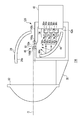
- FIG. 1 is a cross-sectional view illustrating a configuration of a vehicular lamp 10 according to the first embodiment.
- the vehicular lamp 10 is used as a vehicle headlamp.
- the vehicular lamp 10 is disposed on each of the left and right sides of the front portion of the vehicle body.
- the vehicle lamp 10 positioned on the right side when viewed from the front of the vehicle body will be described.
- the left vehicular lamp 10 basically has the same configuration.
- the vehicle lamp 10 includes a lamp body 12, a translucent cover 14, a lamp unit 16, and an extension reflector 18.
- the lamp body 12 is formed in a box shape having an opening.
- the translucent cover 14 is formed in a bowl shape with resin or glass having translucency. The translucent cover 14 is attached to the lamp body 12 so as to cover the opening of the lamp body 12.
- the lamp unit 16 is disposed in a lamp chamber 20 formed by the lamp body 12 and the translucent cover 14.
- the lamp unit 16 is a so-called projector type optical unit.
- the lamp unit 16 is attached to substantially the center of the metal support member 22 arranged so that the main surface faces the lamp front-rear direction.
- the metal support member 22 is tiltably supported by the lamp body 12 by the aiming screw 24. When the aiming screw 24 rotates, the metal support member 22 tilts, and the lamp unit 16 tilts accordingly. Thereby, the optical axis of the lamp unit 16 can be adjusted in the horizontal direction and the vertical direction.
- the extension reflector 18 is arranged in the lamp chamber 20 similarly to the lamp body 12.
- the extension reflector 18 is disposed so as to cover a region between the opening of the lamp body 12 and the outer periphery of the lamp unit 16. Thereby, the internal structure of the vehicular lamp 10 can be hidden.
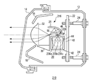
- FIG. 2 is a cross-sectional view showing the lamp unit 16 of FIG.
- the lamp unit 16 includes a light source module 26, a reflector 28, a lens holder 30, and a projection lens 32.
- the reflector 28 is a substantially dome-shaped member, and is disposed above the light source module 26. In particular, the reflector 28 is disposed so as to face an emission surface 50a of a phosphor 50 (described later).
- the reflector 28 has a reflection surface 28a on the inner side based on a spheroid.
- the reflective surface 28a has a first focal point and a second focal point located on the front side of the lamp relative to the first focal point.
- the reflector 28 has a positional relationship with the phosphor 50 so that the first focal point of the reflecting surface 28 a substantially coincides with the phosphor 50.
- the lens holder 30 is a member extending in the front-rear direction.
- the rear side of the lens holder 30 is fixed to the light source module 26.
- a projection lens 32 is fixed to the front side of the lens holder 30.
- the projection lens 32 is a plano-convex aspheric lens having a convex front surface and a flat rear surface.
- the projection lens 32 projects the light source image formed on the rear focal plane including the rear focus on the virtual vertical screen in front of the lamp as a reverse image.
- the light source module 26 includes a light source unit 34, a heat sink 42, a condensing reflector 44, a phosphor module 46, and a case 48.
- the case 48 is formed in a box shape. A light source unit 34 and a light collecting reflector 44 are accommodated in the case 48.
- the light source unit 34 includes a first light source unit 34a, a second light source unit 34b, and a third light source unit 34c.
- the first light source unit 34a includes a first light source 36a, a first substrate 38a, and a first lens 40a.
- the first light source 36a is a laser diode that emits blue laser light.
- the first light source 36a is a laser diode having a peak wavelength in the wavelength range of 380 to 470 nm.
- the first light source 36a may be a laser device such as a solid-state laser or a gas laser.
- the first substrate 38 a is attached to the front surface 42 a of the heat sink 42.
- the first light source 36a is mounted on the first substrate 38a so that the laser emission surface faces the front of the lamp.
- the first lens 40 a is provided between the first light source 36 a and the condensing reflector 44.
- the first lens 40a converts the laser light traveling from the first light source 36a toward the condensing reflector 44 into parallel light.
- the first lens 40a may have a function of adjusting the tilt angle in the vertical direction. In this case, the tilt error due to the dimensional error of the first substrate 38a can be corrected.
- the second light source unit 34b includes a second light source 36b, a second substrate 38b, and a second lens 40b.
- the third light source unit 34c includes a third light source 36c, a third substrate 38c, and a third lens 40c.
- the second light source 36b and the third light source 36c have the same configuration as the first light source 36a.
- the second substrate 38b and the third substrate 38c have the same configuration as the first substrate 38a.
- the second lens 40b and the third lens 40c have the same configuration as the first lens 40a.
- the 2nd lens 40b and the 3rd lens 40c may have a function which can adjust the inclination angle of an up-down direction.
- the heat sink 42 is formed of a material having high thermal conductivity such as aluminum.
- the front surface 42a of the heat sink 42 has a flat shape.
- a first substrate 38a on which the first light source 36a is mounted, a second substrate 38b on which the second light source 36b is mounted, and a third substrate 38c on which the third light source 36c is mounted are attached to the front surface 42a.
- the first substrate 38a, the second substrate 38b, and the third substrate 38c are arranged so that their rear surfaces are on the same plane, so that the front surface 42a of the heat sink 42 is made flat. Can do.
- the heat sink 42 is provided such that the front surface 42 a side slightly enters the case 48 from a through hole 48 b formed in the back surface 48 a of the case 48, and the remaining portion protrudes outside the case 48. Thereby, the heat generated by each light source can be dissipated outside the case 48, and the temperature rise of the light source and the light source module 26 can be suppressed.
- the condensing reflector 44 is provided in front of the light source unit 34.
- the condensing reflector 44 has a reflecting surface 44a.
- the reflecting surface 44a has a shape based on a paraboloid of revolution having an axis Ax passing through the phosphor 50 as a central axis.
- the light source unit 34 is arranged so that the laser light from the light source unit 34 is incident on the reflecting surface 44a substantially parallel to the axis Ax.
- the phosphor 50 is disposed so as to coincide with the focal point of the reflecting surface 44a. Specifically, the phosphor 50 is arranged so that the center thereof substantially coincides with the focal point of the reflecting surface 44a.
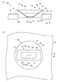
- FIG. 3 (a) and 3 (b) are diagrams showing the phosphor module 46 and its vicinity.
- FIG. 3A is a cross-sectional view taken along line AA in FIG.
- FIG.3 (b) is the figure which looked at Fig.3 (a) from the top.
- the phosphor module 46 includes a phosphor 50, a wavelength selection filter 52, and a holding member 53.
- the holding member 53 is formed from various metal materials.
- the holding member 53 is made of iron, SUS, brass (brass), molybdenum, tungsten, or an alloy thereof.
- the holding member 53 includes an upper part 53a and a lower part 53b each having a cylindrical outer peripheral surface.
- the outer peripheral surface of the lower part 53b has a smaller outer diameter than the outer peripheral surface of the upper part 53a.
- a through hole 48d having a diameter larger than the outer diameter of the lower portion 53b (for example, a diameter larger by several millimeters) is formed in the upper surface 48c of the case 48.
- the holding member 53 is fixed to the case 48 with the lower side portion 53 b entering the through hole 48 d and the lower surface of the upper portion 53 a placed on the upper surface 48 c of the case 48. Specifically, the holding member 53 is adjusted in the horizontal position with the lower portion 53b entering the through hole 48d, and is fixed to the case 48 by resistance welding, laser welding, arc welding, soldering, or caulking.
- a through hole 58 that communicates the upper surface 53c of the upper portion 53a and the lower surface 53d of the lower portion 53b is formed in the approximate center of the holding member 53.
- the through hole 58 is formed so that its cross-sectional area increases as it goes upward. Therefore, the inner wall 58a of the through hole 58 is inclined.
- the through hole 58 is formed such that the shape of the inner wall 58a in the vertical cross section is a straight line.
- the through-hole 58 is formed so that its cross-sectional shape becomes longer as it goes upward.
- the through-hole 58 is formed so that the ratio between the dimension in the short direction and the dimension in the long direction in the cross section increases as it goes upward.
- the opening 58b on the lower surface 53d side of the through hole 58 has a substantially circular shape.
- the opening 58c on the upper surface 53c side of the through hole 58 has a substantially oval shape. Therefore, the outer periphery of the opening 58c includes a pair of linear sides 58d and 58e extending in the longitudinal direction of the opening 58c.
- the shape of the through hole 58 in the cross section passing through the emission surface 50a also has a substantially oval shape.
- the through hole 58 is formed such that the dimension D1 in the longitudinal direction at the opening 58c on the upper surface 53c side is twice to four times the dimension D2 in the short direction. That is, the opening 58c is formed so that the ratio of the short direction to the long direction is 1: 2 to 1: 4.
- the phosphor 50 absorbs part of the blue laser light from the light source unit 34 and emits yellow light to Lambertian. The remaining laser light is emitted from the phosphor 50 without being absorbed by the phosphor 50. Since the structure of the phosphor 50 is known, a detailed description is omitted. The yellow light emitted from the phosphor 50 and the blue laser light emitted without being absorbed are mixed to generate white light. White light travels toward the reflector 28.
- the phosphor 50 has a shape corresponding to the shape of the through hole 58 of the holding member 53.
- the through hole 58 of the holding member 53 has a shape corresponding to the shape of the phosphor 50.
- the phosphor 50 is formed so that its cross-sectional area increases as it goes upward.
- the fluorescent substance 50 is formed so that the cross-sectional shape becomes longer as it goes upward.
- the phosphor 50 is formed such that the ratio between the dimension in the short direction and the dimension in the long direction in the cross section increases as it goes upward.
- the emission surface 50a of the phosphor 50 has a substantially oval shape. Therefore, the outer periphery of the emission surface 50a includes a pair of linear sides 50c and 50d extending in the longitudinal direction. The sides 50c and 50d particularly extend in the same direction as the sides 58d and 58e of the opening 58c.
- the phosphor 50 is formed such that the dimension D3 in the longitudinal direction on the emission surface 50a is twice to four times the dimension D4 in the short direction. That is, the phosphor 50 is formed so that the ratio of the short direction to the long direction of the emission surface 50a is 1: 2 to 1: 4.
- the wavelength selection filter 52 is provided below the phosphor 50, that is, between the phosphor 50 and the light source unit 34.
- the wavelength selection filter 52 transmits the blue laser light from the light source unit 34. Further, the wavelength selection filter 52 reflects light traveling downward among the yellow light emitted from the phosphor 50. Thereby, the utilization efficiency of the light from the fluorescent substance 50 can be improved.
- the wavelength selection filter 52 is a dielectric multilayer film formed on the lower surface of the phosphor 50 by vapor deposition.
- the dielectric multilayer film is a thin film in which dielectric materials having different refractive indexes are alternately laminated in multiple layers. Due to the effects of multiple reflection and multiple interference, it transmits almost 100% of blue light having a wavelength of 380 to 470 nm, and has a wavelength of 471 to 471. Reflects approximately 100% of light at 800 nm. Note that the reflectance of light having a wavelength of 471 to 800 nm by the dielectric multilayer film may not be approximately 100%. For example, it may be approximately 50%, approximately 80%, or other reflectance.
- the phosphor 50 and the wavelength selection filter 52 are inserted into the through hole 58 so that the side surfaces thereof are in contact with the inner wall 58a of the through hole 58, and are fixed by press-fitting or adhesion.
- the phosphor 50 and the wavelength selection filter 52 may be fixed by being sealed with a transparent member such as glass.
- a reflective film 54 is provided on the inner wall 58 a of the through hole 58. Therefore, the inner wall 58a of the through hole 58 functions as a reflecting surface. At least a part of the light directed downward in the Lambertian light in the phosphor 50 is reflected by the reflective film 54 and travels upward, that is, toward the reflector 28. Thereby, the utilization efficiency of the light from the fluorescent substance 50 can be improved.
- the inner wall 58a of the through hole 58 protrudes above the phosphor 50. That is, the annular reflecting surface protrudes above the phosphor 50. With the reflecting surface protruding upward, the light emitted from the phosphor 50 to Lambertian can be given directivity.
- the protruding annular reflecting surface is formed such that the dimension D5 in the vertical direction is 1.2 to 1.8 times the dimension D6 in the vertical direction of the phosphor 50. More preferably, it is formed to be 1.4 to 1.6 times.
- FIG. 4 is an explanatory diagram for explaining these relationships.
- the beam pattern P1 indicates the cross-sectional shape of the laser light on the opening 58b of the through hole 58.
- the beam pattern P2 indicates the cross-sectional shape of the laser light on the incident surface 50b of the phosphor 50.
- the beam pattern P3 indicates the cross-sectional shape of the laser light on the emission surface 50a of the phosphor 50.
- the laser beam has a long cross section, and spreads away from the light source. In FIG. 4, the thickness and the extent of spread of the laser beam are exaggerated.
- the opening 58b of the through hole 58 is larger than the beam pattern P1 of the laser beam.
- the diameter of the opening 58b is larger than the dimension in the longitudinal direction of the beam pattern P1 of the laser light.
- the diameter of the opening 58b may be substantially the same as the dimension in the longitudinal direction of the beam pattern P1 of the laser beam.
- the incident surface 50b of the phosphor 50 is larger than the beam pattern P2 of the laser beam.
- the longitudinal dimension of the incident surface 50b is larger than the longitudinal dimension of the laser beam pattern P2.
- the dimension in the longitudinal direction of the incident surface 50b may be substantially the same as the beam pattern P2 of the laser light.
- the case 48 is configured such that the upper surface 48c thereof includes the optical axis O and the ridge line 48f formed by the upper surface 48c and the front surface 48e is positioned in the vicinity of the second focal point of the reflector 28.
- the light reflected by the reflector 28 enters the projection lens 32 through the second focal point of the reflector 28, that is, the vicinity of the ridge line 48f.
- a reflective film 56 is provided on the upper surface 48 c of the case 48 (see FIG. 3), and a part of the light reflected by the reflector 28 is reflected by the reflective film 56. Therefore, the light from the reflector 28 is cut with the ridge line 48f as a boundary line. Thereby, the light distribution pattern which has the cut-off line corresponding to the shape of the ridgeline 48f is projected ahead of the vehicle. That is, part of the case 48 functions as a shade.
- the first light source 36a, the second light source 36b, and the third light source 36c emit laser light.
- Each laser beam is converted into parallel light by the first lens 40 a, the second lens 40 b, and the third lens 40 c and enters the reflecting surface 44 a of the condensing reflector 44.
- the laser light incident on the condensing reflector 44 is reflected toward the approximate center of the phosphor 50.
- the phosphor 50 absorbs a part of the incident laser light and emits yellow light. The remaining laser light is emitted from the phosphor 50 without being absorbed by the phosphor 50.
- the yellow light and the blue light of the laser light are mixed to generate white light and travel toward the reflector 28.
- the reflecting surface 28 a of the reflector 28 reflects white light toward the projection lens 32.
- the projection lens 32 irradiates the light from the reflector 28 in front of the lamp as substantially parallel light.
- the emission surface 50a of the phosphor 50 has a long shape.
- the phosphor 50 includes a pair of straight sides 50c and 50d extending in the longitudinal direction on the outer periphery of the emission surface 50a. For this reason, when the light source module 26 is used as a light source of the vehicular lamp 10, it becomes easy to form a cut-off line. That is, the light source module suitable for the light source of the vehicular lamp can be realized.
- the phosphor 50 is formed so that the ratio of the short direction D4 and the long direction D3 on the emission surface 50a is 1: 2 to 1: 4.
- the upper opening 58c of the through hole 58 is formed so that the ratio of the short direction D2 to the long direction D1 is 1: 2 to 1: 4. That is, the light source module 26 having an aspect ratio suitable for the light source of the vehicular lamp can be realized.
- the phosphor D so that the dimension D 5 in the vertical direction of the reflecting surface protruding above the phosphor 50 is 1.2 to 1.8 times the dimension D 6 in the vertical direction of the phosphor 50.
- a module 46 is formed. More preferably, it is formed to be 1.4 to 1.6 times. Thereby, a light source module having a desired size and a desired luminance can be realized.
- the phosphor 50 is formed such that its cross-sectional area increases as it goes upward.
- the through hole 58 of the holding member 53 has a shape corresponding to the shape of the phosphor 50 and is formed so that its cross-sectional area increases as it goes upward. That is, the through hole 58 of the holding member 53 is formed so that the phosphor 50 cannot pass through. Since the phosphor 50 is held by the through hole 58 formed in this way, it is possible to prevent the phosphor 50 from dropping from the holding member 53.
- the laser light from the plurality of light source units 34 is condensed on the phosphor 50 by the reflection surface 44 a of the condensing reflector 44. Therefore, there is no loss at the time of incidence, light guidance, and emission, for example, when condensing with a light guide such as an optical fiber, so that the utilization efficiency of laser light is improved.
- the light source module 26 can be reduced in size compared to the case where light is collected by a light guide such as an optical fiber, which can contribute to the reduction in size of the vehicular lamp 10 on which the light source module 26 is mounted.
- the laser light from the plurality of light source units 34 is condensed on the phosphor 50 by the reflection surface 44a based on the paraboloid of revolution. Therefore, if the laser light from the light source unit 34 is incident on the reflecting surface 44a substantially parallel to the axis Ax that is the central axis of the reflecting surface 44a, the laser light is focused on the phosphor 50. That is, if the laser beam from the light source unit 34 is substantially parallel to the axis Ax, the distance between each member constituting the light source unit 34 and the axis Ax and the distance between each member and the reflecting surface 44a are not questioned. . Therefore, the position adjustment of the light source unit 34 is relatively easy.
- the first light source 36a, the second light source 36b, and the third light source 36c are accommodated in the case 48. For this reason, even if these light sources are removed, the laser light is prevented from being directly emitted to the outside of the light source module 26 and, consequently, directly emitted to the outside of the vehicle lamp 10 on which the light source module 26 is mounted.
- the first substrate 38a, the second substrate 38b, and the third substrate 38c are arranged so that the surfaces on the heat sink 42 side are located on the same plane, so that the front surface 42a of the heat sink 42 is flat. Can be made into any shape. For this reason, the heat sink 42 can be made into a single member and a relatively simple shape, and the number of heat sinks 42 and the processing cost can be reduced.
- FIG. 5 is a cross-sectional view showing the lamp unit 116 of the vehicular lamp according to the second embodiment.
- FIG. 5 corresponds to FIG.
- the lamp unit 116 includes a light source module 126, a reflector 28, a lens holder 30, and a projection lens 32.
- the light source module 126 includes a light source unit 34, a heat sink 42, a condensing reflector 44, a phosphor module 46, and a case 148.
- Case 148 is formed in a box shape. The case 148 houses the light source unit 34 and the condensing reflector 44.
- the upper surface 148c of the case 148 has an inclined portion 148g inclined backward.
- a through hole 148d is formed in the inclined portion 148g.
- the phosphor module 46 is fixed to the through hole 148d in the same manner as in the first embodiment.
- the phosphor module 46 is fixed so that the emission surface 50 a of the phosphor 50 is inclined backward with respect to the central axis of the reflection surface 28 a of the reflector 28.
- the central axis of the reflecting surface 28a substantially coincides with the optical axis O.
- the same effects as the effects obtained by the light source module 126 according to the second embodiment and the light source module 26 according to the first embodiment are exhibited.
- played by the vehicle lamp 10 which concerns on 1st Embodiment is show
- the emission surface 50a of the phosphor 50 is fixed so as to incline backward with respect to the central axis of the reflection surface 28a of the reflector 28. Thereby, the utilization solid angle of the reflective surface 28a of the reflector 28 can be increased.
- FIG. 6 is a cross-sectional view showing a vehicular lamp 210 according to the third embodiment.
- FIG. 6 corresponds to FIG.
- the vehicular lamp 210 includes the lamp body 12, the translucent cover 14, the lamp unit 216, and the extension reflector 18.
- the lamp unit 216 includes a light source module 226, a reflector 28, a lens holder 30, and a projection lens 32.
- the first light source 236a, the second light source 236b, and the third light source 236c of the light source module 226 are arranged in the front-rear direction, and their laser emission ports are on the lamp body 12 side (left-right direction in FIG. 6). It is arranged to face.
- the same operational effects as the operational effects exhibited by the light source module 26 according to the first embodiment are exhibited.
- the emission ports of the respective light sources are arranged so as to face the lamp body 12 side. Thereby, even if the case 48 and the condensing reflector 44 are removed, the laser light from each light source is prevented from being directly emitted to the outside of the lamp.
- FIG. 7 is a cross-sectional view showing a lamp unit 316 of a vehicle lamp according to the fourth embodiment.
- FIG. 7 corresponds to FIG.
- the lamp unit 316 includes a light source module 326, a reflector 28, a lens holder 30, and a projection lens 32.
- the light source module 326 includes a light source unit 334, a heat sink 42, a condenser lens 344, a phosphor module 46, and a case 48.
- the case 48 houses a light source unit 334 and a condenser lens 344.
- the light source unit 334 includes a light source 336 and a substrate 338. The light source 336 and the substrate 338 correspond to the first light source 36a and the first substrate 38a of the first embodiment, respectively.
- the condenser lens 344 is provided between the light source 336 and the phosphor 50. Laser light emitted from the light source 336 is condensed by the condenser lens 344 and enters the phosphor 50.
- the vehicular lamp 10 may include a lens that converts laser light emitted from the light source 336 into parallel light instead of the condenser lens 344.
- the same operational effects as the operational effects exhibited by the light source module 26 according to the first embodiment are exhibited.
- the effect similar to the effect shown by the vehicle lamp 10 which concerns on 1st Embodiment is show
- the light source module 26 includes the three light source units of the first light source unit 34a, the second light source unit 34b, and the third light source unit 34c has been described.
- the present invention is not limited to this.
- the light source module 26 may include two, or four or more light source units.
- the light source units are arranged in the vertical direction, and in the third embodiment, the light source units are arranged in the front-rear direction.
- the present invention is not limited to this.
- the light source units may be arranged in the left-right direction (the paper surface direction in FIG. 2).
- four or more light source units may be arranged in a matrix.
- five or more light source units may be arranged in a cross shape.
- each light source unit may be arranged irregularly. That is, the laser beams from the plurality of light source units may be arranged so as to enter the reflecting surface 44a substantially parallel to the axis Ax.
- the light source unit emits blue laser light
- the phosphor 50 absorbs the blue laser light and emits yellow light
- the yellow light and the blue laser light are
- the light source unit may emit ultraviolet laser light
- the phosphor may be configured to absorb ultraviolet laser light and emit blue light and yellow light. In this case, blue light emitted from the phosphor and yellow light are mixed to generate white light.
- the light source unit may emit an ultraviolet laser beam
- the phosphor may absorb the ultraviolet laser beam and emit red light, green light, and blue light.
- red light, green light, and blue light emitted from the phosphor are mixed to generate white light.
- At least one of the plurality of light source units is provided such that the laser light from the light source unit is incident on the emission surface 50a of the phosphor 50 substantially at right angles. Also good. In this case, the emission loss at the emission surface 50a of the phosphor 50 is suppressed, and the light utilization efficiency is improved.
- the lamp unit is a so-called projector-type optical unit.
- the present invention is not limited to this.
- the lamp unit may be a so-called parabolic optical unit.
- FIG. 8 is a cross-sectional view showing a lamp unit 416 of a vehicle lamp according to a modification.
- the lamp unit 416 includes a so-called parabolic light source module 26 and a reflector 428.
- the reflector 428 is a substantially dome-shaped member and is disposed above the light source module 26.
- the reflector 428 has a reflection surface 428a on the inner side based on a paraboloid of revolution.
- the positional relationship between the reflector 428 and the phosphor 50 is determined so that the focal point of the reflecting surface 428 a coincides with the phosphor 50.
- the reflector 428 irradiates light from the light source module 26 in front of the lamp.
- FIGS. 9A and 9B show a phosphor module 546 of a light source module according to a modification.
- FIGS. 9A and 9B correspond to FIGS. 3A and 3B.
- the opening 58b may be formed in a long shape.
- the opening 58b may be formed in a shape substantially the same as the cross-sectional shape of the laser light on the opening 58b, or a shape substantially similar to the cross-sectional shape of the laser light on the opening 58b.
- the incident surface 50b has substantially the same cross-sectional shape as the laser beam on the incident surface 50b or the laser beam on the incident surface 50b. It may be formed in a shape substantially similar to the cross-sectional shape.
- the emission surface 50a of the phosphor 50 has an oval shape.
- the present invention is not limited to this.
- the emission surface 50a may have, for example, a substantially rectangular shape. That is, the emission surface 50a only needs to have a long shape and include a pair of straight sides whose outer periphery extends in the long direction.
- the opening 58c of the through hole 58 has an oval shape, but the present invention is not limited to this.
- the opening 58c may have a substantially rectangular shape, for example. That is, the opening 58c only needs to have a long shape and include a pair of straight sides whose outer periphery extends in the long direction.
- FIGS. 10A and 10B show a phosphor module 646 of a light source module according to a modification.
- FIGS. 10A and 10B correspond to FIGS. 3A and 3B.
- the phosphor 50 is formed integrally with the holding member 53.
- the phosphor 50 is formed by using the holding member 53 as a mold. Specifically, the opening 58b on the lower surface 53d side of the holding member 53 is closed, a resin or ceramic containing a fluorescent material is injected into the through hole 58 in which the opening 58b is closed, and the holding member 53 is sintered together. A phosphor 50 is formed.
- the metal mesh 660 is coupled to the inner wall 58a of the holding member 53, the mesh 660 and the phosphor 50 are integrated by forming the phosphor 50 as described above.
- the same operational effects as the operational effects exhibited by the light source modules according to the first to fourth embodiments are exhibited.
- the phosphor 50 is sintered and formed in a state where a resin or ceramic containing a fluorescent material is injected into the through hole 58 of the holding member 53. Therefore, the process of assembling the phosphor 50 to the holding member 53 becomes unnecessary.
- the phosphor 50 is integrated with the mesh 660 coupled to the holding member 53. Therefore, dropping off of the phosphor 50 is suppressed.
- the phosphor 50 is integrated with a metal mesh 660 coupled to the holding member 53. Therefore, the heat generated in the phosphor 50 is transmitted to the holding member 53 through the mesh 660 and is radiated. That is, according to this modification, the heat dissipation performance of the phosphor 50 can be enhanced, and a decrease in the light emission efficiency (laser light conversion efficiency) of the phosphor 50 due to heat generation can be suppressed. As a result, the brightness of the phosphor 50 can be increased, and the phosphor 50 can be suitably used as a light source for a vehicular lamp.
- the protrusion of the phosphor 50 can be suppressed by the protrusion, and the heat dissipation performance of the phosphor 50 can be improved by the protrusion.
- the present invention can be used for a light source module and a vehicular lamp provided with the light source module.
Landscapes
- Engineering & Computer Science (AREA)
- General Engineering & Computer Science (AREA)
- Physics & Mathematics (AREA)
- Optics & Photonics (AREA)
- Non-Portable Lighting Devices Or Systems Thereof (AREA)
- Mechanical Engineering (AREA)
Abstract
本発明の車両用灯具は、レーザ光を出射する第1光源(36a)、第2光源(36b)および第3光源(36c)と、それらから出射されたレーザ光のそれぞれを平行にするための第1レンズ(40a)、第2レンズ(40b)および第3レンズ(40c)と、それらを透過したレーザ光のそれぞれを反射する回転放物面形状を基調とする反射面(44a)を有する集光リフレクタ(44)と、集光リフレクタ(44)により反射されたレーザ光を受けて発光する蛍光体(50)と、を備える。
Description
本発明は光源モジュールおよびそれを備える車両用灯具に関する。
近年、レーザ光を出射するレーザ光源とレーザ光を受けて発光する蛍光体とを備える光源モジュールおよびそれを備える車両用灯具の開発が進んでいる。この光源モジュールでは、レーザ光源から出射されたレーザ光が蛍光体に照射される。蛍光体は、レーザ光を受けて光を発する。蛍光体が発した光が混色され、あるいは蛍光体が発した光とレーザ光とが混色されて白色光が生成される。白色光は灯具前方に照射され、所定の配光パターンを形成する。従来では、例えば特許文献1、2に記載されるような光源モジュールおよび車両用灯具が提案されている。
レーザ光源は、一般に、輝度は高いものの光束は低いため、車両用灯具として求められる光束を実現するためには、複数のレーザ光源を用い、それら複数のレーザ光源からのレーザ光を集光して蛍光体に照射する必要がある。
複数のレーザ光源からのレーザ光を集光する手法として、導光体により集光することがある。しかしながら、導光体により集光する場合、導光体への入射時、導光時、そして導光体からの出射時にレーザ光のロスが生じうる。
また、従来より、カットオフラインを有する配光パターンを形成するように構成された車両用灯具が知られている。特許文献2に記載されるような従来の光源モジュールは、このような車両用灯具の光源としては改善の余地がある。
本発明はこうした状況に鑑みてなされたものであり、その目的の1つは、レーザ光源からのレーザ光を効率的に利用できる技術を提供することにある。
また、本発明の他の目的の1つは、車両用灯具の光源として適した光源モジュールを提供することにある。
上記課題を解決するために、本発明のある態様の車両用灯具は、レーザ光を出射する複数の光源と、複数の光源から出射されたレーザ光のそれぞれを平行にするための透過部材と、透過部材を透過したレーザ光のそれぞれを反射する回転放物面を基調とする反射面を有する第1光学部材と、第1光学部材により反射されたレーザ光を受けて発光する発光部材と、発光部材からの光を灯具前方に照射する第2光学部材と、を備える。
回転放物面を基調とする反射面により、複数の光源から出射されたレーザ光が発光部材に集光される。これにより、レーザ光を効率的に利用することができる。
本発明の別の態様は、光源モジュールである。この光源モジュールは、レーザ光を出射する複数の光源と、複数の光源から出射されたレーザ光のそれぞれを平行にするための透過部材と、透過部材を透過したレーザ光のそれぞれを反射する回転放物面を基調とする反射面を有する光学部材と、光学部材により反射されたレーザ光を受けて発光する発光部材と、を備える。
回転放物面を基調とする反射面により、複数の光源から出射されたレーザ光が発光部材に集光される。これにより、レーザ光を効率的に利用することができる。
本発明のさらに別の態様も光源モジュールである。この光源モジュールは、レーザ光を出射する光源と、光源からのレーザ光を受けて発光する蛍光体と、蛍光体を保持する保持部材と、を備える。保持部材は、傾斜壁面を有する貫通孔を有する。蛍光体は、その側面が貫通孔の傾斜壁面に接するように配置され、蛍光体の出射面は長尺状であり、その外周辺は長尺方向に延びる一対の直線状の辺を含む。
この態様によると、蛍光体の出射面の外周辺は、その長尺方向に延びる一対の直線状の辺を含む。このため、光源モジュールを車両用灯具の光源に使用した場合、カットオフラインを形成するのが容易となる。
なお、以上の構成要素の任意の組み合わせや、本発明の構成要素や表現を装置、方法、システムなどの間で相互に置換したものもまた、本発明の態様として有効である。
本発明によれば、レーザ光源からのレーザ光を効率的に利用できる。
また、本発明によれば、車両用灯具の光源として使用するのに適した光源モジュールを提供できる。
以下、各図面に示される同一または同等の構成要素、部材には、同一の符号を付するものとし、適宜重複した説明は省略する。また、各図面における部材の寸法は、理解を容易にするために適宜拡大、縮小して示される。また、各図面において実施の形態を説明する上で重要ではない部材の一部は省略して表示する。
(第1の実施の形態)
図1は、第1の実施形態に係る車両用灯具10の構成を示す断面図である。車両用灯具10は車両の前照灯として用いられる。車両用灯具10は車体前部の左右両側にそれぞれ配置される。本実施の形態では車体前方から見て右側に位置する車両用灯具10について説明する。左側の車両用灯具10も基本的に同様の構成を有する。
図1は、第1の実施形態に係る車両用灯具10の構成を示す断面図である。車両用灯具10は車両の前照灯として用いられる。車両用灯具10は車体前部の左右両側にそれぞれ配置される。本実施の形態では車体前方から見て右側に位置する車両用灯具10について説明する。左側の車両用灯具10も基本的に同様の構成を有する。
車両用灯具10は、ランプボディ12、透光カバー14、灯具ユニット16、エクステンションリフレクタ18を備える。ランプボディ12は開口部を有する箱状に形成される。透光カバー14は、透光性を有する樹脂またはガラスによって椀状に形成される。透光カバー14は、ランプボディ12の開口部を覆うようにランプボディ12に取り付けられる。
灯具ユニット16は、ランプボディ12と透光カバー14とによって形成される灯室20内に配置される。灯具ユニット16は、いわゆるプロジェクタ型の光学ユニットである。灯具ユニット16は、主表面が灯具前後方向を向くよう配置された金属製支持部材22の略中央に取り付けられる。金属製支持部材22は、エイミングスクリュー24によってランプボディ12に傾動自在に支持される。エイミングスクリュー24が回転すると金属製支持部材22が傾動し、それに伴って灯具ユニット16が傾動する。これにより、灯具ユニット16の光軸を水平方向および鉛直方向に調整できる。
エクステンションリフレクタ18は、ランプボディ12と同様に灯室20内に配置される。エクステンションリフレクタ18は特に、ランプボディ12の開口部と灯具ユニット16の外周との間の領域を覆うように配置される。これにより、車両用灯具10の内部構造を隠すことができる。
図2は、図1の灯具ユニット16を示す断面図である。灯具ユニット16は、光源モジュール26、リフレクタ28、レンズホルダ30、投影レンズ32を備える。
リフレクタ28は、略ドーム状の部材であり、光源モジュール26の上方に配置される。リフレクタ28は特に、蛍光体50(後述)の出射面50aと対向するよう配置される。リフレクタ28は、回転楕円面を基調とした反射面28aを内側に有する。反射面28aは、第1焦点と、第1焦点よりも灯具前方側に位置する第2焦点とを有する。リフレクタ28は、反射面28aの第1焦点が蛍光体50と略一致するよう、蛍光体50との位置関係が定められている。
レンズホルダ30は前後方向に延在する部材である。レンズホルダ30は、その後方側が光源モジュール26に固定される。レンズホルダ30の前方側には投影レンズ32が固定される。投影レンズ32は、前方側表面が凸面で後方側表面が平面の平凸非球面レンズである。投影レンズ32は、その後方焦点を含む後方焦点面上に形成される光源像を、反転像として灯具前方の仮想鉛直スクリーン上に投影する。
光源モジュール26は、光源ユニット34、ヒートシンク42、集光リフレクタ44、蛍光体モジュール46、ケース48を備える。ケース48は箱状に形成される。ケース48内には光源ユニット34と集光リフレクタ44が収容される。
光源ユニット34は、第1光源ユニット34a、第2光源ユニット34b、第3光源ユニット34cを含む。第1光源ユニット34aは、第1光源36a、第1基板38a、第1レンズ40aを含む。第1光源36aは、青色のレーザ光を発するレーザダイオードである。本実施の形態では、第1光源36aは、380~470nmの波長域内にピーク波長を有するレーザダイオードである。第1光源36aは、固体レーザ、ガスレーザ等のレーザ装置であってもよい。
第1基板38aは、ヒートシンク42の前面42aに取り付けられる。第1光源36aは、レーザ出射面が灯具前方を向くよう、第1基板38aに搭載される。第1レンズ40aは、第1光源36aと集光リフレクタ44との間に設けられる。第1レンズ40aは、第1光源36aから集光リフレクタ44に向かうレーザ光を平行光に変換する。なお、第1レンズ40aは、上下方向の傾き角度を調整できる機能を有していてもよい。この場合、第1基板38aの寸法誤差等による傾き誤差を修正できる。
第2光源ユニット34bは、第2光源36bと、第2基板38bと、第2レンズ40bと、を含む。
第3光源ユニット34cは、第3光源36cと、第3基板38cと、第3レンズ40cと、を含む。
第2光源36b、第3光源36cはそれぞれ第1光源36aと同様の構成を有する。
第2基板38b、第3基板38cはそれぞれ第1基板38aと同様の構成を有する。
第2レンズ40b、第3レンズ40cはそれぞれ第1レンズ40aと同様の構成を有する。なお、第2レンズ40b、第3レンズ40cは、上下方向の傾き角度を調整できる機能を有していてもよい。
第3光源ユニット34cは、第3光源36cと、第3基板38cと、第3レンズ40cと、を含む。
第2光源36b、第3光源36cはそれぞれ第1光源36aと同様の構成を有する。
第2基板38b、第3基板38cはそれぞれ第1基板38aと同様の構成を有する。
第2レンズ40b、第3レンズ40cはそれぞれ第1レンズ40aと同様の構成を有する。なお、第2レンズ40b、第3レンズ40cは、上下方向の傾き角度を調整できる機能を有していてもよい。
ヒートシンク42は、アルミニウムなどの熱伝導率が高い材料によって形成される。ヒートシンク42の前面42aは平坦な形状を有する。この前面42aに、第1光源36aを搭載した第1基板38a、第2光源36bを搭載した第2基板38b、第3光源36cを搭載した第3基板38cが取り付けられる。逆に言うと、第1基板38a、第2基板38bおよび第3基板38cは、後方側の面が同一平面上に位置するよう配置されるため、ヒートシンク42の前面42aを平坦な形状にすることができる。
ヒートシンク42は、前面42a側がケース48の背面48aに形成された貫通孔48bからケース48内にわずかに進入し、残りの部分がケース48外に突出するよう設けられる。これにより、各光源で発生した熱をケース48外に放熱することができ、光源ひいては光源モジュール26の温度上昇が抑えられる。
集光リフレクタ44は光源ユニット34の前方に設けられる。集光リフレクタ44は反射面44aを有する。この反射面44aは、蛍光体50を通る軸Axを中心軸とする回転放物面を基調とする形状を有する。
光源ユニット34は、光源ユニット34からのレーザ光が軸Axと略平行に反射面44aに入射されるよう配置される。蛍光体50は、反射面44aの焦点と一致するよう配置される。具体的には、蛍光体50は、その中央が反射面44aの焦点と略一致するよう配置される。光源ユニット34、反射面44a、蛍光体50がこのように構成されることにより、複数の光源ユニット34からのレーザ光は蛍光体50に集光する。
図3(a)、(b)は、蛍光体モジュール46とその近傍を示す図である。図3(a)は、図2のA-A線断面図である。図3(b)は、図3(a)を上から見た図である。蛍光体モジュール46は、蛍光体50、波長選択フィルタ52、保持部材53を含む。
保持部材53は、種々の金属材料から形成される。例えば、保持部材53は、鉄、SUS、黄銅(真鍮)、モリブデン、タングステン、またはこれらの合金から形成される。保持部材53は、それぞれ円筒状の外周面を有する上側部53aと下側部53bとを含む。下側部53bの外周面は、上側部53aの外周面よりも小さな外径を有する。ケース48の上面48cには下側部53bの外径よりも大きい径(例えば数ミリ大きい径)の貫通孔48dが形成されている。保持部材53は、下側部53bが貫通孔48dに進入し、上側部53aの下面がケース48の上面48cに載置した状態でケース48に固定される。具体的には、保持部材53は、下側部53bが貫通孔48dに進入した状態で水平方向の位置が調整され、抵抗溶接、レーザ溶接、アーク溶接、半田、またはカシメによりケース48に固定される。
保持部材53の略中央には、上側部53aの上面53cと、下側部53bの下面53dと、を連通する貫通孔58が形成されている。貫通孔58は、上側となるほどその断面積が大きくなるよう形成されている。したがって、貫通孔58の内壁58aは傾斜している。本実施の形態では、貫通孔58は、垂直断面における内壁58aの形状が、直線状となるよう形成される。
貫通孔58は、上側となるほどその断面形状がより長尺な形状となるよう形成される。別の言い方をすると、貫通孔58は、上側となるほど、その断面における短尺方向の寸法と長尺方向方の寸法との比が大きくなるよう形成される。
貫通孔58の下面53d側の開口58bは略円形状を有する。一方、貫通孔58の上面53c側の開口58cは略長円上を有する。したがって、開口58cの外周辺は、開口58cの長尺方向に延びる一対の直線状の辺58d、58eを含む。また、後述するように蛍光体50の出射面50aは略長円形状を有するため、出射面50aを通る断面における貫通孔58の形状も略長円形状を有する。
また、貫通孔58は、上面53c側の開口58cにおける長尺方向の寸法D1が、短尺方向の寸法D2の2倍~4倍となるよう形成される。つまり、開口58cは、短尺方向と長尺方向との比が1:2~1:4となるよう形成される。
蛍光体50は、光源ユニット34からの青色のレーザ光の一部を吸収してランバーシアンに黄色の光を発光する。残りのレーザ光は、蛍光体50に吸収されることなく蛍光体50から出射される。蛍光体50の構造は公知であるため詳細な説明は省略する。蛍光体50が発光した黄色の光と、吸収されることなく出射された青色のレーザ光とが混色されて白色光が生成される。白色光はリフレクタ28に向けて進行する。
蛍光体50は、保持部材53の貫通孔58の形状に対応する形状を有する。逆に言うと、保持部材53の貫通孔58が、蛍光体50の形状に対応する形状を有する。具体的には、蛍光体50は、上側となるほどその断面積が大きくなるよう形成される。また、蛍光体50は、上側となるほどその断面形状がより長尺な形状となるよう形成される。別の言い方をすると、蛍光体50は、上側となるほど、その断面における短尺方向の寸法と長尺方向方の寸法との比が大きくなるよう形成される。
蛍光体50の出射面50aは略長円形状を有する。そのため、出射面50aの外周辺は、長尺方向に延びる一対の直線状の辺50c、50dを含む。辺50c、50dは特に、開口58cの辺58d、58eと同じ方向に延びる。また、蛍光体50は、出射面50aにおける長尺方向の寸法D3が、短尺方向の寸法D4の2倍~4倍となるよう形成される。つまり、蛍光体50は、出射面50aの短尺方向と長尺方向との比が1:2~1:4となるよう形成される。
波長選択フィルタ52は、蛍光体50の下方、すなわち蛍光体50と光源ユニット34の間に設けられる。波長選択フィルタ52は、光源ユニット34からの青色のレーザ光を透過する。また、波長選択フィルタ52は、蛍光体50が発光した黄色の光のうち、下方に向かう光を反射する。これにより、蛍光体50からの光の利用効率を高めることができる。
本実施の形態では、波長選択フィルタ52は、蛍光体50の下面に蒸着により形成された誘電体多層膜である。誘電体多層膜は、屈折率の異なる誘電体物質を交互に多層に積層した薄膜であり、多重反射と多重干渉の効果により、波長380~470nmの青色光を略100%透過し、波長471~800nmの光を略100%反射する。なお、誘電体多層膜による波長471~800nmの光の反射率は、略100%でなくてもよい。例えば略50%であっても、略80%であっても、その他の反射率であってもよい。
蛍光体50および波長選択フィルタ52は、側面が貫通孔58の内壁58aに接するように貫通孔58に挿入され、圧入や接着により固定される。蛍光体50および波長選択フィルタ52は、ガラス等の透明部材により封止されることによって固定されてもよい。
貫通孔58の内壁58aには反射膜54が設けられている。したがって、貫通孔58の内壁58aは反射面として機能する。蛍光体50においてランバーシアンに発光された光のうち下方に向かう光の少なくとも一部は、この反射膜54に反射されて上方すなわちリフレクタ28に向かう。これにより、蛍光体50からの光の利用効率を高めることができる。
貫通孔58の内壁58aは蛍光体50よりも上側に突出する。すなわち、環状の反射面が蛍光体50よりも上側に突出する。この上側に突出した反射面により、蛍光体50においてランバーシアンに発光した光に指向性を持たせることができる。この突出した環状の反射面は、その上下方向における寸法D5が、蛍光体50の上下方向における寸法D6の1.2~1.8倍となるよう形成される。より好ましくは、1.4~1.6倍となるよう形成される。
続いて、貫通孔58の開口58bの形状と、蛍光体50の入射面50bの形状と、蛍光体50の出射面50aの形状と、各光源から放射されるレーザ光の形状と、の関係について説明する。図4は、これらの関係を説明するための説明図である。図4では、蛍光体モジュール46を上から見た図が示される。ビームパターンP1は、貫通孔58の開口58b上でのレーザ光の断面形状を示す。ビームパターンP2は、蛍光体50の入射面50b上でのレーザ光の断面形状を示す。ビームパターンP3は、蛍光体50の出射面50a上でのレーザ光の断面形状を示す。図4に示すように、レーザ光は断面が長尺状であり、光源から離れるにつれて拡がっていく。なお図4では、レーザ光の厚みと拡がり度合とを誇張して描いている。
貫通孔58の開口58bは、レーザ光のビームパターンP1よりも大きい。別の言い方をすると、開口58bの直径は、レーザ光のビームパターンP1の長尺方向の寸法よりも大きい。なお、開口58bの直径は、レーザ光のビームパターンP1の長尺方向の寸法と略同一であってもよい。
蛍光体50の入射面50bは、レーザ光のビームパターンP2よりも大きい。別の言い方をすると、入射面50bの長尺方向の寸法は、レーザ光のビームパターンP2の長尺方向の寸法よりも大きい。なお、入射面50bの長尺方向の寸法は、レーザ光のビームパターンP2と略同一であってもよい。
図2に戻り、ケース48は、その上面48cが光軸Oを含み、その上面48cとその前面48eとがなす稜線48fがリフレクタ28の第2焦点近傍に位置するよう構成される。リフレクタ28で反射された光は、リフレクタ28の第2焦点、すなわち稜線48fの近傍を通って投影レンズ32に入射する。ケース48の上面48cには反射膜56が設けられており(図3参照)、リフレクタ28で反射された光の一部はこの反射膜56で反射される。そのため、稜線48fを境界線としてリフレクタ28からの光がカットされる。これにより、稜線48fの形状に対応するカットオフラインを有する配光パターンが車両前方に投影される。つまり、ケース48は、その一部がシェードとして機能する。
以上のように構成された車両用灯具10の動作を説明する。
車両用灯具10の点灯指示を受けると、第1光源36a、第2光源36b、第3光源36cは、レーザ光を出射する。各レーザ光は、第1レンズ40a、第2レンズ40b、第3レンズ40cで平行光に変換されて集光リフレクタ44の反射面44aに入射する。集光リフレクタ44に入射したレーザ光は、蛍光体50の略中央に向けて反射される。蛍光体50は、入射したレーザ光の一部を吸収して黄色の光を発する。残りのレーザ光は蛍光体50に吸収されることなく蛍光体50から出射される。この黄色の光とレーザ光の青色の光とが混色されて白色光が生成され、リフレクタ28に向けて進行する。リフレクタ28の反射面28aは、白色光を投影レンズ32に向けて反射する。投影レンズ32は、リフレクタ28からの光を略平行な光として灯具前方に照射する。
車両用灯具10の点灯指示を受けると、第1光源36a、第2光源36b、第3光源36cは、レーザ光を出射する。各レーザ光は、第1レンズ40a、第2レンズ40b、第3レンズ40cで平行光に変換されて集光リフレクタ44の反射面44aに入射する。集光リフレクタ44に入射したレーザ光は、蛍光体50の略中央に向けて反射される。蛍光体50は、入射したレーザ光の一部を吸収して黄色の光を発する。残りのレーザ光は蛍光体50に吸収されることなく蛍光体50から出射される。この黄色の光とレーザ光の青色の光とが混色されて白色光が生成され、リフレクタ28に向けて進行する。リフレクタ28の反射面28aは、白色光を投影レンズ32に向けて反射する。投影レンズ32は、リフレクタ28からの光を略平行な光として灯具前方に照射する。
第1の実施の形態に係る光源モジュール26によると、蛍光体50は、その出射面50aが長尺状の形状を有する。蛍光体50は特に、出射面50aの外周辺が、長尺方向に延びる一対の直線状の辺50c、50dを含む。このため、光源モジュール26を車両用灯具10の光源に使用した場合、カットオフラインを形成するのが容易となる。つまり、車両用灯具の光源に適した光源モジュールを実現できる。
また、光源モジュール26によると、蛍光体50は、出射面50aにおける短尺方向D4と長尺方向D3との比が1:2~1:4となるよう形成される。また、貫通孔58の上側の開口58cは、短尺方向D2と長尺方向D1との比が1:2~1:4となるよう形成される。つまり、車両用灯具の光源に適した縦横比を有する光源モジュール26を実現できる。
また、光源モジュール26によると、蛍光体50よりも上側に突出した反射面の上下方向における寸法D5が、蛍光体50の上下方向における寸法D6の1.2~1.8倍となるよう蛍光体モジュール46が形成される。より好ましくは、1.4~1.6倍となるよう形成される。これにより、所望の大きさで、かつ、所望の輝度の光源モジュールを実現できる。
また光源モジュール26によると、蛍光体50は、上側となるほどその断面積が大きくなるよう形成される。また、保持部材53の貫通孔58は、蛍光体50の形状に対応した形状であって、上側となるほどその断面積が大きくなるよう形成される。つまり、保持部材53の貫通孔58は、蛍光体50が通過できないように形成される。このように形成された貫通孔58により蛍光体50を保持するため、保持部材53からの蛍光体50の脱落を抑止できる。
また、光源モジュール26によると、複数の光源ユニット34からのレーザ光が、集光リフレクタ44の反射面44aによって蛍光体50に集光される。そのため、例えば光ファイバなどの導光体によって集光するときのような入射時、導光時、出射時のロスが発生しないため、レーザ光の利用効率が向上する。また、例えば光ファイバなどの導光体によって集光する場合に比べ、光源モジュール26を小型化することができ、これを搭載する車両用灯具10の小型化に貢献できる。
また、光源モジュール26によると、回転放物面を基調とする反射面44aにより、複数の光源ユニット34からのレーザ光が蛍光体50に集光される。そのため、光源ユニット34からのレーザ光を反射面44aの中心軸である軸Axと略平行に反射面44aに入射すれば、そのレーザ光は蛍光体50に集光される。つまり、光源ユニット34からのレーザ光が軸Axと略平行であれば、光源ユニット34を構成する各部材と軸Axとの距離、そして各部材と反射面44aとの距離はいずれも問われない。したがって、光源ユニット34の位置調整は比較的容易となる。
また、光源モジュール26によると、第1光源36a、第2光源36b、第3光源36cは、ケース48内に収容される。このため、これら光源が外れても、レーザ光が光源モジュール26外部に直接出射されること、ひいては光源モジュール26を搭載する車両用灯具10外部に直接出射されることが防止される。
また、光源モジュール26によると、第1基板38a、第2基板38b、第3基板38cは、ヒートシンク42側の面が同一平面上に位置するように配置されるため、ヒートシンク42の前面42aを平坦な形状にすることができる。このため、ヒートシンク42を単一の部材でかつ比較的単純な形状にすることができ、ヒートシンク42の数および加工コストを低減できる。
(第2の実施の形態)
第1の実施の形態に係る車両用灯具10と第2の実施の形態に係る車両用灯具との主な違いは光源モジュールの形状である。図5は、第2の実施の形態に係る車両用灯具の灯具ユニット116を示す断面図である。図5は図2に対応する。
第1の実施の形態に係る車両用灯具10と第2の実施の形態に係る車両用灯具との主な違いは光源モジュールの形状である。図5は、第2の実施の形態に係る車両用灯具の灯具ユニット116を示す断面図である。図5は図2に対応する。
灯具ユニット116は、光源モジュール126と、リフレクタ28と、レンズホルダ30と、投影レンズ32と、を備える。光源モジュール126は、光源ユニット34と、ヒートシンク42と、集光リフレクタ44と、蛍光体モジュール46と、ケース148と、を備える。ケース148は、箱状に形成される。ケース148には、光源ユニット34と、集光リフレクタ44が収容される。
ケース148の上面148cは、後方向きに傾斜する傾斜部148gを有する。この傾斜部148gには、貫通孔148dが形成されている。蛍光体モジュール46は、第1の実施の形態と同様にして、この貫通孔148dに固定される。蛍光体モジュール46は特に、蛍光体50の出射面50aがリフレクタ28の反射面28aの中心軸に対して後方向きに傾斜するよう固定される。なお、本実施の形態では、反射面28aの中心軸は、光軸Oと略一致する。
第2の実施の形態に係る光源モジュール126と、第1の実施の形態に係る光源モジュール26によって奏される作用効果と同様の作用効果が奏される。また、第2の実施の形態に係る車両用灯具によると、第1の実施の形態に係る車両用灯具10によって奏される作用効果と同様の作用効果が奏される。加えて、第2の実施の形態に係る車両用灯具によると、蛍光体50の出射面50aがリフレクタ28の反射面28aの中心軸に対して後方向きに傾斜するよう固定される。これにより、リフレクタ28の反射面28aの利用立体角を増大させることができる。
(第3の実施の形態)
第1の実施の形態に係る車両用灯具10と第3の実施の形態に係る車両用灯具との主な違いは灯具ユニットの構成である。図6は、第3の実施の形態に係る車両用灯具210を示す断面図である。図6は図1に対応する。
第1の実施の形態に係る車両用灯具10と第3の実施の形態に係る車両用灯具との主な違いは灯具ユニットの構成である。図6は、第3の実施の形態に係る車両用灯具210を示す断面図である。図6は図1に対応する。
車両用灯具210は、ランプボディ12と、透光カバー14と、灯具ユニット216と、エクステンションリフレクタ18と、を備える。灯具ユニット216は、光源モジュール226と、リフレクタ28と、レンズホルダ30と、投影レンズ32と、を備える。本実施の形態では、光源モジュール226の第1光源236a、第2光源236b、第3光源236cが前後方向に並び、かつ、それらのレーザ出射口が、ランプボディ12側(図6では左右方向)を向くよう配置されている。
第3の実施の形態に係る光源モジュール226によると、第1の実施の形態に係る光源モジュール26によって奏される作用効果と同様の作用効果が奏される。また、第3の実施の形態に係る車両用灯具210によると、第1の実施の形態に係る車両用灯具10によって奏される作用効果と同様の作用効果が奏される。加えて、第3の実施の形態に係る車両用灯具210によると、各光源の出射口がランプボディ12側を向くよう配置される。これにより、仮にケース48および集光リフレクタ44が外れても、各光源からのレーザ光が灯具外部に直接出射されることが防止される。
(第4の実施の形態)
第1の実施の形態に係る車両用灯具10と第4の実施の形態に係る車両用灯具との主な違いは光源モジュールの構成である。図7は、第4の実施の形態に係る車両用灯具の灯具ユニット316を示す断面図である。図7は図2に対応する。
第1の実施の形態に係る車両用灯具10と第4の実施の形態に係る車両用灯具との主な違いは光源モジュールの構成である。図7は、第4の実施の形態に係る車両用灯具の灯具ユニット316を示す断面図である。図7は図2に対応する。
灯具ユニット316は、光源モジュール326と、リフレクタ28と、レンズホルダ30と、投影レンズ32と、を備える。光源モジュール326は、光源ユニット334と、ヒートシンク42と、集光レンズ344と、蛍光体モジュール46と、ケース48と、を備える。ケース48には、光源ユニット334と、集光レンズ344が収容される。光源ユニット334は、光源336、基板338を含む。光源336、基板338はそれぞれ、第1の実施の形態の第1光源36a、第1基板38aに対応する。
集光レンズ344は光源336と蛍光体50との間に設けられる。光源336から出射されたレーザ光は、集光レンズ344により集光されて蛍光体50に入射する。なお、車両用灯具10は、集光レンズ344の代わりに、光源336から出射されたレーザ光を平行光に変換するレンズを備えてもよい。
第4の実施の形態に係る光源モジュール326によると、第1の実施の形態に係る光源モジュール26によって奏される作用効果と同様の作用効果が奏される。また、第4の実施の形態に係る車両用灯具によると、第1の実施の形態に係る車両用灯具10によって奏される作用効果と同様の作用効果が奏される。
以上、本発明を実施の形態をもとに説明した。この実施の形態は例示であり、それらの各構成要素や各処理プロセスの組合せにいろいろな変形例が可能なこと、またそうした変形例も本発明の範囲にあることは当業者に理解されるところである。
(変形例1)
第1~3の実施の形態では、光源モジュール26が、第1光源ユニット34a、第2光源ユニット34b、第3光源ユニット34cの3つの光源ユニットを備える場合について説明したが、これに限られない。光源モジュール26は、2つ、または4つ以上の光源ユニットを備えていてもよい。
第1~3の実施の形態では、光源モジュール26が、第1光源ユニット34a、第2光源ユニット34b、第3光源ユニット34cの3つの光源ユニットを備える場合について説明したが、これに限られない。光源モジュール26は、2つ、または4つ以上の光源ユニットを備えていてもよい。
(変形例2)
第1、2の実施の形態では光源ユニットが上下方向に並び、第3の実施の形態では光源ユニットが前後方向に並ぶ場合について説明したがこれに限られない。例えば、第1の実施の形態において、光源ユニットが左右方向(図2の紙面方向)に並んでもよい。また例えば、4つ以上の光源ユニットがマトリクス状に並べられてもよい。また例えば、5つ以上の光源ユニットが十字状に並べられてもよい。もちろん、各光源ユニットは不規則に並べられてもよい。つまり、複数の光源ユニットからのレーザ光が軸Axと略平行に反射面44aに入射されるよう配置されればよい。
第1、2の実施の形態では光源ユニットが上下方向に並び、第3の実施の形態では光源ユニットが前後方向に並ぶ場合について説明したがこれに限られない。例えば、第1の実施の形態において、光源ユニットが左右方向(図2の紙面方向)に並んでもよい。また例えば、4つ以上の光源ユニットがマトリクス状に並べられてもよい。また例えば、5つ以上の光源ユニットが十字状に並べられてもよい。もちろん、各光源ユニットは不規則に並べられてもよい。つまり、複数の光源ユニットからのレーザ光が軸Axと略平行に反射面44aに入射されるよう配置されればよい。
(変形例3)
第1~4の実施の形態では、光源ユニットが青色のレーザ光を出射し、蛍光体50が青色のレーザ光を吸収して黄色の光を発し、この黄色の光と青色のレーザ光とが混色されて白色光が生成される場合について説明したが、これに限られない。例えば、光源ユニットが紫外のレーザ光を出射し、蛍光体は紫外のレーザ光を吸収して青色の光と黄色の光とを発するように構成されてもよい。この場合、蛍光体が発する青色の光と黄色の光とが混色されて、白色光が生成される。
第1~4の実施の形態では、光源ユニットが青色のレーザ光を出射し、蛍光体50が青色のレーザ光を吸収して黄色の光を発し、この黄色の光と青色のレーザ光とが混色されて白色光が生成される場合について説明したが、これに限られない。例えば、光源ユニットが紫外のレーザ光を出射し、蛍光体は紫外のレーザ光を吸収して青色の光と黄色の光とを発するように構成されてもよい。この場合、蛍光体が発する青色の光と黄色の光とが混色されて、白色光が生成される。
また例えば、光源ユニットが紫外のレーザ光を出射し、蛍光体が紫外のレーザ光を吸収して赤色の光、緑色の光、青色の光を発するように構成されてもよい。この場合、蛍光体が発する赤色の光、緑色の光、青色の光が混色されて、白色光が生成される。
(変形例4)
第1~3の実施の形態では特に触れなかったが、複数の光源ユニットの少なくとも1つは、その光源ユニットからのレーザ光が蛍光体50の出射面50aに略直角に入射するよう設けられてもよい。この場合は、蛍光体50の出射面50aでの出射ロスが抑制され、光の利用効率が向上する。
第1~3の実施の形態では特に触れなかったが、複数の光源ユニットの少なくとも1つは、その光源ユニットからのレーザ光が蛍光体50の出射面50aに略直角に入射するよう設けられてもよい。この場合は、蛍光体50の出射面50aでの出射ロスが抑制され、光の利用効率が向上する。
(変形例5)
第1~4の実施の形態では、灯具ユニットが、いわゆるプロジェクタ型の光学ユニットである場合について説明したが、これに限られない。灯具ユニットは例えば、いわゆるパラボラ型の光学ユニットであってもよい。
第1~4の実施の形態では、灯具ユニットが、いわゆるプロジェクタ型の光学ユニットである場合について説明したが、これに限られない。灯具ユニットは例えば、いわゆるパラボラ型の光学ユニットであってもよい。
図8は、変形例に係る車両用灯具の灯具ユニット416を示す断面図である。図8は図2に対応する。灯具ユニット416は、いわゆるパラボラ型の光源モジュール26と、リフレクタ428と、を備える。リフレクタ428は、略ドーム状の部材であり、光源モジュール26の上方に配置される。リフレクタ428は、回転放物面を基調とした反射面428aを内側に有する。リフレクタ428は、反射面428aの焦点が蛍光体50と一致するように、蛍光体50との位置関係が定められている。リフレクタ428は、光源モジュール26からの光を灯具前方に照射する。
本変形例によれば、実施の形態に係る光源モジュール26によって奏される作用効果と同様の作用効果が奏される。
(変形例6)
図9(a)、(b)は、変形例に係る光源モジュールの蛍光体モジュール546を示す。図9(a)、(b)は、図3(a)、(b)に対応する。第1~4の実施の形態では、貫通孔58の下面53d側の開口58bが略円形である場合について説明したが、これに限られない。図9(b)に示すように、開口58bは長尺状に形成されてもよい。開口58bは特に、開口58b上でのレーザ光の断面形状と略同一の形状、または開口58b上でのレーザ光の断面形状と略相似の形状に形成されてもよい。
図9(a)、(b)は、変形例に係る光源モジュールの蛍光体モジュール546を示す。図9(a)、(b)は、図3(a)、(b)に対応する。第1~4の実施の形態では、貫通孔58の下面53d側の開口58bが略円形である場合について説明したが、これに限られない。図9(b)に示すように、開口58bは長尺状に形成されてもよい。開口58bは特に、開口58b上でのレーザ光の断面形状と略同一の形状、または開口58b上でのレーザ光の断面形状と略相似の形状に形成されてもよい。
また、第1~第4の実施の形態では特に言及しなかったが、入射面50bは、入射面50b上でのレーザ光の断面形状と略同一の形状または入射面50b上でのレーザ光の断面形状と略相似の形状に形成されてもよい。
また、第1~4の実施の形態では、蛍光体50の出射面50aが、長円形状を有する場合について説明したが、これに限られない。図9(b)に示すように、出射面50aは、例えば略長方形状を有していてもよい。つまり、出射面50aは、長尺状の形状を有し、かつ、外周辺が長尺方向に伸びる一対の直線状の辺を含んでいればよい。
また、第1~4の実施の形態では、貫通孔58の上側の開口58cが、長円形状を有する場合について説明したが、これに限られない。図9(b)に示すように、開口58cは、例えば略長方形状を有していてもよい。つまり、開口58cは、長尺状の形状を有し、かつ、外周辺が長尺方向に伸びる一対の直線状の辺を含んでいればよい。
本変形例によれば、第1~4の実施の形態に係る光源モジュールによって奏される作用効果と同様の作用効果が奏される。
(変形例7)
図10(a)、(b)は、変形例に係る光源モジュールの蛍光体モジュール646を示す。図10(a)、(b)は、図3(a)、(b)に対応する。本変形例では、蛍光体50は、保持部材53と一体に形成される。別の言い方をすると、蛍光体50は、保持部材53を金型として利用することにより形成される。具体的には、保持部材53の下面53d側の開口58bを塞ぎ、開口58bが塞がれた貫通孔58に蛍光材料を含む樹脂またはセラミックを注入し、保持部材53ごと焼結することにより、蛍光体50が形成される。
図10(a)、(b)は、変形例に係る光源モジュールの蛍光体モジュール646を示す。図10(a)、(b)は、図3(a)、(b)に対応する。本変形例では、蛍光体50は、保持部材53と一体に形成される。別の言い方をすると、蛍光体50は、保持部材53を金型として利用することにより形成される。具体的には、保持部材53の下面53d側の開口58bを塞ぎ、開口58bが塞がれた貫通孔58に蛍光材料を含む樹脂またはセラミックを注入し、保持部材53ごと焼結することにより、蛍光体50が形成される。
本変形例では、保持部材53の内壁58aには金属製のメッシュ660が結合されているため、上述のように蛍光体50を形成することにより、メッシュ660と蛍光体50と一体化する。
本変形例によれば、第1~4の実施の形態に係る光源モジュールによって奏される作用効果と同様の作用効果が奏される。加えて、本変形例によれば、蛍光体50は、蛍光材料を含む樹脂またはセラミックを保持部材53の貫通孔58に注入した状態で焼結され、形成される。そのため、蛍光体50を保持部材53に組付ける工程が不要となる。また、本変形例では、蛍光体50は、保持部材53に結合されているメッシュ660と一体化する。そのため、蛍光体50の脱落が抑止される。
また、本変形例では、蛍光体50は、保持部材53に結合された金属製のメッシュ660と一体化する。そのため、蛍光体50で発生した熱は、このメッシュ660を通して保持部材53に伝わり、放熱される。つまり、本変形例によれば、蛍光体50の放熱性能を高めることができ、発熱による蛍光体50の発光効率(レーザ光の変換効率)の低下を抑止することができる。その結果、蛍光体50の輝度を高めることができ、車両用灯具の光源として好適に用いることができる。
なお、メッシュ660の代わりに、内壁58aに、突出部を設けてもよい。この場合も、突出部により蛍光体50の脱落を抑止でき、また突出部により蛍光体50の放熱性能を高めることができる。
10 車両用灯具、 12 ランプボディ、 14 透光カバー、 16 灯具ユニット、 18 エクステンションリフレクタ、 20 灯室、 22 金属製支持部材、 24 エイミングスクリュー、 26 光源モジュール、 28 リフレクタ、 28a 反射面、 30 レンズホルダ、 32 投影レンズ、 34 光源ユニット、 34a 第1光源ユニット、 34b 第2光源ユニット、 34c 第3光源ユニット、 36a 第1光源、 36b 第2光源、 36c 第3光源、 38a 第1基板、 38b 第2基板、 38c 第3基板、 40a 第1レンズ、 40b 第2レンズ、 40c 第3レンズ、 42 ヒートシンク、 44 集光リフレクタ、 44a 反射面、 46 蛍光体モジュール、 48 ケース、 50 蛍光体、 50c,50d 辺、 52 波長選択フィルタ、 53 保持部材、 54,56 反射膜、 58 貫通孔、 58a 内壁、 58b,58c 開口。
本発明は光源モジュールおよびそれを備える車両用灯具に利用することができる。
Claims (11)
- レーザ光を出射する複数の光源と、
前記複数の光源から出射されたレーザ光のそれぞれを平行にするための透過部材と、
前記透過部材を透過したレーザ光のそれぞれを反射する回転放物面を基調とする反射面を有する第1光学部材と、
前記第1光学部材により反射されたレーザ光を受けて発光する発光部材と、
前記発光部材からの光を灯具前方に照射する第2光学部材と、
を備えることを特徴とする車両用灯具。 - 前記第2光学部材は、前記発光部材の出射面と対向するよう配置され、前記発光部材からの光を灯具前方に向けて反射する回転楕円面または回転放物面を基調とする反射面を有し、
前記出射面は、前記第2光学部材の反射面の中心軸に対して後方向きに傾斜していることを特徴とする請求項1に記載の車両用灯具。 - ランプボディと、
前記ランプボディの開口を覆う透光カバーと、を備え、
前記複数の光源のそれぞれは、前記ランプボディと前記透光カバーとにより形成される灯室内に収容され、出射口が前記ランプボディ側を向くよう配置されることを特徴とする請求項1または2に記載の車両用灯具。 - レーザ光を出射する複数の光源と、
前記複数の光源から出射されたレーザ光のそれぞれを平行にするための透過部材と、
前記透過部材を透過したレーザ光のそれぞれを反射する回転放物面を基調とする反射面を有する光学部材と、
前記光学部材により反射されたレーザ光を受けて発光する発光部材と、
を備えることを特徴とする光源モジュール。 - 前記複数の光源のうちの少なくともひとつは、出射されるレーザ光が前記発光部材の出射面に略垂直に入射するよう設けられることを特徴とする請求項4に記載の光源モジュール。
- レーザ光を出射する光源と、
前記光源からのレーザ光を受けて発光する蛍光体と、
前記蛍光体を保持する保持部材と、を備え、
前記保持部材は、傾斜壁面を有する貫通孔を有し、
前記蛍光体は、その側面が前記貫通孔の傾斜壁面に接するように配置され、
前記蛍光体の出射面は長尺状であり、その外周辺は長尺方向に延びる一対の直線状の辺を含むことを特徴とする光源モジュール。 - 前記出射面上でのレーザ光の形状は長尺状であり、
前記出射面の長尺方向とレーザ光の長尺方向とは略一致することを特徴とする請求項6に記載の光源モジュール。 - 前記蛍光体の入射面の形状と当該入射面上でのレーザ光の形状とが略同一または略相似であることを特徴とする請求項6または7に記載の光源モジュール。
- 前記傾斜壁面は、前記出射面よりも前記光源と反対側に突出する環状の反射面を有し、
前記光源と反対側の前記反射面の端部は、前記出射面の長尺方向と同じ方向に延びる一対の直線部を含むことを特徴とする請求項6から8のいずれかに記載の光源モジュール。 - 前記出射面は、その長尺方向における寸法が、短尺方向における寸法の2倍~4倍となるよう形成されることを特徴とする請求項6から9のいずれかに記載の光源モジュール。
- 前記出射面は略長円形状または略長方形状を有することを特徴とする請求項6から10のいずれかに記載の光源モジュール。
Priority Applications (2)
| Application Number | Priority Date | Filing Date | Title |
|---|---|---|---|
| JP2016517910A JP6654560B2 (ja) | 2014-05-07 | 2015-05-07 | 光源モジュールおよび車両用灯具 |
| US15/278,985 US20170016586A1 (en) | 2014-05-07 | 2016-09-28 | Light source module and vehicle lamp |
Applications Claiming Priority (4)
| Application Number | Priority Date | Filing Date | Title |
|---|---|---|---|
| JP2014096203 | 2014-05-07 | ||
| JP2014-096203 | 2014-05-07 | ||
| JP2014106484 | 2014-05-22 | ||
| JP2014-106484 | 2014-05-22 |
Related Child Applications (1)
| Application Number | Title | Priority Date | Filing Date |
|---|---|---|---|
| US15/278,985 Continuation US20170016586A1 (en) | 2014-05-07 | 2016-09-28 | Light source module and vehicle lamp |
Publications (1)
| Publication Number | Publication Date |
|---|---|
| WO2015170696A1 true WO2015170696A1 (ja) | 2015-11-12 |
Family
ID=54392546
Family Applications (1)
| Application Number | Title | Priority Date | Filing Date |
|---|---|---|---|
| PCT/JP2015/063169 Ceased WO2015170696A1 (ja) | 2014-05-07 | 2015-05-07 | 光源モジュールおよび車両用灯具 |
Country Status (3)
| Country | Link |
|---|---|
| US (1) | US20170016586A1 (ja) |
| JP (1) | JP6654560B2 (ja) |
| WO (1) | WO2015170696A1 (ja) |
Cited By (13)
| Publication number | Priority date | Publication date | Assignee | Title |
|---|---|---|---|---|
| EP3181995A1 (en) * | 2015-12-15 | 2017-06-21 | LG Innotek Co., Ltd. | Light-emitting apparatus and lighting apparatus for vehicles including the same |
| KR20170121570A (ko) * | 2016-04-25 | 2017-11-02 | 엘지이노텍 주식회사 | 조명장치 |
| WO2017191031A1 (de) * | 2016-05-04 | 2017-11-09 | Osram Gmbh | Optische einrichtung und fahrzeugscheinwerfer |
| CN107525042A (zh) * | 2016-06-22 | 2017-12-29 | Lg伊诺特有限公司 | 磷光板和包括该磷光板的照明装置 |
| EP3255687A4 (en) * | 2015-02-03 | 2018-01-24 | LG Innotek Co., Ltd. | Light emitting device |
| JP2018037472A (ja) * | 2016-08-30 | 2018-03-08 | 日亜化学工業株式会社 | 発光装置 |
| KR20180067368A (ko) * | 2016-12-12 | 2018-06-20 | 에스엘 주식회사 | 차량용 램프 |
| KR20180077976A (ko) * | 2016-12-29 | 2018-07-09 | 에스엘 주식회사 | 차량용 램프 |
| CN108474533A (zh) * | 2016-02-03 | 2018-08-31 | 欧司朗股份有限公司 | 用于发射照明光的照明设备 |
| JP2019003866A (ja) * | 2017-06-16 | 2019-01-10 | 株式会社小糸製作所 | 車両用灯具 |
| US10330276B2 (en) | 2016-10-14 | 2019-06-25 | Koito Manufacturing Co., Ltd. | Vehicular headlamp |
| JP2022079423A (ja) * | 2020-11-16 | 2022-05-26 | 市光工業株式会社 | 車両用灯具 |
| US12203624B2 (en) | 2020-11-16 | 2025-01-21 | Ichikoh Industries, Ltd. | Vehicle lamp having excitation light source, light conversion unit, and optical filter |
Families Citing this family (5)
| Publication number | Priority date | Publication date | Assignee | Title |
|---|---|---|---|---|
| KR102555300B1 (ko) * | 2016-04-18 | 2023-07-19 | 엘지이노텍 주식회사 | 조명 장치 |
| JP7133754B2 (ja) * | 2016-11-30 | 2022-09-09 | パナソニックIpマネジメント株式会社 | 光学系、及び光源装置 |
| JP6975552B2 (ja) * | 2017-05-24 | 2021-12-01 | スタンレー電気株式会社 | 車両用灯具 |
| EP3415367A1 (en) * | 2017-06-16 | 2018-12-19 | Valeo Iluminacion | Device and method for controlling light sources in motor vehicles |
| JP7298094B2 (ja) * | 2019-09-09 | 2023-06-27 | 株式会社東海理化電機製作所 | 車両用投射装置及び車両用視認装置 |
Citations (5)
| Publication number | Priority date | Publication date | Assignee | Title |
|---|---|---|---|---|
| JP2012109201A (ja) * | 2010-10-29 | 2012-06-07 | Sharp Corp | 発光装置、車両用前照灯、照明装置およびレーザ素子 |
| JP2012109220A (ja) * | 2010-10-29 | 2012-06-07 | Sharp Corp | 発光装置、照明装置、車両用前照灯および車両 |
| JP2012169375A (ja) * | 2011-02-10 | 2012-09-06 | Sharp Corp | 光源装置、照明装置および車両用前照灯 |
| JP2014017094A (ja) * | 2012-07-06 | 2014-01-30 | Sharp Corp | 照明装置および車両用前照灯 |
| JP2014022084A (ja) * | 2012-07-13 | 2014-02-03 | Koito Mfg Co Ltd | 車両用灯具 |
Family Cites Families (7)
| Publication number | Priority date | Publication date | Assignee | Title |
|---|---|---|---|---|
| JP2006127856A (ja) * | 2004-10-27 | 2006-05-18 | Koito Mfg Co Ltd | 車両用照明灯具 |
| JP5271590B2 (ja) * | 2008-04-22 | 2013-08-21 | 株式会社小糸製作所 | 車両用灯具 |
| JP5053416B2 (ja) * | 2010-05-17 | 2012-10-17 | シャープ株式会社 | 発光装置、照明装置および車両用前照灯 |
| JP5487077B2 (ja) * | 2010-10-29 | 2014-05-07 | シャープ株式会社 | 発光装置、車両用前照灯および照明装置 |
| JP5968682B2 (ja) * | 2012-05-24 | 2016-08-10 | シャープ株式会社 | 投光装置および車両用前照灯 |
| CN105074320B (zh) * | 2013-03-11 | 2019-05-14 | 飞利浦照明控股有限公司 | 具有改进的光特性的发光二极管模块 |
| EP3279553B1 (en) * | 2013-04-04 | 2019-06-12 | Koito Manufacturing Co., Ltd. | Automotive lamp |
-
2015
- 2015-05-07 JP JP2016517910A patent/JP6654560B2/ja active Active
- 2015-05-07 WO PCT/JP2015/063169 patent/WO2015170696A1/ja not_active Ceased
-
2016
- 2016-09-28 US US15/278,985 patent/US20170016586A1/en not_active Abandoned
Patent Citations (5)
| Publication number | Priority date | Publication date | Assignee | Title |
|---|---|---|---|---|
| JP2012109201A (ja) * | 2010-10-29 | 2012-06-07 | Sharp Corp | 発光装置、車両用前照灯、照明装置およびレーザ素子 |
| JP2012109220A (ja) * | 2010-10-29 | 2012-06-07 | Sharp Corp | 発光装置、照明装置、車両用前照灯および車両 |
| JP2012169375A (ja) * | 2011-02-10 | 2012-09-06 | Sharp Corp | 光源装置、照明装置および車両用前照灯 |
| JP2014017094A (ja) * | 2012-07-06 | 2014-01-30 | Sharp Corp | 照明装置および車両用前照灯 |
| JP2014022084A (ja) * | 2012-07-13 | 2014-02-03 | Koito Mfg Co Ltd | 車両用灯具 |
Cited By (25)
| Publication number | Priority date | Publication date | Assignee | Title |
|---|---|---|---|---|
| EP3255687A4 (en) * | 2015-02-03 | 2018-01-24 | LG Innotek Co., Ltd. | Light emitting device |
| US10408421B2 (en) | 2015-02-03 | 2019-09-10 | Lg Innotek Co, Ltd. | Light emitting apparatus |
| US10371337B2 (en) | 2015-12-15 | 2019-08-06 | Lg Innotek Co., Ltd. | Light-emitting apparatus and lighting apparatus for vehicles including the same |
| KR20170070994A (ko) * | 2015-12-15 | 2017-06-23 | 엘지이노텍 주식회사 | 발광 장치 및 이를 포함하는 차량용 조명 장치 |
| CN106996534A (zh) * | 2015-12-15 | 2017-08-01 | Lg伊诺特有限公司 | 发光设备和用于包括该发光设备的车辆的照明设备 |
| EP3181995A1 (en) * | 2015-12-15 | 2017-06-21 | LG Innotek Co., Ltd. | Light-emitting apparatus and lighting apparatus for vehicles including the same |
| KR102513407B1 (ko) * | 2015-12-15 | 2023-03-23 | 엘지이노텍 주식회사 | 발광 장치 및 이를 포함하는 차량용 조명 장치 |
| CN108474533B (zh) * | 2016-02-03 | 2021-02-02 | 欧司朗股份有限公司 | 用于发射照明光的照明设备 |
| CN108474533A (zh) * | 2016-02-03 | 2018-08-31 | 欧司朗股份有限公司 | 用于发射照明光的照明设备 |
| KR20170121570A (ko) * | 2016-04-25 | 2017-11-02 | 엘지이노텍 주식회사 | 조명장치 |
| KR102525592B1 (ko) | 2016-04-25 | 2023-05-03 | 엘지이노텍 주식회사 | 조명장치 |
| WO2017191031A1 (de) * | 2016-05-04 | 2017-11-09 | Osram Gmbh | Optische einrichtung und fahrzeugscheinwerfer |
| EP3267095A1 (en) * | 2016-06-22 | 2018-01-10 | LG Innotek Co., Ltd. | Phosphor plate and lighting device including the same |
| US10928035B2 (en) | 2016-06-22 | 2021-02-23 | Lg Innotek Co., Ltd. | Phosphor plate and lighting device including the same |
| CN107525042A (zh) * | 2016-06-22 | 2017-12-29 | Lg伊诺特有限公司 | 磷光板和包括该磷光板的照明装置 |
| JP2018037472A (ja) * | 2016-08-30 | 2018-03-08 | 日亜化学工業株式会社 | 発光装置 |
| US10330276B2 (en) | 2016-10-14 | 2019-06-25 | Koito Manufacturing Co., Ltd. | Vehicular headlamp |
| KR101959806B1 (ko) * | 2016-12-12 | 2019-03-20 | 에스엘 주식회사 | 차량용 램프 |
| KR20180067368A (ko) * | 2016-12-12 | 2018-06-20 | 에스엘 주식회사 | 차량용 램프 |
| KR101951463B1 (ko) * | 2016-12-29 | 2019-02-22 | 에스엘 주식회사 | 차량용 램프 |
| KR20180077976A (ko) * | 2016-12-29 | 2018-07-09 | 에스엘 주식회사 | 차량용 램프 |
| JP2019003866A (ja) * | 2017-06-16 | 2019-01-10 | 株式会社小糸製作所 | 車両用灯具 |
| JP2022079423A (ja) * | 2020-11-16 | 2022-05-26 | 市光工業株式会社 | 車両用灯具 |
| US12203624B2 (en) | 2020-11-16 | 2025-01-21 | Ichikoh Industries, Ltd. | Vehicle lamp having excitation light source, light conversion unit, and optical filter |
| JP7652049B2 (ja) | 2020-11-16 | 2025-03-27 | 市光工業株式会社 | 車両用灯具 |
Also Published As
| Publication number | Publication date |
|---|---|
| JP6654560B2 (ja) | 2020-02-26 |
| US20170016586A1 (en) | 2017-01-19 |
| JPWO2015170696A1 (ja) | 2017-04-20 |
Similar Documents
| Publication | Publication Date | Title |
|---|---|---|
| JP6654560B2 (ja) | 光源モジュールおよび車両用灯具 | |
| JP6506885B2 (ja) | 自動車両用投光装置の照明装置 | |
| JP5146214B2 (ja) | 車両用灯具 | |
| JP5567435B2 (ja) | 車両用灯具 | |
| JP5411910B2 (ja) | 光源システム | |
| JP4089866B2 (ja) | 投光ユニットおよび該投光ユニットを具備するled車両用照明灯具 | |
| JP6166270B2 (ja) | 発光デバイスおよびこれを用いた投影システム | |
| JP4289268B2 (ja) | 車両用前照灯ユニット | |
| JP6144410B2 (ja) | 発光装置及び投影システム | |
| CN100585269C (zh) | 具有非对称准直器的led准直器元件 | |
| JP4526256B2 (ja) | 光源モジュールおよび該光源モジュールを具備する灯具 | |
| JP6257513B2 (ja) | 発光装置および車両用灯具 | |
| JP4895224B2 (ja) | 車両用灯具 | |
| CN102753883A (zh) | 包括磷光体、辐射源、光学系统和散热器的灯 | |
| JP2012169050A (ja) | 車両用灯具 | |
| JP6621631B2 (ja) | 光源モジュール | |
| WO2014125782A1 (ja) | 車両用灯具 | |
| JP2014203640A (ja) | 車両用灯具 | |
| WO2023277071A1 (ja) | 車両用灯具 | |
| CN110925700A (zh) | 远近光一体的车辆前照灯 | |
| CN110792985A (zh) | 光源装置及前照灯系统 | |
| TWI487864B (zh) | 輻射發光裝置及其用途 | |
| KR20160007922A (ko) | 헤드램프용 레이저 광학계 | |
| WO2020052398A1 (zh) | 一种车灯 | |
| JP2013186951A (ja) | 車両用照明灯具 |
Legal Events
| Date | Code | Title | Description |
|---|---|---|---|
| 121 | Ep: the epo has been informed by wipo that ep was designated in this application |
Ref document number: 15788849 Country of ref document: EP Kind code of ref document: A1 |
|
| ENP | Entry into the national phase |
Ref document number: 2016517910 Country of ref document: JP Kind code of ref document: A |
|
| NENP | Non-entry into the national phase |
Ref country code: DE |
|
| 122 | Ep: pct application non-entry in european phase |
Ref document number: 15788849 Country of ref document: EP Kind code of ref document: A1 |