WO2015170696A1 - Module de source de lumière et dispositif d'éclairage pour véhicule - Google Patents
Module de source de lumière et dispositif d'éclairage pour véhicule Download PDFInfo
- Publication number
- WO2015170696A1 WO2015170696A1 PCT/JP2015/063169 JP2015063169W WO2015170696A1 WO 2015170696 A1 WO2015170696 A1 WO 2015170696A1 JP 2015063169 W JP2015063169 W JP 2015063169W WO 2015170696 A1 WO2015170696 A1 WO 2015170696A1
- Authority
- WO
- WIPO (PCT)
- Prior art keywords
- light source
- light
- phosphor
- lamp
- laser
- Prior art date
Links
Images


Classifications
-
- F—MECHANICAL ENGINEERING; LIGHTING; HEATING; WEAPONS; BLASTING
- F21—LIGHTING
- F21S—NON-PORTABLE LIGHTING DEVICES; SYSTEMS THEREOF; VEHICLE LIGHTING DEVICES SPECIALLY ADAPTED FOR VEHICLE EXTERIORS
- F21S41/00—Illuminating devices specially adapted for vehicle exteriors, e.g. headlamps
- F21S41/10—Illuminating devices specially adapted for vehicle exteriors, e.g. headlamps characterised by the light source
- F21S41/19—Attachment of light sources or lamp holders
-
- F—MECHANICAL ENGINEERING; LIGHTING; HEATING; WEAPONS; BLASTING
- F21—LIGHTING
- F21S—NON-PORTABLE LIGHTING DEVICES; SYSTEMS THEREOF; VEHICLE LIGHTING DEVICES SPECIALLY ADAPTED FOR VEHICLE EXTERIORS
- F21S41/00—Illuminating devices specially adapted for vehicle exteriors, e.g. headlamps
- F21S41/10—Illuminating devices specially adapted for vehicle exteriors, e.g. headlamps characterised by the light source
- F21S41/14—Illuminating devices specially adapted for vehicle exteriors, e.g. headlamps characterised by the light source characterised by the type of light source
- F21S41/16—Laser light sources
-
- F—MECHANICAL ENGINEERING; LIGHTING; HEATING; WEAPONS; BLASTING
- F21—LIGHTING
- F21S—NON-PORTABLE LIGHTING DEVICES; SYSTEMS THEREOF; VEHICLE LIGHTING DEVICES SPECIALLY ADAPTED FOR VEHICLE EXTERIORS
- F21S41/00—Illuminating devices specially adapted for vehicle exteriors, e.g. headlamps
- F21S41/10—Illuminating devices specially adapted for vehicle exteriors, e.g. headlamps characterised by the light source
- F21S41/14—Illuminating devices specially adapted for vehicle exteriors, e.g. headlamps characterised by the light source characterised by the type of light source
- F21S41/176—Light sources where the light is generated by photoluminescent material spaced from a primary light generating element
-
- F—MECHANICAL ENGINEERING; LIGHTING; HEATING; WEAPONS; BLASTING
- F21—LIGHTING
- F21S—NON-PORTABLE LIGHTING DEVICES; SYSTEMS THEREOF; VEHICLE LIGHTING DEVICES SPECIALLY ADAPTED FOR VEHICLE EXTERIORS
- F21S41/00—Illuminating devices specially adapted for vehicle exteriors, e.g. headlamps
- F21S41/20—Illuminating devices specially adapted for vehicle exteriors, e.g. headlamps characterised by refractors, transparent cover plates, light guides or filters
- F21S41/285—Refractors, transparent cover plates, light guides or filters not provided in groups F21S41/24-F21S41/28
-
- F—MECHANICAL ENGINEERING; LIGHTING; HEATING; WEAPONS; BLASTING
- F21—LIGHTING
- F21S—NON-PORTABLE LIGHTING DEVICES; SYSTEMS THEREOF; VEHICLE LIGHTING DEVICES SPECIALLY ADAPTED FOR VEHICLE EXTERIORS
- F21S41/00—Illuminating devices specially adapted for vehicle exteriors, e.g. headlamps
- F21S41/30—Illuminating devices specially adapted for vehicle exteriors, e.g. headlamps characterised by reflectors
- F21S41/32—Optical layout thereof
- F21S41/321—Optical layout thereof the reflector being a surface of revolution or a planar surface, e.g. truncated
-
- F—MECHANICAL ENGINEERING; LIGHTING; HEATING; WEAPONS; BLASTING
- F21—LIGHTING
- F21S—NON-PORTABLE LIGHTING DEVICES; SYSTEMS THEREOF; VEHICLE LIGHTING DEVICES SPECIALLY ADAPTED FOR VEHICLE EXTERIORS
- F21S41/00—Illuminating devices specially adapted for vehicle exteriors, e.g. headlamps
- F21S41/30—Illuminating devices specially adapted for vehicle exteriors, e.g. headlamps characterised by reflectors
- F21S41/32—Optical layout thereof
- F21S41/36—Combinations of two or more separate reflectors
- F21S41/365—Combinations of two or more separate reflectors successively reflecting the light
-
- F—MECHANICAL ENGINEERING; LIGHTING; HEATING; WEAPONS; BLASTING
- F21—LIGHTING
- F21S—NON-PORTABLE LIGHTING DEVICES; SYSTEMS THEREOF; VEHICLE LIGHTING DEVICES SPECIALLY ADAPTED FOR VEHICLE EXTERIORS
- F21S41/00—Illuminating devices specially adapted for vehicle exteriors, e.g. headlamps
- F21S41/40—Illuminating devices specially adapted for vehicle exteriors, e.g. headlamps characterised by screens, non-reflecting members, light-shielding members or fixed shades
- F21S41/43—Illuminating devices specially adapted for vehicle exteriors, e.g. headlamps characterised by screens, non-reflecting members, light-shielding members or fixed shades characterised by the shape thereof
-
- B—PERFORMING OPERATIONS; TRANSPORTING
- B60—VEHICLES IN GENERAL
- B60Q—ARRANGEMENT OF SIGNALLING OR LIGHTING DEVICES, THE MOUNTING OR SUPPORTING THEREOF OR CIRCUITS THEREFOR, FOR VEHICLES IN GENERAL
- B60Q1/00—Arrangement of optical signalling or lighting devices, the mounting or supporting thereof or circuits therefor
- B60Q1/02—Arrangement of optical signalling or lighting devices, the mounting or supporting thereof or circuits therefor the devices being primarily intended to illuminate the way ahead or to illuminate other areas of way or environments
- B60Q1/04—Arrangement of optical signalling or lighting devices, the mounting or supporting thereof or circuits therefor the devices being primarily intended to illuminate the way ahead or to illuminate other areas of way or environments the devices being headlights
- B60Q1/06—Arrangement of optical signalling or lighting devices, the mounting or supporting thereof or circuits therefor the devices being primarily intended to illuminate the way ahead or to illuminate other areas of way or environments the devices being headlights adjustable, e.g. remotely-controlled from inside vehicle
- B60Q1/068—Arrangement of optical signalling or lighting devices, the mounting or supporting thereof or circuits therefor the devices being primarily intended to illuminate the way ahead or to illuminate other areas of way or environments the devices being headlights adjustable, e.g. remotely-controlled from inside vehicle by mechanical means
- B60Q1/0683—Adjustable by rotation of a screw
-
- F—MECHANICAL ENGINEERING; LIGHTING; HEATING; WEAPONS; BLASTING
- F21—LIGHTING
- F21S—NON-PORTABLE LIGHTING DEVICES; SYSTEMS THEREOF; VEHICLE LIGHTING DEVICES SPECIALLY ADAPTED FOR VEHICLE EXTERIORS
- F21S41/00—Illuminating devices specially adapted for vehicle exteriors, e.g. headlamps
- F21S41/20—Illuminating devices specially adapted for vehicle exteriors, e.g. headlamps characterised by refractors, transparent cover plates, light guides or filters
- F21S41/25—Projection lenses
- F21S41/255—Lenses with a front view of circular or truncated circular outline
-
- F—MECHANICAL ENGINEERING; LIGHTING; HEATING; WEAPONS; BLASTING
- F21—LIGHTING
- F21S—NON-PORTABLE LIGHTING DEVICES; SYSTEMS THEREOF; VEHICLE LIGHTING DEVICES SPECIALLY ADAPTED FOR VEHICLE EXTERIORS
- F21S45/00—Arrangements within vehicle lighting devices specially adapted for vehicle exteriors, for purposes other than emission or distribution of light
- F21S45/40—Cooling of lighting devices
- F21S45/47—Passive cooling, e.g. using fins, thermal conductive elements or openings
- F21S45/48—Passive cooling, e.g. using fins, thermal conductive elements or openings with means for conducting heat from the inside to the outside of the lighting devices, e.g. with fins on the outer surface of the lighting device
-
- F—MECHANICAL ENGINEERING; LIGHTING; HEATING; WEAPONS; BLASTING
- F21—LIGHTING
- F21Y—INDEXING SCHEME ASSOCIATED WITH SUBCLASSES F21K, F21L, F21S and F21V, RELATING TO THE FORM OR THE KIND OF THE LIGHT SOURCES OR OF THE COLOUR OF THE LIGHT EMITTED
- F21Y2115/00—Light-generating elements of semiconductor light sources
- F21Y2115/30—Semiconductor lasers
Definitions
- the present invention relates to a light source module and a vehicular lamp including the light source module.
- a light source module including a laser light source that emits laser light and a phosphor that emits light upon receiving the laser light and a vehicular lamp including the light source module are progressing.
- the phosphor is irradiated with laser light emitted from the laser light source.
- the phosphor emits light upon receiving laser light.
- the light emitted from the phosphor is mixed, or the light emitted from the phosphor and the laser light are mixed to generate white light.
- White light is irradiated in front of the lamp to form a predetermined light distribution pattern.
- a laser light source has high brightness but low light flux. Therefore, in order to realize a light flux required for a vehicle lamp, a plurality of laser light sources are used, and laser beams from the plurality of laser light sources are condensed. It is necessary to irradiate the phosphor.
- a vehicular lamp configured to form a light distribution pattern having a cut-off line is known.
- the conventional light source module as described in Patent Document 2 has room for improvement as a light source of such a vehicular lamp.
- the present invention has been made in view of such circumstances, and one of its purposes is to provide a technology that can efficiently use laser light from a laser light source.
- Another object of the present invention is to provide a light source module suitable as a light source for a vehicular lamp.
- a vehicular lamp includes a plurality of light sources that emit laser light, and a transmissive member that makes each of the laser lights emitted from the plurality of light sources parallel, A first optical member having a reflecting surface based on a rotating paraboloid that reflects each of the laser beams transmitted through the transmitting member; a light emitting member that emits light upon receiving the laser light reflected by the first optical member; A second optical member that irradiates light from the member forward of the lamp.
- the laser light emitted from a plurality of light sources is condensed on the light emitting member by the reflecting surface based on the rotating paraboloid. Thereby, a laser beam can be utilized efficiently.
- the light source module includes a plurality of light sources that emit laser light, a transmission member that makes each of the laser lights emitted from the plurality of light sources parallel, and a rotary beam that reflects each of the laser light that has passed through the transmission member.
- An optical member having a reflecting surface based on an object surface, and a light emitting member that emits light upon receiving laser light reflected by the optical member.
- the laser light emitted from a plurality of light sources is condensed on the light emitting member by the reflecting surface based on the rotating paraboloid. Thereby, a laser beam can be utilized efficiently.
- Still another embodiment of the present invention is a light source module.
- the light source module includes a light source that emits laser light, a phosphor that emits light by receiving laser light from the light source, and a holding member that holds the phosphor.
- the holding member has a through hole having an inclined wall surface.
- the phosphor is disposed such that its side surface is in contact with the inclined wall surface of the through hole, the emission surface of the phosphor is long, and the outer periphery thereof includes a pair of straight sides extending in the long direction.
- the outer periphery of the emission surface of the phosphor includes a pair of linear sides extending in the longitudinal direction. For this reason, when a light source module is used for the light source of a vehicle lamp, it becomes easy to form a cut-off line.
- the laser light from the laser light source can be used efficiently.
- a light source module suitable for use as a light source of a vehicular lamp can be provided.
- FIG. 3A and 3B are diagrams showing the phosphor module and its vicinity. It is explanatory drawing for demonstrating the relationship between the shape of the opening of a holding member, the shape of the entrance surface of fluorescent substance, the shape of the output surface of fluorescent substance, and the shape of the laser beam radiated
- FIGS. 9A and 9B are diagrams showing a phosphor module of a vehicular lamp according to a modification.
- FIGS. 10A and 10B are diagrams showing a phosphor module of a light source module according to a modification.
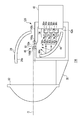
- FIG. 1 is a cross-sectional view illustrating a configuration of a vehicular lamp 10 according to the first embodiment.
- the vehicular lamp 10 is used as a vehicle headlamp.
- the vehicular lamp 10 is disposed on each of the left and right sides of the front portion of the vehicle body.
- the vehicle lamp 10 positioned on the right side when viewed from the front of the vehicle body will be described.
- the left vehicular lamp 10 basically has the same configuration.
- the vehicle lamp 10 includes a lamp body 12, a translucent cover 14, a lamp unit 16, and an extension reflector 18.
- the lamp body 12 is formed in a box shape having an opening.
- the translucent cover 14 is formed in a bowl shape with resin or glass having translucency. The translucent cover 14 is attached to the lamp body 12 so as to cover the opening of the lamp body 12.
- the lamp unit 16 is disposed in a lamp chamber 20 formed by the lamp body 12 and the translucent cover 14.
- the lamp unit 16 is a so-called projector type optical unit.
- the lamp unit 16 is attached to substantially the center of the metal support member 22 arranged so that the main surface faces the lamp front-rear direction.
- the metal support member 22 is tiltably supported by the lamp body 12 by the aiming screw 24. When the aiming screw 24 rotates, the metal support member 22 tilts, and the lamp unit 16 tilts accordingly. Thereby, the optical axis of the lamp unit 16 can be adjusted in the horizontal direction and the vertical direction.
- the extension reflector 18 is arranged in the lamp chamber 20 similarly to the lamp body 12.
- the extension reflector 18 is disposed so as to cover a region between the opening of the lamp body 12 and the outer periphery of the lamp unit 16. Thereby, the internal structure of the vehicular lamp 10 can be hidden.
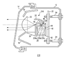
- FIG. 2 is a cross-sectional view showing the lamp unit 16 of FIG.
- the lamp unit 16 includes a light source module 26, a reflector 28, a lens holder 30, and a projection lens 32.
- the reflector 28 is a substantially dome-shaped member, and is disposed above the light source module 26. In particular, the reflector 28 is disposed so as to face an emission surface 50a of a phosphor 50 (described later).
- the reflector 28 has a reflection surface 28a on the inner side based on a spheroid.
- the reflective surface 28a has a first focal point and a second focal point located on the front side of the lamp relative to the first focal point.
- the reflector 28 has a positional relationship with the phosphor 50 so that the first focal point of the reflecting surface 28 a substantially coincides with the phosphor 50.
- the lens holder 30 is a member extending in the front-rear direction.
- the rear side of the lens holder 30 is fixed to the light source module 26.
- a projection lens 32 is fixed to the front side of the lens holder 30.
- the projection lens 32 is a plano-convex aspheric lens having a convex front surface and a flat rear surface.
- the projection lens 32 projects the light source image formed on the rear focal plane including the rear focus on the virtual vertical screen in front of the lamp as a reverse image.
- the light source module 26 includes a light source unit 34, a heat sink 42, a condensing reflector 44, a phosphor module 46, and a case 48.
- the case 48 is formed in a box shape. A light source unit 34 and a light collecting reflector 44 are accommodated in the case 48.
- the light source unit 34 includes a first light source unit 34a, a second light source unit 34b, and a third light source unit 34c.
- the first light source unit 34a includes a first light source 36a, a first substrate 38a, and a first lens 40a.
- the first light source 36a is a laser diode that emits blue laser light.
- the first light source 36a is a laser diode having a peak wavelength in the wavelength range of 380 to 470 nm.
- the first light source 36a may be a laser device such as a solid-state laser or a gas laser.
- the first substrate 38 a is attached to the front surface 42 a of the heat sink 42.
- the first light source 36a is mounted on the first substrate 38a so that the laser emission surface faces the front of the lamp.
- the first lens 40 a is provided between the first light source 36 a and the condensing reflector 44.
- the first lens 40a converts the laser light traveling from the first light source 36a toward the condensing reflector 44 into parallel light.
- the first lens 40a may have a function of adjusting the tilt angle in the vertical direction. In this case, the tilt error due to the dimensional error of the first substrate 38a can be corrected.
- the second light source unit 34b includes a second light source 36b, a second substrate 38b, and a second lens 40b.
- the third light source unit 34c includes a third light source 36c, a third substrate 38c, and a third lens 40c.
- the second light source 36b and the third light source 36c have the same configuration as the first light source 36a.
- the second substrate 38b and the third substrate 38c have the same configuration as the first substrate 38a.
- the second lens 40b and the third lens 40c have the same configuration as the first lens 40a.
- the 2nd lens 40b and the 3rd lens 40c may have a function which can adjust the inclination angle of an up-down direction.
- the heat sink 42 is formed of a material having high thermal conductivity such as aluminum.
- the front surface 42a of the heat sink 42 has a flat shape.
- a first substrate 38a on which the first light source 36a is mounted, a second substrate 38b on which the second light source 36b is mounted, and a third substrate 38c on which the third light source 36c is mounted are attached to the front surface 42a.
- the first substrate 38a, the second substrate 38b, and the third substrate 38c are arranged so that their rear surfaces are on the same plane, so that the front surface 42a of the heat sink 42 is made flat. Can do.
- the heat sink 42 is provided such that the front surface 42 a side slightly enters the case 48 from a through hole 48 b formed in the back surface 48 a of the case 48, and the remaining portion protrudes outside the case 48. Thereby, the heat generated by each light source can be dissipated outside the case 48, and the temperature rise of the light source and the light source module 26 can be suppressed.
- the condensing reflector 44 is provided in front of the light source unit 34.
- the condensing reflector 44 has a reflecting surface 44a.
- the reflecting surface 44a has a shape based on a paraboloid of revolution having an axis Ax passing through the phosphor 50 as a central axis.
- the light source unit 34 is arranged so that the laser light from the light source unit 34 is incident on the reflecting surface 44a substantially parallel to the axis Ax.
- the phosphor 50 is disposed so as to coincide with the focal point of the reflecting surface 44a. Specifically, the phosphor 50 is arranged so that the center thereof substantially coincides with the focal point of the reflecting surface 44a.
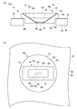
- FIG. 3 (a) and 3 (b) are diagrams showing the phosphor module 46 and its vicinity.
- FIG. 3A is a cross-sectional view taken along line AA in FIG.
- FIG.3 (b) is the figure which looked at Fig.3 (a) from the top.
- the phosphor module 46 includes a phosphor 50, a wavelength selection filter 52, and a holding member 53.
- the holding member 53 is formed from various metal materials.
- the holding member 53 is made of iron, SUS, brass (brass), molybdenum, tungsten, or an alloy thereof.
- the holding member 53 includes an upper part 53a and a lower part 53b each having a cylindrical outer peripheral surface.
- the outer peripheral surface of the lower part 53b has a smaller outer diameter than the outer peripheral surface of the upper part 53a.
- a through hole 48d having a diameter larger than the outer diameter of the lower portion 53b (for example, a diameter larger by several millimeters) is formed in the upper surface 48c of the case 48.
- the holding member 53 is fixed to the case 48 with the lower side portion 53 b entering the through hole 48 d and the lower surface of the upper portion 53 a placed on the upper surface 48 c of the case 48. Specifically, the holding member 53 is adjusted in the horizontal position with the lower portion 53b entering the through hole 48d, and is fixed to the case 48 by resistance welding, laser welding, arc welding, soldering, or caulking.
- a through hole 58 that communicates the upper surface 53c of the upper portion 53a and the lower surface 53d of the lower portion 53b is formed in the approximate center of the holding member 53.
- the through hole 58 is formed so that its cross-sectional area increases as it goes upward. Therefore, the inner wall 58a of the through hole 58 is inclined.
- the through hole 58 is formed such that the shape of the inner wall 58a in the vertical cross section is a straight line.
- the through-hole 58 is formed so that its cross-sectional shape becomes longer as it goes upward.
- the through-hole 58 is formed so that the ratio between the dimension in the short direction and the dimension in the long direction in the cross section increases as it goes upward.
- the opening 58b on the lower surface 53d side of the through hole 58 has a substantially circular shape.
- the opening 58c on the upper surface 53c side of the through hole 58 has a substantially oval shape. Therefore, the outer periphery of the opening 58c includes a pair of linear sides 58d and 58e extending in the longitudinal direction of the opening 58c.
- the shape of the through hole 58 in the cross section passing through the emission surface 50a also has a substantially oval shape.
- the through hole 58 is formed such that the dimension D1 in the longitudinal direction at the opening 58c on the upper surface 53c side is twice to four times the dimension D2 in the short direction. That is, the opening 58c is formed so that the ratio of the short direction to the long direction is 1: 2 to 1: 4.
- the phosphor 50 absorbs part of the blue laser light from the light source unit 34 and emits yellow light to Lambertian. The remaining laser light is emitted from the phosphor 50 without being absorbed by the phosphor 50. Since the structure of the phosphor 50 is known, a detailed description is omitted. The yellow light emitted from the phosphor 50 and the blue laser light emitted without being absorbed are mixed to generate white light. White light travels toward the reflector 28.
- the phosphor 50 has a shape corresponding to the shape of the through hole 58 of the holding member 53.
- the through hole 58 of the holding member 53 has a shape corresponding to the shape of the phosphor 50.
- the phosphor 50 is formed so that its cross-sectional area increases as it goes upward.
- the fluorescent substance 50 is formed so that the cross-sectional shape becomes longer as it goes upward.
- the phosphor 50 is formed such that the ratio between the dimension in the short direction and the dimension in the long direction in the cross section increases as it goes upward.
- the emission surface 50a of the phosphor 50 has a substantially oval shape. Therefore, the outer periphery of the emission surface 50a includes a pair of linear sides 50c and 50d extending in the longitudinal direction. The sides 50c and 50d particularly extend in the same direction as the sides 58d and 58e of the opening 58c.
- the phosphor 50 is formed such that the dimension D3 in the longitudinal direction on the emission surface 50a is twice to four times the dimension D4 in the short direction. That is, the phosphor 50 is formed so that the ratio of the short direction to the long direction of the emission surface 50a is 1: 2 to 1: 4.
- the wavelength selection filter 52 is provided below the phosphor 50, that is, between the phosphor 50 and the light source unit 34.
- the wavelength selection filter 52 transmits the blue laser light from the light source unit 34. Further, the wavelength selection filter 52 reflects light traveling downward among the yellow light emitted from the phosphor 50. Thereby, the utilization efficiency of the light from the fluorescent substance 50 can be improved.
- the wavelength selection filter 52 is a dielectric multilayer film formed on the lower surface of the phosphor 50 by vapor deposition.
- the dielectric multilayer film is a thin film in which dielectric materials having different refractive indexes are alternately laminated in multiple layers. Due to the effects of multiple reflection and multiple interference, it transmits almost 100% of blue light having a wavelength of 380 to 470 nm, and has a wavelength of 471 to 471. Reflects approximately 100% of light at 800 nm. Note that the reflectance of light having a wavelength of 471 to 800 nm by the dielectric multilayer film may not be approximately 100%. For example, it may be approximately 50%, approximately 80%, or other reflectance.
- the phosphor 50 and the wavelength selection filter 52 are inserted into the through hole 58 so that the side surfaces thereof are in contact with the inner wall 58a of the through hole 58, and are fixed by press-fitting or adhesion.
- the phosphor 50 and the wavelength selection filter 52 may be fixed by being sealed with a transparent member such as glass.
- a reflective film 54 is provided on the inner wall 58 a of the through hole 58. Therefore, the inner wall 58a of the through hole 58 functions as a reflecting surface. At least a part of the light directed downward in the Lambertian light in the phosphor 50 is reflected by the reflective film 54 and travels upward, that is, toward the reflector 28. Thereby, the utilization efficiency of the light from the fluorescent substance 50 can be improved.
- the inner wall 58a of the through hole 58 protrudes above the phosphor 50. That is, the annular reflecting surface protrudes above the phosphor 50. With the reflecting surface protruding upward, the light emitted from the phosphor 50 to Lambertian can be given directivity.
- the protruding annular reflecting surface is formed such that the dimension D5 in the vertical direction is 1.2 to 1.8 times the dimension D6 in the vertical direction of the phosphor 50. More preferably, it is formed to be 1.4 to 1.6 times.
- FIG. 4 is an explanatory diagram for explaining these relationships.
- the beam pattern P1 indicates the cross-sectional shape of the laser light on the opening 58b of the through hole 58.
- the beam pattern P2 indicates the cross-sectional shape of the laser light on the incident surface 50b of the phosphor 50.
- the beam pattern P3 indicates the cross-sectional shape of the laser light on the emission surface 50a of the phosphor 50.
- the laser beam has a long cross section, and spreads away from the light source. In FIG. 4, the thickness and the extent of spread of the laser beam are exaggerated.
- the opening 58b of the through hole 58 is larger than the beam pattern P1 of the laser beam.
- the diameter of the opening 58b is larger than the dimension in the longitudinal direction of the beam pattern P1 of the laser light.
- the diameter of the opening 58b may be substantially the same as the dimension in the longitudinal direction of the beam pattern P1 of the laser beam.
- the incident surface 50b of the phosphor 50 is larger than the beam pattern P2 of the laser beam.
- the longitudinal dimension of the incident surface 50b is larger than the longitudinal dimension of the laser beam pattern P2.
- the dimension in the longitudinal direction of the incident surface 50b may be substantially the same as the beam pattern P2 of the laser light.
- the case 48 is configured such that the upper surface 48c thereof includes the optical axis O and the ridge line 48f formed by the upper surface 48c and the front surface 48e is positioned in the vicinity of the second focal point of the reflector 28.
- the light reflected by the reflector 28 enters the projection lens 32 through the second focal point of the reflector 28, that is, the vicinity of the ridge line 48f.
- a reflective film 56 is provided on the upper surface 48 c of the case 48 (see FIG. 3), and a part of the light reflected by the reflector 28 is reflected by the reflective film 56. Therefore, the light from the reflector 28 is cut with the ridge line 48f as a boundary line. Thereby, the light distribution pattern which has the cut-off line corresponding to the shape of the ridgeline 48f is projected ahead of the vehicle. That is, part of the case 48 functions as a shade.
- the first light source 36a, the second light source 36b, and the third light source 36c emit laser light.
- Each laser beam is converted into parallel light by the first lens 40 a, the second lens 40 b, and the third lens 40 c and enters the reflecting surface 44 a of the condensing reflector 44.
- the laser light incident on the condensing reflector 44 is reflected toward the approximate center of the phosphor 50.
- the phosphor 50 absorbs a part of the incident laser light and emits yellow light. The remaining laser light is emitted from the phosphor 50 without being absorbed by the phosphor 50.
- the yellow light and the blue light of the laser light are mixed to generate white light and travel toward the reflector 28.
- the reflecting surface 28 a of the reflector 28 reflects white light toward the projection lens 32.
- the projection lens 32 irradiates the light from the reflector 28 in front of the lamp as substantially parallel light.
- the emission surface 50a of the phosphor 50 has a long shape.
- the phosphor 50 includes a pair of straight sides 50c and 50d extending in the longitudinal direction on the outer periphery of the emission surface 50a. For this reason, when the light source module 26 is used as a light source of the vehicular lamp 10, it becomes easy to form a cut-off line. That is, the light source module suitable for the light source of the vehicular lamp can be realized.
- the phosphor 50 is formed so that the ratio of the short direction D4 and the long direction D3 on the emission surface 50a is 1: 2 to 1: 4.
- the upper opening 58c of the through hole 58 is formed so that the ratio of the short direction D2 to the long direction D1 is 1: 2 to 1: 4. That is, the light source module 26 having an aspect ratio suitable for the light source of the vehicular lamp can be realized.
- the phosphor D so that the dimension D 5 in the vertical direction of the reflecting surface protruding above the phosphor 50 is 1.2 to 1.8 times the dimension D 6 in the vertical direction of the phosphor 50.
- a module 46 is formed. More preferably, it is formed to be 1.4 to 1.6 times. Thereby, a light source module having a desired size and a desired luminance can be realized.
- the phosphor 50 is formed such that its cross-sectional area increases as it goes upward.
- the through hole 58 of the holding member 53 has a shape corresponding to the shape of the phosphor 50 and is formed so that its cross-sectional area increases as it goes upward. That is, the through hole 58 of the holding member 53 is formed so that the phosphor 50 cannot pass through. Since the phosphor 50 is held by the through hole 58 formed in this way, it is possible to prevent the phosphor 50 from dropping from the holding member 53.
- the laser light from the plurality of light source units 34 is condensed on the phosphor 50 by the reflection surface 44 a of the condensing reflector 44. Therefore, there is no loss at the time of incidence, light guidance, and emission, for example, when condensing with a light guide such as an optical fiber, so that the utilization efficiency of laser light is improved.
- the light source module 26 can be reduced in size compared to the case where light is collected by a light guide such as an optical fiber, which can contribute to the reduction in size of the vehicular lamp 10 on which the light source module 26 is mounted.
- the laser light from the plurality of light source units 34 is condensed on the phosphor 50 by the reflection surface 44a based on the paraboloid of revolution. Therefore, if the laser light from the light source unit 34 is incident on the reflecting surface 44a substantially parallel to the axis Ax that is the central axis of the reflecting surface 44a, the laser light is focused on the phosphor 50. That is, if the laser beam from the light source unit 34 is substantially parallel to the axis Ax, the distance between each member constituting the light source unit 34 and the axis Ax and the distance between each member and the reflecting surface 44a are not questioned. . Therefore, the position adjustment of the light source unit 34 is relatively easy.
- the first light source 36a, the second light source 36b, and the third light source 36c are accommodated in the case 48. For this reason, even if these light sources are removed, the laser light is prevented from being directly emitted to the outside of the light source module 26 and, consequently, directly emitted to the outside of the vehicle lamp 10 on which the light source module 26 is mounted.
- the first substrate 38a, the second substrate 38b, and the third substrate 38c are arranged so that the surfaces on the heat sink 42 side are located on the same plane, so that the front surface 42a of the heat sink 42 is flat. Can be made into any shape. For this reason, the heat sink 42 can be made into a single member and a relatively simple shape, and the number of heat sinks 42 and the processing cost can be reduced.
- FIG. 5 is a cross-sectional view showing the lamp unit 116 of the vehicular lamp according to the second embodiment.
- FIG. 5 corresponds to FIG.
- the lamp unit 116 includes a light source module 126, a reflector 28, a lens holder 30, and a projection lens 32.
- the light source module 126 includes a light source unit 34, a heat sink 42, a condensing reflector 44, a phosphor module 46, and a case 148.
- Case 148 is formed in a box shape. The case 148 houses the light source unit 34 and the condensing reflector 44.
- the upper surface 148c of the case 148 has an inclined portion 148g inclined backward.
- a through hole 148d is formed in the inclined portion 148g.
- the phosphor module 46 is fixed to the through hole 148d in the same manner as in the first embodiment.
- the phosphor module 46 is fixed so that the emission surface 50 a of the phosphor 50 is inclined backward with respect to the central axis of the reflection surface 28 a of the reflector 28.
- the central axis of the reflecting surface 28a substantially coincides with the optical axis O.
- the same effects as the effects obtained by the light source module 126 according to the second embodiment and the light source module 26 according to the first embodiment are exhibited.
- played by the vehicle lamp 10 which concerns on 1st Embodiment is show
- the emission surface 50a of the phosphor 50 is fixed so as to incline backward with respect to the central axis of the reflection surface 28a of the reflector 28. Thereby, the utilization solid angle of the reflective surface 28a of the reflector 28 can be increased.
- FIG. 6 is a cross-sectional view showing a vehicular lamp 210 according to the third embodiment.
- FIG. 6 corresponds to FIG.
- the vehicular lamp 210 includes the lamp body 12, the translucent cover 14, the lamp unit 216, and the extension reflector 18.
- the lamp unit 216 includes a light source module 226, a reflector 28, a lens holder 30, and a projection lens 32.
- the first light source 236a, the second light source 236b, and the third light source 236c of the light source module 226 are arranged in the front-rear direction, and their laser emission ports are on the lamp body 12 side (left-right direction in FIG. 6). It is arranged to face.
- the same operational effects as the operational effects exhibited by the light source module 26 according to the first embodiment are exhibited.
- the emission ports of the respective light sources are arranged so as to face the lamp body 12 side. Thereby, even if the case 48 and the condensing reflector 44 are removed, the laser light from each light source is prevented from being directly emitted to the outside of the lamp.
- FIG. 7 is a cross-sectional view showing a lamp unit 316 of a vehicle lamp according to the fourth embodiment.
- FIG. 7 corresponds to FIG.
- the lamp unit 316 includes a light source module 326, a reflector 28, a lens holder 30, and a projection lens 32.
- the light source module 326 includes a light source unit 334, a heat sink 42, a condenser lens 344, a phosphor module 46, and a case 48.
- the case 48 houses a light source unit 334 and a condenser lens 344.
- the light source unit 334 includes a light source 336 and a substrate 338. The light source 336 and the substrate 338 correspond to the first light source 36a and the first substrate 38a of the first embodiment, respectively.
- the condenser lens 344 is provided between the light source 336 and the phosphor 50. Laser light emitted from the light source 336 is condensed by the condenser lens 344 and enters the phosphor 50.
- the vehicular lamp 10 may include a lens that converts laser light emitted from the light source 336 into parallel light instead of the condenser lens 344.
- the same operational effects as the operational effects exhibited by the light source module 26 according to the first embodiment are exhibited.
- the effect similar to the effect shown by the vehicle lamp 10 which concerns on 1st Embodiment is show
- the light source module 26 includes the three light source units of the first light source unit 34a, the second light source unit 34b, and the third light source unit 34c has been described.
- the present invention is not limited to this.
- the light source module 26 may include two, or four or more light source units.
- the light source units are arranged in the vertical direction, and in the third embodiment, the light source units are arranged in the front-rear direction.
- the present invention is not limited to this.
- the light source units may be arranged in the left-right direction (the paper surface direction in FIG. 2).
- four or more light source units may be arranged in a matrix.
- five or more light source units may be arranged in a cross shape.
- each light source unit may be arranged irregularly. That is, the laser beams from the plurality of light source units may be arranged so as to enter the reflecting surface 44a substantially parallel to the axis Ax.
- the light source unit emits blue laser light
- the phosphor 50 absorbs the blue laser light and emits yellow light
- the yellow light and the blue laser light are
- the light source unit may emit ultraviolet laser light
- the phosphor may be configured to absorb ultraviolet laser light and emit blue light and yellow light. In this case, blue light emitted from the phosphor and yellow light are mixed to generate white light.
- the light source unit may emit an ultraviolet laser beam
- the phosphor may absorb the ultraviolet laser beam and emit red light, green light, and blue light.
- red light, green light, and blue light emitted from the phosphor are mixed to generate white light.
- At least one of the plurality of light source units is provided such that the laser light from the light source unit is incident on the emission surface 50a of the phosphor 50 substantially at right angles. Also good. In this case, the emission loss at the emission surface 50a of the phosphor 50 is suppressed, and the light utilization efficiency is improved.
- the lamp unit is a so-called projector-type optical unit.
- the present invention is not limited to this.
- the lamp unit may be a so-called parabolic optical unit.
- FIG. 8 is a cross-sectional view showing a lamp unit 416 of a vehicle lamp according to a modification.
- the lamp unit 416 includes a so-called parabolic light source module 26 and a reflector 428.
- the reflector 428 is a substantially dome-shaped member and is disposed above the light source module 26.
- the reflector 428 has a reflection surface 428a on the inner side based on a paraboloid of revolution.
- the positional relationship between the reflector 428 and the phosphor 50 is determined so that the focal point of the reflecting surface 428 a coincides with the phosphor 50.
- the reflector 428 irradiates light from the light source module 26 in front of the lamp.
- FIGS. 9A and 9B show a phosphor module 546 of a light source module according to a modification.
- FIGS. 9A and 9B correspond to FIGS. 3A and 3B.
- the opening 58b may be formed in a long shape.
- the opening 58b may be formed in a shape substantially the same as the cross-sectional shape of the laser light on the opening 58b, or a shape substantially similar to the cross-sectional shape of the laser light on the opening 58b.
- the incident surface 50b has substantially the same cross-sectional shape as the laser beam on the incident surface 50b or the laser beam on the incident surface 50b. It may be formed in a shape substantially similar to the cross-sectional shape.
- the emission surface 50a of the phosphor 50 has an oval shape.
- the present invention is not limited to this.
- the emission surface 50a may have, for example, a substantially rectangular shape. That is, the emission surface 50a only needs to have a long shape and include a pair of straight sides whose outer periphery extends in the long direction.
- the opening 58c of the through hole 58 has an oval shape, but the present invention is not limited to this.
- the opening 58c may have a substantially rectangular shape, for example. That is, the opening 58c only needs to have a long shape and include a pair of straight sides whose outer periphery extends in the long direction.
- FIGS. 10A and 10B show a phosphor module 646 of a light source module according to a modification.
- FIGS. 10A and 10B correspond to FIGS. 3A and 3B.
- the phosphor 50 is formed integrally with the holding member 53.
- the phosphor 50 is formed by using the holding member 53 as a mold. Specifically, the opening 58b on the lower surface 53d side of the holding member 53 is closed, a resin or ceramic containing a fluorescent material is injected into the through hole 58 in which the opening 58b is closed, and the holding member 53 is sintered together. A phosphor 50 is formed.
- the metal mesh 660 is coupled to the inner wall 58a of the holding member 53, the mesh 660 and the phosphor 50 are integrated by forming the phosphor 50 as described above.
- the same operational effects as the operational effects exhibited by the light source modules according to the first to fourth embodiments are exhibited.
- the phosphor 50 is sintered and formed in a state where a resin or ceramic containing a fluorescent material is injected into the through hole 58 of the holding member 53. Therefore, the process of assembling the phosphor 50 to the holding member 53 becomes unnecessary.
- the phosphor 50 is integrated with the mesh 660 coupled to the holding member 53. Therefore, dropping off of the phosphor 50 is suppressed.
- the phosphor 50 is integrated with a metal mesh 660 coupled to the holding member 53. Therefore, the heat generated in the phosphor 50 is transmitted to the holding member 53 through the mesh 660 and is radiated. That is, according to this modification, the heat dissipation performance of the phosphor 50 can be enhanced, and a decrease in the light emission efficiency (laser light conversion efficiency) of the phosphor 50 due to heat generation can be suppressed. As a result, the brightness of the phosphor 50 can be increased, and the phosphor 50 can be suitably used as a light source for a vehicular lamp.
- the protrusion of the phosphor 50 can be suppressed by the protrusion, and the heat dissipation performance of the phosphor 50 can be improved by the protrusion.
- the present invention can be used for a light source module and a vehicular lamp provided with the light source module.
Abstract
Cette invention concerne un dispositif d'éclairage pour un véhicule, comprenant : une première source de lumière (36a), une deuxième source de lumière (36b), et une troisième source de lumière (36c) qui émettent une lumière laser ; une première lentille (40a), une deuxième lentille (40b), et une troisième lentille (40c) pour paralléliser la lumière laser émise par les sources de lumière ; un réflecteur de concentration (44) qui comprend une surface réfléchissante (44a) ayant comme base une forme de surface paraboloïde de révolution qui réfléchit la lumière laser qui a traversé respectivement les lentilles ; et un corps fluorescent (50) qui reçoit la lumière laser qui a été réfléchie par le réflecteur de concentration (44) et émet de la lumière.
Priority Applications (2)
| Application Number | Priority Date | Filing Date | Title |
|---|---|---|---|
| JP2016517910A JP6654560B2 (ja) | 2014-05-07 | 2015-05-07 | 光源モジュールおよび車両用灯具 |
| US15/278,985 US20170016586A1 (en) | 2014-05-07 | 2016-09-28 | Light source module and vehicle lamp |
Applications Claiming Priority (4)
| Application Number | Priority Date | Filing Date | Title |
|---|---|---|---|
| JP2014096203 | 2014-05-07 | ||
| JP2014-096203 | 2014-05-07 | ||
| JP2014-106484 | 2014-05-22 | ||
| JP2014106484 | 2014-05-22 |
Related Child Applications (1)
| Application Number | Title | Priority Date | Filing Date |
|---|---|---|---|
| US15/278,985 Continuation US20170016586A1 (en) | 2014-05-07 | 2016-09-28 | Light source module and vehicle lamp |
Publications (1)
| Publication Number | Publication Date |
|---|---|
| WO2015170696A1 true WO2015170696A1 (fr) | 2015-11-12 |
Family
ID=54392546
Family Applications (1)
| Application Number | Title | Priority Date | Filing Date |
|---|---|---|---|
| PCT/JP2015/063169 WO2015170696A1 (fr) | 2014-05-07 | 2015-05-07 | Module de source de lumière et dispositif d'éclairage pour véhicule |
Country Status (3)
| Country | Link |
|---|---|
| US (1) | US20170016586A1 (fr) |
| JP (1) | JP6654560B2 (fr) |
| WO (1) | WO2015170696A1 (fr) |
Cited By (11)
| Publication number | Priority date | Publication date | Assignee | Title |
|---|---|---|---|---|
| EP3181995A1 (fr) * | 2015-12-15 | 2017-06-21 | LG Innotek Co., Ltd. | Dispositif électroluminescent et appareil d'éclairage pour véhicules comprenant celui-ci |
| KR20170121570A (ko) * | 2016-04-25 | 2017-11-02 | 엘지이노텍 주식회사 | 조명장치 |
| WO2017191031A1 (fr) * | 2016-05-04 | 2017-11-09 | Osram Gmbh | Dispositif optique et phare de véhicule |
| CN107525042A (zh) * | 2016-06-22 | 2017-12-29 | Lg伊诺特有限公司 | 磷光板和包括该磷光板的照明装置 |
| EP3255687A4 (fr) * | 2015-02-03 | 2018-01-24 | LG Innotek Co., Ltd. | Dispositif émettant de la lumière |
| JP2018037472A (ja) * | 2016-08-30 | 2018-03-08 | 日亜化学工業株式会社 | 発光装置 |
| KR20180067368A (ko) * | 2016-12-12 | 2018-06-20 | 에스엘 주식회사 | 차량용 램프 |
| KR20180077976A (ko) * | 2016-12-29 | 2018-07-09 | 에스엘 주식회사 | 차량용 램프 |
| CN108474533A (zh) * | 2016-02-03 | 2018-08-31 | 欧司朗股份有限公司 | 用于发射照明光的照明设备 |
| JP2019003866A (ja) * | 2017-06-16 | 2019-01-10 | 株式会社小糸製作所 | 車両用灯具 |
| US10330276B2 (en) | 2016-10-14 | 2019-06-25 | Koito Manufacturing Co., Ltd. | Vehicular headlamp |
Families Citing this family (5)
| Publication number | Priority date | Publication date | Assignee | Title |
|---|---|---|---|---|
| KR102555300B1 (ko) * | 2016-04-18 | 2023-07-19 | 엘지이노텍 주식회사 | 조명 장치 |
| WO2018100758A1 (fr) * | 2016-11-30 | 2018-06-07 | パナソニックIpマネジメント株式会社 | Système optique et dispositif de source lumineuse |
| JP6975552B2 (ja) * | 2017-05-24 | 2021-12-01 | スタンレー電気株式会社 | 車両用灯具 |
| EP3415367A1 (fr) * | 2017-06-16 | 2018-12-19 | Valeo Iluminacion | Dispositif et procédé de commande de sources lumineuses dans des véhicules à moteur |
| JP7298094B2 (ja) * | 2019-09-09 | 2023-06-27 | 株式会社東海理化電機製作所 | 車両用投射装置及び車両用視認装置 |
Citations (5)
| Publication number | Priority date | Publication date | Assignee | Title |
|---|---|---|---|---|
| JP2012109220A (ja) * | 2010-10-29 | 2012-06-07 | Sharp Corp | 発光装置、照明装置、車両用前照灯および車両 |
| JP2012109201A (ja) * | 2010-10-29 | 2012-06-07 | Sharp Corp | 発光装置、車両用前照灯、照明装置およびレーザ素子 |
| JP2012169375A (ja) * | 2011-02-10 | 2012-09-06 | Sharp Corp | 光源装置、照明装置および車両用前照灯 |
| JP2014017094A (ja) * | 2012-07-06 | 2014-01-30 | Sharp Corp | 照明装置および車両用前照灯 |
| JP2014022084A (ja) * | 2012-07-13 | 2014-02-03 | Koito Mfg Co Ltd | 車両用灯具 |
Family Cites Families (7)
| Publication number | Priority date | Publication date | Assignee | Title |
|---|---|---|---|---|
| JP2006127856A (ja) * | 2004-10-27 | 2006-05-18 | Koito Mfg Co Ltd | 車両用照明灯具 |
| JP5271590B2 (ja) * | 2008-04-22 | 2013-08-21 | 株式会社小糸製作所 | 車両用灯具 |
| JP5053416B2 (ja) * | 2010-05-17 | 2012-10-17 | シャープ株式会社 | 発光装置、照明装置および車両用前照灯 |
| JP5487077B2 (ja) * | 2010-10-29 | 2014-05-07 | シャープ株式会社 | 発光装置、車両用前照灯および照明装置 |
| JP5968682B2 (ja) * | 2012-05-24 | 2016-08-10 | シャープ株式会社 | 投光装置および車両用前照灯 |
| WO2014141030A1 (fr) * | 2013-03-11 | 2014-09-18 | Koninklijke Philips N.V. | Module de diode électroluminescente doté de caractéristiques lumineuses améliorées |
| WO2014162683A1 (fr) * | 2013-04-04 | 2014-10-09 | 株式会社小糸製作所 | Accessoire de lampe de véhicule |
-
2015
- 2015-05-07 JP JP2016517910A patent/JP6654560B2/ja active Active
- 2015-05-07 WO PCT/JP2015/063169 patent/WO2015170696A1/fr active Application Filing
-
2016
- 2016-09-28 US US15/278,985 patent/US20170016586A1/en not_active Abandoned
Patent Citations (5)
| Publication number | Priority date | Publication date | Assignee | Title |
|---|---|---|---|---|
| JP2012109220A (ja) * | 2010-10-29 | 2012-06-07 | Sharp Corp | 発光装置、照明装置、車両用前照灯および車両 |
| JP2012109201A (ja) * | 2010-10-29 | 2012-06-07 | Sharp Corp | 発光装置、車両用前照灯、照明装置およびレーザ素子 |
| JP2012169375A (ja) * | 2011-02-10 | 2012-09-06 | Sharp Corp | 光源装置、照明装置および車両用前照灯 |
| JP2014017094A (ja) * | 2012-07-06 | 2014-01-30 | Sharp Corp | 照明装置および車両用前照灯 |
| JP2014022084A (ja) * | 2012-07-13 | 2014-02-03 | Koito Mfg Co Ltd | 車両用灯具 |
Cited By (22)
| Publication number | Priority date | Publication date | Assignee | Title |
|---|---|---|---|---|
| US10408421B2 (en) | 2015-02-03 | 2019-09-10 | Lg Innotek Co, Ltd. | Light emitting apparatus |
| EP3255687A4 (fr) * | 2015-02-03 | 2018-01-24 | LG Innotek Co., Ltd. | Dispositif émettant de la lumière |
| US10371337B2 (en) | 2015-12-15 | 2019-08-06 | Lg Innotek Co., Ltd. | Light-emitting apparatus and lighting apparatus for vehicles including the same |
| KR20170070994A (ko) * | 2015-12-15 | 2017-06-23 | 엘지이노텍 주식회사 | 발광 장치 및 이를 포함하는 차량용 조명 장치 |
| CN106996534A (zh) * | 2015-12-15 | 2017-08-01 | Lg伊诺特有限公司 | 发光设备和用于包括该发光设备的车辆的照明设备 |
| EP3181995A1 (fr) * | 2015-12-15 | 2017-06-21 | LG Innotek Co., Ltd. | Dispositif électroluminescent et appareil d'éclairage pour véhicules comprenant celui-ci |
| KR102513407B1 (ko) * | 2015-12-15 | 2023-03-23 | 엘지이노텍 주식회사 | 발광 장치 및 이를 포함하는 차량용 조명 장치 |
| CN108474533B (zh) * | 2016-02-03 | 2021-02-02 | 欧司朗股份有限公司 | 用于发射照明光的照明设备 |
| CN108474533A (zh) * | 2016-02-03 | 2018-08-31 | 欧司朗股份有限公司 | 用于发射照明光的照明设备 |
| KR20170121570A (ko) * | 2016-04-25 | 2017-11-02 | 엘지이노텍 주식회사 | 조명장치 |
| KR102525592B1 (ko) | 2016-04-25 | 2023-05-03 | 엘지이노텍 주식회사 | 조명장치 |
| WO2017191031A1 (fr) * | 2016-05-04 | 2017-11-09 | Osram Gmbh | Dispositif optique et phare de véhicule |
| US10928035B2 (en) | 2016-06-22 | 2021-02-23 | Lg Innotek Co., Ltd. | Phosphor plate and lighting device including the same |
| EP3267095A1 (fr) * | 2016-06-22 | 2018-01-10 | LG Innotek Co., Ltd. | Plaque de phosphore et dispositif d'éclairage la comprenant |
| CN107525042A (zh) * | 2016-06-22 | 2017-12-29 | Lg伊诺特有限公司 | 磷光板和包括该磷光板的照明装置 |
| JP2018037472A (ja) * | 2016-08-30 | 2018-03-08 | 日亜化学工業株式会社 | 発光装置 |
| US10330276B2 (en) | 2016-10-14 | 2019-06-25 | Koito Manufacturing Co., Ltd. | Vehicular headlamp |
| KR101959806B1 (ko) * | 2016-12-12 | 2019-03-20 | 에스엘 주식회사 | 차량용 램프 |
| KR20180067368A (ko) * | 2016-12-12 | 2018-06-20 | 에스엘 주식회사 | 차량용 램프 |
| KR101951463B1 (ko) * | 2016-12-29 | 2019-02-22 | 에스엘 주식회사 | 차량용 램프 |
| KR20180077976A (ko) * | 2016-12-29 | 2018-07-09 | 에스엘 주식회사 | 차량용 램프 |
| JP2019003866A (ja) * | 2017-06-16 | 2019-01-10 | 株式会社小糸製作所 | 車両用灯具 |
Also Published As
| Publication number | Publication date |
|---|---|
| JPWO2015170696A1 (ja) | 2017-04-20 |
| JP6654560B2 (ja) | 2020-02-26 |
| US20170016586A1 (en) | 2017-01-19 |
Similar Documents
| Publication | Publication Date | Title |
|---|---|---|
| WO2015170696A1 (fr) | Module de source de lumière et dispositif d'éclairage pour véhicule | |
| JP6506885B2 (ja) | 自動車両用投光装置の照明装置 | |
| JP5146214B2 (ja) | 車両用灯具 | |
| JP5567435B2 (ja) | 車両用灯具 | |
| JP5411910B2 (ja) | 光源システム | |
| JP4089866B2 (ja) | 投光ユニットおよび該投光ユニットを具備するled車両用照明灯具 | |
| JP6166270B2 (ja) | 発光デバイスおよびこれを用いた投影システム | |
| JP6144410B2 (ja) | 発光装置及び投影システム | |
| JP6257513B2 (ja) | 発光装置および車両用灯具 | |
| JP4526256B2 (ja) | 光源モジュールおよび該光源モジュールを具備する灯具 | |
| CN107036033B (zh) | 发光装置及照明系统 | |
| JP5518533B2 (ja) | 車両用前照灯および車両用前照灯用の発光モジュール | |
| JP4895224B2 (ja) | 車両用灯具 | |
| WO2011099640A1 (fr) | Lampe comprenant du phosphore, une source de rayonnement, un système optique et un puits thermique | |
| WO2014125782A1 (fr) | Appareil de lampe de véhicule | |
| JP2012169050A (ja) | 車両用灯具 | |
| JP6621631B2 (ja) | 光源モジュール | |
| WO2014163197A1 (fr) | Lampe de véhicule | |
| TWI487864B (zh) | 輻射發光裝置及其用途 | |
| JP2007324001A (ja) | 車両用灯具 | |
| WO2020052398A1 (fr) | Lampe de véhicule | |
| KR20160007922A (ko) | 헤드램프용 레이저 광학계 | |
| WO2015174312A1 (fr) | Module de source de lumière et dispositif d'éclairage pour véhicule | |
| WO2013118272A1 (fr) | Système optique d'éclairage et dispositif d'affichage du type à projection | |
| JP2014170758A (ja) | 照明装置、および車両用前照灯 |
Legal Events
| Date | Code | Title | Description |
|---|---|---|---|
| 121 | Ep: the epo has been informed by wipo that ep was designated in this application |
Ref document number: 15788849 Country of ref document: EP Kind code of ref document: A1 |
|
| ENP | Entry into the national phase |
Ref document number: 2016517910 Country of ref document: JP Kind code of ref document: A |
|
| NENP | Non-entry into the national phase |
Ref country code: DE |
|
| 122 | Ep: pct application non-entry in european phase |
Ref document number: 15788849 Country of ref document: EP Kind code of ref document: A1 |