WO2015170419A1 - 模型 - Google Patents
模型 Download PDFInfo
- Publication number
- WO2015170419A1 WO2015170419A1 PCT/JP2014/063433 JP2014063433W WO2015170419A1 WO 2015170419 A1 WO2015170419 A1 WO 2015170419A1 JP 2014063433 W JP2014063433 W JP 2014063433W WO 2015170419 A1 WO2015170419 A1 WO 2015170419A1
- Authority
- WO
- WIPO (PCT)
- Prior art keywords
- convex
- shaft
- model
- rotation
- shaft support
- Prior art date
- Legal status (The legal status is an assumption and is not a legal conclusion. Google has not performed a legal analysis and makes no representation as to the accuracy of the status listed.)
- Ceased
Links
Images



Classifications
-
- A—HUMAN NECESSITIES
- A63—SPORTS; GAMES; AMUSEMENTS
- A63H—TOYS, e.g. TOPS, DOLLS, HOOPS OR BUILDING BLOCKS
- A63H3/00—Dolls
- A63H3/36—Details; Accessories
- A63H3/46—Connections for limbs
Definitions
- the present invention relates to a model.
- a model including a first part and a second part connected to the first part so as to be rotatable relative to the first part is known (for example, see Patent Document 1).
- the leg 10 is connected to the trunk 1 so as to be rotatable.
- the body 1 has a protruding piece 2 and a sphere 20 fixed to the protruding piece 2, and the leg portion 10 has a storage chamber 12 for storing the sphere 20.
- the leg 10 is rotated by a sliding pair between the inner peripheral surface of the storage chamber 12 and the outer peripheral surface of the sphere 20.
- the leg portion 10 rotated by the sliding pair between the inner peripheral surface of the storage chamber 12 and the outer peripheral surface of the sphere 20 has the inner peripheral surface of the storage chamber 12 and the outer peripheral surface of the sphere 20. It is held in the state after rotation by the friction. However, as the rotation of the leg portion 10 is repeated, wear occurs on the inner peripheral surface of the storage chamber 12 and the outer peripheral surface of the spherical body 20, and the holding force of the leg portion 10 is reduced.
- the present invention has been made in view of the above-described circumstances, and an object of the present invention is to connect two portions so as to be relatively rotatable and to be able to reliably hold the state after the rotation.
- the model according to the present invention includes a first portion having a rotation shaft portion, and a shaft into which the rotation shaft portion is inserted and supports the inserted rotation shaft portion so as to be rotatable and movable in the axial direction.
- a second portion having a support portion and connected to the first portion so as to be rotatable relative to the first portion, and one of the first portion and the second portion is provided with a convex portion. The other is provided with a recess that fits with the projection and restricts the relative rotation of the second portion as the rotation shaft is inserted into the shaft support.
- the rotating shaft is between the first position where the moving shaft portion and the shaft support portion are engaged with each other, and the convex portion is fitted into the concave portion, and the second position where the convex portion is removed from the concave portion. It is characterized in that a locking part for restricting the movement of the part in the axial direction is provided.
- the convex portion is provided at a proximal end portion of the rotating shaft portion, and is formed in a polygon that is rotationally symmetric about the central axis of the rotating shaft portion,
- the concave portion may be provided at an opening edge of the shaft support portion and may be formed in the same polygon as the convex portion.
- the corners of the convex portions may be chamfered or rounded.
- the number of corners of the convex portion and the concave portion may be 4 or more and 6 or less.
- the locking portion of the rotating shaft portion is a groove formed in an annular shape on the outer periphery of the rotating shaft portion, and the locking portion of the shaft support portion is It may be a protrusion accommodated in the groove.
- the first part and the second part can be coupled so as to be relatively rotatable and to be able to reliably hold the state after the rotation.
- FIG. 1 shows an exploded configuration of an example of a model for explaining an embodiment of the present invention.
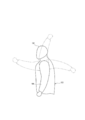
- the model 101 shown in FIG. 1 presents a doll as a whole, and includes a head 102, a torso 103, a pair of left and right arms 104, and a pair of left and right legs 105.
- the arm part 104 and the leg part 105 are connected to the body part 103 so as to be relatively rotatable.
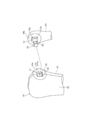
- FIG. 2 shows a connecting portion between the trunk portion 103 and the arm portion 104
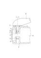
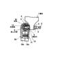
- FIGS. 3 and 4 show an internal configuration of the trunk portion 103 in the connecting portion.
- the arm portion 104 is provided with a rotation shaft portion 110
- the body portion 103 is provided with a shaft support portion 111 into which the rotation shaft portion 110 is inserted.
- the shaft support portion 111 supports the inserted rotation shaft portion 110 so as to be rotatable and movable in the axial direction.
- the trunk portion 103 may be provided with the rotation shaft portion 110
- the arm portion 104 may be provided with the shaft support portion 111.
- the arm portion 104 is provided with a convex portion 112, and the body portion 103 is provided with a concave portion 113 into which the convex portion 112 can be fitted.
- the convex portion 112 is provided at the proximal end portion of the rotating shaft portion 110, and the concave portion 113 is an opening edge portion of the insertion opening portion of the shaft support portion 111 into which the rotating shaft portion 110 is inserted. 111a.
- the convex part 112 and the recessed part 113 may be provided in the mutual contact surfaces 103a and 104a of the trunk
- the convex portion 112 provided at the base end portion of the rotation shaft portion 110 is formed in a polygon that is rotationally symmetric around the central axis of the rotation shaft portion 110, and the concave portion 113 in which the convex portion 112 can be fitted is a shaft It is a polygon that is rotationally symmetric around the central axis of the support portion 111 and the same polygon as the convex portion 112.
- the outer edges of the convex portion 112 and the concave portion 113 are formed in a square shape.
- corner 112a of the convex 112 formed in a polygon is chamfered or rounded.
- the body part 103 is divided into a first member 106 on the front side and a second member 107 on the back side each including a part of the recess 113, and the first member 106 and the second member 107 are mutually connected. It is constructed by joining.
- a support wall 120 formed in a semi-cylindrical shape is provided on the inner surface of the second member 107. Although illustration is omitted, a support wall 120 similarly formed in a semi-cylindrical shape is also provided on the inner surface of the first member 106. As the first member 106 and the second member 107 are joined to each other, the support walls 120 of the first member 106 and the second member 107 together constitute the shaft support portion 111.
- a protrusion 121 is formed on the inner peripheral surface of the support wall 120.
- the protrusion 121 is formed in a semi-annular shape and is provided to extend in the circumferential direction of the inner peripheral surface of the support wall 120.
- a groove 122 is formed on the outer peripheral surface of the rotation shaft portion 110.
- the groove 122 is formed in an annular shape and is provided so as to extend in the circumferential direction of the outer peripheral surface of the rotation shaft portion 110.
- the width W2 of the groove 122 is formed larger than the width W1 of the protrusion 121, and the protrusion 121 can be accommodated.
- the protrusion 121 of the shaft support portion 111 is accommodated in the groove 122 of the rotation shaft portion 110, and the protrusion 121 and the groove 122 engage with each other. Due to the engagement between the protrusion 121 and the groove 122, the rotation shaft portion 110 is prevented from coming off from the shaft support portion 111.
- the convex portion 112 provided at the base end portion of the rotation shaft portion 110 becomes the concave portion 113 provided at the opening edge portion 111 a of the shaft support portion 111. It is mated. By fitting the convex 112 and the concave 113, the arm 104 is held in a state in which the rotation with respect to the body 103 is restricted. On the other hand, when the rotation shaft part 110 is in the second position, the convex part 112 is detached from the concave part 113, and the arm part 104 is rotatable with respect to the body part 103.
- the convex portion 112 is formed in a square shape that is rotationally symmetric about the central axis of the rotating shaft portion 110, and the concave portion 113 is also a quadrangular shape that is rotationally symmetric about the central axis of the shaft support portion 111 and is the same as the convex portion 112. It is formed in a rectangle. Therefore, as shown in FIG. 5, each time the arm portion 104 is rotated by approximately 90 °, the convex portion 112 can be fitted into the concave portion 113.
- the rotation shaft portion 110 is pushed into the shaft support portion 111 in a state where the projection 112 can be fitted into the recess 113, so that the projection 112 fits into the recess 113, and the arm portion 104 becomes the body portion.
- the rotation with respect to 103 is restricted and the state after the rotation is maintained.
- the convex part 112 and the recessed part 113 demonstrated that the outer edge was a square shape, it can also be formed in other polygonal shapes, such as a hexagonal shape, for example, and the convex part 112 and the recessed part 113 are formed in a hexagonal shape. Therefore, it is possible to hold the arm portion 104 approximately every 60 °. As the number of corners of the convex portion 112 and the concave portion 113 is increased, the interval of the rotation angle at which the arm portion 104 can be held becomes narrower, and the arm portion 104 can be held at more positions. In consideration of the balance, the number of corners of the convex 112 and the concave 113 is preferably 4-6.
- corner portion 112a of the convex portion 112 for restricting the rotation of the arm portion 104 is chamfered or rounded as described above.
- the arm portion 104 is forcibly rotated in a state where the convex portion 112 and the concave portion 113 are fitted and the rotation of the arm portion 104 with respect to the body portion 103 is restricted.
- the arm portion 104 is rotated at a slight rotation angle corresponding to the chamfering or rounding of the corner portion 112a, and as a trigger, as shown in FIG. 6 (C),
- the arm 104 is further rotated while increasing the interval between the joint surfaces of the first member 106 and the second member 107 in the vicinity of the recess 113.
- the reaction force of the first member 106 and the second member 107 acts on the projection 112, and the reaction force acts to push the projection 112 out of the recess 113, as shown in FIG.
- the convex portion 112 is released from the concave portion 113, and the arm portion 104 is rotatable with respect to the body portion 103.
- the fitting between the convex portion 112 and the concave portion 113 can be automatically released with respect to the forcible rotation operation with respect to the arm portion 104.
- damage to the body portion 103 and the arm portion 104 can be suppressed.
- connection portion between the body portion 103 and the arm portion 104 in the doll model 101 has been described as an example.
- the above-described configuration can be applied to the connection portion between the body portion 103 and the leg portion 105 as appropriate. it can.
- the present invention can be applied as appropriate to connecting portions such as elbows, knees, and necks.
Landscapes
- Toys (AREA)
Abstract
【課題】二つの部分を相対回動可能に且つ回動後の状態を確実に保持可能に連結する。 【解決手段】模型101は、回動軸部110を有する腕部104と、軸支持部111を有し、腕部104に対して相対回動可能に連結される胴体部103と、を備え、腕部104には凸部112が設けられ、胴体部103には回動軸部110が軸支持部111に挿入されるのに伴い凸部112と嵌合する凹部113が設けられており、回動軸部110及び軸支持部111には、互いに係合し、凸部112が凹部113に嵌合する第1位置と凸部112が凹部113から脱する第2位置との間で回動軸部110の軸方向の移動を規制する係止部121,122がそれぞれ設けられている。
Description
本発明は、模型に関する。
第1部分と、第1部分に対して相対回動可能に連結される第2部分とを備えた模型が知られている(例えば、特許文献1参照)。
図7に示す特許文献1に記載された人形の模型において、脚部10は、胴体1に対して回動可能に連結されている。胴体1は、突出片2と、突出片2に固定された球体20とを有し、脚部10は、球体20を収納する収納室12を有している。脚部10は、収納室12の内周面と球体20の外周面との滑り対偶により回動される。
特許文献1に記載された模型において、収納室12の内周面と球体20の外周面との滑り対偶により回動された脚部10は、収納室12の内周面と球体20の外周面との摩擦によって回動後の状態に保持される。しかし、脚部10の回動が繰り返されるのに伴い、収納室12の内周面及び球体20の外周面に磨耗が生じ、脚部10の保持力が低下してしまう。
本発明は、上述した事情に鑑みなされたものであり、二つの部分を相対回動可能に且つ回動後の状態を確実に保持可能に連結することを目的とする。
本発明に係る模型は、回動軸部を有する第1部分と、前記回動軸部が挿入され、挿入された前記回動軸部を回動可能に且つ軸方向に移動可能に支持する軸支持部を有し、前記第1部分に対して相対回動可能に連結される第2部分と、を備え、前記第1部分及び前記第2部分のうち、いずれか一方には凸部が設けられ、他方には前記回動軸部が前記軸支持部に挿入されるのに伴い前記凸部と嵌合して前記第2部分の相対回動を規制する凹部が設けられており、前記回動軸部及び前記軸支持部には、互いに係合し、前記凸部が前記凹部に嵌合する第1位置と前記凸部が前記凹部から脱する第2位置との間で該回動軸部の軸方向の移動を規制する係止部がそれぞれ設けられていることを特徴とする。
また、本発明に係る模型においては、前記凸部は、前記回動軸部の基端部に設けられ、該回動軸部の中心軸まわりに回転対称な多角形に形成されており、前記凹部は、前記軸支持部の開口縁部に設けられ、前記凸部と同一な多角形に形成されていてもよい。
また、本発明に係る模型においては、前記凸部の角部は、面取りされ、又は丸められていてもよい。
また、本発明に係る模型においては、前記凸部及び前記凹部の角数は4以上6以下であってもよい。
また、本発明に係る模型においては、前記回動軸部の前記係止部は、該回動軸部の外周に環状に形成された溝であり、前記軸支持部の前記係止部は、前記溝に収容される突起であってもよい。
本発明によれば、第1部分及び第2部分を相対回動可能に且つ回動後の状態を確実に保持可能に連結することができる。
図1は、本発明の実施形態を説明するための、模型の一例の構成を分解して示す。
図1に示す模型101は、全体として人形を呈し、頭部102、胴体部103、左右一対の腕部104、左右一対の脚部105とを備えている。腕部104及び脚部105は、胴体部103に対して相対回動可能に連結される。
以下、胴体部103と腕部104との連結を例に、本発明を詳細に説明する。
図2は、胴体部103と腕部104との連結部分を示し、図3及び図4は、連結部分における胴体部103の内部の構成を示す。
腕部104には、回動軸部110が設けられており、胴体部103には、回動軸部110が挿入される軸支持部111が設けられている。軸支持部111は、挿入された回動軸部110を回動可能に且つ軸方向に移動可能に支持する。なお、胴体部103に回動軸部110が設けられ、腕部104に軸支持部111が設けられていてもよい。
また、腕部104には、凸部112が設けられており、胴体部103には、凸部112が嵌合可能な凹部113が設けられている。図示の例では、凸部112は、回動軸部110の基端部に設けられており、凹部113は、回動軸部110が挿入される軸支持部111の挿入開口部の開口縁部111aに設けられている。なお、凸部112及び凹部113は、回動軸部110や軸支持部111とは別に、胴体部103及び腕部104の互いの接触面103a,104aに設けられていてもよい。
回動軸部110の基端部に設けられた凸部112は、回動軸部110の中心軸まわりに回転対称な多角形に形成され、凸部112が嵌合可能な凹部113は、軸支持部111の中心軸まわりに回転対称な多角形で、且つ凸部112と同一な多角形に形成されている。図示の例では、凸部112及び凹部113は外縁が四角形状に形成されている。
そして、多角形(四角形)に形成された凸部112の角部112aは、面取りされ、又は丸められている。
胴体部103は、凹部113の一部をそれぞれに含む正面側の第1部材106と、背面側の第2部材107とに二分割されており、第1部材106と第2部材107とが互いに接合されて構成されている。
図3及び図4に示すように、第2部材107の内面には半円筒状に形成された支持壁120が設けられている。図示は省略するが、第1部材106の内面にも、同様に半円筒状に形成された支持壁120が設けられている。第1部材106と第2部材107とが互いに接合されるのに伴い、第1部材106及び第2部材107の各々の支持壁120は、一体となって軸支持部111を構成する。
支持壁120の内周面には突起121が形成されている。突起121は、半円環状に形成され、支持壁120の内周面の周方向に延びて設けられている。また、回動軸部110の外周面には溝122が形成されている。溝122は、円環状に形成され、回動軸部110の外周面の周方向に延びて設けられている。そして、溝122の幅W2は、突起121の幅W1よりも大きく形成されており、突起121を収容可能である。
回動軸部110が軸支持部111に挿入されるのに伴い、軸支持部111の突起121が回動軸部110の溝122に収容され、突起121と溝122とが互いに係合する。突起121と溝122との係合により、回動軸部110は軸支持部111から抜け止めされる。
そして、突起121が溝122における回動軸部110の基端側の端面に当接する第1位置(図3)と、突起121が溝122における回動軸部110の先端側の端面に当接する第2位置(図4)との間で、回動軸部110はその軸方向に移動可能に軸支持部111によって支持される。
回動軸部110が上記第1位置にあるとき、回動軸部110の基端部に設けられている凸部112は、軸支持部111の開口縁部111aに設けられている凹部113に嵌合している。凸部112と凹部113との嵌合により、腕部104は、胴体部103に対する回動を規制された状態に保持される。一方、回動軸部110が上記第2位置にあるとき、凸部112は凹部113から脱しており、腕部104は、胴体部103に対して回動自在とされる。
凸部112は、回動軸部110の中心軸まわりに回転対称な四角形に形成され、凹部113もまた、軸支持部111の中心軸まわりに回転対称な四角形で、且つ凸部112と同一な四角形に形成されている。したがって、図5に示すように、腕部104が略90°回動される毎に凸部112は凹部113に嵌合可能な状態となる。そして、凸部112が凹部113に嵌合可能となった状態で回動軸部110が軸支持部111に押し込まれことにより、凸部112が凹部113に嵌合し、腕部104は胴体部103に対する回動を規制されて回動後の状態に保持される。
なお、凸部112及び凹部113は外縁が四角形状であるものとして説明したが、例えば六角形状などの他の多角形状に形成することもでき、凸部112及び凹部113を六角形に形成した場合には、略60°おきに腕部104の保持が可能となる。凸部112及び凹部113の角数を増加させるほどに、腕部104の保持が可能となる回転角の間隔は狭くなり、より多くの位置で腕部104の保持が可能となるが、保持力とのバランスを考慮すれば、凸部112及び凹部113の角数は4~6が好ましい。
ここで、腕部104の回動を規制するための凸部112の角部112aは、上記のとおり面取りされ、又は丸められている。
図6(A)に示すように、凸部112と凹部113とが嵌合し、腕部104の胴体部103に対する回動が規制されている状態で、腕部104が強引に回動されると、図6(B)に示すように、角部112aの面取り又は丸めに応じた僅かな回転角で腕部104が回動され、これを契機として、図6(C)に示すように、凹部113近傍における第1部材106及び第2部材107の各々の接合面の間隔を広げながら、腕部104がさらに回動される。このとき、凸部112には第1部材106及び第2部材107の反力が働き、かかる反力は凸部112を凹部113から押し出すように作用し、図6(D)に示すように、凸部112が凹部113から脱し、腕部104は、胴体部103に対して回動自在とされる。
このように、凸部112の角部112aを面取りし、又は丸めることにより、腕部104に対する強引な回動操作に対して凸部112と凹部113との嵌合を自動的に解除させることができ、胴体部103や腕部104の破損を抑制することができる。
以上、人形の模型101における胴体部103と腕部104との連結部分を例に説明したが、上述した構成は、例えば胴体部103と脚部105との連結部分にも適宜、適用することができる。また、肘、膝、首等の連結部分にも適宜、適用することができる。
101 模型
102 頭部
103 胴体部
104 腕部
105 脚部
110 回動軸部
111 軸支持部
112 凸部
113 凹部
121 突起(係止部)
122 溝(係止部)
102 頭部
103 胴体部
104 腕部
105 脚部
110 回動軸部
111 軸支持部
112 凸部
113 凹部
121 突起(係止部)
122 溝(係止部)
Claims (5)
- 回動軸部を有する第1部分と、
前記回動軸部が挿入され、挿入された前記回動軸部を回動可能に且つ軸方向に移動可能に支持する軸支持部を有し、前記第1部分に対して相対回動可能に連結される第2部分と、
を備え、
前記第1部分及び前記第2部分のうち、いずれか一方には凸部が設けられ、他方には前記回動軸部が前記軸支持部に挿入されるのに伴い前記凸部と嵌合して前記第2部分の相対回動を規制する凹部が設けられており、
前記回動軸部及び前記軸支持部には、互いに係合し、前記凸部が前記凹部に嵌合する第1位置と前記凸部が前記凹部から脱する第2位置との間で該回動軸部の軸方向の移動を規制する係止部がそれぞれ設けられている模型。 - 請求項1記載の模型であって、
前記凸部は、前記回動軸部の基端部に設けられ、該回動軸部の中心軸まわりに回転対称な多角形に形成されており、
前記凹部は、前記軸支持部の開口縁部に設けられ、前記凸部と同一な多角形に形成されている模型。 - 請求項2記載の模型であって、
前記凸部の角部は、面取りされ、又は丸められている模型。 - 請求項2又は3記載の模型であって、
前記凸部及び前記凹部の角数は4以上6以下である模型。 - 請求項1から4のいずれか一項記載の模型であって、
前記回動軸部の前記係止部は、該回動軸部の外周に環状に形成された溝であり、
前記軸支持部の前記係止部は、前記溝に収容される突起である模型。
Priority Applications (1)
| Application Number | Priority Date | Filing Date | Title |
|---|---|---|---|
| CN201480077404.9A CN106102851A (zh) | 2014-05-07 | 2014-05-21 | 模型 |
Applications Claiming Priority (2)
| Application Number | Priority Date | Filing Date | Title |
|---|---|---|---|
| JP2014096330A JP5969535B2 (ja) | 2014-05-07 | 2014-05-07 | 模型 |
| JP2014-096330 | 2014-05-07 |
Publications (1)
| Publication Number | Publication Date |
|---|---|
| WO2015170419A1 true WO2015170419A1 (ja) | 2015-11-12 |
Family
ID=53002490
Family Applications (1)
| Application Number | Title | Priority Date | Filing Date |
|---|---|---|---|
| PCT/JP2014/063433 Ceased WO2015170419A1 (ja) | 2014-05-07 | 2014-05-21 | 模型 |
Country Status (7)
| Country | Link |
|---|---|
| US (1) | US9511301B2 (ja) |
| EP (1) | EP2942092B1 (ja) |
| JP (1) | JP5969535B2 (ja) |
| CN (1) | CN106102851A (ja) |
| ES (1) | ES2612105T3 (ja) |
| HK (1) | HK1225684A1 (ja) |
| WO (1) | WO2015170419A1 (ja) |
Cited By (1)
| Publication number | Priority date | Publication date | Assignee | Title |
|---|---|---|---|---|
| US9511301B2 (en) | 2014-05-07 | 2016-12-06 | Bandai Co., Ltd. | Model |
Families Citing this family (5)
| Publication number | Priority date | Publication date | Assignee | Title |
|---|---|---|---|---|
| US9022832B1 (en) | 2010-10-05 | 2015-05-05 | Thomas Keath Skripps | Toy sports-player figure |
| CN108698232A (zh) * | 2016-03-10 | 2018-10-23 | 夏普株式会社 | 机器人 |
| CN106492481A (zh) * | 2016-11-15 | 2017-03-15 | 南京悟空智能科技有限公司 | 一种教育教学机器人玩具中的连接件 |
| JP7069273B1 (ja) * | 2020-11-02 | 2022-05-17 | 株式会社バンダイ | 可動軸のロック機構、可動軸、及び人形玩具 |
| US12274952B1 (en) * | 2024-10-28 | 2025-04-15 | Yanni Ng | Assembled model kit |
Citations (2)
| Publication number | Priority date | Publication date | Assignee | Title |
|---|---|---|---|---|
| JPH021195U (ja) * | 1988-06-15 | 1990-01-08 | ||
| WO2011055586A1 (ja) * | 2009-11-04 | 2011-05-12 | 株式会社バンダイ | 人形体の連結装置 |
Family Cites Families (29)
| Publication number | Priority date | Publication date | Assignee | Title |
|---|---|---|---|---|
| US3699715A (en) * | 1971-01-11 | 1972-10-24 | J Stephen Lewis | Floppy foam doll |
| US3731426A (en) * | 1971-10-13 | 1973-05-08 | Mattel Inc | Shape-changing figure toy |
| GB1410714A (en) * | 1972-02-25 | 1975-10-22 | Plasty Spielzeug Gmbh Co Kg | Joints |
| US4006555A (en) * | 1975-06-11 | 1977-02-08 | General Mills Fun Group, Inc. | Doll with incrementally movable arm |
| GB1604806A (en) * | 1977-11-21 | 1981-12-16 | Cpg Prod Corp | Toy figures |
| JPS6071284U (ja) * | 1983-10-24 | 1985-05-20 | 株式会社タカラ | ロボツト玩具の肢体 |
| JPS6134709U (ja) * | 1984-07-31 | 1986-03-03 | 株式会社 ロ−ザ工芸 | マネキン等の部品接続構造 |
| US4736417A (en) | 1985-03-11 | 1988-04-05 | Dyke Lyle H Van | Adjustable telephone handset support |
| JPH0434873Y2 (ja) * | 1986-01-27 | 1992-08-19 | ||
| US4680019A (en) * | 1986-01-29 | 1987-07-14 | Kenner Parker Toys Inc. | Toy figure with individually posable limbs |
| US5257873A (en) * | 1992-04-06 | 1993-11-02 | Abbat Jean Pierre | Articulated doll joint |
| US5380233A (en) * | 1993-06-15 | 1995-01-10 | Numoto; Kiyomi | Articulated limb toy figure |
| JPH0745273A (ja) | 1993-08-02 | 1995-02-14 | Matsushita Electric Ind Co Ltd | ボタン形酸化銀電池 |
| JP3922812B2 (ja) * | 1998-07-23 | 2007-05-30 | 株式会社メディコム・トイ | 関節可動人形に於ける肩部の構造 |
| JP3065279U (ja) * | 1999-06-28 | 2000-02-02 | 株式会社タカラ | 玩具における関節機構 |
| DK199901621A (da) * | 1999-11-10 | 2001-05-11 | Lego As | Fremgangsmåde til samling af en drejelig bajonetfatning samt en sådan samling |
| US6224456B1 (en) * | 2000-08-03 | 2001-05-01 | Mattel, Inc. | Doll having an arm movement mechanism using a rear-facing lever |
| CA2451056C (en) * | 2001-07-06 | 2006-11-28 | Orjan Soviknes | Flexible figure |
| US6659315B2 (en) * | 2001-09-24 | 2003-12-09 | Fusion Specialties, Inc. | Manikin joints |
| US6695667B1 (en) * | 2002-02-07 | 2004-02-24 | John Matthew Kee | Tool set with human form correspondence |
| KR200291789Y1 (ko) * | 2002-06-15 | 2002-10-11 | 주식회사 자미나 | 곰 작동완구의 간헐식 구동장치 |
| US7077717B2 (en) * | 2003-05-27 | 2006-07-18 | Mattel, Inc. | Doll with angled and jointed torso |
| JP3873217B2 (ja) * | 2003-08-05 | 2007-01-24 | 株式会社ボークス | 人形の関節構造及び該関節構造を有する人形 |
| US20060178081A1 (en) * | 2005-02-10 | 2006-08-10 | Parviz Daftari | Magnetic joints and toy figurines made therefrom |
| JP2009247656A (ja) | 2008-04-08 | 2009-10-29 | Tomy Co Ltd | 玩具の関節構造 |
| KR20100085765A (ko) * | 2009-01-21 | 2010-07-29 | (주)네오스톰엔터테인먼트 | 완구용 관절 모듈 |
| US8308524B2 (en) * | 2009-10-23 | 2012-11-13 | Mattel, Inc. | Pectoral shoulder joint toy figure |
| US20130186922A1 (en) * | 2010-07-30 | 2013-07-25 | Innovative Moving Displays S. DE R.I., DE C.V. | Articulated mannequin with various assembly mechanisms |
| JP5969535B2 (ja) | 2014-05-07 | 2016-08-17 | 株式会社バンダイ | 模型 |
-
2014
- 2014-05-07 JP JP2014096330A patent/JP5969535B2/ja active Active
- 2014-05-21 CN CN201480077404.9A patent/CN106102851A/zh active Pending
- 2014-05-21 HK HK16114052.8A patent/HK1225684A1/zh unknown
- 2014-05-21 WO PCT/JP2014/063433 patent/WO2015170419A1/ja not_active Ceased
- 2014-05-30 US US14/292,131 patent/US9511301B2/en active Active
-
2015
- 2015-04-07 ES ES15162638.9T patent/ES2612105T3/es active Active
- 2015-04-07 EP EP15162638.9A patent/EP2942092B1/en not_active Not-in-force
Patent Citations (2)
| Publication number | Priority date | Publication date | Assignee | Title |
|---|---|---|---|---|
| JPH021195U (ja) * | 1988-06-15 | 1990-01-08 | ||
| WO2011055586A1 (ja) * | 2009-11-04 | 2011-05-12 | 株式会社バンダイ | 人形体の連結装置 |
Cited By (1)
| Publication number | Priority date | Publication date | Assignee | Title |
|---|---|---|---|---|
| US9511301B2 (en) | 2014-05-07 | 2016-12-06 | Bandai Co., Ltd. | Model |
Also Published As
| Publication number | Publication date |
|---|---|
| EP2942092B1 (en) | 2016-12-21 |
| EP2942092A1 (en) | 2015-11-11 |
| JP5969535B2 (ja) | 2016-08-17 |
| JP2015213542A (ja) | 2015-12-03 |
| HK1225684A1 (zh) | 2017-09-15 |
| ES2612105T3 (es) | 2017-05-12 |
| CN106102851A (zh) | 2016-11-09 |
| US20150321109A1 (en) | 2015-11-12 |
| US9511301B2 (en) | 2016-12-06 |
Similar Documents
| Publication | Publication Date | Title |
|---|---|---|
| JP5969535B2 (ja) | 模型 | |
| JP2014535024A5 (ja) | ||
| JP5930501B2 (ja) | 係合装置、及び、該係合装置と該係合装置の取外し道具とを有する係合装置セット | |
| JP2016087409A (ja) | 組立関節、該組立関節を有する接続セット、及び該接続セットを有する組立セット | |
| US20110145997A1 (en) | Foldable tool kit for positioning the tool | |
| JP2009247656A (ja) | 玩具の関節構造 | |
| US8826782B2 (en) | Rotatable tool handle | |
| TW201400719A (zh) | 伸縮型萬向連接器 | |
| TWI654053B (zh) | 具有萬向扭轉結構之驅動工具 | |
| CN101644296A (zh) | 连接单元及其球关节 | |
| US20160221162A1 (en) | Wrench combining sleeve | |
| JP6259020B2 (ja) | 模型 | |
| JP2018057907A (ja) | 模型 | |
| KR200488588Y1 (ko) | 블럭용 힌지 구조물 | |
| CN201297329Y (zh) | 连接单元及其球关节 | |
| CN210336012U (zh) | 限位装置、机械臂及机器人 | |
| TWI539090B (zh) | 萬向節 | |
| TW201334923A (zh) | 具對接轉向握柄結構之扳手 | |
| JP3180833U (ja) | フィギュア用の関節構造 | |
| JP3218316U (ja) | 二段式ユニバーサルジョイント | |
| TW202007877A (zh) | 多節萬向工具 | |
| TW201808416A (zh) | 組裝式模型玩具及其零件 | |
| TWM501335U (zh) | 工具鎖定結構 | |
| TWI840289B (zh) | 二用套筒 | |
| CN203453314U (zh) | 万向接头 |
Legal Events
| Date | Code | Title | Description |
|---|---|---|---|
| 121 | Ep: the epo has been informed by wipo that ep was designated in this application |
Ref document number: 14891477 Country of ref document: EP Kind code of ref document: A1 |
|
| NENP | Non-entry into the national phase |
Ref country code: DE |
|
| 122 | Ep: pct application non-entry in european phase |
Ref document number: 14891477 Country of ref document: EP Kind code of ref document: A1 |