WO2015170395A1 - 紙製品の端部構造、及び紙製のパッケージ - Google Patents
紙製品の端部構造、及び紙製のパッケージ Download PDFInfo
- Publication number
- WO2015170395A1 WO2015170395A1 PCT/JP2014/062443 JP2014062443W WO2015170395A1 WO 2015170395 A1 WO2015170395 A1 WO 2015170395A1 JP 2014062443 W JP2014062443 W JP 2014062443W WO 2015170395 A1 WO2015170395 A1 WO 2015170395A1
- Authority
- WO
- WIPO (PCT)
- Prior art keywords
- bent
- package
- lid
- line
- paper product
- Prior art date
Links
- 238000005452 bending Methods 0.000 abstract description 31
- 230000006866 deterioration Effects 0.000 abstract description 13
- 238000000034 method Methods 0.000 abstract description 8
- 230000003014 reinforcing effect Effects 0.000 description 48
- 235000019504 cigarettes Nutrition 0.000 description 13
- 230000002787 reinforcement Effects 0.000 description 12
- 235000019505 tobacco product Nutrition 0.000 description 10
- 238000012986 modification Methods 0.000 description 4
- 230000004048 modification Effects 0.000 description 4
- 230000004308 accommodation Effects 0.000 description 3
- 241000208125 Nicotiana Species 0.000 description 2
- 235000002637 Nicotiana tabacum Nutrition 0.000 description 2
- 230000032683 aging Effects 0.000 description 2
- 235000019506 cigar Nutrition 0.000 description 2
- 230000001055 chewing effect Effects 0.000 description 1
- 238000007796 conventional method Methods 0.000 description 1
- 230000000694 effects Effects 0.000 description 1
- 239000003571 electronic cigarette Substances 0.000 description 1
- 238000004049 embossing Methods 0.000 description 1
- 238000005516 engineering process Methods 0.000 description 1
- 239000003292 glue Substances 0.000 description 1
- 239000000463 material Substances 0.000 description 1
- 238000004806 packaging method and process Methods 0.000 description 1
Images


Classifications
-
- B—PERFORMING OPERATIONS; TRANSPORTING
- B65—CONVEYING; PACKING; STORING; HANDLING THIN OR FILAMENTARY MATERIAL
- B65D—CONTAINERS FOR STORAGE OR TRANSPORT OF ARTICLES OR MATERIALS, e.g. BAGS, BARRELS, BOTTLES, BOXES, CANS, CARTONS, CRATES, DRUMS, JARS, TANKS, HOPPERS, FORWARDING CONTAINERS; ACCESSORIES, CLOSURES, OR FITTINGS THEREFOR; PACKAGING ELEMENTS; PACKAGES
- B65D5/00—Rigid or semi-rigid containers of polygonal cross-section, e.g. boxes, cartons or trays, formed by folding or erecting one or more blanks made of paper
- B65D5/42—Details of containers or of foldable or erectable container blanks
- B65D5/4266—Folding lines, score lines, crease lines
-
- B—PERFORMING OPERATIONS; TRANSPORTING
- B65—CONVEYING; PACKING; STORING; HANDLING THIN OR FILAMENTARY MATERIAL
- B65D—CONTAINERS FOR STORAGE OR TRANSPORT OF ARTICLES OR MATERIALS, e.g. BAGS, BARRELS, BOTTLES, BOXES, CANS, CARTONS, CRATES, DRUMS, JARS, TANKS, HOPPERS, FORWARDING CONTAINERS; ACCESSORIES, CLOSURES, OR FITTINGS THEREFOR; PACKAGING ELEMENTS; PACKAGES
- B65D5/00—Rigid or semi-rigid containers of polygonal cross-section, e.g. boxes, cartons or trays, formed by folding or erecting one or more blanks made of paper
- B65D5/42—Details of containers or of foldable or erectable container blanks
-
- B—PERFORMING OPERATIONS; TRANSPORTING
- B65—CONVEYING; PACKING; STORING; HANDLING THIN OR FILAMENTARY MATERIAL
- B65D—CONTAINERS FOR STORAGE OR TRANSPORT OF ARTICLES OR MATERIALS, e.g. BAGS, BARRELS, BOTTLES, BOXES, CANS, CARTONS, CRATES, DRUMS, JARS, TANKS, HOPPERS, FORWARDING CONTAINERS; ACCESSORIES, CLOSURES, OR FITTINGS THEREFOR; PACKAGING ELEMENTS; PACKAGES
- B65D5/00—Rigid or semi-rigid containers of polygonal cross-section, e.g. boxes, cartons or trays, formed by folding or erecting one or more blanks made of paper
- B65D5/38—Drawer-and-shell type containers
-
- B—PERFORMING OPERATIONS; TRANSPORTING
- B65—CONVEYING; PACKING; STORING; HANDLING THIN OR FILAMENTARY MATERIAL
- B65D—CONTAINERS FOR STORAGE OR TRANSPORT OF ARTICLES OR MATERIALS, e.g. BAGS, BARRELS, BOTTLES, BOXES, CANS, CARTONS, CRATES, DRUMS, JARS, TANKS, HOPPERS, FORWARDING CONTAINERS; ACCESSORIES, CLOSURES, OR FITTINGS THEREFOR; PACKAGING ELEMENTS; PACKAGES
- B65D5/00—Rigid or semi-rigid containers of polygonal cross-section, e.g. boxes, cartons or trays, formed by folding or erecting one or more blanks made of paper
- B65D5/42—Details of containers or of foldable or erectable container blanks
- B65D5/44—Integral, inserted or attached portions forming internal or external fittings
- B65D5/441—Reinforcements
- B65D5/443—Integral reinforcements, e.g. folds, flaps
-
- B—PERFORMING OPERATIONS; TRANSPORTING
- B65—CONVEYING; PACKING; STORING; HANDLING THIN OR FILAMENTARY MATERIAL
- B65D—CONTAINERS FOR STORAGE OR TRANSPORT OF ARTICLES OR MATERIALS, e.g. BAGS, BARRELS, BOTTLES, BOXES, CANS, CARTONS, CRATES, DRUMS, JARS, TANKS, HOPPERS, FORWARDING CONTAINERS; ACCESSORIES, CLOSURES, OR FITTINGS THEREFOR; PACKAGING ELEMENTS; PACKAGES
- B65D85/00—Containers, packaging elements or packages, specially adapted for particular articles or materials
- B65D85/07—Containers, packaging elements or packages, specially adapted for particular articles or materials for compressible or flexible articles
- B65D85/08—Containers, packaging elements or packages, specially adapted for particular articles or materials for compressible or flexible articles rod-shaped or tubular
- B65D85/10—Containers, packaging elements or packages, specially adapted for particular articles or materials for compressible or flexible articles rod-shaped or tubular for cigarettes
- B65D85/1036—Containers formed by erecting a rigid or semi-rigid blank
- B65D85/1045—Containers formed by erecting a rigid or semi-rigid blank having a cap-like lid hinged to an edge
Definitions
- the present invention relates to an end structure of a paper product and a paper package.
- a soft pack type package, a hard type package, and the like are known as packages (packaging) for containing articles such as tobacco products.
- a hinge lid package also referred to as a hinge lid box
- This kind of hinge lid package usually has a box-like outer shape, and a housing part for housing a cigarette bundle and a lid for opening and closing the opening end formed at the upper part of the housing part are provided at the edge of the opening end. Are connected to each other via a hinge provided along the axis.
- the hinge lid package is generally made of paper, and the paper hinge lid package has a problem that a gap is generated between the lid and the main body due to bending of the paper.
- a technique for preventing the generation of a gap by fitting a part of the lid and the main body has been proposed.
- the structure of the package becomes complicated.
- Such a problem can be said not only in the hinge lid package but also in general paper products including a slide type package having an inner box and an outer box.
- an object of the present invention is to provide a technique for suppressing the bending and deterioration of the end of a paper product.
- the end of the paper product is bent, and the bending method is devised so that a tensile force can be applied to the bent portion in advance.
- the present invention is an end structure of a paper product, and includes an end portion of the paper product, a bent portion connected to the end portion, bent to the end portion side, and bonded to the end portion.
- a linear fold line provided at a boundary between the end portion and the bent portion, and the bent portion being bent; and a distance from the fold line provided in the vicinity of the fold line and at the end portion or the bent portion.
- It is a ruled line which changes, Comprising: The edge part structure of a paper product provided with the ruled line which the said edge part or the said bending part bends when the said bending part is bent.
- the end structure of the paper product according to the present invention is characterized in that it includes a ruled line in addition to a broken line.
- the ruled line is for easily folding the paper product, and can be constituted by a crease, a perforation, and a thin wall.
- Paper products are originally bent at the position of the ruled line.
- the end structure of the paper product according to the present invention has a ruled line for folding, but it is different from the ruled line, contrary to the ruled line. It can be bent at the polygonal line.
- a restoring force is applied to return the paper product to the original position.
- the crease line is also bent, and the restoring force acts on the crease line.
- the ruled line is formed so that the distance from the broken line changes. For this reason, it is difficult to bend the ruled line compared to, for example, a ruled line that is a straight line parallel to the broken line. Therefore, when the paper product is bent along a linear broken line, the ruled line is bent while resisting, so that a stronger restoring force acts. Further, the bent portion is bonded to the end portion. As a result, at the end of the paper product, although a stronger restoring force than before is applied, it cannot be restored.
- the tensile force acts on the inside of the end portion of the paper product, and the end portion of the paper product is suppressed from being bent. That is, in the end structure of the paper product according to the present invention, the bending force of the paper due to aging deterioration is suppressed by controlling the tensile force, in other words, controlling the bending. Further, the end structure of the paper product according to the present invention has a double structure in which the bent portion is bent, and further has a very simple configuration, so that it is hardly deteriorated.
- the ruled line can be formed in a V shape in which the distance from the broken line is gradually increased and shortened again.
- a ruled line when the ruled line is V-shaped, the ruled line can be easily processed and the tensile force can be easily adjusted.
- the ruled line may be a straight line or a curved line.
- the position of the V-shaped ruled line may be provided over the entire broken line, or may be provided at a part of the broken line (for example, at the center or at the end).
- the number of V characters may be one or plural.
- the ruled line may have a plurality of V shapes. By providing a plurality of V-shaped, a stronger tensile force can be applied.
- the ruled line may have a V-shaped apex provided on the end side or the folded part side of the paper product, but more preferably on the folded part side.
- the ruled line may extend from both ends of the linear polygonal line and form a predetermined angle with the polygonal line.
- This invention is an example which provided the base end of the two lines which comprise V character in the both ends of a broken line.
- the ruled line is close to the polygonal line in the vicinity of both ends of the polygonal line, and the distance from the polygonal line gradually increases toward the center. Therefore, even when the paper product is bent at the ruled line, it becomes difficult to stand out, and the change in the shape of the paper product due to the provision of the ruled line can be reduced.
- the predetermined angle can be designed in consideration of the tensile force and the change in the shape of the paper product.
- the ruled line may be a straight line or a curved line. When the ruled line is a curved line, the angle formed between the ruled line and the broken line can be the angle formed between the tangent line of the curved ruled line and the linear broken line.
- the predetermined angle can be 0.1 to 5.0 degrees.
- the predetermined angle can be 0.2 to 2.0 degrees. More preferably, the predetermined angle can be set to 0.5 to 1.0 degree. Thereby, a sufficient tensile force can be applied, and a change in the shape of the paper product can also be suppressed.
- the bent portion may have the tip end bonded to the end. By adhering the tip portion where the restoring force acts most, the tensile force can be effectively applied.
- the entire bent portion may be bonded to the end portion.
- the ruled line may have different tensile force acting on the inside of the end of the paper product when it is provided at the end and at the bent part.
- the end structure of the paper product can bulge the end side.
- the end structure of the paper product can bulge the bent portion side (indent the end portion side). That is, the direction in which the end structure is inflated (the direction in which it is recessed) can be determined by the position where the ruled line is provided. Therefore, the position where the ruled line is provided can be changed as appropriate according to the application of the paper product.
- the present invention can be specified as a package having the end structure of the paper product described above.
- the present invention is a paper package, an end portion forming at least a part of an opening edge of the paper package, the end portion is connected to the end portion, and is bent toward the end portion.
- a ruled line whose distance from the bent line changes, and a ruled line that bends the end part or the bent part when the bent part is bent.
- a tensile force acts on the inside of the end portion that forms at least a part of the opening edge of the paper package. Therefore, bending due to aging deterioration in the opening of the package is suppressed. Therefore, for example, when the package is configured by a lid portion and a housing portion, a gap is hardly generated between the lid portion and the housing portion.
- the paper package according to the present invention has a double structure in which the bent portion is bent, and has a very simple configuration, so that the opening of the package is not easily deteriorated.
- the paper package can be, for example, a package including a container having a substantially rectangular parallelepiped shape having an opening for storing the object to be stored and taking out the object to be stored, and a lid part covering at least the opening.
- the above-described end structure according to the present invention can be used at the end of the lid, for example, the upper wall of the lid or the end of the front wall of the lid.
- the present invention is a paper package that includes a container having a substantially rectangular parallelepiped shape that has an opening that accommodates an object to be stored and takes out the object to be stored, and a lid that covers at least the opening.
- a bent portion connected to at least one of the end portion of the lid portion and the end portion of the opening of the housing portion, bent inside the package, and bonded to the end portion;
- a linear fold line provided at the boundary between the end portion and the fold portion, the fold portion being bent, a vicinity of the fold line, and provided at the end portion or the fold portion, and a distance from the fold line is set.
- It is a paper package provided with a ruled line that changes, and a ruled line that bends the end part or the folded part when the folded part is folded.
- the paper package includes, for example, an inner box that contains an object to be accommodated and an opening that takes out the object to be accommodated, and an outer box that accommodates the inner box and has a loading / unloading port for taking in and out the inner box.
- It can be a package.
- the end structure according to the present invention described above can be used at the end of the opening of the inner box.
- the present invention is a paper including an inner box having an opening for receiving an object to be stored and taking out the object to be stored, and an outer box having an inlet / outlet for receiving and removing the inner box.
- a package made of the inner box and the end of the outer box, and the end of the outer box is connected to at least one of the ends, and is bent inside the package, A bent portion that is bonded to a portion; a linear fold line that is provided at a boundary between the end portion and the bent portion; and the fold portion is bent; and in the vicinity of the fold line and on the end portion or the bent portion.
- a paper package provided with a ruled line that is provided and changes in distance from the fold line, and the end part or the fold part is bent when the fold part is bent.
- the paper package to which the edge structure of the paper product of the present invention is applied is not limited to the above.
- the end structure of the paper product of the present invention can be widely used at the end of a paper package that can be folded.
- a tensile force is applied to the inside of the package, but a tensile force may be applied to the outside of the package depending on the application.
- a tensile force is applied to the end of the front wall of the housing portion on the outside of the package.
- the working end structure can be used. As a result, the resistance between the front wall of the stored item and the front wall of the lid portion increases, and the closure of the lid is improved.
- the present invention can also be specified as a blank for the above-described paper package.
- the present invention is a blank of a paper package including a container having a substantially rectangular parallelepiped shape having an opening for storing the object to be stored and taking out the object, and a lid part covering at least the opening, A lid panel that constitutes the lid portion, and is connected to the lid panel, or is formed of a separate member from the lid panel, and the accommodation panel that constitutes the accommodation portion, an end portion of the lid panel, and an end portion of the accommodation panel A reinforcing panel that is continuous with at least one of the end portions, is bent inside the package, and is bonded to at least one of the lid panel and the housing panel, and the lid panel A linear fold line provided at a boundary between the end portion or the end portion of the housing panel and the reinforcing panel, and the reinforcing panel is bent; in the vicinity of the fold line; A ruled line that is provided on one of the storage panel and the reinforcement panel and changes in distance from the fold line, and when
- the present invention is a paper product including an inner box having an opening for receiving an object to be stored and taking out the object to be stored, and an outer box having an inlet / outlet for receiving and removing the inner box.
- Blank of the package comprising the inner box panel constituting the inner box, the inner box panel and a separate member, the outer box panel constituting the outer box part, and the end of the inner box panel, It is connected to at least one of the end portions of the outer box panel, is bent inside the package, and is bonded to at least one of the inner box panel and the outer box panel.
- the objects to be accommodated in the accommodating portion of the paper package are not particularly limited, but a collection of rod-shaped articles, for example, tobacco products can be suitably exemplified as the objects to be accommodated. That is, the article to be stored according to the present invention may be a tobacco product.
- cigarette products include cigarettes (filter cigarettes, double-cut cigarettes (no filter)), cigars (cigars), cigarillos, snus, snuff, chewing tobacco, and electronic cigarettes.
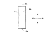
- FIG. 1 shows a process for creating an end structure of a paper product according to the first embodiment.
- FIG. 2 shows an enlarged plan view of the end structure of the paper product according to the first embodiment before folding.
- FIG. 3A shows a plan view of the end structure of the paper product according to the first embodiment.
- FIG. 3B shows a cross-sectional view taken along line AA of FIG. 3A.
- FIG. 3C shows a BB cross-sectional view of FIG. 3A.
- FIG. 4 shows the enlarged plan view before the bending of the edge part structure of the paper product which concerns on the modification 1 of 1st embodiment.
- FIG. 5 shows the enlarged plan view before the bending of the edge part structure of the paper product which concerns on the modification 2 of 1st embodiment.
- FIG. 6 shows the perspective view which looked at the state which closed the lid of the package which concerns on 2nd embodiment from the front upper direction.
- FIG. 7 shows the perspective view which looked at the state which open
- FIG. 8 shows the top view which looked at the state which closed the lid of the package which concerns on 2nd embodiment from upper direction.
- FIG. 9 shows a blank near the upper wall of the lid among the blanks of the package according to the second embodiment.
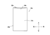
- FIG. 10 shows the perspective view which looked at the state which closed the lid of the package which concerns on 3rd embodiment from the front upper direction.
- FIG. 11 shows the perspective view which looked at the state which open
- FIG. 12 shows the front view which looked at the state which closed the lid of the package which concerns on 3rd embodiment from the front.
- FIG. 13 shows the top view which looked at the state which closed the lid of the package which concerns on 3rd embodiment from upper direction.
- FIG. 14 shows a package blank according to the third embodiment.
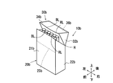
- FIG. 15 shows the perspective view which looked at the state which accommodated the inner box of the package which concerns on 4th embodiment in the outer box from front upper direction.
- FIG. 16 shows the perspective view which looked at the state which slid the inner box of the package which concerns on 4th embodiment from the outer box from the front upper direction.
- FIG. 17 shows the perspective view which looked at the state which took out the inner box of the package which concerns on 4th embodiment from the outer box from the front upper direction.
- FIG. 1 shows a process for creating an end structure of a paper product according to the first embodiment.
- A-1) to (a-4) on the left side of FIG. 1 are plan views of the end portions of the paper product.
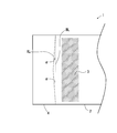
- (B-1) to (b-4) on the right side of FIG. 1 are plan sectional views of the end of the paper product.
- a ruled line RL is processed for the paper product.
- the end structure 1 of the paper product according to the first embodiment is connected to the end 2 and end 2 of the paper product.
- a bent portion 4 which is bent to the side 2 and bonded to the glue margin 3 of the end portion 2, and is provided at a boundary between the end portion 2 and the bent portion 4, and the linear bent line BL and the bent line BL where the bent portion 4 is bent
- a V-shaped ruled line RL that is provided in the vicinity and in the bent portion 4 and that changes in distance from the bent line BL, and has a ruled line RL that is bent when the bent portion 4 is bent.
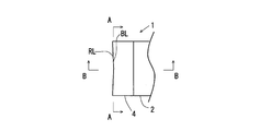
- FIG. 2 shows an enlarged plan view of the end structure of the paper product according to the first embodiment before folding.
- One of the features of the end structure 1 of the paper product according to the first embodiment is that a V-shaped ruled line RL is provided in the vicinity of the linear broken line BL.
- the ruled line RL is for facilitating the folding of the paper product, like a general ruled line.
- the ruled line RL can be constituted by a crease, a perforation, or a thin wall. Examples of the processing of the ruled line RL include existing processing technology, processing by a plotter, and processing by embossing.
- the predetermined angle ⁇ is 1 degree.
- the predetermined angle ⁇ is not limited to this angle.
- the predetermined angle ⁇ can be 0.1 to 5.0 degrees.
- the predetermined angle ⁇ can be 0.2 to 2.0 degrees. More preferably, the predetermined angle ⁇ can be set to 0.5 to 1.0 degree.
- the predetermined angle ⁇ when the predetermined angle ⁇ is reduced, the bending becomes easy at the ruled line RL, and the tensile force is reduced. Further, when the predetermined angle ⁇ is increased, the thickness of the end portion is increased and the shape of the paper product is changed, so that there is a concern about the influence on the paper product. On the other hand, the change in the shape of the paper product can be reduced by reducing the predetermined angle ⁇ . Therefore, the predetermined angle ⁇ can be designed in consideration of the tensile force and the change in the shape of the paper product.
- the ruled line RL may be curved.
- the bent portion 4 is Glued to generation 3.
- the tip of the bent portion 4 is bonded.
- the tensile force can be effectively applied.
- the entire bent portion 4 may be bonded to the end portion 2.
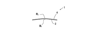
- FIG. 3A shows a plan view of the end structure of the paper product according to the first embodiment.
- FIG. 3B shows a cross-sectional view taken along line AA of FIG. 3A.
- FIG. 3C shows a BB cross-sectional view of FIG. 3A.
- the end structure 1 of the paper product according to the first embodiment is bent at a straight bent line BL and a ruled line RL, and the end 2 and the bent part 4 are folded to form a double structure. Moreover, the end part 2 and the bending part 4 are curving so that the bending part 4 side may swell.
- the paper product is originally bent at the ruled line position, but in the end structure 1 of the paper product according to the first embodiment, the paper product is bent at a broken line BL different from the ruled line RL.
- a restoring force is applied to return the paper product to the original position.
- the bent line 4 is also bent, and the restoring force acts also on the ruled line RL.
- the ruled line RL is formed in a V shape so that the distance from the broken line BL changes.
- the V-shaped ruled line RL is less likely to be bent than when the ruled line RL is formed in a straight line parallel to the broken line. Therefore, when the paper product is bent along the straight broken line BL, the ruled line RL is bent while resisting, so that a stronger restoring force acts. Further, the bent portion 4 is bonded to the end portion 2. As a result, at the end 2 of the paper product, although a stronger restoring force is applied than before, it cannot be restored. Therefore, in the end structure 1 of the paper product according to the first embodiment, a tensile force acts inside the end 2 and the bent portion 4 so that the bent portion 4 side swells.
- the end portion 2 and the bent portion 4 are curved so that the bent portion 4 side swells.
- the end structure 1 of the paper product according to the first embodiment since a tensile force is applied to the inside of the end 2 and the bent portion 4 in advance, the bending of the paper due to deterioration over time can be suppressed. Further, the end structure 1 of the paper product according to the first embodiment has a double structure in which the end portion 2 and the bent portion 4 are folded and further has a very simple configuration, and thus is hardly deteriorated.
- the ruled line RL is close to the polygonal line BL in the vicinity of both ends of the polygonal line BL, and the distance from the polygonal line BL gradually increases toward the center. Therefore, even when the paper product is bent at the ruled line RL, it becomes difficult to stand out, and the change in the shape of the paper product due to the provision of the ruled line RL can be reduced.
- the end structure 1 of the paper product according to the first embodiment is merely an example.
- the ruled line RL may be provided with a V-shaped ruled line RL at the center of the broken line BL as shown in FIG.
- the predetermined angle ⁇ is larger than that in the first embodiment in the example shown in FIG. 4 (modified example 1).
- a larger tensile force can be applied to the inside of the end portion 2 and the bent portion 4.
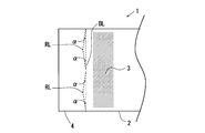
- the ruled line RL may be provided with a plurality of V-shaped ruled lines RL as shown in FIG.
- the predetermined angle ⁇ is larger than that in the first embodiment in the example shown in FIG.
- the example shown in FIG. 5 (modified example 2) has the same V-shaped ruled line as that of the modified example 1.
- the ruled line RL may be provided on the end 2 side.
- the end portion 2 and the bent portion 4 are curved so that the bent portion 4 side swells.
- the end 2 and the bent portion 4 are curved so that the end 2 side swells (the bent portion 4 side is recessed). That is, the direction in which the end portion is inflated (the direction in which it is recessed) can be determined by the position where the ruled line RL is provided. Therefore, the position where the ruled line RL is provided can be changed as appropriate according to the application.
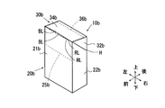
- FIG. 6 is a perspective view of the hinge lid package (hereinafter simply referred to as “package”) according to the second embodiment as viewed from the front upper side with the lid 30a closed.
- FIG. 7 shows the perspective view which looked at the state which open
- FIG. 8 shows the top view which looked at the state which closed the lid of the package which concerns on 2nd embodiment from upper direction.
- the package 10a according to the second embodiment is a so-called hinge-lid box-type package having a substantially rectangular parallelepiped shape.
- the package 10a includes a package main body 20a as an accommodating portion, and a lid 30a as a lid member that is rotatably connected to the package main body 20a via a hinge H.
- the front side of the package 10a is defined as “front” and the back side is defined as “rear” unless otherwise specified.
- the lid side of the package 10a is defined as “upper”, and the opposite side (the bottom side of the package) is defined as “lower”.
- the package body 20a is a box having a shape in which the upper end side of the rectangular parallelepiped shape is cut obliquely.
- the package main body 20a includes a front wall 21a and a rear wall of opposing package main bodies, opposing side walls 22a and 22a, and a lower wall.
- the package body 20a is open at the top so that tobacco products can be taken in and out.
- a hinge H is formed at the upper end of the rear wall of the package body 20a. The hinge H extends between the rear portions of the upper end edges of the side walls 22a, 22a of the package body, and connects the rear wall of the package body and the lid 30a to each other so as to be rotatable.
- the inner frame 40a has a substantially U-shaped front frame and side frames connected to both side edges of the front frame.
- the inner frame 40a is bonded to the inner surface of the package main body 20a, specifically, the front wall 21a of the package main body and the inner surfaces of the side walls 22a and 22a in a state where the inner frame 40a partially protrudes upward from the opening end of the upper portion of the package main body 20a. Has been.
- the lid 30a has a rectangular rear wall connected to the hinge H, a rectangular lid upper wall 34a connected so as to be orthogonal to the lid rear wall, and a lid upper wall 34a orthogonal to the lid 30a. And a rectangular lid front wall 31a connected to each other and a pair of lid side walls 32a, 32a.
- the pair of side walls 32a, 32a has a trapezoidal shape and is connected to the side edges of the rear wall, the upper wall 34a, and the front wall 31a of the lid.
- the package 10a according to the second embodiment uses the end structure 1 of the paper product according to the first embodiment on the front wall 31a of the lid.
- the end portion 2 in the end structure 1 of the paper product corresponds to the front wall 31a of the lid
- the bent portion 4 corresponds to the front wall reinforcing frame 35a of the lid that reinforces the front wall 31a of the lid.
- the lower edge of the lid front wall 31a, that is, the bent portion of the lid front wall reinforcing frame 35a has a fold line BL and a ruled line RL, and the reinforcement frame is bent inward at the fold line BL and the ruled line RL. .
- the front wall 31a of the lid is slightly curved so as to swell rearward.
- FIG. 9 shows a blank near the upper wall of the lid among the blanks of the package according to the second embodiment.
- a front wall panel P1 which is located on the opposite side of the rear wall panel and serves as the front wall 31a of the lid is connected to the upper edge of the upper wall panel constituting the upper wall 34a of the lid.
- a front wall reinforcing panel P2 constituting the front wall reinforcing frame 35a of the lid is further connected to the upper edge of the front wall panel P1.
- the front wall reinforcing panel P2 is bent inwardly along the broken line BL and the ruled line RL, and is superimposed on the front wall panel P1 and bonded to thereby reinforce the front wall 31a of the lid.
- side wall panels P3, which are the side walls 32a of the lid, are connected to both side edges of the front wall panel P1.
- the panel located under the side wall panel P3 is an inner top flap P4 that is superimposed on the upper wall panel and reinforces the upper wall of the lid.
- the end structure 1 of the paper product according to the first embodiment is used for the front wall 31a of the lid, and the front wall 31a of the lid and the front wall reinforcing panel 35a of the lid are arranged rearward. Slightly curved to swell. That is, a tensile force is applied to the front wall 31a of the lid and the front wall reinforcing panel 35a of the lid so that the front wall 31a of the lid swells rearward. As a result, it is possible to suppress paper bending due to deterioration over time.
- the front wall 31a of the lid and the front wall reinforcing panel 35a of the lid are folded and have a double structure, and since it has a very simple configuration, it is difficult to deteriorate. Further, the lid front wall 31a and the lid front wall reinforcing panel 35a are slightly curved so as to swell rearward and are in close contact with the inner frame 40a, thereby improving lid closure. Further, since a gap is not easily formed between the lid 30a and the opening of the package body 20a, it is difficult to spill tobacco products, for example, cigarettes.
- FIG. 10 shows the perspective view which looked at the state which closed the lid of the package which concerns on 3rd embodiment from the front upper direction.
- FIG. 11 shows the perspective view which looked at the state which open
- FIG. 12 shows the front view which looked at the state which closed the lid of the package which concerns on 3rd embodiment from the front.
- FIG. 13 shows the top view which looked at the state which closed the lid of the package which concerns on 3rd embodiment from upper direction.
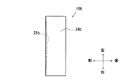
- the package 10b according to the third embodiment is a so-called hinge-lid box-type package having a substantially rectangular parallelepiped shape.
- the package 10b according to the third embodiment is similar to the package 10a according to the second embodiment, as a package main body 20b as an accommodating portion, and as a lid member that is rotatably connected to the package main body 20b via a hinge H.
- the lid 30b is configured to be included.
- the front wall of the package 10b according to the third embodiment is entirely constituted by the front wall 21b of the package body. Therefore, the lid 30b is configured by the upper wall 34b of the lid, the side walls 32b and 32b of the lid, and the rear wall of the lid, and does not include the front wall of the lid.
- the package 10b according to the third embodiment is configured not to include an inner frame.
- symbol is for distinguishing embodiment, and when the number is the same, it shall have the same function except the case where it mentions especially. The same applies to the description of other embodiments.
- the package 10b according to the third embodiment as described above is between the lid 30b and the package body 20b, more specifically, between the front edge of the upper wall 34b of the lid and the upper edge of the front wall 21b of the package body.
- a gap is likely to occur in Therefore, in the package 10b according to the third embodiment, the end structure 1 of the paper product according to the first embodiment is used for each of the upper wall 34b of the lid and the front wall 21b of the package body.
- the end 2 of the end structure 1 of the paper product corresponds to the upper wall 34b of the lid
- the bent portion 4 corresponds to the upper wall reinforcing frame 36b of the lid that reinforces the upper wall 34b of the lid. .
- the front edge of the upper wall 34b of the lid that is, the bent portion of the upper wall reinforcing frame 36b of the lid has a fold line BL and a ruled line RL, and the upper wall reinforcing frame 36b of the lid has an inner side at the fold line BL and the ruled line RL. Is bent.
- the end 2 of the paper product end structure 1 corresponds to the front wall 21b of the package main body, and the bent portion 4 reinforces the front wall 21b of the package main body. It corresponds to the reinforcing frame 25b.
- the upper edge of the front wall 21b of the package body that is, the bent portion of the front wall reinforcement frame 25b of the package body has a fold line BL and a ruled line RL, and the front wall reinforcement frame 25b of the package body has a fold line BL and a ruled line. It is bent inward by RL.
- the upper wall 34b of the lid is slightly curved so as to bulge downward.
- the front wall 21b of the package body is slightly curved so as to swell rearward.
- FIG. 14 shows a blank of the package according to the third embodiment.
- the first blank B1 has a main body area R1 that becomes the package main body 20b and a lid area R2 that becomes the lid 30b.
- the main body section R1 has a front wall panel P5 of the main body that becomes the front wall 21b of the package main body.
- a front wall reinforcing panel P6 of the main body that becomes the front wall reinforcing frame 25b of the package main body is connected to the lower edge of the front wall panel P5 of the main body.
- the front wall reinforcing panel P6 of the main body is bent at the fold line BL and the ruled line RL, and is overlapped and bonded to the front wall panel P5 of the main body, thereby reinforcing the front wall of the package main body. Further, the side wall panels P7 and P7 of the main body that become the side wall 22b of the package main body are connected to both side edges of the front wall panel P5 of the main body.
- a lower wall (bottom plate) panel P8 of the main body which is a lower wall of the package main body, is connected to the upper edge of the front wall panel P5 of the main body.
- the lower wall panel P8 of the main body is connected to a rear wall panel P9 of the main body which is located on the opposite side of the front wall panel P5 of the main body and serves as the rear wall of the package main body.
- Inner side flaps P10 and P10 of the main body which become the side walls 22b and 22b of the package main body are connected to both side edges of the rear wall panel P9 of the main body.
- the inner bottom flaps P11 of the main body are connected to the lower edges of the inner side flaps P10, P10 of the main body.
- the inner bottom flap P11 of the main body is overlapped with the lower wall panel P8 of the main body, and the lower wall of the package main body. Reinforce the.
- the lid section R2 has a rear wall panel P12 of the lid serving as the rear wall of the lid, and the lower edge of the rear wall panel P12 of the lid is connected to the body of the body section R1 via a hinge line L1 serving as the hinge H. It is connected to the rear wall panel P9. Further, the upper wall panel P13 of the lid, which becomes the upper wall 34b of the lid, is connected to the upper edge of the rear wall panel P12 of the lid. On both edges of the upper wall panel P13 of the lid, side wall panels P14 and P14 of the lid that become the side walls 32b and 32b of the lid are connected.
- inner side flaps P15 of the lid which are part of the side walls 32b, 32b of the lid, are connected to both side edges of the rear wall panel P12 of the lid.
- the lid inner side flap P15 is overlapped with the lid side wall panel P14 to reinforce the lid side wall 32b.
- an inner top flap P16 of the lid constituting the upper wall reinforcing frame 36b of the lid is connected to the upper edge of the upper wall panel P13 of the lid.
- the inner top flap P16 of the lid is bent at the broken line BL and the ruled line RL, and is overlapped with and bonded to the upper wall panel P13 of the lid, thereby reinforcing the upper wall 34b of the lid.
- the end structure 1 of the paper product according to the first embodiment is used for the upper wall 34b of the lid, and the upper wall 34b of the lid and the upper wall reinforcing frame 36b of the lid are arranged downward. Slightly curved to swell. That is, a tensile force acts on the inside of the upper wall 34b of the lid and the upper wall reinforcing frame 36b of the lid so that the upper wall 34b of the lid and the upper wall reinforcing frame 36b of the lid swell downward. As a result, it is possible to suppress paper bending due to deterioration over time.
- the upper wall 34b of the lid and the upper wall reinforcing frame 36b of the lid are folded and have a double structure, and further, since it has a very simple configuration, it is difficult to deteriorate.
- the end structure 1 of the paper product according to the first embodiment is used for the front wall 21b of the package body, and the front wall 21b of the package body and the front wall reinforcing frame of the package body are used.
- 25b is slightly curved so as to swell rearward. That is, a tensile force acts on the inside of the front wall 21b of the package body and the front wall reinforcement frame 25b of the package body so that the front wall 21b of the package body and the front wall reinforcement frame 25b of the package body swell rearward. Yes.
- the front wall 21b of the package body and the front wall reinforcement frame 25b of the package body are folded and have a double structure and a very simple configuration, they are hardly deteriorated.
- the upper wall 34b of the lid and the upper wall reinforcing frame 36b of the lid are curved so as to swell downward, and the front wall 21b of the package body and the front wall reinforcing frame 25b of the package body are curved so as to swell rearward, It is difficult for a gap to be formed between the lid 30b and the opening of the package body 20b. As a result, tobacco products such as cigarettes can be prevented from spilling outside.
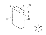
- FIG. 15 shows the perspective view which looked at the state which accommodated the inner box of the package which concerns on 4th embodiment in the outer box from front upper direction.
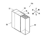
- FIG. 16 shows the perspective view which looked at the state which slid the inner box of the package which concerns on 4th embodiment from the outer box from the front upper direction.
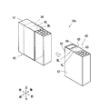
- FIG. 17 shows the perspective view which looked at the state which took out the inner box of the package which concerns on 4th embodiment from the outer box from the front upper direction.
- the package 10c according to the fourth embodiment has an outer box 50 having a substantially rectangular parallelepiped shape having an opening on the right side, and is accommodated in the outer box 50, houses a cigarette as a tobacco product, and takes out the cigarette from the upper opening. And an inner box 60 having a substantially rectangular parallelepiped shape.
- the end structure 1 of the paper product according to the first embodiment is used for the upper wall 51 of the outer box.
- the end portion 2 of the end structure 1 of the paper product corresponds to the upper wall 51 of the outer box
- the bent portion 4 corresponds to the upper wall reinforcement frame 56 of the outer box that reinforces the upper wall 51 of the outer box.
- the right side edge of the upper wall 51 of the outer box that is, the bent portion of the upper wall reinforcing frame 56 of the outer box, has a broken line BL and a ruled line RL
- the upper wall reinforcing frame 56 of the outer box has a bent line BL and a ruled line. It is bent inward by RL.
- the upper wall 51 of the outer box is slightly curved so as to swell downward.
- the package 10c according to the fourth embodiment is continuous with the upper edge of the side wall 62 (left side) of the inner box, the left upper edge of the front wall 61 of the inner box, and the rear wall of the inner box.
- the upper wall 65 of the inner box connected to the upper left edge of 63 is provided.
- the upper wall 65 of the inner box is connected to an upper wall reinforcing frame 66 of the inner box that is bent outward to reinforce the upper wall 65 of the inner box.
- the edge part structure 1 of the paper product which concerns on 1st embodiment is used for the upper wall 65 of an inner box.
- the upper wall 65 of the inner box is used so that the end structure 1 of the paper product according to the first embodiment is in the reverse direction, that is, the bent portion 4 is bent outward. ing.
- the end portion 2 of the end structure 1 of the paper product corresponds to the upper wall 65 of the inner box, and the bent portion 4 is located outside the upper wall 65 of the inner box and reinforces the upper wall of the inner box. This corresponds to the upper wall reinforcing frame 66 of the upper wall.
- a bent line BL and a ruled line RL exist at the right edge of the upper wall 65 of the inner box, that is, a bent portion of the upper wall reinforcing frame 66 of the inner box, and the upper wall reinforcing frame 66 of the inner box has a bent line BL and a ruled line RL. It is bent outward. As a result, as shown in FIG. 17, the upper wall 65 of the inner box is slightly curved so as to bulge upward.
- the end structure 1 of the paper product according to the first embodiment is used for the upper wall 51 of the outer box, and the upper wall 51 of the outer box and the upper wall reinforcing frame 56 of the outer box are It is slightly curved so as to swell downward. That is, a tensile force acts on the inside of the upper wall 51 of the outer box and the upper wall reinforcing frame 56 of the outer box so that the upper wall 51 of the outer box and the upper wall reinforcing frame 66 of the outer box swell downward. Yes. As a result, it is possible to suppress paper bending due to deterioration over time.
- the upper wall 51 of the outer box and the upper wall reinforcing frame 66 of the outer box are folded and have a double structure and a very simple configuration, it is difficult to deteriorate. Further, since the upper wall 51 of the outer box and the upper wall reinforcing frame 56 of the outer box are curved so as to swell downward, a gap is hardly generated between the opening of the outer box 50 and the inner box 60. As a result, tobacco products such as cigarettes can be prevented from spilling outside.
- the end structure 1 of the paper product according to the first embodiment may also be used on the side wall 62 (right side) of the inner box. By slightly curving the side wall 62 (right side) of the inner box so as to bulge to the left side, a gap is less likely to occur between the opening of the outer box 50 and the inner box 60.
- the edge part structure 1 of the paper product which concerns on 1st embodiment is used for the upper wall 65 of an inner box, and the upper wall 65 of an inner box and the upper wall reinforcement frame of an inner box 66 is slightly curved so as to bulge upward. That is, a tensile force acts on the inner wall upper wall 65 and the inner box upper wall reinforcing frame 66 so that the upper wall 65 of the inner box and the upper wall reinforcing frame 66 of the inner box swell upward. Yes. As a result, it is possible to suppress paper bending due to deterioration over time.
- the upper wall 65 of the inner box and the upper wall reinforcing frame 66 of the inner box are folded and have a double structure and a very simple configuration, it is difficult to deteriorate. Further, the upper wall 65 of the inner box and the upper wall reinforcing frame 66 of the inner box are curved so as to bulge upward, so that the resistance with the inner surface of the upper wall 51 of the outer box is increased. As a result, it is possible to suppress the inner box 60 from falling off the outer box 50.
- the end structure of the paper product and the paper package according to the present invention can be implemented by combining the embodiments as much as possible.
- the package which accommodates tobacco goods for example, a cigarette
- the edge part structure of the paper product which concerns on this invention was mentioned as an application example of the edge part structure of the paper product which concerns on this invention, However, It is not limited to this.
- the end structure of the paper product according to the present invention can be widely applied to packages that contain articles other than tobacco products.
Landscapes
- Engineering & Computer Science (AREA)
- Mechanical Engineering (AREA)
- Cartons (AREA)
- Packaging Of Annular Or Rod-Shaped Articles, Wearing Apparel, Cassettes, Or The Like (AREA)
Priority Applications (6)
| Application Number | Priority Date | Filing Date | Title |
|---|---|---|---|
| CN201480078742.4A CN106458357B (zh) | 2014-05-09 | 2014-05-09 | 纸制品的端部结构以及纸制包装 |
| EP14891448.4A EP3141489B1 (de) | 2014-05-09 | 2014-05-09 | Papierproduktrandstruktur und papierverpackung |
| JP2016517771A JP6165327B2 (ja) | 2014-05-09 | 2014-05-09 | 紙製品の端部構造、及び紙製のパッケージ |
| PCT/JP2014/062443 WO2015170395A1 (ja) | 2014-05-09 | 2014-05-09 | 紙製品の端部構造、及び紙製のパッケージ |
| KR1020167031208A KR101943723B1 (ko) | 2014-05-09 | 2014-05-09 | 종이 제품의 단부 구조 및 종이제의 패키지 |
| RU2016148205A RU2647379C1 (ru) | 2014-05-09 | 2014-05-09 | Структура концевого участка бумажного изделия и упаковка, изготовленная из бумаги |
Applications Claiming Priority (1)
| Application Number | Priority Date | Filing Date | Title |
|---|---|---|---|
| PCT/JP2014/062443 WO2015170395A1 (ja) | 2014-05-09 | 2014-05-09 | 紙製品の端部構造、及び紙製のパッケージ |
Publications (1)
| Publication Number | Publication Date |
|---|---|
| WO2015170395A1 true WO2015170395A1 (ja) | 2015-11-12 |
Family
ID=54392263
Family Applications (1)
| Application Number | Title | Priority Date | Filing Date |
|---|---|---|---|
| PCT/JP2014/062443 WO2015170395A1 (ja) | 2014-05-09 | 2014-05-09 | 紙製品の端部構造、及び紙製のパッケージ |
Country Status (6)
| Country | Link |
|---|---|
| EP (1) | EP3141489B1 (de) |
| JP (1) | JP6165327B2 (de) |
| KR (1) | KR101943723B1 (de) |
| CN (1) | CN106458357B (de) |
| RU (1) | RU2647379C1 (de) |
| WO (1) | WO2015170395A1 (de) |
Families Citing this family (2)
| Publication number | Priority date | Publication date | Assignee | Title |
|---|---|---|---|---|
| CN110191735A (zh) | 2016-12-12 | 2019-08-30 | Vmr产品有限责任公司 | 蒸发器 |
| DE102021118906A1 (de) | 2021-07-21 | 2023-01-26 | Focke & Co. (Gmbh & Co. Kg) | Packung für Produkte der Zigarettenindustrie |
Citations (5)
| Publication number | Priority date | Publication date | Assignee | Title |
|---|---|---|---|---|
| JP2005096780A (ja) * | 2003-09-22 | 2005-04-14 | Plus Stationery Corp | 物品収容ケースなどの樹脂製シート組立て物品における構成シートの補強装置 |
| JP4186103B2 (ja) * | 2002-11-11 | 2008-11-26 | 第一大宮株式会社 | 物品搬送用箱 |
| JP2011068411A (ja) * | 2009-09-17 | 2011-04-07 | G D Spa | 摺動開口型のたばこ製品のパッケージおよび関連する製造方法 |
| JP2011516359A (ja) * | 2008-04-14 | 2011-05-26 | ブリティッシュ アメリカン タバコ (インヴェストメンツ) リミテッド | 喫煙品用パッケージ |
| WO2012025233A1 (de) * | 2010-08-27 | 2012-03-01 | Sigismund Laskowski | Wiederverschliessbare faltschachtel und ihr zuschnitt |
Family Cites Families (11)
| Publication number | Priority date | Publication date | Assignee | Title |
|---|---|---|---|---|
| NL9301925A (nl) * | 1993-11-05 | 1995-06-01 | Martin Gerhard Weber Caspers | Doosvormige verpakking met strooiopening en een plano ter vervaardiging daarvan. |
| DE19938167A1 (de) * | 1999-08-16 | 2001-02-22 | Focke & Co | Klappschachtel für Zigaretten |
| ITBO20010748A1 (it) | 2001-12-11 | 2003-06-11 | Gd Spa | Contenitore rigido per articoli da fumo |
| DE10314375A1 (de) | 2003-03-28 | 2004-10-07 | Focke & Co.(Gmbh & Co. Kg) | Klappschachtel für Zigaretten |
| JP2006248233A (ja) * | 2006-04-04 | 2006-09-21 | Mitsubishi Plastics Ind Ltd | 折り曲げ罫線入りプラスチックシート |
| CN101842174A (zh) * | 2007-09-22 | 2010-09-22 | 工业折纸公司 | 用二维板形材料形成的铰链式三维结构 |
| JP5323399B2 (ja) | 2008-06-06 | 2013-10-23 | 日本たばこ産業株式会社 | スライド機能付きヒンジリッド型パッケージ |
| CN201604848U (zh) * | 2010-03-05 | 2010-10-13 | 红塔烟草(集团)有限责任公司 | 新型凸翻盖卷烟盒 |
| CN103502104A (zh) * | 2011-02-09 | 2014-01-08 | 米德韦斯特瓦科包装系统有限责任公司 | 折叠阻力减少机构 |
| RU2600918C2 (ru) * | 2011-11-21 | 2016-10-27 | Филип Моррис Продактс С.А. | Емкость с шарнирной крышкой |
| DE102012018759B4 (de) * | 2012-09-24 | 2020-09-17 | Thimm Verpackung Gmbh + Co. Kg | Verpackung |
-
2014
- 2014-05-09 WO PCT/JP2014/062443 patent/WO2015170395A1/ja active Application Filing
- 2014-05-09 KR KR1020167031208A patent/KR101943723B1/ko active IP Right Grant
- 2014-05-09 EP EP14891448.4A patent/EP3141489B1/de active Active
- 2014-05-09 RU RU2016148205A patent/RU2647379C1/ru active
- 2014-05-09 JP JP2016517771A patent/JP6165327B2/ja active Active
- 2014-05-09 CN CN201480078742.4A patent/CN106458357B/zh active Active
Patent Citations (5)
| Publication number | Priority date | Publication date | Assignee | Title |
|---|---|---|---|---|
| JP4186103B2 (ja) * | 2002-11-11 | 2008-11-26 | 第一大宮株式会社 | 物品搬送用箱 |
| JP2005096780A (ja) * | 2003-09-22 | 2005-04-14 | Plus Stationery Corp | 物品収容ケースなどの樹脂製シート組立て物品における構成シートの補強装置 |
| JP2011516359A (ja) * | 2008-04-14 | 2011-05-26 | ブリティッシュ アメリカン タバコ (インヴェストメンツ) リミテッド | 喫煙品用パッケージ |
| JP2011068411A (ja) * | 2009-09-17 | 2011-04-07 | G D Spa | 摺動開口型のたばこ製品のパッケージおよび関連する製造方法 |
| WO2012025233A1 (de) * | 2010-08-27 | 2012-03-01 | Sigismund Laskowski | Wiederverschliessbare faltschachtel und ihr zuschnitt |
Non-Patent Citations (1)
| Title |
|---|
| See also references of EP3141489A4 * |
Also Published As
| Publication number | Publication date |
|---|---|
| KR20160143780A (ko) | 2016-12-14 |
| CN106458357B (zh) | 2018-05-29 |
| JP6165327B2 (ja) | 2017-07-19 |
| RU2647379C1 (ru) | 2018-03-15 |
| EP3141489A4 (de) | 2018-01-17 |
| JPWO2015170395A1 (ja) | 2017-04-20 |
| EP3141489B1 (de) | 2019-04-17 |
| CN106458357A (zh) | 2017-02-22 |
| KR101943723B1 (ko) | 2019-01-29 |
| EP3141489A1 (de) | 2017-03-15 |
Similar Documents
| Publication | Publication Date | Title |
|---|---|---|
| JP4750129B2 (ja) | 閉鎖及び/又は開放の可聴指示を備えた側面開放ヒンジ蓋容器 | |
| CN107000889B (zh) | 具有盖提升件的肩状包 | |
| KR20110002481A (ko) | 슬라이드 작용형 힌지 리드 패키지 | |
| JP2011098735A (ja) | ヒンジリッド型パッケージ | |
| KR20210118433A (ko) | 이중 힌지식 뚜껑을 가진 흡연 물품용 강성 팩 및 상기 흡연 물품용 강성 팩을 제조하기 위한 블랭크 | |
| KR102520340B1 (ko) | 폐쇄 플랩을 구비한 접근 개구부를 포함하는 패키지 | |
| US20180346234A1 (en) | Pack for consumer goods | |
| CN108602613B (zh) | 铰接盖容器和坯料 | |
| JP5077563B2 (ja) | ヒンジリッド型パッケージ | |
| JP6165327B2 (ja) | 紙製品の端部構造、及び紙製のパッケージ | |
| RU2689858C2 (ru) | Контейнер, содержащий внутренний каркас с расположенной с зазором задней стенкой, соответствующий внутренний каркас и рулон | |
| JP3226018U (ja) | 喫煙品用パッケージ | |
| JP2009292513A (ja) | 包装容器 | |
| EP3040292A1 (de) | Klappdeckelbehälter mit konvergierenden Scharnierkanten | |
| US20190092560A1 (en) | Container with top curved bevelled edge | |
| US9896261B2 (en) | Container for consumer articles with in depth inner frame | |
| TWI535636B (zh) | 紙製品之端部構造,及紙製包裝盒 | |
| EP1927551A1 (de) | Behälter und Zuschnitte | |
| JP6160161B2 (ja) | 包装容器 | |
| JP5859655B2 (ja) | ヒンジリッド型ボックス | |
| TWI483873B (zh) | 滑箱型包裝件 | |
| JP6291067B2 (ja) | パッケージ | |
| WO2018130556A1 (en) | Container with front spacer element | |
| JP2014111478A (ja) | 煙草製品のための箱 | |
| JP2014111479A (ja) | 煙草製品のための箱 |
Legal Events
| Date | Code | Title | Description |
|---|---|---|---|
| 121 | Ep: the epo has been informed by wipo that ep was designated in this application |
Ref document number: 14891448 Country of ref document: EP Kind code of ref document: A1 |
|
| ENP | Entry into the national phase |
Ref document number: 2016517771 Country of ref document: JP Kind code of ref document: A |
|
| ENP | Entry into the national phase |
Ref document number: 20167031208 Country of ref document: KR Kind code of ref document: A |
|
| NENP | Non-entry into the national phase |
Ref country code: DE |
|
| ENP | Entry into the national phase |
Ref document number: 2016148205 Country of ref document: RU Kind code of ref document: A |
|
| REEP | Request for entry into the european phase |
Ref document number: 2014891448 Country of ref document: EP |
|
| WWE | Wipo information: entry into national phase |
Ref document number: 2014891448 Country of ref document: EP |