WO2015166958A1 - 情報処理装置および情報処理装置の制御方法 - Google Patents
情報処理装置および情報処理装置の制御方法 Download PDFInfo
- Publication number
- WO2015166958A1 WO2015166958A1 PCT/JP2015/062871 JP2015062871W WO2015166958A1 WO 2015166958 A1 WO2015166958 A1 WO 2015166958A1 JP 2015062871 W JP2015062871 W JP 2015062871W WO 2015166958 A1 WO2015166958 A1 WO 2015166958A1
- Authority
- WO
- WIPO (PCT)
- Prior art keywords
- value
- sensor
- contact sensor
- contact
- reference level
- Prior art date
- Legal status (The legal status is an assumption and is not a legal conclusion. Google has not performed a legal analysis and makes no representation as to the accuracy of the status listed.)
- Ceased
Links
Images













Classifications
-
- H—ELECTRICITY
- H04—ELECTRIC COMMUNICATION TECHNIQUE
- H04M—TELEPHONIC COMMUNICATION
- H04M1/00—Substation equipment, e.g. for use by subscribers
Definitions
- the present invention relates to an information processing apparatus capable of executing a predetermined process in accordance with a detection result of a contact sensor.
- FIG. 15 is a graph showing calibration of a conventional reference level value.
- the reference level value of the contact sensor is calibrated according to the physical quantity value (contact sensor output value) acquired at regular intervals, and the threshold value of the contact sensor is changed according to the calibrated reference level value. It was.
- the conventional technology has a problem that malfunction of the contact sensor cannot be sufficiently prevented.
- FIG. 16 is a diagram for explaining a case where the contact sensor continues to react when foreign matter (water or the like) adheres to the vicinity of the electrode of the contact sensor.
- the output value of the contact sensor becomes small and falls below the threshold value of the contact sensor (the gripping threshold value and the release threshold value).
- the gripping threshold value and the release threshold value the threshold value of the contact sensor.
- the present invention has been made in view of the above-described conventional problems, and its purpose is to allow a user to be aware of an abnormal state even when a foreign object (such as water) adheres to the vicinity of an electrode of a contact sensor.
- the present invention provides an information processing apparatus including a contact sensor that can be used and can sufficiently prevent malfunction, and a method for controlling the information processing apparatus.
- the information processing apparatus determines contact with the electrode of the user's hand via an electrode provided at a position where the user's hand holding the gripping unit contacts.
- An information processing apparatus including a contact sensor comprising: a reference level value setting calibration unit having a function of calibrating the reference level value of the contact sensor by performing an operation in which the user grasps and releases the electrode with a hand.
- the reference level value setting calibration unit may calculate a reference level value of the contact sensor having a constant value based on an output value output from the contact sensor or a plurality of output values output from the contact sensor.
- a function of setting and calibrating the reference level value of the contact sensor when the output value output from the contact sensor becomes a value determined that the user's hand has touched the electrode When the difference between the maximum value and the minimum value of the output value of the contact sensor is greater than or equal to a predetermined value during the operation in which the user grasps and releases the electrode by hand, the contact sensor outputs
- the reference level value of the contact sensor is calibrated based on the output value or a plurality of output values output from the contact sensor, and the contact sensor is set based on the reference level value of the calibrated contact sensor. Whether or not the user's hand touches the electrode is determined based on a threshold value.
- the control method for the information processing apparatus makes contact with the electrode of the user's hand via an electrode provided at a position where the user's hand holding the gripping unit contacts.
- a method of controlling an information processing apparatus including a contact sensor for determining whether the output value is a constant value based on an output value output from the contact sensor or a plurality of output values output from the contact sensor.
- the difference between the second step of enabling the function of calibrating the level value and the maximum value and the minimum value of the output value of the contact sensor during the operation in which the user grasps and releases the electrode with a hand is a predetermined value or more. so A third step of calibrating a reference level value of the contact sensor based on an output value output from the contact sensor or a plurality of output values output from the contact sensor; And a fourth step of determining whether or not the user's hand touches the electrode based on a threshold value of the contact sensor set based on a reference level value of the contact sensor.
- the present invention has been made in view of the above-described conventional problems, and an object thereof is information provided with a contact sensor that can be used without the user being aware of an abnormal state and can sufficiently prevent malfunction.
- a control method for the processing apparatus and the information processing apparatus can be realized.
- FIG. 6 is a diagram for explaining calibration of a reference level value according to the first embodiment.
- 5 is a flowchart for explaining calibration of a reference level value according to the first embodiment.
- FIG. 10 is a diagram for explaining calibration of a reference level value according to the second embodiment. 10 is a flowchart for explaining calibration of a reference level value according to the second embodiment.
- FIG. 10 is a diagram for explaining reference level value calibration according to the third embodiment. 10 is a flowchart for explaining calibration of a reference level value according to the third embodiment.
- FIG. 10 is a diagram for explaining calibration of a reference level value according to a fourth embodiment. 10 is a flowchart for explaining calibration of a reference level value according to the fourth embodiment.
- FIG. 10 is a diagram for explaining reference level value calibration according to the fifth embodiment. 10 is a flowchart for explaining calibration of a reference level value according to the fifth embodiment.
- FIG. 10 is a diagram for explaining calibration of a reference level value according to the sixth embodiment.
- 14 is a flowchart for explaining calibration of a reference level value according to the sixth embodiment. It is a graph which shows the calibration of the conventional reference level value. It is a figure for demonstrating the case where a foreign material adheres to the electrode vicinity of a contact sensor.
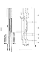
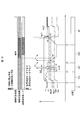
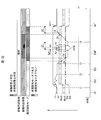
- Timing chart which shows the calibration process of the reference
- a portable terminal is taken as an example of an information processing apparatus, and a case of a portable terminal is taken as an example of a gripping portion.
- the present invention is not limited to this, and has a portion that a person grips.
- the present invention can be applied to any device.
- the information processing device include a smartphone, a mobile phone, a tablet terminal, a remote controller, a dryer, a vacuum cleaner, and other information processing devices operated with a handle.
- the information processing apparatus performs processing according to the presence or absence of gripping.
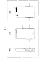
- FIG. 2 is a schematic diagram illustrating an appearance of the mobile terminal (information processing apparatus) 1 according to the present embodiment.
- the mobile terminal 1 includes a display unit 10 (such as a touch panel) on at least one surface of the housing. Note that the surface provided with the display unit 10 is referred to as the “front” of the mobile terminal 1.
- the mobile terminal 1 includes a contact sensor 11 at a position where a user's hand holding the casing of the mobile terminal 1 contacts the mobile terminal 1. For example, as illustrated in FIG. 2, the mobile terminal 1 is in contact with two surfaces adjacent to the long side of the front (the two surfaces are referred to as “side surfaces” of the mobile terminal 1). A sensor 11 is provided.
- the number of contact sensors 11 and the range in which the contact sensors 11 are arranged are not limited to the example shown in FIG. 2.
- a plurality of contact sensors 11 may be arranged on each side surface.
- the contact sensor 11 may be disposed on the entire side surface.
- the contact sensor 11 may be exposed to the outside of the casing or may be disposed in the casing. In other words, the contact sensor 11 should just be provided in the position corresponding to the position of the user's hand holding the housing (gripping part).
- FIG. 1 is a block diagram illustrating an example of a main configuration of the mobile terminal 1.
- the mobile terminal 1 includes a contact sensor 11, a grip determination unit 12 (grip determination device), and a host control unit 13.
- a contact sensor 11 a contact sensor 11
- a grip determination unit 12 grip determination device
- a host control unit 13 a host control unit 13.
- some arrows are omitted in consideration of the visibility of the drawing.
- the contact sensor 11 is a sensor that detects contact of an object such as a user's hand.
- the contact sensor 11 is a capacitance sensor, but is not limited to this example.
- a pressure sensor, an optical sensor, or the like can be used as the contact sensor 11, a pressure sensor, an optical sensor, or the like.
- the capacitance sensor can detect the proximity of the hand (contact between the housing and the hand) even if the housing is interposed between the capacitance sensor and the user's hand.
- the contact sensor 11 outputs an output value (sensor value, physical quantity value) of the sensor according to the presence / absence of an object contact to the grip determination unit 12 based on an instruction from the grip determination unit 12.
- the contact sensor 11 outputs an output value of the sensor corresponding to a change in electrostatic capacitance of an electrode disposed on the side surface of the housing to the grip determination unit 12.
- the potential of the output signal of the contact sensor 11 is used as the output value of the sensor, whether the potential decreases or increases when the housing is gripped depends on the type of the contact sensor.
- the direction in which the output value of the sensor changes as the casing is gripped is defined as the negative direction. That is, the output value of the sensor when the casing is gripped is smaller than the output value of the sensor when the casing is not gripped.
- the host control unit 13 is mainly responsible for control on the host side of the mobile terminal 1. For example, the host control unit 13 controls the display unit 10. The host control unit 13 changes the display of the display unit 10 according to the determination result of the presence / absence of gripping in the gripping determination unit 12.
- the grip determination unit 12 includes a sensor control unit 21, a contact determination unit 22, and a reference level value setting calibration unit 23.
- the grip determination unit 12 includes a storage unit (not shown).
- the storage unit stores a reference level value (reference value), a gripping threshold value, a release threshold value, and the like. Each unit of the grip determination unit 12 can read and write these stored values from the storage unit.
- the reference level value is for representing the output value of the sensor when the casing is not gripped by the user.
- the gripping threshold value is a threshold value for determining that the housing is gripped.
- the release threshold value is a threshold value for determining that the hand is released from the grip (the hand is released). For example, the gripping threshold value is set to a value smaller than the reference level value.
- the release threshold value is set to a value smaller than the reference level value and larger than the grip threshold value.
- the difference between the reference level value and the grasping threshold and the difference between the reference level value and the release threshold are set in advance. That is, when the reference level value is determined, the gripping threshold value and the release threshold value are naturally determined accordingly.
- the reference level value is a variable that can be changed in order to provide a reference (gripping threshold value, release threshold value) for determining the presence or absence of gripping.
- a reference gripping threshold value, release threshold value
- the gripping threshold value and the release threshold value may be set to different values.
- the sensor control unit 21 operates the contact sensor 11 at a predetermined timing, and acquires the output value of the sensor as the output of the contact sensor 11.
- the sensor control unit 21 acquires the output value of the sensor from the contact sensor 11 at regular intervals.
- the sensor control unit 21 acquires the output values of the sensors from the respective contact sensors 11 at regular intervals.
- the sensor control unit 21 outputs the acquired sensor output value to the contact determination unit 22.
- the contact determination unit 22 compares the output value of the sensor with the gripping threshold value. When the output value of the sensor becomes smaller than the gripping threshold value, the user's hand contacts the electrode of the contact sensor 11 (through the housing). It is determined that Moreover, the contact determination part 22 memorize
- the contact determination unit 22 determines that the user's hand is holding the casing (the portable terminal 1) when a plurality of (both sides) contact sensors 11 are in contact. For example, when only the contact sensor 11 on one side is in contact and the contact sensor 11 on the other side is in a non-contact state, the contact determination unit 22 determines that the user's hand is not gripping the housing. Also good. When there is only one contact sensor 11 provided in the mobile terminal 1, the contact determination unit 22 determines the presence or absence of gripping based on the contact state of the contact sensor 11. The contact determination unit 22 outputs determination result information regarding the presence or absence of gripping to the host control unit 13.
- the reference level value setting calibration unit 23 acquires the output value of the sensor from the sensor control unit 21 at a predetermined timing, and sets and calibrates the reference level value based on the output value of the sensor.
- the reference level value setting calibration unit 23 calibrates the reference level value during the predetermined period (first period) when a predetermined condition is satisfied. Further, the reference level value setting calibration unit 23 newly sets the reference level value when the mobile terminal 1 is turned on or when the grip determination function is turned on.
- the reference level value setting calibration unit 23 may acquire the output value of the sensor a plurality of times, and may set an average value (or intermediate value) of the output values of the plurality of sensors as the reference level value.
- the reference level value may be set based on the value.
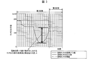
- FIG. 3 is a diagram for explaining the calibration of the reference level value of the present embodiment performed by the reference level value setting calibration unit 23 provided in the portable terminal 1.
- the reference level value setting calibration unit 23 is configured to newly set the reference level value of the contact sensor every first period as in the prior art. As described above, when the reference level value is changed for each first period, the threshold values of the contact sensor (gripping threshold value and release threshold value) are also changed accordingly. A reference level value for representing the output value of the sensor can be set. However, if foreign matter (such as water) adheres to the vicinity of the contact sensor electrode, the output value of the contact sensor becomes smaller and falls below the threshold of the contact sensor, so that foreign matter (such as water) is removed. Or, until the next calibration is performed, it is determined that the user's hand is actually touching the electrode of the contact sensor even though the user's hand is not touching the electrode of the contact sensor. Period may last.
- the reference level value setting calibration unit 23 can calibrate the reference level value of the contact sensor even during the first period. That is, the reference level value setting calibration unit 23 has a function that allows the user to calibrate the reference level value of the contact sensor by performing an operation of grasping and releasing the electrode by hand.
- the reference level value setting calibration unit 23 may select (i) an output value output from the contact sensor at a timing when the first period starts, or (ii) a plurality of the contact sensors in a period before the second period.
- the reference level value of the contact sensor for the first period having a constant value is set based on the output value of the user, and the output value output from the contact sensor indicates that the user's hand has contacted the electrode.
- the function for calibrating the reference level value of the contact sensor when the determined value is reached is made effective.
- the reference level value setting calibration unit 23 is configured such that the difference between the maximum value and the minimum value of the output value of the contact sensor during the operation in which the user grasps and releases the electrode by hand is equal to or greater than a predetermined value.
- the reference level value of the contact sensor having a constant value in the second period, which is a part of the first period, is output from the contact sensor at the timing when the second period starts (iii) Calibration is performed based on an output value or (iv) a plurality of output values of the contact sensor in a period prior to the second period.
- the first period by determining whether the difference between the highest value and the lowest value of the output value of the contact sensor during an operation in which the user grasps and releases the electrode by hand is equal to or greater than a predetermined value, It is determined whether the reference level value of the contact sensor is an appropriate value.
- the contact sensor electrode of the user's hand is applied to the electrode of the contact sensor according to the threshold value of the contact sensor in the second period set based on the reference level value of the contact sensor in the second period. The presence or absence of contact is determined.
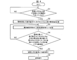
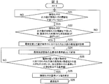
- FIG. 4 is a flowchart for explaining the calibration of the reference level value of the present embodiment.
- step (S1) of determining whether the value is below the threshold value of the contact sensor is performed.
- the function of calibrating the reference level value of the contact sensor in the reference level value setting calibration unit 23 is enabled.
- step (S2) which memorize
- step (S3) of storing the increased value after storing the minimum value as the maximum value is performed.
- step (S4) of judging is performed.
- A is larger than B
- the process proceeds to a step (S5) of calibrating the reference level value of the contact sensor, and after calibrating the reference level value of the contact sensor, the process proceeds to a step (S6) of performing a normal operation.
- the normal operation refers to an operation in a state where the function of calibrating the reference level value of the contact sensor in the reference level value setting calibration unit 23 is disabled.
- A is less than or equal to B, the user continues to search for a new maximum value of the output value of the contact sensor while the user's hand holds and releases the electrode until A becomes greater than B.
- any of the steps (S1) to (S6) may be performed in the reference level value setting calibration unit 23, or only the steps (S5) and (S6) are set for the reference level value.
- the above steps (S1) to (S4) may be performed outside the reference level value setting calibration unit 23.
- the function of calibrating the reference level value of the contact sensor is invalidated in the period following the first period, and the contact sensor The reference level value may not be calibrated. That is, the reference level value of the contact sensor in the second period (the reference level value of the contact sensor after calibration) may be set as the reference level value of the contact sensor in the period subsequent to the first period.
- the reference level value of the contact sensor can be calibrated by the user's hand holding and releasing the electrode. Therefore, it is possible to realize an information processing apparatus that can be used without the user being aware of the abnormal state and can sufficiently prevent malfunction.
- FIG. 5 is a diagram for explaining the calibration of the reference level value of the present embodiment performed by the reference level value setting calibration unit 23 provided in the mobile terminal 1.
- the difference A between the maximum value and the minimum value of the output value of the contact sensor during the operation in which the user grasps and releases the electrode by hand is larger than the reference value B for calibrating the reference level value of the contact sensor.
- the output value of the contact sensor at the timing when the user grasps and releases the electrode with his hand exceeds the threshold (release threshold) of the contact sensor, and the user's hand completely releases the electrode during the first period. This is the case.
- the function of calibrating the reference level value of the contact sensor becomes invalid, the reference level value of the contact sensor in the first period set in advance is not calibrated without calibrating the reference level value of the contact sensor. Maintained.
- the output value of the contact sensor at the timing when the user grasps and releases the electrode with a hand is below the threshold value (release threshold value) of the contact sensor, the reference of the contact sensor as in the first embodiment described above.
- the level value is calibrated.
- FIG. 6 is a flowchart for explaining the calibration of the reference level value of the present embodiment.
- steps (S11) to (S14) in FIG. 6 are the same as steps (S1) to (S4) in FIG. 4 in the first embodiment described above, the description thereof is omitted here.
- step (S14) when A is larger than B, the process proceeds to step (S15) for determining whether the maximum value of the output value of the contact sensor exceeds the threshold value (release threshold value) of the contact sensor.
- the process proceeds to step (S15) for determining whether the maximum value of the output value of the contact sensor exceeds the threshold value (release threshold value) of the contact sensor.
- A is less than or equal to B, the user continues to search for a new maximum value of the output value of the contact sensor while the user's hand holds and releases the electrode until A becomes greater than B.
- step (S15) when it is determined that the maximum value of the output value of the contact sensor exceeds the threshold value (release threshold value) of the contact sensor, the reference level value of the contact sensor is not calibrated and normal operation is performed. It progresses to the step (S17) to perform.
- step (S15) if it is determined in step (S15) that the maximum output value of the contact sensor does not exceed the threshold value (release threshold value) of the contact sensor, the reference level value of the contact sensor is calibrated.
- the process proceeds to (S16), and after the reference level value of the contact sensor is calibrated, the process proceeds to a step (S17) for performing a normal operation.
- the processing level of the information processing apparatus is reduced because the reference level value of the contact sensor is not calibrated. Can be made.
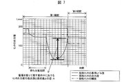
- FIG. 7 is a diagram for explaining the calibration of the reference level value of the present embodiment performed by the reference level value setting calibration unit 23 provided in the mobile terminal 1.
- the reference level value setting calibration unit 23 determines the timing at which the output value output from the contact sensor becomes a value at which it is determined that the user's hand has touched the electrode, A function that enables the reference level value of the contact sensor to be calibrated after a predetermined period (waiting period) after the output value output from the contact sensor falls below the threshold value of the contact sensor is enabled.
- the output value output from the contact sensor falls below the threshold value of the contact sensor, and thus the predetermined period is set.
- the user's input operation to the mobile terminal 1 is distinguished from the operation of the user holding and releasing the electrode by hand for the purpose of calibrating the reference level value of the contact sensor. Can do.
- FIG. 8 is a flowchart for explaining the calibration of the reference level value of the present embodiment.
- Steps (S21), (S23), (S24), and (S25) in FIG. 8 are the same as steps (S1) to (S4) in FIG. Description is omitted.
- step (S21) when the output value output from the contact sensor is a value determined that the user's hand has touched the electrode, the output value output from the contact sensor is the value of the contact sensor. After falling below the threshold, the process proceeds to step (S22) for determining whether the set time (waiting period) has passed.
- the function for calibrating the reference level value of the contact sensor in the reference level value setting calibration unit 23 is enabled, and the user's hand grasps and releases the electrode.
- step S23 the minimum value of the output value of the contact sensor during operation is stored. On the other hand, if the set time (waiting period) has not passed, the reference level value setting calibration unit 23 The function of calibrating the reference level value of the contact sensor remains disabled.
- step (S25) the process proceeds to step (S26) for calibrating the reference level value of the contact sensor, and after normalizing the reference level value of the contact sensor, normal operation is performed. Proceed to step (S27).
- A is less than or equal to B, the user continues to search for a new maximum value of the output value of the contact sensor while the user's hand holds and releases the electrode until A becomes greater than B.
- the flow shown in FIG. 8 is repeated for each first period, and the output value of the contact sensor does not fall below the threshold value of the contact sensor or is output from the contact sensor until the end of each first period. After the output value falls below the threshold of the contact sensor, if the set time (waiting period) has not passed or A has not become larger than B, the reference sensor level value is not calibrated. End the flow.
- the contact sensor which can distinguish the input operation to a user's portable terminal 1 and the operation
- An information processing apparatus equipped with can be realized.
- the output value output from the contact sensor is the value after a predetermined period from the timing at which the user's hand is determined to be in contact with the electrode.
- FIG. 9 is a diagram for explaining the calibration of the reference level value of the present embodiment performed by the reference level value setting calibration unit 23 provided in the mobile terminal 1.
- the user when determining the maximum value and the minimum value of the output value of the contact sensor during the operation in which the user grasps and releases the electrode with his / her hand, the user can perform an input operation to the portable terminal 1.
- the output value of the contact sensor which is highly reliable and the amount of change in the output value of the contact sensor per predetermined time is less than the predetermined value ⁇ , is not set to the maximum value and the minimum value. That is, when the amount of change in the output value of the contact sensor per predetermined time is defined as a positive direction variation amount and a negative direction variation amount opposite to the positive direction variation amount, the user manually touches the electrode.
- the minimum value of the output value of the contact sensor during the operation of grasping and releasing is the minimum value among the output values of the contact sensor having a negative direction fluctuation amount equal to or greater than a predetermined value ⁇ , and the user holds the electrode with his hand.
- the maximum value of the output value of the contact sensor during the releasing operation is the maximum value among the output values of the contact sensor having the positive direction fluctuation amount equal to or greater than the predetermined value ⁇ .
- the output of the contact sensor having a positive direction fluctuation amount equal to or greater than the predetermined value ⁇ When the output value of the contact sensor having a negative direction fluctuation amount equal to or greater than the predetermined value ⁇ is detected after the value is detected, the maximum value and the minimum value of the output value of the contact sensor are determined again. Is preferred. This is because if a negative fluctuation value equal to or greater than the predetermined value ⁇ is detected after a value equal to or greater than the predetermined value ⁇ is detected, the user is likely to perform an input operation on the mobile terminal 1.
- the reference level value setting calibration unit 23 determines that the difference between the maximum value and the minimum value of the output value of the contact sensor during the operation in which the user grasps and releases the electrode by hand is equal to or greater than a predetermined value.
- the reference level value of the contact sensor having a constant value in the second period, which is a part of the first period, is output from the contact sensor at the timing when the second period starts (i) Calibration is performed based on an output value or (ii) a plurality of output values of the contact sensor in a period prior to the second period.
- FIG. 10 is a flowchart for explaining the calibration of the reference level value of this embodiment.
- step (S31) illustrated in FIG. 10 is the same as step (S1) in FIG. 4 of the first embodiment described above, description thereof is omitted here.
- step (S31) when the output value output from the contact sensor falls below the threshold value of the contact sensor, the function for calibrating the reference level value of the contact sensor in the reference level value setting calibration unit 23 is enabled. To do.
- a step (S32) is performed to determine whether an output value of the contact sensor having a negative direction fluctuation amount equal to or greater than the predetermined value ⁇ is detected, that is, whether the minimum value has been updated. If a value equal to or greater than the predetermined value ⁇ is not detected, a step (S32) is performed to determine again whether the minimum value has been updated. On the other hand, if a value equal to or greater than the predetermined value ⁇ is detected, a step of determining whether the output value of the contact sensor having a positive direction fluctuation amount equal to or greater than the predetermined value ⁇ has been detected, that is, whether the maximum value has been updated. (S33) is performed.
- step (S32) If no value equal to or greater than the predetermined value ⁇ is detected, a further update of the value equal to or greater than the predetermined value ⁇ is expected, and the process returns to the step of determining whether the minimum value has been updated (S32). On the other hand, if a value equal to or greater than the predetermined value ⁇ is detected, the minimum value updated in step (S32) is the minimum value, so the process proceeds to step (S34) and the absolute value of the current minimum value is set to Y1. And the detected value equal to or greater than the predetermined value ⁇ is stored as the maximum value.
- step (S37) the process proceeds to step (S37), and the difference between the maximum value and the minimum value of the output value of the contact sensor is the reference level value of the contact sensor. If the reference value B is larger than the reference value B, the process proceeds to the step of calibrating the reference level value of the touch sensor (S38), and after the reference level value of the touch sensor is calibrated Then, the process proceeds to the step of performing normal operation (S39). On the other hand, if it is not larger than the reference value B, the process proceeds to step (S35) and waits for the maximum value to be updated.
- step (S36) for determining whether the minimum value has been updated is performed. If the minimum value has been updated, the user is highly likely to perform an input operation on the portable terminal 1. Therefore, the process returns to step (S33).
- step (S36) if the minimum value is not updated in step (S36), the process proceeds to step (S37), and the difference between the maximum value and the minimum value of the output value of the contact sensor again becomes the reference level value of the contact sensor. It is determined whether the reference value B to be calibrated is greater than the reference value B, and if larger than the reference value B, the process proceeds to the step of calibrating the reference level value of the contact sensor (S38). It progresses to the step (S39) which performs operation
- the mobile terminal 1 of the present embodiment determines the predetermined reaction amount when the user determines the maximum value and the minimum value of the output value of the contact sensor during the operation of grasping and releasing the electrode by hand.
- the output value of the contact sensor at the timing when the output value of the contact sensor having the negative direction fluctuation amount equal to or more than ⁇ is observed last is the lowest value, Then, the output value of the contact sensor having a positive direction fluctuation amount equal to or greater than a predetermined value ⁇ is updated as a maximum value, and when the output value of the contact sensor having a negative direction fluctuation amount equal to or greater than ⁇ is detected, the minimum value is set. Update and update the maximum value from there, check the amount of change in the output value of the contact sensor, and calibrate the reference level value of the contact sensor as long as the amount of change is less than the predetermined value There is no such thing.
- the contact sensor which can distinguish the input operation to a user's portable terminal 1 and the operation
- An information processing apparatus equipped with can be realized.
- the direction in which the output value of the sensor changes as the casing is gripped is described as a negative direction.
- the output value of the sensor as the casing is gripped is described.
- the maximum value among the output values of the contact sensor having a positive direction fluctuation amount equal to or greater than a predetermined value is set to the highest value, and a negative direction equal to or greater than the predetermined value
- the minimum value may be the minimum value.
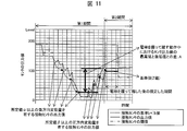
- FIG. 11 is a diagram for explaining the calibration of the reference level value of the present embodiment performed by the reference level value setting calibration unit 23 provided in the mobile terminal 1.
- the reference level value setting calibration unit 23 is configured such that the difference between the maximum value and the minimum value of the output value of the contact sensor during the operation in which the user grips and releases the electrode with a hand is equal to or greater than a predetermined value. Even if the output value of the contact sensor is larger than the reference value (Z value) for a certain period after the user holds and releases the electrode, the output value of the contact sensor is only in the first period.
- a reference level value of the contact sensor having a constant value in the second period, which is a part of the period, is set to (i) an output value output from the contact sensor at a timing when the second period starts, or (ii) the above Calibration is performed based on a plurality of output values of the contact sensor in a period prior to the second period. That is, when the output value of the contact sensor falls below the reference value (Z value) during a set period after the user holds and releases the electrode, the calibration of the reference level value of the contact sensor is Not done.
- the output value of the contact sensor falls below a reference value (Z value) for a certain period after the user grips and releases the electrode, the operation of the user holding and releasing the electrode is the user's mobile terminal Since there is a high possibility of an input operation to 1, the reference level value of the contact sensor is not calibrated.
- FIG. 12 is a flowchart for explaining the calibration of the reference level value of the present embodiment.
- steps (S41) to (S47) in FIG. 12 are the same as steps (S31) to (S37) in FIG. 10 of the above-described fourth embodiment, and thus description thereof is omitted here.
- step (S47) if the difference between the current maximum value and the minimum value Y1 is larger than the reference value B for calibrating the reference level value of the contact sensor, the output value of the contact sensor indicates that the user holds the electrode.
- step (S48) for determining whether or not the state larger than the reference value (Z value) has continued during the set period. If the state larger than the reference value (Z value) continues, The process proceeds to the step of calibrating the reference level value of the contact sensor (S49), and after calibrating the reference level value of the contact sensor, the process proceeds to the step of performing normal operation (S50). On the other hand, if the state larger than the reference value (Z value) is not continued for the set period in step (S48), the process returns to step (S42), and the minimum value and the maximum value are confirmed again.
- the flow shown in FIG. 12 is repeated for each first period, and until the end of each first period, the output value of the contact sensor does not fall below the threshold value of the contact sensor, or a value equal to or greater than a predetermined value ⁇ is present. If it is not detected or if the output value of the contact sensor falls below the reference value (Z value) for a certain period after the user grips and releases the electrode, calibrate the reference level value of the contact sensor. First, the flow is terminated.
- the contact sensor which can distinguish the input operation to a user's portable terminal 1 and the operation
- An information processing apparatus equipped with can be realized.
- the case where the output value of the contact sensor is larger than the reference value (Z value) for a certain period after the user grasps and releases the electrode is continued in the fourth embodiment described above.
- the present invention is not limited to this, and the above conditions may be added to any of the first to third embodiments.
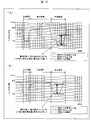
- FIG. 13 is a diagram for explaining the calibration of the reference level value of the present embodiment performed by the reference level value setting calibration unit 23 provided in the mobile terminal 1.
- FIG. 13A shows the case of the first contact sensor
- FIG. 13B shows the case of the second contact sensor.
- the output value of the first contact sensor may rise suddenly due to environmental changes. Accordingly, the reference level value of the first contact sensor is corrected to follow the output value of the first contact sensor, and the corrected reference level value of the first contact sensor may not be appropriate.
- FIG. 13B it is assumed that such a problem does not occur in the second contact sensor.
- the function of calibrating the reference level value of the contact sensor is made effective.
- the valid period in FIG. 13 is a period during which the function for calibrating the reference level value of the touch sensor is valid, and the invalid period is a period during which the function for calibrating the reference level value of the touch sensor is invalid. Therefore, when the user grasps both the electrode of the first contact sensor and the electrode of the second contact sensor, the function of calibrating the reference level value of the contact sensor becomes effective.
- Is configured to enable the function of calibrating the reference level value of the contact sensor when the state of gripping both the electrode of the first contact sensor and the electrode of the second contact sensor continues for a predetermined period or longer. This condition can be omitted. Further, when the user holds at least one of the first contact sensor electrode and the second contact sensor electrode for a predetermined period or longer, the reference level value of the contact sensor is set. The function of calibrating may be enabled.
- the reference level value setting calibration unit 23 determines that the difference A between the highest value and the lowest value of the output value of the contact sensor during the operation in which the user grasps and releases the electrode with his / her hand is the reference level value of the contact sensor. Is equal to or higher than the reference value B for calibrating the touch sensor, the reference level value of the touch sensor is either (i) the output value output from the touch sensor at the current timing, or (ii) the above-mentioned time period before the current timing. Calibration is performed based on a plurality of output values of the contact sensor.
- the contact sensor only for a sensor in which the difference A between the highest value and the lowest value of the contact sensor is equal to or greater than the reference value B for calibrating the reference level value of the contact sensor.
- the reference level value is calibrated.
- the reference level value of the contact sensor after the reference level value of the contact sensor is calibrated, it is determined whether the output values of the first contact sensor and the second contact sensor exceed the threshold values of the respective contact sensors. In this case, it is determined again whether to calibrate the reference level value of the contact sensor while the function of calibrating the reference level value of the contact sensor is enabled.
- the output value of the second contact sensor becomes the second contact. If the sensor threshold value is exceeded, the reference level value of the contact sensor may not be calibrated for the second contact sensor.
- the reference level value of the contact sensor may not be calibrated.
- FIG. 14 is a flowchart for explaining the calibration of the reference level value of the present embodiment.
- step (S51) it is determined whether the output values of the first contact sensor and the second contact sensor are below the threshold values of the respective contact sensors. When it is below, it progresses to step (S52) and it is judged whether the state where the output value of a 1st contact sensor and a 2nd contact sensor is less than the threshold value of each contact sensor is more than predetermined period. If it is longer than the predetermined period, the process proceeds to step (S53), and the minimum output value of the contact sensor during the operation in which the user's hand holds and releases the electrode in each of the first contact sensor and the second contact sensor. It is determined whether the difference A between the value and the maximum value of the output value of the contact sensor is greater than a reference value B for calibrating the reference level value of the contact sensor. Proceed to the step of calibrating the value (S54), and the reference level value of the contact sensor is calibrated.
- step (S55) after calibrating the reference level value of the contact sensor, it is determined whether the output values of the first contact sensor and the second contact sensor exceed the threshold values of the respective contact sensors. If not, it is determined again whether to calibrate the reference level value of the contact sensor while the function of calibrating the reference level value of the contact sensor is enabled.
- an information processing apparatus that can be used without causing the user to be aware of an abnormal state and that can sufficiently prevent malfunctions can be realized even in an information processing apparatus having a plurality of contact sensors.
- the sensor value when the object is not in contact may change due to a change in environment such as temperature. Therefore, the reference level for representing the sensor value in the non-contact state is periodically calibrated. The threshold for determining whether or not an object has touched is changed according to the increase or decrease of the reference level.
- the sensor value output from the contact sensor may change temporarily due to external factors (noise of radio waves such as wireless communication, impact caused by dropping, etc.).
- external factors noise of radio waves such as wireless communication, impact caused by dropping, etc.
- the sensor value will “decrease”, and if the capacitance decreases due to an increase in the impedance of the wiring section, etc.
- the value is “rising”.
- the reference level is calibrated when the sensor value is temporarily increased due to, for example, noise. In that case, the reference level is set to a value larger than the sensor value when there is no noise in the non-contact state.
- the threshold value for determining whether or not the object has touched according to the reference level is also corrected following the threshold level, so that it is set larger than the above threshold value when there is no noise. As a result, there arises a problem that it is erroneously determined whether or not an object is in contact.
- FIG. 17 is a block diagram illustrating an example of a main configuration of the mobile terminal 101.
- the mobile terminal 101 is an information processing apparatus including the contact sensor 11, a grip determination unit 112 (grip determination device), and a host control unit 13.
- the contact sensor 11 a grip determination unit 112 (grip determination device)
- a host control unit 13 a host control unit 13.
- the grip determination unit 112 includes a sensor control unit 121, a contact determination unit 122, a calibration unit 123, a rise determination unit 124, and a rise calibration unit 125 (calibration unit).
- the grip determination unit 112 includes a storage unit (not shown).
- the storage unit stores a reference level (reference value), a gripping threshold value, a release threshold value, and the like. Each unit of the grip determination unit 112 can read and write these stored values from the storage unit.
- the reference level is for representing a sensor value when the casing is not gripped by the user.
- the gripping threshold value is a threshold value for determining that the housing is gripped.
- the release threshold value is a threshold value for determining that the hand is released from the grip (the hand is released). For example, the gripping threshold is set to a value smaller than the reference level.
- the release threshold is set to a value smaller than the reference level and larger than the grip threshold.
- the difference between the reference level and the grip threshold and the difference between the reference level and the release threshold are set in advance. That is, when the reference level is determined, the gripping threshold value and the release threshold value are automatically determined accordingly.
- the reference level is a variable that is set to be changeable in order to provide a reference (gripping threshold value, release threshold value) for determining whether or not there is gripping.
- the gripping threshold value and the release threshold value are different in order to determine the presence / absence of gripping as hysteresis, but they may be the same value.
- the reference level, the grip threshold, and the release threshold are set for each contact sensor 11.
- the sensor control unit 121 operates the contact sensor 11 at a predetermined timing, and acquires a sensor value as an output of the contact sensor 11.
- the sensor control unit 121 acquires a sensor value from the contact sensor 11 at regular intervals.
- the sensor control unit 121 acquires sensor values from the respective contact sensors 11 at regular intervals.
- the sensor control unit 121 outputs the sensor value to the contact determination unit 122.
- the contact determination unit 122 compares the sensor value with the gripping threshold value, and determines that the user's hand is in contact with the contact sensor 11 (via the housing) when the sensor value becomes smaller than the gripping threshold value. Moreover, the contact determination part 122 memorize
- the contact determination unit 122 determines that the user's hand is holding the housing (the portable terminal 101) when the plurality of (both sides) contact sensors 11 are in a contact state. For example, when only the contact sensor 11 on one side is in a contact state and the contact sensor 11 on the other side is in a non-contact state, the contact determination unit 122 determines that the user's hand is not holding the casing. Also good. When there is only one contact sensor 11 provided in the mobile terminal 101, the contact determination unit 122 determines the presence or absence of gripping based on the contact state of the contact sensor 11. The contact determination unit 122 outputs determination result information regarding the presence / absence of gripping to the host control unit 13. In the following description, for the sake of simplicity, determination of the contact state of one contact sensor 11 will be described.
- the calibration unit 123 acquires the sensor value from the sensor control unit 121 at a predetermined timing, and calibrates the reference level based on the sensor value. For example, the calibration unit 123 calibrates the reference level at regular intervals. The calibration unit 123 also calibrates the reference level when the mobile terminal 101 is turned on and when the grip determination function is turned on. The calibration unit 123 acquires sensor values a plurality of times, and sets an average value (or intermediate value) of the plurality of sensor values as a reference level. When the reference level is changed, the gripping threshold value and the release threshold value are also changed based on the information for changing the reference level. Thereby, the reference level for expressing the sensor value at the time of non-contact can be calibrated according to environmental changes, such as temperature.
- the rise determination unit 124 acquires a sensor value from the sensor control unit 121.
- the rise determination unit 124 includes a first rise determination unit 124a (first determination unit) and a second rise determination unit 124b (second determination unit).
- the first rise determination unit 124a determines whether or not the sensor value is rising at a slope equal to or greater than a predetermined slope in the first period Pa having a predetermined length.
- the first increase determination unit 124a includes (A) sensor value increase amount in the first period Pa> positive first threshold value, (B) sensor value at the end of the first period Pa> reference level at the start of the first period Pa; When satisfy
- the increase amount of the sensor value is obtained by subtracting the sensor value at the start of the first period Pa from the sensor value at the end of the first period Pa.
- the “sensor value increase amount” is a negative value. Since the first threshold value is a predetermined positive value, the determination formula A is used to determine whether or not the sensor value is rising with a gradient equal to or greater than a predetermined gradient.
- the second rise determination unit 124b determines whether or not the sensor value is rising at a slope equal to or greater than a predetermined slope in the second period Pb having a predetermined length. Specifically, the second rise determination unit 124b (C) sensor value increase amount in second period Pb> positive second threshold value, (D) sensor value at the end of the second period Pb> reference level at the start of the second period Pb; When satisfying, it determines with satisfy
- the end of the second period Pb is after the end of the first period Pa.
- the second rise determination unit 124b determines whether or not the sensor value is rising at a slope greater than or equal to a predetermined slope at a timing after the first rise determination section 124a.
- the length of the first period Pa and the length of the second period Pb, and the first threshold value and the second threshold value may be the same or different.
- the first threshold value and the second threshold value are large values such that the determination formulas A and C are not satisfied when the sensor value increases with temperature.
- the rise determination unit 124 outputs the determination result of the first rise determination unit 124a and the determination result of the second rise determination unit 124b to the rise calibration unit 125.
- the rising calibration unit 125 calibrates the reference level to increase when the sensor value tends to increase. Specifically, when both the first condition and the second condition are satisfied, the rising calibration unit 125 corrects the reference level in the positive direction after the end of the second period Pb, that is, increases the reference level. . For example, the rising calibration unit 125 changes the reference level to the sensor value at the end of the second period Pb. On the other hand, when any one of the first condition and the second condition is not satisfied, the ascending calibration unit 125 does not increase the reference level.
- the above judgment formulas A and C are not satisfied by the normal temperature change.
- calibration increase / decrease
- the reference level is a sensor in a non-contact state. It will be set to the lower side than the value. The same can occur when calibration is performed by the calibration unit 123 when the portable terminal 101 is placed on a metal desk (having a large capacitance).
- the sensor value increases greatly from the reference level set low.
- the increase of the sensor value when the hand is released satisfies the determination formulas A and C.
- the rise determination unit 124 detects, for example, such an increase in sensor value when the hand is released, and the rise calibration unit 125 raises the reference level set low to an appropriate value.
- the ascending calibration unit 125 corrects the reference level in the positive direction according to the increase in sensor value. Since the sensor value can be lowered due to a user's grip or the like, when the sensor value is lowered, the ascending calibration unit 125 does not change the reference level. If the reference level is lowered in accordance with the drop in the sensor value, the gripping threshold is also lowered, and the user's grip cannot be detected.
- FIG. 18 is a diagram illustrating a reference level calibration process in the reference example when affected by periodic electromagnetic wave noise.
- the increase determination unit performs only the determination of the first condition, for example, and the increase calibration unit performs the increase correction of the reference level based only on the determination result of the first condition. That is, in the reference example, the reference level is calibrated so as to increase the reference level when the sensor value increases with a gradient equal to or greater than a predetermined value in one period.
- the horizontal axis represents time, and the vertical axis represents values such as sensor values. In the following drawings, the reference level and the sensor value are appropriately shifted for easy viewing.
- the sensor value may temporarily increase due to the influence.
- the period during which the sensor value increases due to such noise is typically 1 second or less, for example, about 400 milliseconds.
- this sensor value increase is detected and the reference level is increased to the peak of the sensor value.
- the grip threshold Th1 and the release threshold Hys1 also increase by the same amount.
- the sensor value drops to the original value, but the reference level is maintained at the height of the peak. For this reason, the sensor value becomes smaller than the grip threshold Th1, and it is erroneously determined that the contact sensor is in a contact state. Until the sensor value rises again due to noise and the sensor value becomes larger than the release threshold value Hys1, the contact state is erroneously determined. While noise is occurring, the contact state is erroneously detected in accordance with the noise cycle.
- the reference level is corrected to be increased based on the increase in the sensor value for only one period, the reference level is corrected to increase when the sensor value is temporarily increased due to noise or impact of dropping, and this problem occurs.
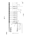
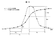
- FIG. 19 is a timing chart showing determination processing of the ascent determination unit 124 of the present embodiment.
- the horizontal axis represents time, and the vertical axis represents sensor values.
- a solid curve represents a variation example of the sensor value when the hand is released from the contact sensor 11.
- the dashed curve represents an example of sensor value variation due to noise.
- Black dots in the figure indicate sensor values that the sensor control unit 121 acquires at regular intervals. For example, the sensor control unit 121 acquires (senses) the sensor value at a period of about 60 milliseconds.
- the predetermined first period Pa is for three sensing periods, and the predetermined first period Pb is for four sensing periods. Further, the delay period Dx from the start of the first period Pa to the start of the second period Pb is set to five sensing cycles. These periods can be set arbitrarily.
- the time when the first rise determination unit 124a starts determining the first condition (at the start of the first period Pa) is defined as t1 (first time).
- the time after the first period Pa from the determination start (at the end of the first period Pa) is defined as t2 (second time).
- the first increase determination unit 124a acquires the sensor value and the reference level at time t1, and acquires the sensor value at time t2.
- the time after the delay period Dx from the time t1 (at the start of the second period Pb) is defined as t3 (third time).
- the time after the second period Pb from the time t3 (at the end of the second period Pb) is defined as t4 (fourth time).
- the time t3 is after the time t1, but may be the same as the time t1 or may be before the time t1.
- time t4 is after time t2.
- the second increase determination unit 124b acquires the sensor value and the reference level at time t3, and acquires the sensor value at time t4.
- the second increase determination unit 124b determines that the second condition is satisfied if (C) the increase amount Rb is greater than the positive second threshold value and (D) the sensor value at time t4 is greater than the reference level at time t3. To do. If the amount of increase in the solid curve shown is Rb1, the amount of increase Rb1 is larger than the positive second threshold value. The solid curve shown satisfies the second condition.
- the dashed curve representing fluctuation due to noise does not satisfy the second condition even if the first condition is satisfied.
- the increase amount is Rb2
- the increase amount Rb2 becomes a negative value.
- FIG. 20 is a timing chart showing the reference level calibration process of the ascending calibration unit 125.
- the horizontal axis represents time, and the vertical axis represents sensor values.
- a solid curve represents a variation example of the sensor value when the hand is released from the contact sensor 11.
- the reference level is indicated by a thin line. Since the fluctuation of the sensor value satisfies both the first condition in the first period Pa and the second condition in the second period Pb, the rising calibration unit 125 sets the reference level to the sensor value at time t4 after time t4. Raise (correct in the positive direction).
- the reference level may be corrected to the immediately preceding sensor value as described above, or may be corrected to a representative value (such as an average value) obtained by using several sensor values.
- the reference level may be corrected in the positive direction so as to be larger than the reference level at time t1. Regardless of whether or not the first condition is satisfied, the correction (increase correction) in the positive direction of the reference level is not performed until time t4 when the determination of the second condition is performed.
- the first period Pa, the positive first threshold value, the second period Pb, the positive second threshold value, and the delay period Dx are sensor value fluctuations (rising slope, fluctuation amount, fluctuation) that are not to be corrected for the reference level. It is preferable to set according to the period.
- the length from time t1 to time t4 is typically 1 second or less, for example, so that the reference level can be increased and corrected according to the fluctuation of the sensor value when the hand is released, ignoring the fluctuation of the sensor value due to noise. Can be set to 600 milliseconds or less.
- the lengths of the first period Pa, the second period Pb, and the delay period Dx can be set so that the interval from time t2 to time t4 is equal to or greater than the interval from time t1 to time t2.
- the first period Pa it is possible to quickly detect the increasing tendency of the sensor value, so that the setting of the second period Pb can be made close to the sensor value fluctuation period that is not a target. For this reason, the period of one ascent correction (from time t1 to time t4) is shortened, and it becomes possible to detect the sensor value fluctuation of the calibration target in a shorter cycle.
- the first increase determination unit 124a sets the first period again after time t4 (for example, from the next sensing at time t4). Set and start determining the first condition. As described above, by repeatedly determining the first period Pa and the second period Pb, the reference level can be corrected to be increased without overlooking the increase in the sensor value when the hand is released from the contact sensor 11. If the first condition is not satisfied, the second condition is not subsequently determined, the first period is set again before time t4, and the first rise determination unit 124a starts determining the first condition. May be. By doing so, it is possible to omit the useless determination of the second condition and promptly follow the reference level with the increase in the sensor value.
- FIG. 21 is a diagram showing a reference level calibration process in the present embodiment when affected by periodic electromagnetic noise.
- the horizontal and vertical axes are the same as in FIG.
- the temporary increase in sensor value for a short period does not satisfy either the first condition or the second condition, so the reference level is maintained at the original value. For example, if the determination of the first condition is started (time t1) while the sensor value is increasing due to the influence of noise, the first condition is not satisfied.
- the grip determination unit 112 can correctly detect the grip / release timing of the user.
- a sensor value that is short-term and temporary due to noise of electromagnetic waves or a shock of dropping is determined by determining an upward tendency of the sensor value in two stages (first increase determination unit 124a and second increase determination unit 124b). It is possible to avoid an unnecessary reference level calibration that causes an erroneous determination due to an increase in.
- Emodiment 8 In the present embodiment, a configuration will be described in which the reference level is once corrected to be increased when the first condition is satisfied.
- the configuration of the portable terminal 101 is the same as that shown in FIG.
- the determination process of the rise determination unit 124 is the same as that in the above-described embodiment. 22 to 26, the horizontal axis represents time, and the vertical axis represents sensor value.
- FIG. 22 is a timing chart showing the reference level calibration process of the ascending calibration unit 125 in this embodiment.
- a solid curve represents a variation example of the sensor value when the hand is released from the contact sensor 11. This change in sensor value satisfies both the first condition in the first period Pa and the second condition in the second period Pb.
- the rising calibration unit 125 increases the reference level to the sensor value at time t2.
- the second increase determination unit 124b determines the second condition in the second period Pb.
- the rising calibration unit 125 further increases the reference level to the sensor value at time t4.
- the reference level is once corrected to be increased.
- FIG. 23 is a timing chart showing the reference level calibration process of the ascending calibration unit 125 in the present embodiment.
- the dashed curve represents an example of sensor value variation due to noise. This change in sensor value satisfies the first condition in the first period Pa, but does not satisfy the second condition in the second period Pb.
- the rising calibration unit 125 increases the reference level to the sensor value at time t2.
- the ascending calibration unit 125 stores the reference level before the change (time t1). Thereafter, when it is determined that the second condition is not satisfied (after time t4), the ascending calibration unit 125 returns the reference level to the reference level at time t1. That is, the change of the reference level once raised is canceled.
- the reference level set low (calibrated) can be appropriately corrected for increase.
- FIG. 24 is a timing chart showing an example of the reference level calibration process in the seventh embodiment.
- the fluctuation of the sensor value indicated by the dotted line satisfies both the first condition and the second condition.
- the reference level increase correction indicated by the solid line is not performed until it is determined that the second condition is also satisfied. Only at time t4 when it is determined that the second condition is satisfied, the reference level is corrected to increase to the sensor value at time t4.
- the sensor value in the non-contact state increases between time t1 and time t4 due to reasons such as the mobile terminal 101 being separated from the metal body.
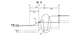
- FIG. 25 is a timing chart illustrating an example of a reference level calibration process according to the eighth embodiment.
- the fluctuation of the sensor value indicated by the dotted line is the same as that in FIG. If it is determined that the first condition is satisfied at time t2, the reference level indicated by the solid line is corrected to be increased to the sensor value at time t2. As the reference level increases, the gripping threshold Th1 and the release threshold Hys1 also increase. Thereafter, when it is determined that the second condition is satisfied at time t4, the reference level is corrected to be increased to the sensor value at time t4.
- the grip determination unit 112 can correctly detect the user's grip performed before the determination of the second condition.
- the reference level can be quickly followed by the fluctuation of the sensor value in the non-contact state, and the user operability can be improved.
- FIG. 26 is a timing chart illustrating an example of a reference level calibration process according to the eighth embodiment.
- the fluctuation of the sensor value indicated by the dotted line satisfies the first condition but does not satisfy the second condition.
- the reference level and the gripping threshold Th1 are not increased at the time t2. Therefore, even if the fluctuation of the sensor value that satisfies the first condition is due to noise or the like, a small fluctuation (down) of the sensor value after the noise is not erroneously determined as gripping.
- a sensor that detects the value of a physical quantity that changes with the contact of an object as disclosed in Patent Document 1 is a value of a physical quantity when the object is not in contact with a change in the surrounding environment. May change. For example, in the case of a capacitance sensor, a value detected when an object is not in contact changes due to a temperature change around the sensor. If the threshold for determining whether or not an object has touched at this time is unchanged, a sensor malfunction (such as determining that the user is touching the touch sensor but not touching it) may occur.
- FIG. 15 is a graph showing conventional calibration of the reference level.
- the reference level is calibrated according to the value (detected value) of the physical quantity acquired at regular intervals, and the threshold value is changed according to the calibrated reference level.
- the conventional technology has a problem that malfunction of the contact sensor cannot be sufficiently prevented.
- the reference level is extremely increased by calibration in a state where no object is in contact with the contact sensor, there is a possibility that the detection of the presence / absence of gripping of the mobile terminal may not operate normally.
- the threshold value when the threshold value is made to follow the reference level, the threshold value is significantly increased when the reference level is extremely increased. During this time, when an object (such as a desk) having a dielectric constant lower than that of the hand contacts the contact sensor, it may be erroneously detected as a grip.
- FIG. 27 is a block diagram illustrating an example of a main configuration of the mobile terminal 201.
- the mobile terminal 201 includes the contact sensor 11, the grip determination unit 212, and the host control unit 13. Note that in FIG. 27, some arrows are omitted in consideration of the visibility of the drawing.
- the grip determination unit 212 includes a sensor control unit 221, a contact determination unit 222, a calibration unit (reference value changing unit) 223, and an abnormality detection mode determination unit 224.
- the grip determination unit 212 includes a storage unit (not shown).
- the storage unit includes a reference level (reference value), a gripping threshold value (first threshold value), a release threshold value (fourth threshold value), an abnormality detection mode start threshold value (second threshold value), an abnormality detection mode end threshold value (third threshold value), and the like.
- Each unit of the grip determination unit 212 can read and write these stored values from the storage unit.
- the reference level is for representing a sensor value when the casing is not gripped by the user.
- the gripping threshold value is a threshold value for detecting that the housing is gripped.
- the release threshold value is a threshold value for detecting that the casing is not gripped.
- the release threshold value is a threshold value for detecting that the casing is released (the hand is released).
- the gripping threshold is set to a value smaller than the reference level.
- the release threshold is set to a value smaller than the reference level and larger than the grip threshold.
- the difference between the reference level and the grasping threshold and the difference between the reference level and the release threshold are set in advance. That is, when the reference level is determined, the gripping threshold value and the release threshold value are automatically determined accordingly.
- the reference level is a variable that can be changed in order to provide a reference (a gripping threshold value and a release threshold value) for determining the presence or absence of gripping.
- the gripping threshold value and the release threshold value are different from each other, but they may be the same value.
- the abnormality detection mode start threshold is a threshold for determining the start of the abnormality detection mode.
- the abnormality detection mode end threshold is a threshold for determining the end of the abnormality detection mode.
- the abnormality detection mode start threshold and the abnormality detection mode end threshold can be set for each contact sensor 11.
- the abnormality detection mode start threshold is set to a value that is smaller than the reference level and different from the gripping threshold.
- the abnormality detection mode end threshold is set to a value smaller than the reference level and larger than the abnormality detection mode start threshold. Details of the abnormality detection mode will be described later.
- the difference between the reference level and the abnormality detection mode start threshold and the difference between the reference level and the abnormality detection mode end threshold are set in advance. That is, when the reference level is determined, the abnormality detection mode start threshold and the abnormality detection mode end threshold are automatically determined accordingly. This is the same as the grip threshold and the release threshold.
- the abnormality detection mode start threshold and the abnormality detection mode end threshold are different from each other, but these may be the same value.
- the sensor control unit 221 operates the contact sensor 11 at a predetermined timing, and acquires a sensor value as an output of the contact sensor 11.
- the sensor control unit 221 acquires a sensor value from the contact sensor 11 at regular intervals.
- the sensor control unit 221 acquires sensor values from the respective contact sensors 11 at regular intervals.
- the sensor control unit 221 outputs the sensor value to the contact determination unit 222 and the abnormality detection mode determination unit 224.
- the contact determination unit 222 compares the sensor value with the gripping threshold value, and determines that the user's hand is in contact with the contact sensor 11 (via the housing) when the sensor value becomes smaller than the gripping threshold value. Moreover, the contact determination part 222 memorize
- the contact determination unit 222 determines that the user's hand is holding the mobile terminal 201 when a plurality of (both sides) contact sensors 11 are in a contact state. For example, when only the contact sensor 11 on one side is in a contact state and the contact sensor 11 on the other side is in a non-contact state, the contact determination unit 222 determines that the user's hand is not holding the mobile terminal 201. May be. When there is only one contact sensor 11 provided in the mobile terminal 201, the contact determination unit 222 determines whether or not there is a grip based on the contact state of the contact sensor 11. The contact determination unit 222 outputs determination result information regarding the presence / absence of gripping to the host control unit 13.
- the calibration unit 223 acquires the sensor value from the sensor control unit 221 at a predetermined timing, and calibrates the reference level based on the sensor value (changes the reference value). For example, the calibration unit 223 calibrates the reference level at regular intervals. The calibration unit 223 also calibrates the reference level when the mobile terminal 201 is turned on and when the grip determination function is turned on. For example, the calibration unit 223 acquires sensor values a plurality of times, and sets an average value (or intermediate value) of the plurality of sensor values as a reference level. When the reference level is changed, the gripping threshold value, the release threshold value, the abnormality detection mode start threshold value, and the abnormality detection mode end threshold value are also changed based on the information that has changed the reference level. Thereby, the reference level for expressing the sensor value at the time of non-contact can be calibrated according to environmental changes, such as temperature.
- the abnormality detection mode determination unit 224 includes an abnormality detection mode start determination unit (first determination unit) 224a and an abnormality detection mode end determination unit (second determination unit) 224b.
- the abnormality detection mode start determination unit 224a determines that the abnormality detection mode is started when the sensor value is equal to or less than the abnormality detection mode start threshold.
- the abnormality detection mode end determination unit 224b determines that the abnormality detection mode is ended when the sensor value is equal to or greater than the abnormality detection mode end threshold. Then, when the abnormality detection mode end determination unit 224b determines that the abnormality detection mode has ended, the abnormality detection mode determination unit 224 sends the information to the calibration unit 223.
- the calibration unit 223 acquires a sensor value from the sensor control unit 221 and calibrates the reference level based on the sensor value.
- the abnormality detection mode start determination unit 224a may determine that the sensor value is equal to or less than the abnormality detection mode start threshold for the arbitrary at least one contact sensor 11 as the start of the abnormality detection mode.
- the abnormality detection mode end determination unit 224b may determine, for example, that the abnormality detection mode ends with respect to any at least one contact sensor 11 that the sensor value is equal to or greater than the abnormality detection mode end threshold.
- the portable terminal 201 provided with the contact sensor 11 detects the presence or absence of gripping using the contact sensor 11, and has a reference level calibration function shown in (A) and (B) below.
- the reference level is updated to the sensor value at the time of calibration.
- the threshold for detecting the presence / absence of gripping is made to follow the reference level, so that even if the reference level fluctuates due to calibration, the user's operation feeling is not impaired. It becomes possible to detect the presence or absence.
- the reference level becomes extremely high by calibration. There is a concern that it rises (when the direction that changes as the sensor value is gripped is defined as the negative direction).
- each contact sensor 11 The electrical path (electrode main body or wiring) of each contact sensor 11 depending on the state in which the mobile terminal 201 has a plurality of contact sensors 11 and foreign matter such as water is in contact with the mobile terminal 201, for example. Is in direct contact with water.
- the electrical paths of the contact sensors 11 are coupled to each other through water, and the state of an electrical path of a certain contact sensor 11 (for example, a state in which a DC voltage of 3 V is applied) is changed to another contact sensor 11. The reason is that it affects the state of the electrical path.
- FIG. 28 is a timing chart for explaining an example mechanism of occurrence of erroneous detection.
- the vertical axis indicates the sensor value sv that is the output of a certain contact sensor 11 and the magnitude of the reference level rv that is calibrated by the sensor value sv.
- the vertical axis also shows the magnitudes of the gripping threshold value TH1 and the release threshold value Hys1 corresponding to the reference level rv.
- the horizontal axis indicates the passage of time.
- the contact sensor 11 is in a general non-contact state s1.
- the state s1 there is no contact of the object with the contact sensor 11, and there is no other factor that fluctuates the sensor value sv. Therefore, the sensor value sv and the reference level rv are constant values.
- the state shifts to a state s12 where the reference level rv is extremely increased until time t2.
- the sensor value sv rises extremely (see symbol sv12 in FIG. 28).
- the reference level rv also rises extremely (see symbol rv12 in FIG. 28).
- the grasping threshold value TH1 and the release threshold value Hys1 are also extremely increased following the reference level rv (see symbols TH112 and Hys112 in FIG. 28, respectively).
- the state shifts to the non-contact state s23 of the contact sensor 11 until time t3.
- the sensor value sv returns to the same level as the state s1.
- the reference level rv is not calibrated in accordance with the sensor value sv at this time, the reference level rv does not return to the same level as the state s1, but the level after the calibration related to the state s12 (that is, extremely increased) Is maintained).
- the touch sensor 11 shifts to the light contact state s34 until time t4.
- the light contact state s34 is a state in which an object is lightly in contact with the contact sensor 11.
- the hand instantaneously contacts the contact sensor 11, and an object such as a desk is in contact with the contact sensor 11.
- the light contact state s34 is not a state where there is a grip, it should be determined as a non-contact state of the contact sensor 11.
- the sensor value sv decreases in the light contact state s34, but the minimum value sv34 of the sensor value sv in the light contact state s34 is larger than the grip threshold TH1 in the state s1.
- the reference level rv, the grasping threshold value TH1, and the release threshold value Hys1 are maintained to be large values after the reference level rv calibration related to the state s12.
- a phenomenon occurs in which the minimum value sv34 falls below the grip threshold TH1. This phenomenon is synonymous with the occurrence of a false detection in which it is determined that the contact state of the contact sensor 11 (and thus there is grip) in spite of the light contact state s34.
- the state shifts to the state s4.
- the sensor value sv increases and the sensor value sv returns to the same level as the state s1.
- the calibration cal is a general calibration function represented by the above (A) and (B).
- FIG. 29 is a timing chart illustrating the abnormality detection mode.
- the vertical axis represents the magnitudes of the sensor value sv, the reference level rv, the grip threshold TH1, and the release threshold Hys1.
- the horizontal axis indicates the passage of time.
- the behavior sva of the sensor value sv corresponds to the case where there is no contact of the object with the contact sensor 11 and the reference level rv according to the cases (C) and (D) described above does not increase excessively.
- the behavior of the sensor value sv is shown.
- the behavior svb of the sensor value sv indicates the behavior of the sensor value sv when an extreme increase in the sensor value sv occurs.
- the behavior svc of the sensor value sv indicates the behavior of the sensor value sv when the portable terminal 201 is gripped and then released.
- the behavior svd of the sensor value sv indicates the behavior of the sensor value sv when the object is in light contact with the contact sensor 11 (that is, in the light contact state) and then the object leaves the contact sensor 11. Further, the portion of the sensor value sv corresponding to the period in which the presence of gripping is detected is indicated by a solid line, and the portion of the sensor value sv corresponding to the period in which it is detected that there is no gripping is indicated by a broken line.
- the reference level rv is calibrated when it is detected that there is gripping with respect to the behavior svd of the sensor value sv in the state shown in (b) of FIG. Since the sensor value sv exhibits the behavior sva at the time of calibration, the extreme rise of the reference level rv is canceled by the calibration. Needless to say, when the extreme rise of the reference level rv is canceled, the extreme rises of the grip threshold TH1 and the release threshold Hys1 are canceled following the reference level rv.
- a light contact state in which an object is lightly touching the contact sensor 11 is positively detected in order to calibrate the reference level rv when it is detected that there is gripping with respect to the behavior svd of the sensor value sv.
- a mode is defined, and this mode is referred to as an “abnormality detection mode”.
- FIG. 30 is a timing chart illustrating a first example of the abnormality detection mode determination unit 224 and the calibration unit 223. With respect to the timing chart shown in FIG. 30, differences from the timing chart shown in FIG. 28 will be mainly described.
- the vertical axis corresponds to the reference level rv in addition to the sensor value sv, the reference level rv, the gripping threshold value TH1, and the release threshold value Hys1, which are defined similarly to the timing chart shown in FIG.
- the magnitudes of the abnormality detection mode start threshold TH6 and the abnormality detection mode end threshold Hys6 to be performed are shown.
- the horizontal axis indicates the passage of time.
- the abnormality detection mode start threshold TH6 and the abnormality detection mode end threshold Hys6 follow the reference level rv in the same manner as the gripping threshold TH1 and the like.
- the abnormality detection mode start threshold TH6 is set to a value smaller than the reference level rv and larger than the grip threshold TH1.
- the abnormality detection mode end threshold Hys6 is set to a value smaller than the reference level rv and larger than the abnormality detection mode start threshold TH6. Furthermore, the abnormality detection mode end threshold value Hys6 is set to a value that is greater than or equal to the release threshold value Hys1 (here, greater than the release threshold value Hys1).
- the touch sensor 11 shifts to the light contact state s34 ′ until time t4. It is assumed that the behavior of the sensor value sv in the light contact state s34 ′ is the same as the behavior of the sensor value sv in the light contact state s34.
- the sensor value sv decreases.
- the abnormality detection mode start determination unit 224a (see FIG. 27) of the mobile terminal 201 detects this and determines that the abnormality detection mode is started. After the abnormality detection mode starts, the abnormality detection mode continues.
- the sensor value sv increases.
- the abnormality detection mode end determination unit 224b detects this and determines that the abnormality detection mode ends.
- the abnormality detection mode continues from the timing tc when the sensor value sv becomes equal to or lower than the abnormality detection mode start threshold TH6 to the timing td when the sensor value sv becomes equal to or higher than the abnormality detection mode end threshold Hys6.
- the abnormality detection mode end determination unit 224b determines that the abnormality detection mode has ended, the continued abnormality detection mode ends, but the abnormality detection mode determination unit 224 sends the information to the calibration unit 223. .
- the calibration unit 223 acquires the sensor value sv from the sensor control unit 221 (see FIG. 27) of the mobile terminal 201, and the reference level rv based on the acquired sensor value sv. Calibrate
- the calibration cal2 is a general calibration function represented by (A) and (B) described above, and is performed at the same timing as the calibration cal according to FIG.
- the calibration cal1 is a calibration performed by the calibration unit 223 based on information from the abnormality detection mode determination unit 224 (information indicating that it is determined that the abnormality detection mode has ended), and is performed prior to the calibration cal2.
- the reference level rv can be quickly calibrated when it is detected that a grip is present when an object is lightly touching the contact sensor 11.
- the abnormality detection mode end determination unit 224b detects whether or not the sensor value sv is equal to or greater than the abnormality detection mode end threshold Hys6 by using a value equal to or greater than the release threshold Hys1 as the abnormality detection mode end threshold Hys6. It is preferable to do this. Thereby, calibration can be performed after the contact sensor 11 shifts to the non-contact state.
- FIG. 31 is a timing chart illustrating a second example of the abnormality detection mode determination unit 224 and the calibration unit 223. With regard to the timing chart shown in FIG. 31, differences from the timing chart shown in FIG. 30 will be mainly described.
- the abnormality detection mode start determination unit 224a does not start the abnormality detection mode until it is further detected that the state where the sensor value sv is equal to or less than the abnormality detection mode start threshold TH6 continues for a predetermined time pt. judge.
- the behavior of the sensor value sv in the non-contact state s23 ′ is the same as the behavior of the sensor value sv in the non-contact state s23, except for the noise component svn1 generated in the sensor value sv.
- the noise component svn1 indicates a rapid fluctuation of the sensor value sv so that the sensor value sv instantaneously becomes equal to or less than the abnormality detection mode start threshold TH6.
- the abnormality detection mode start determination unit 224a determines whether or not the period tef from the timing te to the timing tf is equal to or longer than the predetermined time pt.
- the timing te is a timing at which the sensor value sv becomes equal to or less than the abnormality detection mode start threshold TH6 in the noise component svn1.
- Timing tf is timing when the sensor value sv again exceeds the abnormality detection mode start threshold TH6 in the noise component svn1.
- the abnormality detection mode start determination unit 224a does not determine that the abnormality detection mode is started.
- the abnormality detection mode start determination unit 224a determines that the abnormality detection mode is started after a predetermined time pt has elapsed from the timing tc.
- the grip determination unit 212 may be provided with a mode determination counter (not shown).
- the mode determination counter the mobile terminal 201 may be provided with a timer-dedicated device, or a timer function in a sensor microcomputer provided in the mobile terminal 201 may be used.
- An example of the predetermined time pt is 600 ms, but is not limited thereto.
- FIG. 32 is a timing chart for explaining a third example of the abnormality detection mode determination unit 224 and the calibration unit 223. With respect to the timing chart shown in FIG. 32, differences from the timing chart shown in FIG. 30 will be mainly described.
- the abnormality detection mode end determination unit 224b detects that the abnormality detection mode is ended only when it is further detected that the state in which the sensor value sv is equal to or higher than the abnormality detection mode end threshold Hys6 continues for a predetermined time pt. judge.
- the behavior of the sensor value sv in the light contact state s34 ′′ is the same as the behavior of the sensor value sv in the light contact state s34 except for the noise component svn2 generated in the sensor value sv.
- the noise component svn2 indicates a rapid fluctuation of the sensor value sv so that the sensor value sv instantaneously becomes equal to or higher than the abnormality detection mode end threshold value Hys6.
- the abnormality detection mode end determination unit 224b determines whether or not the period tgh from the timing tg to the timing th is equal to or longer than the predetermined time pt.
- the timing tg is a timing at which the sensor value sv becomes equal to or higher than the abnormality detection mode end threshold Hys6 in the noise component svn2.
- the timing th is a timing at which the sensor value sv becomes less than the abnormality detection mode end threshold Hys6 again in the noise component svn2.
- the abnormality detection mode end determination unit 224b since the period tgh is not equal to or longer than the predetermined time pt, the abnormality detection mode end determination unit 224b does not determine that the abnormality detection mode has ended.
- the abnormality detection mode end determination unit 224b determines that the abnormality detection mode is ended after a predetermined time pt has elapsed from the timing td.
- the reference level rv is calibrated when it is detected that there is gripping with respect to the behavior svd of the sensor value sv in the state shown in FIG.
- both the abnormality detection mode start threshold value TH6 and the abnormality detection mode end threshold value Hys6 are smaller than both the gripping threshold value TH1 and the release threshold value Hys1.
- the abnormality detection mode start threshold value TH6 and the abnormality detection mode end threshold value Hys6 are small, so that the start of the abnormality detection mode is not determined by the behavior svc unless the reference level rv increases (FIG. 33). (See medium code br).
- the abnormality detection mode start determination unit 224a uses the behavior svc to detect the abnormality detection mode. Not determined to be the start of
- the abnormal detection mode is set to a state in which it is erroneously detected that there is a grip. (It is erroneously detected that there is a grip when there is no object contact with the contact sensor. Different from the state). In this mode, even if it is determined that there is a grip once due to false detection (lightly touching, placing it on a metal desk, etc.), information that the user releases contact with the contact sensor or does not touch the contact sensor
- the reference level can be quickly calibrated by lifting the processor.
- the direction in which the sensor value changes as the grip portion (housing) is gripped is defined as a negative direction. Therefore, the terms “exceed” and “below” Means “greater than” and “smaller value”. However, when the mobile terminal 201 is designed with the polarity of the contact sensor 11 reversed, the direction in which the sensor value changes as the casing is gripped is the positive direction. In this case, the terms “over” and “below” may be understood to mean the states “smaller value” and “larger value”, respectively.
- Control blocks of portable terminals 1, 101, and 201 may be realized by a logic circuit (hardware) formed in an integrated circuit (IC chip) or the like. It may be realized by software using a Central Processing Unit.
- the mobile terminals 1, 101, and 201 include a CPU that executes instructions of a program, which is software that implements each function, and a ROM (Read CPU) in which the program and various data are recorded so as to be readable by the computer (or CPU). Only Memory) or a storage device (these are referred to as “recording media”), RAM (Random Access Memory) for expanding the program, and the like. And the objective of this invention is achieved when a computer (or CPU) reads the said program from the said recording medium and runs it.
- a “non-temporary tangible medium” such as a tape, a disk, a card, a semiconductor memory, a programmable logic circuit, or the like can be used.
- the program may be supplied to the computer via an arbitrary transmission medium (such as a communication network or a broadcast wave) that can transmit the program.
- a transmission medium such as a communication network or a broadcast wave
- the present invention can also be realized in the form of a data signal embedded in a carrier wave in which the program is embodied by electronic transmission.
- the information processing apparatus includes a reference level value setting calibration unit having a function of calibrating the reference level value of the contact sensor by performing an operation in which the user grasps and releases the electrode with a hand.
- the reference level value setting calibration unit sets a reference level value of the contact sensor having a constant value based on an output value output from the contact sensor or a plurality of output values output from the contact sensor. And enabling the function of calibrating the reference level value of the contact sensor when the output value output from the contact sensor becomes a value determined that the user's hand has touched the electrode.
- the output is output from the contact sensor.
- the reference level value of the contact sensor is calibrated based on the output value or a plurality of output values output from the contact sensor, and the contact sensor is set based on the reference level value of the calibrated contact sensor. Whether or not the user's hand touches the electrode is determined based on a threshold value.
- the output value of the contact sensor at the timing when the user grasps and releases the electrode with a hand is separated from the electrode. If the value is equal to or greater than the value determined to be met, it is preferable not to calibrate the reference level value of the contact sensor.
- the setting calibration unit for the reference level value of the information processing apparatus starts from the timing when the output value output from the contact sensor becomes a value determined that the user's hand has touched the electrode. Either after a predetermined period and after calibrating the reference level value of the contact sensor, or when the output value of the contact sensor is greater than or equal to a value determined that the user's hand has moved away from the electrode. It is preferable to disable the function of calibrating the reference level value.
- the information per predetermined time when determining the maximum value and the minimum value of the output value of the contact sensor during the operation in which the user grasps and releases the electrode with his / her hand, the information per predetermined time is described above.
- the positive direction fluctuation amount and the negative direction fluctuation amount opposite to the positive direction fluctuation amount are defined for the change amount of the output value of the contact sensor, the contact during the operation in which the user grasps and separates the electrode by hand
- the minimum value of the sensor output value is the minimum value among the output values of the contact sensor having a negative direction fluctuation amount equal to or greater than a predetermined value, and the output of the contact sensor during the operation in which the user grasps and separates the electrode with the hand.
- the maximum value is preferably the maximum value among the output values of the contact sensor having a positive direction fluctuation amount equal to or greater than a predetermined value.
- the difference between the maximum value and the minimum value of the output value of the contact sensor during the operation in which the user grasps and releases the electrode by hand is determined.
- the value at which the output value of the contact sensor is determined to be in contact with the electrode by the user within a predetermined period after the user grasps and releases the electrode with a hand is preferable not to perform the calibration of the reference level value of the contact sensor.
- the output value of the contact sensor having the negative direction fluctuation amount equal to or larger than the predetermined value after the output value of the contact sensor having the positive direction fluctuation amount equal to or larger than the predetermined value is detected.
- the touch sensor is provided that can distinguish between an input operation to the information processing apparatus of the user and an operation in which the user grips and separates the electrode by hand for the purpose of calibrating the reference level value of the touch sensor.
- An information processing apparatus can be realized.
- the control method of the information processing apparatus is based on the output value output from the contact sensor or the reference of the contact sensor having a constant value based on a plurality of output values output from the contact sensor.
- a first step of setting a level value, and calibrating the reference level value of the contact sensor when the output value output from the contact sensor is a value determined that the user's hand has touched the electrode The difference between the highest value and the lowest value of the output value of the contact sensor during the second step of enabling the function to be performed and the operation in which the user grasps and releases the electrode by hand is equal to or greater than a predetermined value.
- the threshold of the contact sensor which is set based on the reference level value of the calibrated contact sensor is characterized in that it comprises a fourth step of determining the contact presence of the above electrodes of the hand of the user.
- a plurality of the contact sensors may be provided.
- An information processing apparatus is provided with a contact sensor that outputs a sensor value provided at a position where a user's hand holding a gripping unit touches, and provides a reference for determining the presence or absence of gripping
- An information processing apparatus (mobile terminal 101) in which a reference value for representing the sensor value when not being gripped is set to be changeable, and has a negative direction that changes as the sensor value is gripped.
- the increase amount of the sensor value from the first time to the second time is larger than the positive first threshold value, and the sensor value at the second time is higher than the reference value at the first time.
- the first determination unit (first increase determination unit 124a) that determines that the first condition is satisfied, and the increase amount of the sensor value from the third time to the fourth time after the second time is positive. Greater than the second threshold and above If the sensor value at the 4th time is larger than the reference value at the 3rd time, a second determination unit (second rise determination unit 124b) that determines that the second condition is satisfied, the first condition, and the second condition If both of the above are satisfied, the reference value is corrected in the positive direction, and if either of the first condition and the second condition is not satisfied, the calibration unit (rising calibration) that sets the reference value to the value at the first time. Part 125).
- the reference value set (calibrated) low can be appropriately corrected in the positive direction. Furthermore, avoiding unnecessary calibration of reference values that may cause erroneous determination due to short-term and temporary increase in sensor value due to electromagnetic noise or drop impact, etc., by two-step determination Can do.
- the calibration unit corrects the reference value in the positive direction until the fourth time regardless of whether the first condition is satisfied. If both the first condition and the second condition are satisfied, the reference value is corrected in the positive direction after the fourth time.
- the reference value is not corrected in the positive direction unless the second condition is satisfied. Therefore, even if there is a small change (decrease) in the sensor value that should not be determined as gripping between the second time and the fourth time, it can be avoided that the sensor value is erroneously determined as gripping.
- the calibration unit when the first condition is satisfied, corrects the reference value in the positive direction before the fourth time, and then If the second condition is satisfied, the reference value is further corrected in the positive direction after the fourth time, and if the second condition is not satisfied, the reference value is set to the first time after the fourth time. Return to value.
- the reference value is corrected in the positive direction before the fourth time when the first condition is satisfied, the reference value is quickly followed to the fluctuation of the sensor value in the non-contact state, and the grip determination is performed.
- the sensitivity can be improved.
- the second determination unit when the first condition is not satisfied, the second determination unit does not wait for the determination of the second condition, and from the fourth time.
- the first determination unit starts determining the first condition again before.
- the third time is after the first time.
- the interval from the second time to the fourth time may be equal to or more than the interval from the first time to the second time.
- the control method of the information processing apparatus includes a contact sensor that is provided at a position where the user's hand holding the gripping unit touches and outputs a sensor value, and is a reference for determining whether or not the gripping is performed.
- a contact sensor that is provided at a position where the user's hand holding the gripping unit touches and outputs a sensor value, and is a reference for determining whether or not the gripping is performed.
- the reference value for representing the sensor value when the sensor value is not gripped
- the direction in which the sensor value changes as the sensor value is gripped.
- the increase amount of the sensor value from the first time to the second time is larger than the positive first threshold value, and the sensor value at the second time is the reference value at the first time.
- the first determination step for determining that the first condition is satisfied the amount of increase in the sensor value from the third time to the fourth time after the second time is greater than the positive second threshold, and , The time at the fourth time If the second value is greater than the reference value at the third time, the second determination step for determining that the second condition is satisfied, and if both the first condition and the second condition are satisfied, the reference value is A calibration step that corrects the direction and sets the reference value to the value at the first time when one of the first condition and the second condition is not satisfied.
- the information processing apparatus is provided with a contact sensor that outputs a sensor value provided at a position where a user's hand holding the gripping unit touches, and provides a reference for determining the presence or absence of gripping.
- An information processing apparatus in which a reference value (reference level rv) for representing the sensor value when not being gripped is set to be changeable, and the direction in which the sensor value changes with gripping is negative. When the direction is defined, it is detected that the sensor value is equal to or less than a second threshold value (abnormality detection mode start threshold value TH6) different from the first threshold value (gripping threshold value TH1) for detecting the presence of gripping.
- a second threshold value abnormality detection mode start threshold value TH6
- the first determination unit (abnormality detection mode start determination unit 224a) that determines the start of the mode, and the sensor value is greater than or equal to the third threshold (abnormality detection mode end threshold Hys6) that is greater than the second threshold.
- a second determination unit (abnormality detection mode end determination unit 224b) that determines the end of the abnormality detection mode, and a reference for changing the reference value when the second determination unit determines that the abnormality detection mode is ended.
- a value changing unit (calibration unit 223).
- the first determination unit uses a value larger than the first threshold as the second threshold, and the sensor value is The second determination unit detects whether or not the second threshold value or less, and uses the value equal to or higher than a fourth threshold value (release threshold value Hys1) for detecting the absence of gripping as the third threshold value. It is detected whether the sensor value is equal to or greater than the third threshold value.
- a fourth threshold value release threshold value Hys1
- a control method for an information processing device is provided with a contact sensor that outputs a sensor value provided at a position where a user's hand holding a gripping unit touches, and a reference for determining the presence or absence of gripping. In order to change the reference value for representing the sensor value when the sensor value is not gripped, and the direction in which the sensor value changes as the sensor value is gripped.
- a first determination step of determining that the abnormality detection mode is started when the sensor value is equal to or less than a second threshold value different from the first threshold value for detecting the presence of gripping;
- a second determination step for determining that the abnormality detection mode is ended when the sensor value is equal to or greater than a third threshold value greater than the second threshold; and the end of the abnormality detection mode in the second determination step.
- a reference value changing step of changing the reference value When constant, and a reference value changing step of changing the reference value.
- the information processing apparatus may be realized by a computer.
- the information processing apparatus is realized by the computer by causing the computer to operate as each unit included in the information processing apparatus.
- a control program for the information processing apparatus and a computer-readable recording medium on which the control program is recorded also fall within the scope of the present invention.
- the present invention includes an information processing apparatus (a smartphone, a mobile phone, a tablet terminal, a remote controller, a dryer, a vacuum cleaner, and other handles provided with a contact sensor and capable of executing predetermined processing according to the detection result of the contact sensor. It can be used for information processing devices operated by a smartphone, a mobile phone, a tablet terminal, a remote controller, a dryer, a vacuum cleaner, and other handles provided with a contact sensor and capable of executing predetermined processing according to the detection result of the contact sensor. It can be used for information processing devices operated by
Landscapes
- Engineering & Computer Science (AREA)
- Signal Processing (AREA)
- Telephone Function (AREA)
Abstract
異常状態をユーザが意識することなく使用でき、誤動作を十分に防ぐことができる情報処理装置を提供する。ユーザが手で接触センサ(11)の電極を握って離す動作中における接触センサ(11)の出力値の最高値と最低値との差が、所定値以上である場合には、接触センサ(11)から出力された出力値または、接触センサ(11)から出力された複数の出力値に基づいて、接触センサ(11)の基準レベル値を較正する基準レベル値の設定較正部(23)を備えている。
Description
本発明は、接触センサの検出結果に応じて、所定の処理を実行することが可能な情報処理装置に関する。
従来、スマートフォンなどの情報処理装置に備えられたセンサによる検出結果に応じて、情報処理装置にて実行する処理を決定する技術がある。例えば、特許文献1には、情報処理装置である携帯端末の両端に静電容量センサの電極を配置し、両方の電極に触れたか否か、および触れた指の本数により、携帯端末にて実行する処理を決定する技術が開示されている。
図15は、従来の基準レベル値の較正を示すグラフである。従来は一定期間ごとに取得される物理量の値(接触センサの出力値)に応じて接触センサの基準レベル値を較正し、較正された基準レベル値に応じて上記接触センサの閾値を変化させていた。しかしながら、従来の技術では接触センサの誤動作を十分に防ぐことができないという問題がある。
図16は、異物(水など)が接触センサの電極付近に付着するなどしたときに、接触センサが反応し続ける場合を説明するための図である。
図示されているように、異物(水など)が接触センサの電極付近に付着するなどした場合には、接触センサの出力値が小さくなり、接触センサの閾値(把持閾値および解放閾値)を下回ってしまい、ユーザの手が接触センサの電極に触れていると判定される状態(接触センサが反応し続けるの状態)となってしまう。このような状態においては、異物(水など)が除去されるかまたは、次回のキャリブレーションが行われるまでは、実際にはユーザの手が接触センサの電極に触れてない状態にも関わらず、ユーザの手が接触センサの電極に触れていると判定される状態の期間が続く。したがって、この期間には、ユーザが手を上記電極から離す動作を認識させようとしてもできないという問題がある。
本発明は、上記従来の問題点に鑑みなされたものであって、その目的は、異物(水など)が接触センサの電極付近に付着するなどした場合においても、異常状態をユーザが意識することなく、使用できるとともに、誤動作を十分に防ぐことができる接触センサを備えた情報処理装置および情報処理装置の制御方法を提供することにある。
本発明の情報処理装置は、上記課題を解決するために、把持部を把持したユーザの手が接触する位置に設けられた電極を介して、上記ユーザの手の上記電極への接触を判定する接触センサを備えた情報処理装置であって、上記ユーザが手で上記電極を握って離す動作を行うことで上記接触センサの基準レベル値を較正できる機能を有する基準レベル値の設定較正部を備え、上記基準レベル値の設定較正部は、上記接触センサから出力された出力値または、上記接触センサから出力された複数の出力値に基づいて、一定の値を有する上記接触センサの基準レベル値を設定するとともに、上記接触センサから出力された出力値が上記ユーザの手が上記電極へ接触したと判定される値となった場合に上記接触センサの基準レベル値を較正する機能を有効にし、上記ユーザが手で上記電極を握って離す動作中における上記接触センサの出力値の最高値と最低値との差が、所定値以上である場合には、上記接触センサから出力された出力値または、上記接触センサから出力された複数の出力値に基づいて、上記接触センサの基準レベル値を較正し、上記較正された接触センサの基準レベル値に基づいて設定された上記接触センサの閾値によって、上記ユーザの手の上記電極への接触有無を判定することを特徴としている。
本発明の情報処理装置の制御方法は、上記課題を解決するために、把持部を把持したユーザの手が接触する位置に設けられた電極を介して、上記ユーザの手の上記電極への接触を判定する接触センサを備えた情報処理装置の制御方法であって、上記接触センサから出力された出力値または、上記接触センサから出力された複数の出力値に基づいて、一定の値を有する上記接触センサの基準レベル値を設定する第1のステップと、上記接触センサから出力された出力値が上記ユーザの手が上記電極へ接触したと判定される値となった場合に上記接触センサの基準レベル値を較正する機能を有効にする第2のステップと、上記ユーザが手で上記電極を握って離す動作中における上記接触センサの出力値の最高値と最低値との差が、所定値以上である場合には、上記接触センサから出力された出力値または、上記接触センサから出力された複数の出力値に基づいて、上記接触センサの基準レベル値を較正する第3のステップと、上記較正された接触センサの基準レベル値に基づいて設定された上記接触センサの閾値によって、上記ユーザの手の上記電極への接触有無を判定する第4のステップと、を含むことを特徴としている。
本発明は、上記従来の問題点に鑑みなされたものであって、その目的は、異常状態をユーザが意識することなく、使用できるとともに、誤動作を十分に防ぐことができる接触センサを備えた情報処理装置および情報処理装置の制御方法を実現できる。
以下、本発明の実施形態について、詳細に説明する。以下の特定の項目(実施形態)における構成について、それが他の項目で説明されている構成と同じである場合は、説明を省略する場合がある。また、説明の便宜上、各項目に示した部材と同一の機能を有する部材については、同一の符号を付し、適宜その説明を省略する。
また、以下の説明では情報処理装置の一例として携帯端末を例に、また把持部として携帯端末の筺体を例にして説明するが、これに限定されるものではなく、人が把持する部分を有する機器であれば本発明を適用できる。情報処理装置としては、例えば、スマートフォン、携帯電話、タブレット端末、リモコン、ドライヤー、掃除機、その他ハンドルで操作する情報処理装置等が含まれる。情報処理装置は、把持の有無に応じた処理を行う。
〔実施形態1〕
図2は、本実施形態に係る携帯端末(情報処理装置)1の外観を示す概略図である。携帯端末1は、筐体の少なくとも1つの面に表示部10(タッチパネル等)を備えている。なお、表示部10を備える面を携帯端末1の「正面」と呼称する。また、携帯端末1は、携帯端末1の筐体を把持したユーザの手が携帯端末1に接触する位置に、接触センサ11を備えている。例えば、図2に示すように、携帯端末1は、上記正面の長辺と隣接する2つの面(当該2つの面を携帯端末1の「側面」と呼称する)に、それぞれ1つずつの接触センサ11を備えている。なお、接触センサ11の数、および、接触センサ11が配置される範囲は、図2に示すような例に限定されず、例えば、接触センサ11が上記各側面に複数配置されてもよいし、接触センサ11が側面全体に配置されてもよい。接触センサ11は、筐体の外に露出してもよいし、筐体の中に配置されていてもよい。換言すれば、接触センサ11は、筐体(把持部)を把持したユーザの手の位置に対応する位置に設けられていればよい。
図2は、本実施形態に係る携帯端末(情報処理装置)1の外観を示す概略図である。携帯端末1は、筐体の少なくとも1つの面に表示部10(タッチパネル等)を備えている。なお、表示部10を備える面を携帯端末1の「正面」と呼称する。また、携帯端末1は、携帯端末1の筐体を把持したユーザの手が携帯端末1に接触する位置に、接触センサ11を備えている。例えば、図2に示すように、携帯端末1は、上記正面の長辺と隣接する2つの面(当該2つの面を携帯端末1の「側面」と呼称する)に、それぞれ1つずつの接触センサ11を備えている。なお、接触センサ11の数、および、接触センサ11が配置される範囲は、図2に示すような例に限定されず、例えば、接触センサ11が上記各側面に複数配置されてもよいし、接触センサ11が側面全体に配置されてもよい。接触センサ11は、筐体の外に露出してもよいし、筐体の中に配置されていてもよい。換言すれば、接触センサ11は、筐体(把持部)を把持したユーザの手の位置に対応する位置に設けられていればよい。
図1は、携帯端末1の要部構成の一例を示すブロック図である。携帯端末1は、接触センサ11、把持判定部12(把持判定装置)、およびホスト制御部13を備える。なお、図1では図面の見やすさを考慮し、一部矢印を省略している。
接触センサ11は、ユーザの手などの物体の接触を検出するセンサである。本実施形態では、接触センサ11は静電容量センサであるが、この例に限定されるものではない。接触センサ11として、圧力センサ、光センサなどを使用することもできる。なお、静電容量センサは、静電容量センサとユーザの手との間に筐体が介在しても、手の近接(筐体と手との接触)を検出することができる。接触センサ11は、把持判定部12からの指示に基づいて、物体の接触の有無に応じたセンサの出力値(センサ値、物理量の値)を把持判定部12に出力する。具体的には接触センサ11は、筐体の側面に配置された電極の静電容量の変化に応じたセンサの出力値を、把持判定部12に出力する。例えば、接触センサ11の出力信号の電位をセンサの出力値とする場合、筐体が把持されたときに電位が下降するか上昇するかは接触センサの種類によって異なる。ここでは、説明を統一するため、筐体が把持されるに伴ってセンサの出力値が変化する方向を、負方向と定義する。すなわち、筐体が把持されたときのセンサの出力値は、把持されていないときのセンサの出力値より小さい。
ホスト制御部13は、携帯端末1のホスト側の制御を主に担う。ホスト制御部13は、例えば表示部10の制御を行う。ホスト制御部13は、把持判定部12における把持の有無の判定結果に応じて、表示部10の表示を変更する。
把持判定部12は、センサ制御部21、接触判定部22、および基準レベル値の設定較正部23を備える。また、把持判定部12は、記憶部(図示せず)を備える。記憶部は、基準レベル値(基準値)、把持閾値、および解放閾値などを記憶する。把持判定部12の各部は、記憶部からこれらの記憶された値を読み書きすることができる。
基準レベル値は、筐体がユーザに把持されていないときのセンサの出力値を表すためのものである。把持閾値は、筐体が把持されていることを判定するための閾値である。解放閾値は、把持から解放された(手が離れた)ことを判定するための閾値である。例えば、把持閾値は、基準レベル値より小さい値に設定される。解放閾値は、基準レベル値より小さく、かつ把持閾値より大きい値に設定される。基準レベル値と把持閾値との差および基準レベル値と解放閾値との差は、あらかじめ設定されている。すなわち基準レベル値が決まれば、それに応じて把持閾値および解放閾値は自ずと決まる。このように、基準レベル値は、把持の有無を判定するための基準(把持閾値、解放閾値)を与えるために変更可能に設定される変数である。以下では、把持閾値と解放閾値とが同じ値である場合を例に挙げて説明するが、把持閾値と解放閾値とは異なる値に設定されていてもよい。
センサ制御部21は、所定のタイミングで接触センサ11を動作させ、接触センサ11の出力としてセンサの出力値を取得する。センサ制御部21は、一定期間ごとに接触センサ11からセンサの出力値を取得する。接触センサ11が複数ある場合、センサ制御部21は、一定期間ごとにそれぞれの接触センサ11からセンサの出力値を取得する。センサ制御部21は、取得したセンサの出力値を接触判定部22に出力する。
接触判定部22は、センサの出力値と把持閾値とを比較し、センサの出力値が把持閾値より小さくなった場合、ユーザの手が(筐体を介して)接触センサ11の電極に接触していると判定する。また、接触判定部22は、現時点で接触センサ11が接触状態であることを記憶する。さらに、接触判定部22は、センサの出力値と解放閾値とを比較し、センサの出力値が解放閾値より大きくなった場合、ユーザの手が接触センサ11の電極から離れた(把持から解放された)と判定する。また、接触判定部22は、現時点で接触センサ11が非接触状態であることを記憶する。センサの出力値が把持閾値以上かつ解放閾値以下の場合、接触判定部22は、直前の状態(接触状態または非接触状態)が継続していると判定し、その状態を記憶し続ける。
接触判定部22は、複数の(両側の)接触センサ11が接触状態である場合、ユーザの手が筐体(携帯端末1)を把持していると判定する。例えば、片方の側面の接触センサ11だけが接触状態で、他方の側面の接触センサ11が非接触状態の場合、接触判定部22は、ユーザの手が筐体を把持していないと判定してもよい。なお、携帯端末1に設けられた接触センサ11が1つだけの場合、接触判定部22は、その接触センサ11の接触状態に基づいて把持の有無を判定する。接触判定部22は、把持の有無の判定結果情報を、ホスト制御部13に出力する。
基準レベル値の設定較正部23は、所定のタイミングでセンサ制御部21からセンサの出力値を取得し、センサの出力値に基づいて基準レベル値を設定および較正する。基準レベル値の設定較正部23は、所定の条件を満たした場合には、上記一定期間(第1期間)中に、上記基準レベル値の較正を行う。また、基準レベル値の設定較正部23は、携帯端末1の電源がオンになった時、および、把持判定の機能がオンに設定された時などにも基準レベル値の設定を新たに行う。基準レベル値の設定較正部23は、センサの出力値を複数回取得し、複数のセンサの出力値の平均値(または中間値)を基準レベル値として設定してもよく、1つのセンサの出力値に基づいて基準レベル値を設定してもよい。
図3は、携帯端末1に備えられた基準レベル値の設定較正部23によって行われる本実施形態の基準レベル値の較正を説明するための図である。
基準レベル値の設定較正部23は、従来と同様に第1期間ごとに接触センサの基準レベル値を新たに設定するようになっている。このように、第1期間ごとに基準レベル値を変更すると、それに追従して、接触センサの閾値(把持閾値および解放閾値)も変更されるので、温度などの環境変化に応じて、非接触時のセンサの出力値を表すための基準レベル値を設定できる。しかしながら、異物(水など)が接触センサの電極付近に付着するなどした場合には、接触センサの出力値が小さくなり、接触センサの閾値を下回ってしまい、異物(水など)が除去されるかまたは、次回のキャリブレーションが行われるまでは、実際、ユーザの手が接触センサの電極に触れてない状態にも関わらず、ユーザの手が接触センサの電極に触れていると判定される状態の期間が続く場合がある。
そこで、基準レベル値の設定較正部23においては、上記第1期間中にも、接触センサの基準レベル値を較正することができるようになっている。すなわち、基準レベル値の設定較正部23は、上記ユーザが手で上記電極を握って離す動作を行うことで上記接触センサの基準レベル値を較正できる機能を有する。
そして、基準レベル値の設定較正部23は、(i)第1期間が始まるタイミングにおける上記接触センサから出力された出力値または、(ii)上記第2期間より前の期間の上記接触センサの複数の出力値に基づいて、一定の値を有する上記第1期間の上記接触センサの基準レベル値を設定するとともに、上記接触センサから出力された出力値が上記ユーザの手が上記電極へ接触したと判定される値となった場合に上記接触センサの基準レベル値を較正する機能を有効にするようになっている。
さらに、基準レベル値の設定較正部23は、上記ユーザが手で上記電極を握って離す動作中における上記接触センサの出力値の最高値と最低値との差が、所定値以上である場合には、上記第1期間中の一部の期間である第2期間の一定の値を有する上記接触センサの基準レベル値を、(iii)上記第2期間が始まるタイミングにおける上記接触センサから出力された出力値または、(iv)上記第2期間より前の期間の上記接触センサの複数の出力値に基づいて較正するようになっている。
上記第1期間において、上記ユーザが手で上記電極を握って離す動作中における上記接触センサの出力値の最高値と最低値との差が、所定値以上であるかを判断することによって、上記接触センサの基準レベル値が適切な値であるかを判断することになる。
なお、次の動作に影響がないようにするため、直ぐ上記接触センサの基準レベル値の較正を行うためには、上記第2期間が始まるタイミングにおける上記接触センサから出力された出力値に基づいて較正することが好ましい。
そして、接触判定部22においては、上記第2期間における上記接触センサの基準レベル値に基づいて設定された上記第2期間における上記接触センサの閾値によって、上記ユーザの手の上記接触センサの電極への接触有無を判定するようになっている。
図4は、本実施形態の基準レベル値の較正を説明するためのフローチャートである。
図4に図示されているように、先ず、上記接触センサから出力された出力値がユーザの手が上記電極へ接触したと判定される値であるか、すなわち、上記接触センサから出力された出力値が上記接触センサの閾値を下回っているかを判断するステップ(S1)を行う。そして、上記接触センサから出力された出力値が上記接触センサの閾値を下回っている場合には、基準レベル値の設定較正部23における上記接触センサの基準レベル値を較正する機能を有効にする。
そして、ユーザの手が上記電極を握って離す動作中における上記接触センサの出力値の最低値を記憶するステップ(S2)を行う。
それから、上記最低値記憶後の上昇値を最高値として記憶するステップ(S3)を行う。
それから、ステップ(S2)およびステップ(S3)において記憶した上記接触センサの出力値の最低値と、最高値と、の差Aが、上記接触センサの基準レベル値を較正する基準値Bより大きいかを判断するステップ(S4)を行う。AがBより大きい場合には、上記接触センサの基準レベル値を較正するステップ(S5)に進み、上記接触センサの基準レベル値を較正した後、通常動作を行うステップ(S6)に進む。なお、上記通常動作とは、基準レベル値の設定較正部23における上記接触センサの基準レベル値を較正する機能が無効にされている状態での動作をいう。一方、AがB以下である場合には、AがBより大きくなるまで、ユーザの手が上記電極を握って離す動作中における上記接触センサの出力値の新たな最高値を探し続ける。
なお、図4に示すフローは、上記第1期間ごとに繰り返され、各第1期間の最後まで、上記接触センサの出力値が上記接触センサの閾値を下回らなかったり、AがBより大きくならなかった場合には、接触センサの基準レベル値を較正せず、フローを終了させる。
また、上記ステップ(S1)から上記ステップ(S6)の何れも基準レベル値の設定較正部23内で行ってもよいし、上記ステップ(S5)および上記ステップ(S6)のみを基準レベル値の設定較正部23内で行って、上記ステップ(S1)から上記ステップ(S4)は基準レベル値の設定較正部23外で行ってもよい。
なお、上記第1期間の上記接触センサの基準レベル値を較正した場合には、上記第1期間の次の期間においては、上記接触センサの基準レベル値を較正する機能は無効とし、上記接触センサの基準レベル値の較正を行わないようにしてもよい。すなわち、上記第2期間の上記接触センサの基準レベル値(較正後の上記接触センサの基準レベル値)を上記第1期間の次の期間の上記接触センサの基準レベル値として設定してもよい。
上記構成によれば、異物(水など)が接触センサの電極付近に付着するなどした場合においても、ユーザが手で上記電極を握って離す動作により接触センサの基準レベル値を較正することができるので、異常状態をユーザが意識することなく、使用できるとともに、誤動作を十分に防ぐことができる情報処理装置を実現できる。
〔実施形態2〕
図5は、携帯端末1に備えられた基準レベル値の設定較正部23によって行われる本実施形態の基準レベル値の較正を説明するための図である。
図5は、携帯端末1に備えられた基準レベル値の設定較正部23によって行われる本実施形態の基準レベル値の較正を説明するための図である。
図示されているように、ユーザが手で電極を握って離す動作中における接触センサの出力値の最高値と最低値との差Aは上記接触センサの基準レベル値を較正する基準値Bより大きいが、ユーザが手で電極を握って離したタイミングにおける上記接触センサの出力値は、接触センサの閾値(解放閾値)を上回っており、第1期間中にユーザの手は電極を完全に離したと判断される場合である。
このような場合には、上記接触センサの基準レベル値を較正する機能は無効となり、上記接触センサの基準レベル値を較正せず、予め設定された第1期間の接触センサの基準レベル値がそのまま維持される。
一方、ユーザが手で電極を握って離したタイミングにおける上記接触センサの出力値が接触センサの閾値(解放閾値)を下回っている場合には、上述した実施形態1のように上記接触センサの基準レベル値を較正するようになっている。
図6は、本実施形態の基準レベル値の較正を説明するためのフローチャートである。
なお、図6のステップ(S11)からステップ(S14)までは、上述した実施形態1における図4のステップ(S1)からステップ(S4)と同じであるため、ここでは、説明を省略する。
ステップ(S14)において、AがBより大きい場合には、上記接触センサの出力値の最高値が上記接触センサの閾値(解放閾値)を上回ったかを判断するステップ(S15)に進む。一方、AがB以下である場合には、AがBより大きくなるまで、ユーザの手が上記電極を握って離す動作中における上記接触センサの出力値の新たな最高値を探し続ける。
ステップ(S15)において、上記接触センサの出力値の最高値が上記接触センサの閾値(解放閾値)を上回ったと判断された場合には、上記接触センサの基準レベル値を較正せず、通常動作を行うステップ(S17)に進む。
一方、ステップ(S15)において、上記接触センサの出力値の最高値が上記接触センサの閾値(解放閾値)を上回ってないと判断された場合には、上記接触センサの基準レベル値を較正するステップ(S16)に進み、上記接触センサの基準レベル値を較正した後、通常動作を行うステップ(S17)に進む。
なお、図6に示すフローは、上記第1期間ごとに繰り返され、各第1期間の最後まで、上記接触センサの出力値が上記接触センサの閾値を下回らなかったり、AがBより大きくならなかった場合には、接触センサの基準レベル値を較正せず、フローを終了させる。
上記構成によれば、ユーザの手が電極から離れた場合などの接触センサの基準レベル値の較正が不要な場合において、接触センサの基準レベル値を較正しないので、情報処理装置の処理負担を低減させることができる。
〔実施形態3〕
図7は、携帯端末1に備えられた基準レベル値の設定較正部23によって行われる本実施形態の基準レベル値の較正を説明するための図である。
図7は、携帯端末1に備えられた基準レベル値の設定較正部23によって行われる本実施形態の基準レベル値の較正を説明するための図である。
図示されているように、基準レベル値の設定較正部23は、上記接触センサから出力された出力値が上記ユーザの手が上記電極へ接触したと判定される値となったタイミング、すなわち、上記接触センサから出力された出力値が上記接触センサの閾値を下回ってから、所定期間(待ち状態期間)後に上記接触センサの基準レベル値を較正できる機能を有効にしている。
ユーザの携帯端末1への入力操作は、通常、待ち状態期間なしで行われる場合が多いので、上記接触センサから出力された出力値が上記接触センサの閾値を下回ってから、このように所定期間(待ち状態期間)を設けることにより、ユーザの携帯端末1への入力操作と上記接触センサの基準レベル値を較正する目的で行われるユーザが手で上記電極を握って離す動作とを区別することができる。
図8は、本実施形態の基準レベル値の較正を説明するためのフローチャートである。
図8におけるステップ(S21)、ステップ(S23)、ステップ(S24)およびステップ(S25)は、上述した実施形態1における図4のステップ(S1)からステップ(S4)と同じであるため、ここでは説明を省略する。
ステップ(S21)において、上記接触センサから出力された出力値がユーザの手が上記電極へ接触したと判定される値である場合には、上記接触センサから出力された出力値が上記接触センサの閾値を下回った後、設定された時間(待ち状態期間)が過ぎたかを判断するステップ(S22)に進む。設定された時間(待ち状態期間)が過ぎた場合には、基準レベル値の設定較正部23における上記接触センサの基準レベル値を較正する機能を有効にし、ユーザの手が上記電極を握って離す動作中における上記接触センサの出力値の最低値を記憶するステップ(S23)を行い、一方、設定された時間(待ち状態期間)が過ぎてない場合には、基準レベル値の設定較正部23における上記接触センサの基準レベル値を較正する機能を無効のままにする。
それから、ステップ(S25)において、AがBより大きい場合には、上記接触センサの基準レベル値を較正するステップ(S26)に進み、上記接触センサの基準レベル値を較正した後、通常動作を行うステップ(S27)に進む。一方、AがB以下である場合には、AがBより大きくなるまで、ユーザの手が上記電極を握って離す動作中における上記接触センサの出力値の新たな最高値を探し続ける。
なお、図8に示すフローは、上記第1期間ごとに繰り返され、各第1期間の最後まで、上記接触センサの出力値が上記接触センサの閾値を下回らなかったり、上記接触センサから出力された出力値が上記接触センサの閾値を下回った後、設定された時間(待ち状態期間)が過ぎなかったり、AがBより大きくならなかった場合には、接触センサの基準レベル値を較正せず、フローを終了させる。
上記構成によれば、ユーザの携帯端末1への入力操作と上記接触センサの基準レベル値を較正する目的で行われるユーザが手で上記電極を握って離す動作とを区別することができる接触センサを備えた情報処理装置を実現できる。
なお、本実施形態においては、上述した実施形態1に、上記接触センサから出力された出力値が上記ユーザの手が上記電極へ接触したと判定される値となったタイミングから、所定期間後に上記接触センサの基準レベル値を較正できる機能を有効にする条件を加えた場合について説明したが、これに限定されることなく、上述した実施形態2に、この条件を加えてもよい。
〔実施形態4〕
図9は、携帯端末1に備えられた基準レベル値の設定較正部23によって行われる本実施形態の基準レベル値の較正を説明するための図である。
図9は、携帯端末1に備えられた基準レベル値の設定較正部23によって行われる本実施形態の基準レベル値の較正を説明するための図である。
図示されているように、ユーザが手で電極を握って離す動作中における上記接触センサの出力値の最高値と最低値とを決定する際には、ユーザの携帯端末1への入力操作の可能性が高い、所定時間当たりの上記接触センサの出力値の変化量が所定値α未満である上記接触センサの出力値は、上記最高値および上記最低値とはしないようになっている。すなわち、上記所定時間当たりの上記接触センサの出力値の変化量について、正方向変動量と、上記正方向変動量と反対方向の負方向変動量とを定義した場合に、ユーザが手で電極を握って離す動作中における上記接触センサの出力値の最低値は、所定値α以上の負方向変動量を有する上記接触センサの出力値中、最小の値であり、ユーザが手で電極を握って離す動作中における上記接触センサの出力値の最高値は、所定値β以上の正方向変動量を有する上記接触センサの出力値中、最大の値である。
なお、ユーザが手で電極を握って離す動作中における上記接触センサの出力値の最高値と最低値とを決定する際には、所定値β以上の正方向変動量を有する上記接触センサの出力値が検出された後に、所定値α以上の負方向変動量を有する上記接触センサの出力値が検出された場合には、改めて上記接触センサの出力値の最高値と最低値とを決定することが好ましい。所定値β以上の値が検出された後に所定値α以上の負方向の変動値が検出された場合はユーザの携帯端末1への入力操作の可能性が高いためである。
それから、基準レベル値の設定較正部23は、上記ユーザが手で上記電極を握って離す動作中における上記接触センサの出力値の最高値と最低値との差が、所定値以上である場合には、上記第1期間中の一部の期間である第2期間の一定の値を有する上記接触センサの基準レベル値を、(i)上記第2期間が始まるタイミングにおける上記接触センサから出力された出力値または、(ii)上記第2期間より前の期間の上記接触センサの複数の出力値に基づいて較正するようになっている。
図10は、本実施形態の基準レベル値の較正を説明するためのフローチャートである。
図10に図示されているステップ(S31)は上述した実施形態1の図4のステップ(S1)と同じであるため、ここでは説明を省略する。
ステップ(S31)において、上記接触センサから出力された出力値が上記接触センサの閾値を下回った場合に、基準レベル値の設定較正部23における上記接触センサの基準レベル値を較正する機能を有効にする。
そして、所定値α以上の負方向変動量を有する上記接触センサの出力値が検出されたか、すなわち、最低値の更新があったかを判断するステップ(S32)を行う。所定値α以上の値が検出されなかった場合には、再度最低値の更新があったかを判断するステップ(S32)を行う。一方、所定値α以上の値が検出された場合には、所定値β以上の正方向変動量を有する上記接触センサの出力値が検出されたか、すなわち、最高値の更新があったかを判断するステップ(S33)を行う。
所定値β以上の値が検出されなかった場合には、更なる所定値α以上の値の更新が予想されるため、最低値の更新があったかを判断するステップ(S32)に戻る。一方、所定値β以上の値が検出された場合には、ステップ(S32)で更新された最低値が最小の値であるため、ステップ(S34)に進み、現在の最低値の絶対値をY1とし、検出された所定値β以上の値を最高値として記憶する。
そして、最高値の更新はあり、最低値の更新はなかった場合にはステップ(S37)に進み、上記接触センサの出力値の最高値と最低値との差が、上記接触センサの基準レベル値を較正する基準値Bより大きいかを判断し、基準値Bより大きい場合には、上記接触センサの基準レベル値を較正するステップ(S38)に進み、上記接触センサの基準レベル値を較正した後、通常動作を行うステップ(S39)に進む。一方、基準値Bより大きくない場合には、ステップ(S35)に移り、最高値の更新を待つ。
最高値の更新があった場合には最低値の更新があったかを判断するステップ(S36)を行い、最低値の更新があった場合にはユーザの携帯端末1への入力操作の可能性が高いため、ステップ(S33)に戻る。
一方、ステップ(S36)において最低値の更新がない場合には、ステップ(S37)に進み、再度上記接触センサの出力値の最高値と最低値との差が、上記接触センサの基準レベル値を較正する基準値Bより大きいかを判断し基準値Bより大きい場合には、上記接触センサの基準レベル値を較正するステップ(S38)に進み、上記接触センサの基準レベル値を較正した後、通常動作を行うステップ(S39)に進む。一方、基準値Bより大きくない場合には、ステップ(S35)に戻り、最高値の更新を待つ。
すなわち、本実施の形態の携帯端末1は、ユーザが手で上記電極を握って離す動作中における上記接触センサの出力値の最高値と最低値とを決定する際に、握った反応量の所定値をα、離した反応量の所定値をβとしたときに、α以上の負方向変動量を有する上記接触センサの出力値を最後に観測したタイミングの接触センサの出力値を最低値とし、それから所定値β以上の正方向変動量を有する上記接触センサの出力値を最高値として更新し、途中α以上の負方向変動量を有する上記接触センサの出力値を検出した場合、上記最低値を更新し、またそこから上記最高値を更新し、接触センサの出力値の変化量を確認していき、該変化量が、所定値未満である限り、上記接触センサの基準レベル値を較正は行わないようになっている。
なお、図10に示すフローは、上記第1期間ごとに繰り返され、各第1期間の最後まで、上記接触センサの出力値が上記接触センサの閾値を下回らなかったり、所定値α以上の値が検出されなかった場合には、接触センサの基準レベル値を較正せず、フローを終了させる。
上記構成によれば、ユーザの携帯端末1への入力操作と上記接触センサの基準レベル値を較正する目的で行われるユーザが手で上記電極を握って離す動作とを区別することができる接触センサを備えた情報処理装置を実現できる。
なお、本実施形態においては、筐体が把持されるに伴ってセンサの出力値が変化する方向を、負方向とした場合について説明したが、筐体が把持されるに伴ってセンサの出力値が変化する方向を正方向とした場合においてユーザが手で上記電極を握って離す動作中における上記接触センサの出力値の最高値と最低値とを決定する際には、所定値以上の負方向変動量を有する上記接触センサの出力値が検出された場合には、所定値以上の正方向変動量を有する上記接触センサの出力値中、最大の値を最高値とし、所定値以上の負方向変動量を有する上記接触センサの出力値中、最小の値を最低値とすればよい。
なお、本実施形態はこれに限定されることなく、上述した実施形態1~3と適宜組み合わせることができるのは勿論である。
〔実施形態5〕
図11は、携帯端末1に備えられた基準レベル値の設定較正部23によって行われる本実施形態の基準レベル値の較正を説明するための図である。
図11は、携帯端末1に備えられた基準レベル値の設定較正部23によって行われる本実施形態の基準レベル値の較正を説明するための図である。
図示されているように、基準レベル値の設定較正部23は、ユーザが手で電極を握って離す動作中における上記接触センサの出力値の最高値と最低値との差が、所定値以上であっても、上記接触センサの出力値が、ユーザが電極を握って離した後の一定期間の間、基準値(Z値)より大きい場合が継続される場合にのみ、上記第1期間中の一部の期間である第2期間の一定の値を有する上記接触センサの基準レベル値を、(i)上記第2期間が始まるタイミングにおける上記接触センサから出力された出力値または、(ii)上記第2期間より前の期間の上記接触センサの複数の出力値に基づいて較正するようになっている。すなわち、上記接触センサの出力値が、ユーザが電極を握って離した後の設定した期間の間に、基準値(Z値)より下回った場合には、上記接触センサの基準レベル値の較正は行われない。
上記接触センサの出力値が、ユーザが電極を握って離した後の一定期間の間に、基準値(Z値)より下回った場合は、ユーザが電極を握って離した動作がユーザの携帯端末1への入力操作である可能性が高いため、上記接触センサの基準レベル値の較正を行わないのである。
図12は、本実施形態の基準レベル値の較正を説明するためのフローチャートである。
なお、図12におけるステップ(S41)からステップ(S47)までは、上述した実施形態4の図10におけるステップ(S31)からステップ(S37)と同じであるため、ここではその説明を省略する。
ステップ(S47)において、現在の最高値と最低値Y1との差が上記接触センサの基準レベル値を較正する基準値Bより大きい場合には、上記接触センサの出力値が、ユーザが電極を握って離した後、設定した期間の間、基準値(Z値)より大きい状態が続いたかを判断するステップ(S48)に進み、基準値(Z値)より大きい状態が続いた場合には、上記接触センサの基準レベル値を較正するステップ(S49)に進み、上記接触センサの基準レベル値を較正した後、通常動作を行うステップ(S50)に進む。一方、ステップ(S48)において、基準値(Z値)より大きい状態が設定した期間の間続かなかった場合には、ステップ(S42)に戻り、最低値および最高値を再度確認する。
なお、図12に示すフローは、上記第1期間ごとに繰り返され、各第1期間の最後まで、上記接触センサの出力値が上記接触センサの閾値を下回らなかったり、所定値α以上の値が検出されなかったり、上記接触センサの出力値がユーザが電極を握って離した後の一定期間の間、基準値(Z値)を下回ったりした場合には、接触センサの基準レベル値を較正せず、フローを終了させる。
上記構成によれば、ユーザの携帯端末1への入力操作と上記接触センサの基準レベル値を較正する目的で行われるユーザが手で上記電極を握って離す動作とを区別することができる接触センサを備えた情報処理装置を実現できる。
なお、本実施形態は上述した実施形態4に上記接触センサの出力値が、ユーザが電極を握って離した後の一定期間の間、基準値(Z値)より大きい場合が継続されるかという条件を加えている場合について説明したが、これに限定されることはなく、上述した実施形態1~3の何れかに上記条件を加えてもよい。
〔実施形態6〕
上述した実施形態1~5においては、一つの接触センサの動作について説明したが、本実施形態においては、二つの接触センサが関連して動作する場合を例に挙げて説明する。
上述した実施形態1~5においては、一つの接触センサの動作について説明したが、本実施形態においては、二つの接触センサが関連して動作する場合を例に挙げて説明する。
図13は、携帯端末1に備えられた基準レベル値の設定較正部23によって行われる本実施形態の基準レベル値の較正を説明するための図である。図13(a)は第1接触センサの場合を示しており、図13(b)は第2接触センサの場合を示している。
図13(a)に図示されているように、第1接触センサの出力値が環境の変化などにより、急に上昇する場合がある。これに伴い、第1接触センサの基準レベル値が第1接触センサの出力値に追従補正され、補正された第1接触センサの基準レベル値が適切でない場合が生じることがある。一方、図13(b)に図示されているように、第2接触センサにおいてはこのような問題が発生しないとした場合としている。
そして、基準レベル値の設定較正部23においては、第1接触センサの出力値が第1接触センサの閾値を下回り、かつ、第2接触センサの出力値が第2接触センサの閾値を下回った場合に、上記接触センサの基準レベル値を較正する機能を有効とするようになっている。図13における有効期間は上記接触センサの基準レベル値を較正する機能が有効である期間であり、無効期限は上記接触センサの基準レベル値を較正する機能が無効である期間である。したがって、ユーザが第1接触センサの電極と第2接触センサの電極との両方を握った際に、上記接触センサの基準レベル値を較正する機能が有効になるようになっている。
なお、本実施形態においては、ユーザの携帯端末1への入力操作と上記接触センサの基準レベル値を較正する目的で行われるユーザが手で上記電極を握って離す動作とを区別するため、ユーザが第1接触センサの電極と第2接触センサの電極との両方を握った状態が所定期間以上続いた場合に上記接触センサの基準レベル値を較正する機能が有効になるようにしているが、この条件は省くこともでき、さらには、ユーザが第1接触センサの電極と第2接触センサの電極との少なくとも一方を握った状態が所定期間以上続いた場合に上記接触センサの基準レベル値を較正する機能が有効になるようにしてもよい。
それから、基準レベル値の設定較正部23は、上記ユーザが手で上記電極を握って離す動作中における上記接触センサの出力値の最高値と最低値との差Aが、接触センサの基準レベル値を較正する基準値B以上である場合には、上記接触センサの基準レベル値を、(i)現タイミングにおける上記接触センサから出力された出力値または、(ii)現タイミングより前の期間の上記接触センサの複数の出力値に基づいて較正するようになっている。
第1接触センサおよび第2接触センサ中、上記接触センサの出力値の最高値と最低値との差Aが、接触センサの基準レベル値を較正する基準値B以上であるセンサについてのみ上記接触センサの基準レベル値を較正するようになっている。
なお、本実施形態においては、上記接触センサの基準レベル値を較正した後に、第1接触センサおよび第2接触センサの出力値が、それぞれの接触センサの閾値を上回ったかを判断し、上回ってない場合には、上記接触センサの基準レベル値を較正する機能を有効にしたまま、再度、上記接触センサの基準レベル値を較正するかを判断するようになっている。
図13(b)に図示されているように、第2接触センサの場合のように、ユーザが第2接触センサの電極を握って離した際に、第2接触センサの出力値が第2接触センサの閾値を上回っている場合には、第2接触センサについては上記接触センサの基準レベル値を較正しなくてもよい。
また、実施形態4で上述したユーザの携帯端末1への入力操作と上記接触センサの基準レベル値を較正する目的で行われるユーザが手で上記電極を握って離す動作とを区別する方法を取り入れてもよい。
さらに、実施形態5で上述したように、上記接触センサの出力値が、ユーザが電極を握って離した後の一定期間の間に、基準値(Z値)より下回った場合は、ユーザが電極を握って離した動作がユーザの携帯端末1への入力操作である可能性が高いため、上記接触センサの基準レベル値の較正を行わないようにしてもよい。
図14は、本実施形態の基準レベル値の較正を説明するためのフローチャートである。
ステップ(S51)においては、第1接触センサおよび第2接触センサの出力値がそれぞれの接触センサの閾値を下回っている状態になったかを判断する。下回っている場合には、ステップ(S52)に進み、第1接触センサおよび第2接触センサの出力値がそれぞれの接触センサの閾値を下回っている状態が所定期間以上かを判断する。所定期間以上である場合には、ステップ(S53)に進み、第1接触センサおよび第2接触センサのそれぞれにおいて、ユーザの手が上記電極を握って離す動作中における上記接触センサの出力値の最低値と、上記接触センサの出力値の最高値と、の差Aが、上記接触センサの基準レベル値を較正する基準値Bより大きいかを判断し、大きければ、対象となる接触センサの基準レベル値を較正するステップ(S54)に進み、上記接触センサの基準レベル値を較正する。
そして、ステップ(S55)においては、上記接触センサの基準レベル値を較正した後に、第1接触センサおよび第2接触センサの出力値が、それぞれの接触センサの閾値を上回ったかを判断し、上回ってない場合には、上記接触センサの基準レベル値を較正する機能を有効にしたまま、再度、上記接触センサの基準レベル値を較正するかを判断するようになっている。
上記構成によれば、複数の接触センサを有する情報処理装置においても、異常状態をユーザが意識することなく、使用できるとともに、誤動作を十分に防ぐことができる情報処理装置を実現できる。
〔実施形態7〕
本発明の他の実施形態について、図17~図26に基づいて説明すれば、以下のとおりである。なお、説明の便宜上、前記実施形態にて説明した部材と同じ機能を有する部材については、同じ符号を付記し、その説明を省略する。
本発明の他の実施形態について、図17~図26に基づいて説明すれば、以下のとおりである。なお、説明の便宜上、前記実施形態にて説明した部材と同じ機能を有する部材については、同じ符号を付記し、その説明を省略する。
<従来の情報処理装置>
特許文献1に記載されているような接触センサは、温度などの環境の変化によって、物体が非接触のときのセンサ値が変化する場合がある。そのため、非接触状態におけるセンサ値を表すための基準レベルが、定期的に較正される。物体が接触したか否かを判定するための閾値は、基準レベルの増減に合わせて変更される。
特許文献1に記載されているような接触センサは、温度などの環境の変化によって、物体が非接触のときのセンサ値が変化する場合がある。そのため、非接触状態におけるセンサ値を表すための基準レベルが、定期的に較正される。物体が接触したか否かを判定するための閾値は、基準レベルの増減に合わせて変更される。
外的要因(無線通信などの電磁波のノイズ、落下による衝撃など)によって接触センサから出力されるセンサ値が一時的に変化することがある。ここでは、ユーザの手が接触センサに接触するなどして静電容量が増加する場合にセンサ値が「下降」し、配線部のインピーダンスが増加するなどして静電容量が減少する場合にセンサ値が「上昇」するとする。従来の技術では、例えばノイズによって一時的にセンサ値が上昇している時に基準レベルの較正を行ってしまうことが考えられる。その場合、基準レベルが、非接触状態におけるノイズがないときのセンサ値より大きな値に設定されてしまう。また、基準レベルに応じて物体が接触したか否かを判定するための閾値も追従して補正されるため、ノイズがないときの上記閾値より大きく設定されてしまう。その結果、物体が接触しているか否かを誤判定してしまうという問題が生じる。
以下の実施形態では、接触センサの誤判定を防ぐことができる情報処理装置について説明する。
<携帯端末101の構成>
図17は、携帯端末101の要部構成の一例を示すブロック図である。携帯端末101は、接触センサ11、把持判定部112(把持判定装置)、およびホスト制御部13を備える情報処理装置である。なお、図17では図面の見やすさを考慮し、一部矢印を省略している。
図17は、携帯端末101の要部構成の一例を示すブロック図である。携帯端末101は、接触センサ11、把持判定部112(把持判定装置)、およびホスト制御部13を備える情報処理装置である。なお、図17では図面の見やすさを考慮し、一部矢印を省略している。
(把持判定部112の構成)
把持判定部112は、センサ制御部121、接触判定部122、較正部123、上昇判定部124、および上昇較正部125(較正部)を備える。また、把持判定部112は、記憶部(図示せず)を備える。記憶部は、基準レベル(基準値)、把持閾値、および解放閾値などを記憶する。把持判定部112の各部は、記憶部からこれらの記憶された値を読み書きすることができる。
把持判定部112は、センサ制御部121、接触判定部122、較正部123、上昇判定部124、および上昇較正部125(較正部)を備える。また、把持判定部112は、記憶部(図示せず)を備える。記憶部は、基準レベル(基準値)、把持閾値、および解放閾値などを記憶する。把持判定部112の各部は、記憶部からこれらの記憶された値を読み書きすることができる。
基準レベルは、筐体がユーザに把持されていないときのセンサ値を表すためのものである。把持閾値は、筐体が把持されていることを判定するための閾値である。解放閾値は、把持から解放された(手が離れた)ことを判定するための閾値である。例えば、把持閾値は、基準レベルより小さい値に設定される。解放閾値は、基準レベルより小さく、かつ把持閾値より大きい値に設定される。基準レベルと把持閾値との差および基準レベルと解放閾値との差は、あらかじめ設定されている。すなわち基準レベルが決まれば、それに応じて把持閾値および解放閾値は自ずと決まる。このように、基準レベルは、把持の有無を判定するための基準(把持閾値、解放閾値)を与えるために変更可能に設定される変数である。ここでは、把持の有無をヒステリシスに判定するために把持閾値と解放閾値とは異なるが、同じ値としてもよい。また、基準レベル、把持閾値、および解放閾値は、接触センサ11ごとにそれぞれ設定される。
センサ制御部121は、所定のタイミングで接触センサ11を動作させ、接触センサ11の出力としてセンサ値を取得する。センサ制御部121は、一定期間ごとに接触センサ11からセンサ値を取得する。接触センサ11が複数ある場合、センサ制御部121は、一定期間ごとにそれぞれの接触センサ11からセンサ値を取得する。センサ制御部121は、センサ値を接触判定部122に出力する。
接触判定部122は、センサ値と把持閾値とを比較し、センサ値が把持閾値より小さくなった場合、ユーザの手が(筐体を介して)接触センサ11に接触していると判定する。また、接触判定部122は、現時点で接触センサ11が接触状態であることを記憶する。さらに、接触判定部122は、センサ値と解放閾値とを比較し、センサ値が解放閾値より大きくなった場合、ユーザの手が接触センサ11から離れた(把持から解放された)と判定する。また、接触判定部122は、現時点で接触センサ11が非接触状態であることを記憶する。センサ値が把持閾値以上かつ解放閾値以下の場合、接触判定部122は、直前の状態(接触状態または非接触状態)が継続していると判定し、その状態を記憶し続ける。
接触判定部122は、複数の(両側の)接触センサ11が接触状態である場合、ユーザの手が筐体(携帯端末101)を把持していると判定する。例えば、片方の側面の接触センサ11だけが接触状態で、他方の側面の接触センサ11が非接触状態の場合、接触判定部122は、ユーザの手が筐体を把持していないと判定してもよい。なお、携帯端末101に設けられた接触センサ11が1つだけの場合、接触判定部122は、その接触センサ11の接触状態に基づいて把持の有無を判定する。接触判定部122は、把持の有無の判定結果情報を、ホスト制御部13に出力する。なお、以下の説明では簡単のため、1つの接触センサ11の接触状態の判定について説明する。
較正部123は、所定のタイミングでセンサ制御部121からセンサ値を取得し、センサ値に基づいて基準レベルを較正する。例えば較正部123は、一定期間ごとに基準レベルの較正を行う。また、較正部123は、携帯端末101の電源がオンになった時、および、把持判定の機能がオンに設定された時などにも基準レベルの較正を行う。較正部123は、センサ値を複数回取得し、複数のセンサ値の平均値(または中間値)を基準レベルとして設定する。基準レベルが変更されると、基準レベルを変更した情報に基づいて、把持閾値および解放閾値も変更される。これにより、温度などの環境変化に応じて、非接触時のセンサ値を表すための基準レベルを較正することができる。
上昇判定部124は、センサ制御部121からセンサ値を取得する。上昇判定部124は、第1上昇判定部124a(第1判定部)および第2上昇判定部124b(第2判定部)を備える。第1上昇判定部124aは、所定の長さの第1期間Paにおいてセンサ値が所定の傾き以上の傾きで上昇しているか否かを判定する。具体的には、第1上昇判定部124aは、(A)第1期間Paにおけるセンサ値の上昇量>正の第1閾値、
(B)第1期間Pa終了時のセンサ値>第1期間Pa開始時の基準レベル、
を満たす場合に、第1条件を満たすと判定する。ここで、センサ値の上昇量は、第1期間Pa終了時のセンサ値から第1期間Pa開始時のセンサ値を減算したものである。第1期間Paにおいてセンサ値が下降している場合は、「センサ値の上昇量」は負の値になる。第1閾値は所定の正の値であるので、判定式Aは、センサ値が所定の傾き以上の傾きで上昇しているか否かを判定するためのものである。
(B)第1期間Pa終了時のセンサ値>第1期間Pa開始時の基準レベル、
を満たす場合に、第1条件を満たすと判定する。ここで、センサ値の上昇量は、第1期間Pa終了時のセンサ値から第1期間Pa開始時のセンサ値を減算したものである。第1期間Paにおいてセンサ値が下降している場合は、「センサ値の上昇量」は負の値になる。第1閾値は所定の正の値であるので、判定式Aは、センサ値が所定の傾き以上の傾きで上昇しているか否かを判定するためのものである。
第2上昇判定部124bは、所定の長さの第2期間Pbにおいてセンサ値が所定の傾き以上の傾きで上昇しているか否かを判定する。具体的には、第2上昇判定部124bは、
(C)第2期間Pbにおけるセンサ値の上昇量>正の第2閾値、
(D)第2期間Pb終了時のセンサ値>第2期間Pb開始時の基準レベル、
を満たす場合に、第2条件を満たすと判定する。ここで、第2期間Pbの終了時は、第1期間Paの終了時より後である。第2上昇判定部124bは、第1上昇判定部124aより後のタイミングで、センサ値が所定の傾き以上の傾きで上昇しているか否かを判定する。第1期間Paの長さと第2期間Pbの長さ、第1閾値と第2閾値は、それぞれ同じであっても異なっていてもよい。第1閾値および第2閾値は、温度によるセンサ値の上昇では上記判定式A、Cが満たされない程度に、大きな値である。上昇判定部124は、第1上昇判定部124aの判定結果および第2上昇判定部124bの判定結果を、上昇較正部125に出力する。
(C)第2期間Pbにおけるセンサ値の上昇量>正の第2閾値、
(D)第2期間Pb終了時のセンサ値>第2期間Pb開始時の基準レベル、
を満たす場合に、第2条件を満たすと判定する。ここで、第2期間Pbの終了時は、第1期間Paの終了時より後である。第2上昇判定部124bは、第1上昇判定部124aより後のタイミングで、センサ値が所定の傾き以上の傾きで上昇しているか否かを判定する。第1期間Paの長さと第2期間Pbの長さ、第1閾値と第2閾値は、それぞれ同じであっても異なっていてもよい。第1閾値および第2閾値は、温度によるセンサ値の上昇では上記判定式A、Cが満たされない程度に、大きな値である。上昇判定部124は、第1上昇判定部124aの判定結果および第2上昇判定部124bの判定結果を、上昇較正部125に出力する。
上昇較正部125は、センサ値が上昇傾向にある場合、基準レベルを上昇させるよう較正する。具体的には、上昇較正部125は、第1条件および第2条件の両方が満たされた場合、第2期間Pbの終了より後に、基準レベルを正方向に補正する、すなわち基準レベルを上昇させる。例えば、上昇較正部125は、基準レベルを第2期間Pbの終了時のセンサ値に変更する。一方、第1条件および第2条件のいずれか一方でも満たされない場合、上昇較正部125は、基準レベルを上昇させない。
環境の温度変化によるセンサ値の変化は、ゆっくりとしたものであるので、通常の温度変化では上記判定式A、Cは満たされない。温度変化に対しては、較正部123によって別途異なるタイミングで基準レベルの較正(増減)が行われる。一方で、ユーザが携帯端末101を把持した状態または接触センサ11に少し接触した状態(センサ値が下降した状態)で、較正部123による較正が行われた場合、基準レベルは非接触状態におけるセンサ値より大きく下側に設定されてしまう。金属製の(静電容量の大きな)机に携帯端末101が置かれているときに較正部123による較正が行われた場合も、同様のことが起こり得る。その後、ユーザが携帯端末101から手を離すと(机から離すと)、センサ値は低く設定された基準レベルから大きく上昇する。この手を離した時のセンサ値の上昇は、上記判定式A、Cを満たす。上昇判定部124は、例えばこのような、手を離した時のセンサ値の上昇を検出し、上昇較正部125は、低く設定された基準レベルを適正な値まで上昇させる。なお、上昇較正部125は、センサ値の上昇に応じた基準レベルの正方向への補正を行う。ユーザの把持などによってセンサ値は下降し得るので、センサ値が下降する場合は、上昇較正部125は、基準レベルの変更を行わない。もしセンサ値の下降に合わせて基準レベルを下降させると、把持閾値も下降してしまい、ユーザの把持を検出できなくなる。
(参考例)
図18は、周期的な電磁波ノイズによる影響を受けた場合の、参考例における基準レベルの較正処理を示す図である。参考例では、上昇判定部は、例えば第1条件の判定のみを行い、上昇較正部は、第1条件の判定結果のみに基づいて、基準レベルの上昇補正を行う。すなわち参考例では、1つの期間において、所定値以上の傾きでセンサ値が上昇したときに、基準レベルを上昇させるよう基準レベルの較正を行う。横軸は時間、縦軸はセンサ値などの値を表す。以下の図では、見やすいように、適宜基準レベルとセンサ値とを少しずらして描いている。
図18は、周期的な電磁波ノイズによる影響を受けた場合の、参考例における基準レベルの較正処理を示す図である。参考例では、上昇判定部は、例えば第1条件の判定のみを行い、上昇較正部は、第1条件の判定結果のみに基づいて、基準レベルの上昇補正を行う。すなわち参考例では、1つの期間において、所定値以上の傾きでセンサ値が上昇したときに、基準レベルを上昇させるよう基準レベルの較正を行う。横軸は時間、縦軸はセンサ値などの値を表す。以下の図では、見やすいように、適宜基準レベルとセンサ値とを少しずらして描いている。
(1)携帯端末の無線通信などにより、周期的な電磁波ノイズが発生すると、その影響を受けてセンサ値が一時的に上昇することがある。このようなノイズによってセンサ値が上昇している期間(センサ値の1つの山の横幅)は、典型的には1秒以下、例えば400ミリ秒程度である。
(2)参考例では、このセンサ値の上昇を検知して、センサ値のピークまで基準レベルを上昇させる。基準レベルの上昇に合わせて、把持閾値Th1および解放閾値Hys1も同じ量だけ上昇する。
(3)その後、センサ値は元の値まで下降するが、基準レベルは上記ピークの高さに維持される。そのため、センサ値が把持閾値Th1より小さくなり、接触センサが接触状態であると誤判定してしまう。再びノイズによりセンサ値が上昇してセンサ値が解放閾値Hys1より大きくなるまで、接触状態であると誤判定してしまう。ノイズが発生している間は、ノイズの周期に合わせて接触状態が誤って検出される。
(4)ユーザが携帯端末を把持すると、センサ値は大きく下がり、解放すると、センサ値は元のレベルに戻る。しかしながら、ユーザが携帯端末を把持/解放する動作をしても、センサ値は把持閾値Th1より下側で変化するだけなので、ユーザの把持/解放のタイミングを正しく検出することができない。
(5)また、ノイズの発生が停止した後は、ユーザが触っていないのに接触状態が続くと誤判定される。1つの期間だけのセンサ値の上昇に基づいて基準レベルを上昇補正すると、ノイズまたは落下の衝撃により一時的にセンサ値が上昇した場合に基準レベルが上昇補正され、このような問題が生じる。
(動作例)
図19は、本実施形態の上昇判定部124の判定処理を示すタイミングチャートである。横軸は時間、縦軸はセンサ値を表す。実線の曲線は、接触センサ11から手を離したときのセンサ値の変動例を表す。破線の曲線は、ノイズによるセンサ値の変動例を表す。図中の黒点は、センサ制御部121が一定期間ごとに取得するセンサ値を示す。例えば、センサ制御部121は、約60ミリ秒周期でセンサ値を取得(センシング)する。所定の第1期間Paはセンシングの3周期分であり、所定の第1期間Pbはセンシングの4周期分である。また、第1期間Paの開始から第2期間Pbの開始までの遅延期間Dxはセンシングの5周期分に設定されている。これらの期間は、任意に設定可能である。
図19は、本実施形態の上昇判定部124の判定処理を示すタイミングチャートである。横軸は時間、縦軸はセンサ値を表す。実線の曲線は、接触センサ11から手を離したときのセンサ値の変動例を表す。破線の曲線は、ノイズによるセンサ値の変動例を表す。図中の黒点は、センサ制御部121が一定期間ごとに取得するセンサ値を示す。例えば、センサ制御部121は、約60ミリ秒周期でセンサ値を取得(センシング)する。所定の第1期間Paはセンシングの3周期分であり、所定の第1期間Pbはセンシングの4周期分である。また、第1期間Paの開始から第2期間Pbの開始までの遅延期間Dxはセンシングの5周期分に設定されている。これらの期間は、任意に設定可能である。
第1上昇判定部124aが第1条件の判定を開始する時刻(第1期間Paの開始時)をt1(第1時刻)とする。判定開始から第1期間Pa後の時刻(第1期間Paの終了時)をt2(第2時刻)とする。第1上昇判定部124aは、時刻t1におけるセンサ値と基準レベルとを取得し、時刻t2におけるセンサ値を取得する。
第1上昇判定部124aは、時刻t1から時刻t2までのセンサ値の上昇量Raを特定する。上昇量Ra=(時刻t2のセンサ値)-(時刻t1のセンサ値)、である。第1上昇判定部124aは、(A)上昇量Raが正の第1閾値より大きく、かつ、(B)時刻t2のセンサ値が時刻t1の基準レベルより大きければ、第1条件を満たすと判定する。例えば、上昇量Raが十分大きくても、時刻t2のセンサ値が時刻t1の基準レベル以下であれば、基準レベルを上昇補正する必要は無い。図示する実線の曲線および破線の曲線は、第1条件を満たす。
時刻t1から遅延期間Dx後の時刻(第2期間Pbの開始時)をt3(第3時刻)とする。時刻t3から第2期間Pb後の時刻(第2期間Pbの終了時)をt4(第4時刻)とする。なお、時刻t3は、ここでは時刻t1より後であるが、時刻t1と同じであってもよいし、時刻t1より前であってもよい。ただし、時刻t4は、時刻t2より後である。第2上昇判定部124bは、時刻t3におけるセンサ値と基準レベルとを取得し、時刻t4におけるセンサ値を取得する。
第2上昇判定部124bは、時刻t3から時刻t4までのセンサ値の上昇量Rbを特定する。上昇量Rb=(時刻t4のセンサ値)-(時刻t3のセンサ値)、である。第2上昇判定部124bは、(C)上昇量Rbが正の第2閾値より大きく、かつ、(D)時刻t4のセンサ値が時刻t3の基準レベルより大きければ、第2条件を満たすと判定する。図示する実線の曲線での上昇量をRb1とすると、上昇量Rb1は正の第2閾値より大きい。図示する実線の曲線は、第2条件を満たす。
一方、ノイズによる変動を表す破線の曲線は、センサ値が上昇する期間が短いため、第1条件を満たしたとしても第2条件を満たさない。図示するノイズによる変動(破線)の場合、上昇量をRb2とすると、上昇量Rb2は負の値になる。第1条件および第2条件のいずれか一方でも満たされない場合(破線の場合)、上昇較正部125は、基準レベルの上昇補正は行わず、基準レベルは、時刻t1のときの値のままにされる。
図20は、上昇較正部125の基準レベルの較正処理を示すタイミングチャートである。横軸は時間、縦軸はセンサ値を表す。実線の曲線は、接触センサ11から手を離したときのセンサ値の変動例を表す。基準レベルは細線で示される。このセンサ値の変動は、第1期間Paにおける第1条件および第2期間Pbにおける第2条件の両方を満たすので、上昇較正部125は、時刻t4の後に基準レベルを時刻t4でのセンサ値まで上昇させる(正方向に補正する)。なお、基準レベルは、このように直前のセンサ値に補正されてもよいし、いくつかのセンサ値を用いて得られる代表値(平均値など)に補正されてもよい。また、第1条件および第2条件を満たす場合、基準レベルは、時刻t1での基準レベルより大きくなるよう、正方向に補正されればよい。また、第1条件が満たされるか否かに関わらず、第2条件の判定が行われる時刻t4までは、基準レベルの正方向の補正(上昇補正)は行われない。
第1期間Pa、正の第1閾値、第2期間Pb、正の第2閾値、遅延期間Dxは、基準レベルの上昇補正の対象外としたいセンサ値の変動(上昇の傾き、変動量、変動期間など)に応じて、設定することが好ましい。ノイズによるセンサ値の変動を無視し、手を離したときのセンサ値の変動に応じて基準レベルを上昇補正できるよう、時刻t1から時刻t4までの長さは、例えば1秒以下、典型的には600ミリ秒以下に設定することができる。また、時刻t2から時刻t4までの間隔が、時刻t1から時刻t2までの間隔以上になるように、第1期間Pa、第2期間Pb、および遅延期間Dxの長さを設定することができる。このようにすることで、センサ値の上昇傾向を判定するための第1条件および第2条件をある程度離れたタイミングで判定することができる。そのため、ノイズによるセンサ値の短期的な変動と、携帯端末101から手を離すまたは金属体を離すことなどによるセンサ値の変動とを判別することができる。また、第1期間Paを短く設定することで、センサ値の上昇傾向を早く検知することが可能となるため、第2期間Pbの設定を対象外のセンサ値変動期間に近くすることができる。そのため、1回の上昇補正の期間(時刻t1から時刻t4まで)が短くなり、より短い周期で較正対象のセンサ値変動を検出することが可能となる。
なお、第2上昇判定部124bによる第2期間(第2条件)の判定が終わると、第1上昇判定部124aは、時刻t4以後に(例えば時刻t4の次のセンシングから)改めて第1期間を設定し、第1条件の判定を開始する。このように、第1期間Paおよび第2期間Pbの判定を繰り返し行うことにより、接触センサ11から手を離したときのセンサ値の上昇を見逃さずに基準レベルを上昇補正することができる。なお、第1条件が満たされなかった場合、続いて第2条件の判定を行わず、時刻t4より前に改めて第1期間を設定し、第1上昇判定部124aが第1条件の判定を開始してもよい。このようにすることで、無駄な第2条件の判定を省略し、いち早く基準レベルをセンサ値の上昇に追従させることができる。
図21は、周期的な電磁波ノイズによる影響を受けた場合の、本実施形態における基準レベルの較正処理を示す図である。横軸および縦軸は図18と同じである。
(1)電磁波ノイズの影響を受けてセンサ値が一時的に上昇する。
(2)本実施形態では、短期間の一時的なセンサ値の上昇は、第1条件および第2条件のいずれかを満たさないので、基準レベルは元の値に維持される。例えば、ノイズの影響によってセンサ値が上昇した後の下降中に、第1条件の判定が開始(時刻t1)されると、第1条件が満たされなくなる。
(3)ユーザが携帯端末101を把持すると、センサ値は把持閾値Th1を下に超え、解放すると、センサ値は解放閾値Hys1を上に超える。そのため、把持判定部112は、ユーザの把持/解放のタイミングを正しく検出することができる。
本実施形態の携帯端末101によれば、センサ値の上昇傾向を判定することにより、ユーザが把持していたまたは金属体上に置かれていたなどのときに低く設定(較正)された基準レベルを、上昇補正することができる。なおかつ、センサ値の上昇傾向を2段階(第1上昇判定部124a、第2上昇判定部124b)で判定することにより、電磁波のノイズまたは落下の衝撃などに起因する短期的かつ一時的なセンサ値の上昇によって誤判定を引き起こすような不要な基準レベルの較正がされることを回避することができる。
〔実施形態8〕
本実施形態では、第1条件を満たした時点で、一旦基準レベルを上昇補正する構成について説明する。携帯端末101の構成は、図17に示すものと同じである。上昇判定部124の判定処理も上述の実施形態と同じである。図22~26において、横軸は時間、縦軸はセンサ値を表す。
本実施形態では、第1条件を満たした時点で、一旦基準レベルを上昇補正する構成について説明する。携帯端末101の構成は、図17に示すものと同じである。上昇判定部124の判定処理も上述の実施形態と同じである。図22~26において、横軸は時間、縦軸はセンサ値を表す。
図22は、本実施形態における上昇較正部125の基準レベルの較正処理を示すタイミングチャートである。実線の曲線は、接触センサ11から手を離したときのセンサ値の変動例を表す。このセンサ値の変動は、第1期間Paにおける第1条件および第2期間Pbにおける第2条件の両方を満たす。第1条件が満たされると判定された時点(時刻t2の後)で、上昇較正部125は、基準レベルを時刻t2でのセンサ値まで上昇させる。その後、第2上昇判定部124bは、第2期間Pbにおける第2条件の判定を行う。第2条件が満たされると判定された時点(時刻t4の後)で、上昇較正部125は、基準レベルを時刻t4でのセンサ値までさらに上昇させる。このように本実施形態では、第1条件を満たした時点で、一旦基準レベルを上昇補正する。
図23は、本実施形態における上昇較正部125の基準レベルの較正処理を示すタイミングチャートである。破線の曲線は、ノイズによるセンサ値の変動例を表す。このセンサ値の変動は、第1期間Paにおける第1条件を満たすが、第2期間Pbにおける第2条件を満たさない。第1条件が満たされると判定された時点(時刻t2の後)で、上昇較正部125は、基準レベルを時刻t2でのセンサ値まで上昇させる。なお、上昇較正部125は、変更前(時刻t1)の基準レベルを記憶しておく。その後、第2条件が満たされないと判定された時点(時刻t4の後)で、上昇較正部125は、基準レベルを時刻t1での基準レベルに戻す。すなわち、一旦上昇させた基準レベルの変更を取り消す。
本実施形態の携帯端末101によれば、低く設定(較正)された基準レベルを、適切に上昇補正することができる。なおかつ、電磁波のノイズまたは落下の衝撃などに起因する短期的かつ一時的なセンサ値の上昇によって誤判定を引き起こすような不要な基準レベルの較正がされることを回避することができる。
(実施形態7、8の動作の比較)
以下に、第1条件の判定が終わってから第2条件の判定が終わるまでの間(時刻t2~時刻t4)に、ユーザによる携帯端末101の把持が行われる場合について、実施形態7、8の動作を比較する。
以下に、第1条件の判定が終わってから第2条件の判定が終わるまでの間(時刻t2~時刻t4)に、ユーザによる携帯端末101の把持が行われる場合について、実施形態7、8の動作を比較する。
図24は、上述の実施形態7における基準レベルの較正処理の例を示すタイミングチャートである。点線で示されるセンサ値の変動は、第1条件および第2条件の両方を満たす。実施形態7では、第1条件が満たされると判定されても、第2条件も満たされると判定されるまでは、実線で示される基準レベルの上昇補正は行われない。第2条件が満たされると判定される時刻t4で初めて、基準レベルが時刻t4でのセンサ値に上昇補正される。
(1)ただし、非接触状態におけるセンサ値は、携帯端末101が金属体から離されたなどの理由により、時刻t1から時刻t4の間に上昇している。
(2)時刻t2から時刻t4までの間に、ユーザが携帯端末101の把持を行ったとする。このとき非接触状態におけるセンサ値は上昇しているが、把持閾値Th1はまだ変更されていない。そのため、把持によって下降したセンサ値は、把持閾値Th1より大きいままになることがある。このような場合に、把持判定部112は、ユーザの携帯端末101の把持を正しく検出することができない可能性がある。
図25は、実施形態8における基準レベルの較正処理の例を示すタイミングチャートである。点線で示されるセンサ値の変動は、図24のものと同じである。時刻t2に第1条件を満たしたと判定されると、実線で示される基準レベルが時刻t2でのセンサ値に上昇補正される。基準レベルの上昇に応じて把持閾値Th1および解放閾値Hys1も上昇する。その後、時刻t4に第2条件を満たしたと判定されると、基準レベルが時刻t4でのセンサ値に上昇補正される。
(1)図24に示す例と同様に、非接触状態におけるセンサ値は、時刻t1から時刻t4の間に上昇している。
(2)時刻t2から時刻t4までの間に、ユーザが携帯端末101の把持を行ったとする。把持閾値Th1は、時刻t2の後に上昇補正されている。そのため、把持によって下降したセンサ値は、把持閾値Th1より小さくなる。このように、実施形態8の把持判定部112は、第2条件の判定前に行われるユーザの把持を正しく検出することができる。実施形態8では、基準レベルを非接触状態のセンサ値の変動により迅速に追従させ、ユーザの操作性を向上することができる。
図26は、実施形態8における基準レベルの較正処理の例を示すタイミングチャートである。点線で示されるセンサ値の変動は、第1条件を満たすが、第2条件を満たさない。
(1)時刻t1から時刻t3の間に、ノイズなどに起因して一時的にセンサ値が上昇して元に戻る。
(2)時刻t2に第1条件を満たしたと判定されると、実線で示される基準レベルが時刻t2でのセンサ値に一旦上昇補正される。基準レベルの上昇に応じて把持閾値Th1および解放閾値Hys1も上昇する。
(3)センサ値の一時的な上昇が元に戻った後、時刻t3から時刻t4までの間に、机などに携帯端末101が置かれたとする。時刻t2に把持閾値Th1が一旦上昇補正されている。そのため、机に置くことによるセンサ値の下降が、普段なら把持閾値Th1を下回らない程度の変動であっても、この場合はセンサ値が把持閾値Th1を下回ってしまうことがある。そのため、実施形態8では、把持と判定したくないセンサ値の変動幅が小さいケースを、把持と誤判定してしまう可能性がある。なお、時刻t4に第2条件が満たされないと判定されると、基準レベルは時刻t1での基準レベルに戻される。
これに対して、実施形態7では、時刻t2の時点では基準レベルおよび把持閾値Th1を上昇させない。そのため、第1条件を満たしたセンサ値の変動がノイズなどによるものであった場合でも、ノイズの後のセンサ値の小さな変動(下降)を、把持と誤判定することはない。
〔実施形態9〕
本発明の他の実施形態について、図27~図33に基づいて説明すれば、以下のとおりである。なお、説明の便宜上、前記実施形態にて説明した部材と同じ機能を有する部材については、同じ符号を付記し、その説明を省略する。
本発明の他の実施形態について、図27~図33に基づいて説明すれば、以下のとおりである。なお、説明の便宜上、前記実施形態にて説明した部材と同じ機能を有する部材については、同じ符号を付記し、その説明を省略する。
<従来の情報処理装置>
特許文献1に開示されているような、物体の接触に伴って変化する物理量の値を検出するセンサ(接触センサ)は、周囲の環境の変化によって、物体が非接触であるときの物理量の値が変化する場合がある。例えば、静電容量センサの場合、センサの周囲の温度変化によって、物体が非接触であるときに検出される値が変化してしまう。このとき物体が接触したか否かを判定するための閾値が不変であると、センサの誤動作(ユーザが接触センサに触れているのに、触れていないと判定する等)が発生し得る。このような問題の解決策として、物体が非接触であると検知されるときの物理量の値を取得し、当該物理量の値に基準レベル(基準値)を較正する技術がある。図15は、従来の基準レベルの較正を示すグラフである。従来は一定期間ごとに取得される物理量の値(検出値)に応じて基準レベルを較正し、較正された基準レベルに応じて上記閾値を変化させていた。しかしながら、従来の技術では接触センサの誤動作を十分に防ぐことができないという問題がある。
特許文献1に開示されているような、物体の接触に伴って変化する物理量の値を検出するセンサ(接触センサ)は、周囲の環境の変化によって、物体が非接触であるときの物理量の値が変化する場合がある。例えば、静電容量センサの場合、センサの周囲の温度変化によって、物体が非接触であるときに検出される値が変化してしまう。このとき物体が接触したか否かを判定するための閾値が不変であると、センサの誤動作(ユーザが接触センサに触れているのに、触れていないと判定する等)が発生し得る。このような問題の解決策として、物体が非接触であると検知されるときの物理量の値を取得し、当該物理量の値に基準レベル(基準値)を較正する技術がある。図15は、従来の基準レベルの較正を示すグラフである。従来は一定期間ごとに取得される物理量の値(検出値)に応じて基準レベルを較正し、較正された基準レベルに応じて上記閾値を変化させていた。しかしながら、従来の技術では接触センサの誤動作を十分に防ぐことができないという問題がある。
具体的には、接触センサに物体が接触していない状態において較正により基準レベルが極端に上昇すると、携帯端末の把持の有無の検知が正常に動作しない恐れがある。
また、上記閾値を基準レベルに追従させる場合、基準レベルが極端に上昇した状態においては、上記閾値が著しく大きくなる。この間、手より誘電率が低い物体(机等)が接触センサに接触した場合に、それを把持と誤検知してしまう恐れがある。
以下の実施形態では、センサ値が把持されるに伴って変化する方向を負方向と定義した場合、基準値が極端に上昇しても把持の有無の誤検知を減らすことを可能とする、情報処理装置、および情報処理装置の制御方法について説明する。
<携帯端末201の構成>
図27は、携帯端末201の要部構成の一例を示すブロック図である。携帯端末201は、接触センサ11、把持判定部212、およびホスト制御部13を備える。なお、図27では図面の見やすさを考慮し、一部矢印を省略している。
図27は、携帯端末201の要部構成の一例を示すブロック図である。携帯端末201は、接触センサ11、把持判定部212、およびホスト制御部13を備える。なお、図27では図面の見やすさを考慮し、一部矢印を省略している。
把持判定部212は、センサ制御部221、接触判定部222、較正部(基準値変更部)223、および異常検知モード判定部224を備える。また、把持判定部212は、記憶部(図示せず)を備える。記憶部は、基準レベル(基準値)、把持閾値(第1閾値)、解放閾値(第4閾値)、異常検知モード開始閾値(第2閾値)、および異常検知モード終了閾値(第3閾値)等を記憶する。把持判定部212の各部は、記憶部からこれらの記憶された値を読み書きすることができる。
基準レベルは、筐体がユーザに把持されていないときのセンサ値を表すためのものである。把持閾値は、筐体の把持が有ることを検知するための閾値である。解放閾値は、筐体の把持が無いことを検知するための閾値であり、換言すれば、把持から解放された(手が離れた)ことを検知するための閾値である。例えば、把持閾値は、基準レベルより小さい値に設定される。解放閾値は、基準レベルより小さく、かつ、把持閾値より大きい値に設定される。
基準レベルと把持閾値との差および基準レベルと解放閾値との差は、あらかじめ設定されている。すなわち基準レベルが決まれば、それに応じて把持閾値および解放閾値は自ずと決まる。このように、基準レベルは、把持の有無を判定するための基準(把持閾値および解放閾値)を与えるために変更可能に設定される変数である。ここでは、把持の有無をヒステリシスに検知するために把持閾値と解放閾値とが異なる値となっているが、これらを同じ値としてもよい。
異常検知モード開始閾値は、異常検知モードの開始と判定するための閾値である。異常検知モード終了閾値は、異常検知モードの終了と判定するための閾値である。異常検知モード開始閾値および異常検知モード終了閾値は、接触センサ11ごとに設定可能である。対応する接触センサ11に関し、異常検知モード開始閾値は、基準レベルより小さく、かつ、把持閾値と異なる値に設定される。対応する接触センサ11に関し、異常検知モード終了閾値は、基準レベルより小さく、かつ、異常検知モード開始閾値より大きい値に設定される。異常検知モードの詳細については後述する。
基準レベルと異常検知モード開始閾値との差および基準レベルと異常検知モード終了閾値との差は、あらかじめ設定されている。すなわち基準レベルが決まれば、それに応じて異常検知モード開始閾値および異常検知モード終了閾値は自ずと決まる。この点は、把持閾値および解放閾値と同様である。ここでは、異常検知モードの開始および終了をヒステリシスに検知するために異常検知モード開始閾値と異常検知モード終了閾値とが異なる値となっているが、これらを同じ値としてもよい。
センサ制御部221は、所定のタイミングで接触センサ11を動作させ、接触センサ11の出力としてセンサ値を取得する。センサ制御部221は、一定期間ごとに接触センサ11からセンサ値を取得する。接触センサ11が複数ある場合、センサ制御部221は、一定期間ごとにそれぞれの接触センサ11からセンサ値を取得する。センサ制御部221は、センサ値を接触判定部222および異常検知モード判定部224に出力する。
接触判定部222は、センサ値と把持閾値とを比較し、センサ値が把持閾値より小さくなった場合、ユーザの手が(筐体を介して)接触センサ11に接触していると判定する。また、接触判定部222は、現時点で接触センサ11が接触状態であることを記憶する。さらに、接触判定部222は、センサ値と解放閾値とを比較し、センサ値が解放閾値より大きくなった場合、ユーザの手が接触センサ11から離れた(把持から解放された)と判定する。また、接触判定部222は、現時点で接触センサ11が非接触状態であることを記憶する。センサ値が把持閾値以上かつ解放閾値以下の場合、接触判定部222は、直前の状態(接触状態または非接触状態)が継続していると判定し、その状態を記憶し続ける。
接触判定部222は、複数の(両側の)接触センサ11が接触状態である場合、ユーザの手が携帯端末201を把持していると判定する。例えば、片方の側面の接触センサ11だけが接触状態で、他方の側面の接触センサ11が非接触状態の場合、接触判定部222は、ユーザの手が携帯端末201を把持していないと判定してもよい。なお、携帯端末201に設けられた接触センサ11が1つだけの場合、接触判定部222は、その接触センサ11の接触状態に基づいて把持の有無を判定する。接触判定部222は、把持の有無の判定結果情報を、ホスト制御部13に出力する。
較正部223は、所定のタイミングでセンサ制御部221からセンサ値を取得し、センサ値に基づいて基準レベルを較正する(基準値を変更する)。例えば較正部223は、一定期間ごとに基準レベルの較正を行う。また、較正部223は、携帯端末201の電源がオンになった時、および、把持判定の機能がオンに設定された時等にも基準レベルの較正を行う。較正部223は例えば、センサ値を複数回取得し、複数のセンサ値の平均値(または中間値)を基準レベルとして設定する。基準レベルが変更されると、基準レベルを変更した情報に基づいて、把持閾値、解放閾値、異常検知モード開始閾値、および異常検知モード終了閾値も変更される。これにより、温度等の環境変化に応じて、非接触時のセンサ値を表すための基準レベルを較正することができる。
異常検知モード判定部224は、異常検知モード開始判定部(第1判定部)224aおよび異常検知モード終了判定部(第2判定部)224bを備えている。
異常検知モード開始判定部224aは、センサ値が異常検知モード開始閾値以下となったことを、異常検知モードの開始と判定する。また、異常検知モード終了判定部224bは、センサ値が異常検知モード終了閾値以上となったことを、異常検知モードの終了と判定する。そして、異常検知モード判定部224は、異常検知モード終了判定部224bが異常検知モードの終了と判定すると、その情報を較正部223に送る。較正部223は、当該情報を受けると、センサ制御部221からセンサ値を取得し、センサ値に基づいて基準レベルを較正する。
異常検知モード開始判定部224aは例えば、任意の少なくとも1つの接触センサ11に関し、センサ値が異常検知モード開始閾値以下となったことを、異常検知モードの開始と判定すればよい。同様に、異常検知モード終了判定部224bは例えば、任意の少なくとも1つの接触センサ11に関し、センサ値が異常検知モード終了閾値以上となったことを、異常検知モードの終了と判定すればよい。
〔接触センサの誤動作についての概要〕
接触センサ11を備えた携帯端末201は、接触センサ11を用いて把持の有無を検知しており、下記(A)および(B)に示す基準レベルの較正機能を有している。
接触センサ11を備えた携帯端末201は、接触センサ11を用いて把持の有無を検知しており、下記(A)および(B)に示す基準レベルの較正機能を有している。
(A)環境変化(例えば温度変化)等に伴う緩やかなセンサ値の変化に、基準レベルを追従させる較正。
(B)接触センサ11を把持している状態で一度基準レベルを較正し、接触センサ11から手を離した後に再び基準レベルを較正するケースに代表される、より急激なセンサ値の変化に、基準レベルを追従させる較正。
なお、上記(B)の較正では例えば、較正実施時のセンサ値に基準レベルが更新される。
そして、これらの基準レベルの較正機能と併せて、把持の有無を検知するための閾値を基準レベルに追従させることによって、較正により基準レベルが変動しても、ユーザの操作感を損なうことなく把持の有無を検知することが可能となる。
ここで、接触センサ11を備えた携帯端末201では、下記(C)および(D)のケースにて、接触センサ11に物体が接触していない状態であっても、較正により基準レベルが極端に上昇する(センサ値が把持されるに伴って変化する方向を負方向と定義した場合)ということが懸念される。
(C)携帯端末201が接触センサ11を複数有しており、かつ、例えば携帯端末201に水などの異物が接触している状態により各接触センサ11の電気的経路(電極本体または配線等)が直接水に接している場合。この場合、各接触センサ11の電気的経路が水を介して互いに結合され、ある接触センサ11の電気的経路の状態(例えば、直流電圧3Vが印加されている状態)が、他の接触センサ11の電気的経路の状態に影響を及ぼすことが原因として挙げられる。
(D)外的要因(ノイズ、異物、振動、衝撃、配線部のインピーダンス等)の影響。
〔誤検知発生の一例のメカニズム〕
図28は、誤検知発生の一例のメカニズムを説明するタイミングチャートである。
図28は、誤検知発生の一例のメカニズムを説明するタイミングチャートである。
図28に示すタイミングチャートでは、縦軸に、ある1つの接触センサ11の出力であるセンサ値svおよびセンサ値svにより較正される基準レベルrvの大きさを示している。また、当該縦軸には、基準レベルrvに対応する把持閾値TH1および解放閾値Hys1の大きさを併せて示している。
一方、図28に示すタイミングチャートでは、横軸に時間経過を示している。
時刻t1までは、一般的な、接触センサ11の非接触状態s1である。状態s1の間、接触センサ11への物体の接触はなく、センサ値svを変動させるその他の要因もないので、センサ値svおよび基準レベルrvは一定の値となっている。
時刻t1にて、上述した(C)および(D)のケースが発生すると、その後時刻t2までの間、基準レベルrvが極端に上昇する状態s12に移行する。状態s12では、まずセンサ値svが極端に上昇する(図28中の符号sv12参照)。これに伴い、センサ値svに応じて基準レベルrvが較正されると、基準レベルrvも極端に上昇することになる(図28中の符号rv12参照)。またこのとき、基準レベルrvに追従して、把持閾値TH1および解放閾値Hys1も、極端に上昇することになる(それぞれ、図28中の符号TH112およびHys112参照)。
時刻t2にて、上述した(C)および(D)のケースから脱すると、その後時刻t3までの間、接触センサ11の非接触状態s23に移行する。状態s23では、センサ値svが状態s1と同レベルに戻っている。ところが、このときのセンサ値svに応じて基準レベルrvの較正を行わなければ、基準レベルrvは、状態s1と同レベルには戻らず、状態s12に係る較正後のレベル(すなわち、極端に上昇している状態)が維持される。もちろん、把持閾値TH1および解放閾値Hys1についても同様である。
時刻t3にて、接触センサ11に物体が(筐体を介して)軽く接触すると、その後時刻t4までの間、接触センサ11の軽接触状態s34に移行する。具体的に、軽接触状態s34とは、接触センサ11に物体が軽く接触する状態であり、その一例として、手が瞬間的に接触センサ11に接触すること、および机等の物体が接触センサ11に接触することが挙げられる。軽接触状態s34は、把持が有る状態ではないので、接触センサ11の非接触状態と判定されるべきである。
軽接触状態s34ではセンサ値svが下降するが、軽接触状態s34におけるセンサ値svの最小値sv34は、状態s1における把持閾値TH1よりは大きい。ところが、状態s23の説明で述べたとおり、基準レベルrv、把持閾値TH1、および解放閾値Hys1は、状態s12に係る基準レベルrv較正後の大きい値が維持されている。そしてこの結果、最小値sv34が把持閾値TH1を下回るという現象が発生する。この現象は、軽接触状態s34であるにも関わらず、接触センサ11の接触状態(ひいては、把持が有る)と判定されてしまう誤検知が発生することと同義である。
時刻t4にて、軽接触状態s34において接触センサ11から物体が離れると、状態s4に移行する。状態s4では、センサ値svが上昇し、センサ値svが状態s1と同レベルに戻る。そして、センサ値svが状態s1と同レベルに戻った状態で基準レベルrvの較正calが行われると、基準レベルrvは状態s1と同レベルに戻る。較正calは、上述した(A)および(B)に代表される一般的な較正機能である。
結果、センサ値svが把持閾値TH1より小さくなるタイミングtaから、センサ値svが解放閾値Hys1より大きくなるタイミングtbまでの間、実際には把持が無いにも関わらず、把持が有ると判定される誤検知が発生することになる。
〔異常検知モード〕
図29は、異常検知モードを説明するタイミングチャートである。
図29は、異常検知モードを説明するタイミングチャートである。
図29に示すタイミングチャートでは、縦軸に、センサ値sv、基準レベルrv、把持閾値TH1、および解放閾値Hys1の大きさを示している。
一方、図29に示すタイミングチャートでは、横軸に時間経過を示している。
図29において、センサ値svの挙動svaは、接触センサ11への物体の接触がなく、かつ、上述した(C)および(D)のケースに係る基準レベルrvの極端な上昇も発生しないときのセンサ値svの挙動を示している。センサ値svの挙動svbは、センサ値svの極端な上昇が発生したときのセンサ値svの挙動を示している。センサ値svの挙動svcは、携帯端末201を把持し、その後把持を解放したときのセンサ値svの挙動を示している。センサ値svの挙動svdは、接触センサ11に物体が軽く接触し(すなわち、軽接触状態)、その後物体が接触センサ11から離れたときのセンサ値svの挙動を示している。また、把持が有ることが検知される期間に相当するセンサ値svの部分を実線で示しており、把持が無いことが検知される期間に相当するセンサ値svの部分を破線で示している。
図29の(a)では、センサ値svの極端な上昇が発生していないので、基準レベルrvの極端な上昇が無い。センサ値svが把持閾値TH1より小さくなった場合、携帯端末201の接触判定部222(図27参照)は、接触センサ11の接触状態(把持が有る)と判定する。一方、当該接触状態において、センサ値svが解放閾値Hys1より大きくなった場合、接触判定部222は、接触センサ11の非接触状態(把持が無い)と判定する。ここで、センサ値svの挙動svcに対しては、当該接触状態と判定される期間が存在するため、把持が有ることが検知されることになるが、センサ値svの挙動svdに対しては、この期間が存在せず、把持が有ることが検知されない。換言すれば、携帯端末201を把持すれば把持が有ることが検知されるが、接触センサ11に物体が軽く接触した程度では把持が有ることが検知されない状態であり、誤検知は発生していない。
図29の(b)では、センサ値svの挙動svbとして示したセンサ値svの極端な上昇が発生し、これに伴い基準レベルrvが極端に上昇している。このとき、図28を参照して説明したとおり、センサ値svの挙動svdに対しても、接触センサ11の接触状態と判定される期間が存在するため、把持が有ることが検知されることになる。換言すれば、接触センサ11に物体が軽く接触した程度でも把持が有ることが検知される状態であり、誤検知が発生することになる。図29では、把持が有ることが検知される期間に相当するセンサ値svの部分(実線)のうち、基準レベルrvの上昇に起因して新たに追加された部分を太線で示している。
図29の(c)および(d)では、図29の(b)に示すよりさらに基準レベルrvが上昇している。
基準レベルrvの上昇に伴い、これに追従して把持閾値TH1および解放閾値Hys1が上昇する。この結果、図29の(c)および(d)では、センサ値svの挙動svcおよび挙動svdに加え、挙動svaに対しても、接触センサ11の接触状態と判定される期間が存在するため、把持が有ることが検知されることになる。換言すれば、把持または接触センサ11への物体の接触がなくても把持が有ることが検知される状態であり、誤検知が発生することになる。
図29の(e)では、図29の(b)に示す状態において、センサ値svの挙動svdに対して把持が有ることが検知されるときに、基準レベルrvを較正している。較正時、センサ値svは挙動svaを呈しているので、較正により基準レベルrvの極端な上昇がキャンセルされることになる。また、言うまでも無いが、基準レベルrvの極端な上昇がキャンセルされると、基準レベルrvに追従して把持閾値TH1および解放閾値Hys1の極端な上昇がキャンセルされる。結果、再びセンサ値svが挙動svdを呈したとしても、この挙動svdに対しては、接触センサ11の接触状態と判定される期間が存在せず、把持が有ることが検知されない。結果、把持の有無を誤検知することを減らすことができる。
本願明細書では、センサ値svの挙動svdに対して把持が有ることが検知されるときに基準レベルrvを較正すべく、接触センサ11に物体が軽く接触する軽接触状態を積極的に検知するモードを規定し、このモードを「異常検知モード」とする。
〔実施の形態9:異常検知モード判定部および較正部の詳細1〕
図30は、異常検知モード判定部224および較正部223の第1例について説明するタイミングチャートである。図30に示すタイミングチャートについては、図28に示すタイミングチャートとの相違点を重点的に説明する。
図30は、異常検知モード判定部224および較正部223の第1例について説明するタイミングチャートである。図30に示すタイミングチャートについては、図28に示すタイミングチャートとの相違点を重点的に説明する。
図30に示すタイミングチャートでは、縦軸に、図28に示すタイミングチャートと同様に定義される、センサ値sv、基準レベルrv、把持閾値TH1、および解放閾値Hys1に加え、当該基準レベルrvに対応する異常検知モード開始閾値TH6および異常検知モード終了閾値Hys6の大きさを示している。
一方、図30に示すタイミングチャートでは、横軸に時間経過を示している。
図30から明らかであるとおり、異常検知モード開始閾値TH6および異常検知モード終了閾値Hys6は、把持閾値TH1等と同様に基準レベルrvに追従する。
異常検知モード開始閾値TH6は、基準レベルrvより小さく、かつ、把持閾値TH1より大きい値に設定されている。
異常検知モード終了閾値Hys6は、基準レベルrvより小さく、かつ、異常検知モード開始閾値TH6より大きい値に設定されている。さらに、異常検知モード終了閾値Hys6は、解放閾値Hys1以上の(ここでは、解放閾値Hys1より大きい)値に設定されている。
時刻t3にて、接触センサ11に物体が(筐体を介して)軽く接触すると、その後時刻t4までの間、接触センサ11の軽接触状態s34´に移行する。軽接触状態s34´におけるセンサ値svの挙動は、軽接触状態s34におけるセンサ値svの挙動と同じであるものとする。
軽接触状態s34´ではセンサ値svが下降する。このとき、センサ値svが異常検知モード開始閾値TH6以下となると、携帯端末201の異常検知モード開始判定部224a(図27参照)は、このことを検知し、異常検知モードの開始と判定する。異常検知モードの開始後、異常検知モードが継続する。
時刻t4にて、軽接触状態s34´において接触センサ11から物体が離れると、状態s4´に移行する。状態s4´におけるセンサ値svの挙動は、状態s4におけるセンサ値svの挙動と同じであるものとする。
状態s4´ではセンサ値svが上昇する。このとき、センサ値svが異常検知モード終了閾値Hys6以上となると、異常検知モード終了判定部224bは、このことを検知し、異常検知モードの終了と判定する。結果、センサ値svが異常検知モード開始閾値TH6以下となるタイミングtcから、センサ値svが異常検知モード終了閾値Hys6以上となるタイミングtdまでの間、異常検知モードが継続する。
異常検知モード終了判定部224bが異常検知モードの終了を判定することにより、継続されていた異常検知モードが終了することになるが、異常検知モード判定部224は、その情報を較正部223に送る。異常検知モード判定部224から当該情報を受けると、較正部223は、携帯端末201のセンサ制御部221(図27参照)からセンサ値svを取得し、取得したセンサ値svに基づいて基準レベルrvを較正する。
ここで、状態s4´においては、較正cal1およびcal2という2度の較正が行われることになる。較正cal2は、上述した(A)および(B)に代表される一般的な較正機能であり、図28に係る較正calと同じタイミングで行われる。一方、較正cal1は、異常検知モード判定部224からの情報(異常検知モードの終了と判定した旨の情報)に基づいて較正部223が行う較正であり、較正cal2に先立って行われる。
これにより、図29の(e)に示すとおり、接触センサ11に物体が軽く接触したときに把持が有ることが検知されるときに、速やかに基準レベルrvを較正することができる。
図30に示すとおり、異常検知モード終了判定部224bは、解放閾値Hys1以上の値を異常検知モード終了閾値Hys6として用いて、センサ値svが異常検知モード終了閾値Hys6以上となったか否かを検知するのが好ましい。これにより、接触センサ11の非接触状態への移行後に較正を行うことができる。
〔実施の形態10:異常検知モード判定部および較正部の詳細2〕
図31は、異常検知モード判定部224および較正部223の第2例について説明するタイミングチャートである。図31に示すタイミングチャートについては、図30に示すタイミングチャートとの相違点を重点的に説明する。
図31は、異常検知モード判定部224および較正部223の第2例について説明するタイミングチャートである。図31に示すタイミングチャートについては、図30に示すタイミングチャートとの相違点を重点的に説明する。
図31に示す例では、センサ値svが異常検知モード開始閾値TH6以下である状態が所定時間pt以上継続したことをさらに検知したとき初めて、異常検知モード開始判定部224aは異常検知モードの開始と判定する。
時刻t2にて、上述した(C)および(D)のケースから脱すると、その後時刻t3までの間、接触センサ11の非接触状態s23´に移行する。
非接触状態s23´におけるセンサ値svの挙動は、センサ値svに発生するノイズ成分svn1を除けば、非接触状態s23におけるセンサ値svの挙動と同じであるものとする。
ノイズ成分svn1は、センサ値svが瞬間的に異常検知モード開始閾値TH6以下となるようなセンサ値svの急激な変動を示している。
異常検知モード開始判定部224aは、タイミングteからタイミングtfまでの期間tefが、所定時間pt以上であるか否かを判定する。タイミングteは、ノイズ成分svn1においてセンサ値svが異常検知モード開始閾値TH6以下となるタイミングである。タイミングtfは、ノイズ成分svn1においてセンサ値svが再び異常検知モード開始閾値TH6を超えるタイミングである。ここでは、期間tefが所定時間pt以上でないので、異常検知モード開始判定部224aは、異常検知モードの開始と判定しない。
一方、接触センサ11への物体の(軽い)接触によりセンサ値svが異常検知モード開始閾値TH6以下となるタイミングtcにおいては、センサ値svが異常検知モード開始閾値TH6以下である状態が所定時間pt以上継続している。このため、異常検知モード開始判定部224aは、タイミングtcから所定時間pt経過後、異常検知モードの開始と判定する。
これにより、センサ値svが瞬間的に異常検知モード開始閾値TH6以下となるようなノイズ成分svn1が発生したときに、このノイズ成分svn1の発生に起因する、不適切な異常検知モードの判定を抑制することができる。
なお、所定時間ptの設定方法としては、把持判定部212にモード判定用カウンタ(図示せず)を設ければよい。このモード判定用カウンタとして、携帯端末201がタイマー専用のデバイスを備えていてもよく、また携帯端末201が備えているセンサーマイコン内のタイマー機能を使用してもよい。また、所定時間ptの一例としては、600msが挙げられるが、これに限定されない。
〔実施の形態11:異常検知モード判定部および較正部の詳細3〕
図32は、異常検知モード判定部224および較正部223の第3例について説明するタイミングチャートである。図32に示すタイミングチャートについては、図30に示すタイミングチャートとの相違点を重点的に説明する。
図32は、異常検知モード判定部224および較正部223の第3例について説明するタイミングチャートである。図32に示すタイミングチャートについては、図30に示すタイミングチャートとの相違点を重点的に説明する。
図32に示す例では、センサ値svが異常検知モード終了閾値Hys6以上である状態が所定時間pt以上継続したことをさらに検知したとき初めて、異常検知モード終了判定部224bは異常検知モードの終了と判定する。
時刻t3にて、接触センサ11に物体が(筐体を介して)軽く接触すると、その後時刻t4までの間、接触センサ11の軽接触状態s34´´に移行する。
軽接触状態s34´´におけるセンサ値svの挙動は、センサ値svに発生するノイズ成分svn2を除けば、軽接触状態s34におけるセンサ値svの挙動と同じであるものとする。
ノイズ成分svn2は、センサ値svが瞬間的に異常検知モード終了閾値Hys6以上となるようなセンサ値svの急激な変動を示している。
異常検知モード終了判定部224bは、タイミングtgからタイミングthまでの期間tghが、所定時間pt以上であるか否かを判定する。タイミングtgは、ノイズ成分svn2においてセンサ値svが異常検知モード終了閾値Hys6以上となるタイミングである。タイミングthは、ノイズ成分svn2においてセンサ値svが再び異常検知モード終了閾値Hys6未満となるタイミングである。ここでは、期間tghが所定時間pt以上でないので、異常検知モード終了判定部224bは、異常検知モードの終了と判定しない。
一方、接触センサ11の非接触状態によりセンサ値svが異常検知モード終了閾値Hys6以上となるタイミングtdにおいては、センサ値svが異常検知モード終了閾値Hys6以上である状態が所定時間pt以上継続している。このため、異常検知モード終了判定部224bは、タイミングtdから所定時間pt経過後、異常検知モードの終了と判定する。
これにより、センサ値svが瞬間的に異常検知モード終了閾値Hys6以上となるようなノイズ成分svn2が発生したときに、このノイズ成分svn2の発生に起因する、不適切な異常検知モードの判定を抑制することができる。
〔応用例〕
図33では、図29の(d)に示す状態において、センサ値svの挙動svdに対して把持が有ることが検知されるときに、基準レベルrvを較正している。
図33では、図29の(d)に示す状態において、センサ値svの挙動svdに対して把持が有ることが検知されるときに、基準レベルrvを較正している。
この場合、異常検知モード開始閾値TH6および異常検知モード終了閾値Hys6はいずれも、把持閾値TH1および解放閾値Hys1の両方より小さくなっている。
図29の(d)に示す状態では、異常検知モード開始閾値TH6および異常検知モード終了閾値Hys6が小さいため、基準レベルrvの上昇がなければ挙動svcで異常検知モードの開始が判定されない(図33中符号br参照)。これを利用し、挙動svcに対して毎回較正を行わず、図29の(d)に示す状態のような異常時にのみ較正を行うことができる。このとき、図29の(b)に示す状態のように基準レベルrvの上昇幅が図29の(d)に示す状態より小さい場合、異常検知モード開始判定部224aは、挙動svcで異常検知モードの開始と判定しない。
〔付記事項〕
上述した(C)および(D)のケースにおいて、上述した(A)および(B)に係る較正が行われると、把持の有無を判定するための閾値が基準値に追従するため、センサ値が本来のレベルに戻ると誤検知が発生しやすい状態となる。
上述した(C)および(D)のケースにおいて、上述した(A)および(B)に係る較正が行われると、把持の有無を判定するための閾値が基準値に追従するため、センサ値が本来のレベルに戻ると誤検知が発生しやすい状態となる。
通常は把持が有ると判定されないレベルの反応でも、把持が有ると誤検知されるような状態を異常検知モードとする(接触センサへの物体の接触がない状態で、把持が有ると誤検知される状態とは異なる)。このモードで、一度誤検知(軽く触る、金属製の机に置く等)により把持が有ると判定された場合でも、ユーザが接触センサへの接触を解除する、または接触センサを触らないように情報処理装置を持ち上げることで、速やかに基準レベルを較正することができる。
これにより、誤検知しやすい状態に陥ったとしても、当該誤検知の次の検知が正常に機能する。
なお、本願明細書では、把持部(筐体)が把持されるに伴ってセンサ値が変化する方向を、負方向と定義しているため、「超える」および「下回る」という用語は、「値がより大きい」および「値がより小さい」という状態をそれぞれ意味している。しかしながら、接触センサ11の極性を逆にして携帯端末201を設計した場合には、筐体が把持されるに伴ってセンサ値が変化する方向は、正方向となる。この場合には、「超える」および「下回る」という用語は、「値がより小さい」および「値がより大きい」という状態をそれぞれ意味するものと理解されてよい。
〔ソフトウェアによる実現例〕
携帯端末1・101・201の制御ブロック(特に把持判定部12・112・212、センサ制御部21・121・221、接触判定部22・122・222、較正部123・223、上昇判定部124(第1上昇判定部124a、第2上昇判定部124b)、および上昇較正部125)は、集積回路(ICチップ)等に形成された論理回路(ハードウェア)によって実現してもよいし、CPU(Central Processing Unit)を用いてソフトウェアによって実現してもよい。
携帯端末1・101・201の制御ブロック(特に把持判定部12・112・212、センサ制御部21・121・221、接触判定部22・122・222、較正部123・223、上昇判定部124(第1上昇判定部124a、第2上昇判定部124b)、および上昇較正部125)は、集積回路(ICチップ)等に形成された論理回路(ハードウェア)によって実現してもよいし、CPU(Central Processing Unit)を用いてソフトウェアによって実現してもよい。
後者の場合、携帯端末1・101・201は、各機能を実現するソフトウェアであるプログラムの命令を実行するCPU、上記プログラムおよび各種データがコンピュータ(またはCPU)で読み取り可能に記録されたROM(Read Only Memory)または記憶装置(これらを「記録媒体」と称する)、上記プログラムを展開するRAM(Random Access Memory)などを備えている。そして、コンピュータ(またはCPU)が上記プログラムを上記記録媒体から読み取って実行することにより、本発明の目的が達成される。上記記録媒体としては、「一時的でない有形の媒体」、例えば、テープ、ディスク、カード、半導体メモリ、プログラマブルな論理回路などを用いることができる。また、上記プログラムは、該プログラムを伝送可能な任意の伝送媒体(通信ネットワークや放送波等)を介して上記コンピュータに供給されてもよい。なお、本発明は、上記プログラムが電子的な伝送によって具現化された、搬送波に埋め込まれたデータ信号の形態でも実現され得る。
〔まとめ〕
本発明の態様1における情報処理装置は、上記ユーザが手で上記電極を握って離す動作を行うことで上記接触センサの基準レベル値を較正できる機能を有する基準レベル値の設定較正部を備え、上記基準レベル値の設定較正部は、上記接触センサから出力された出力値または、上記接触センサから出力された複数の出力値に基づいて、一定の値を有する上記接触センサの基準レベル値を設定するとともに、上記接触センサから出力された出力値が上記ユーザの手が上記電極へ接触したと判定される値となった場合に上記接触センサの基準レベル値を較正する機能を有効にし、上記ユーザが手で上記電極を握って離す動作中における上記接触センサの出力値の最高値と最低値との差が、所定値以上である場合には、上記接触センサから出力された出力値または、上記接触センサから出力された複数の出力値に基づいて、上記接触センサの基準レベル値を較正し、上記較正された接触センサの基準レベル値に基づいて設定された上記接触センサの閾値によって、上記ユーザの手の上記電極への接触有無を判定することを特徴としている。
本発明の態様1における情報処理装置は、上記ユーザが手で上記電極を握って離す動作を行うことで上記接触センサの基準レベル値を較正できる機能を有する基準レベル値の設定較正部を備え、上記基準レベル値の設定較正部は、上記接触センサから出力された出力値または、上記接触センサから出力された複数の出力値に基づいて、一定の値を有する上記接触センサの基準レベル値を設定するとともに、上記接触センサから出力された出力値が上記ユーザの手が上記電極へ接触したと判定される値となった場合に上記接触センサの基準レベル値を較正する機能を有効にし、上記ユーザが手で上記電極を握って離す動作中における上記接触センサの出力値の最高値と最低値との差が、所定値以上である場合には、上記接触センサから出力された出力値または、上記接触センサから出力された複数の出力値に基づいて、上記接触センサの基準レベル値を較正し、上記較正された接触センサの基準レベル値に基づいて設定された上記接触センサの閾値によって、上記ユーザの手の上記電極への接触有無を判定することを特徴としている。
上記構成によれば、異常状態をユーザが意識することなく、使用できるとともに、誤動作を十分に防ぐことができる情報処理装置を実現できる。
本発明の態様2における情報処理装置の上記基準レベル値の設定較正部は、上記ユーザが手で上記電極を握って離したタイミングにおける上記接触センサの出力値が上記ユーザの手が上記電極から離れたと判定される値以上の場合には、上記接触センサの基準レベル値の較正を行わないことが好ましい。
上記構成によれば、ユーザの手が電極から完全に離れた場合などの接触センサの基準レベル値の較正が不要な場合において、接触センサの基準レベル値を較正しないので、情報処理装置の処理負担を低減させることができる。
本発明の態様3における情報処理装置の上記基準レベル値の設定較正部は、上記接触センサから出力された出力値が上記ユーザの手が上記電極へ接触したと判定される値となったタイミングから所定期間と上記接触センサの基準レベル値を較正した後と上記接触センサの出力値が上記ユーザの手が上記電極から離れたと判定される値以上である場合との何れかには、上記接触センサの基準レベル値を較正する機能を無効にすることが好ましい。
上記構成によれば、接触センサの基準レベル値の較正が不要な場合において、上記接触センサの基準レベル値を較正する機能を無効し、接触センサの基準レベル値を較正しないので、情報処理装置の処理負担を低減させることができる。
本発明の態様4における情報処理装置は、上記ユーザが手で上記電極を握って離す動作中における上記接触センサの出力値の最高値と最低値とを決定する際には、所定時間当たりの上記接触センサの出力値の変化量について、正方向変動量と、上記正方向変動量と反対方向の負方向変動量とを定義した場合に、ユーザが手で電極を握って離す動作中における上記接触センサの出力値の最低値は、所定値以上の負方向変動量を有する上記接触センサの出力値中、最小の値であり、ユーザが手で電極を握って離す動作中における上記接触センサの出力値の最高値は、所定値以上の正方向変動量を有する上記接触センサの出力値中、最大の値であることが好ましい。
本発明の態様5における情報処理装置の上記基準レベル値の設定較正部は、上記ユーザが手で上記電極を握って離す動作中における上記接触センサの出力値の最高値と最低値との差が、所定値以上である場合に、上記ユーザが手で上記電極を握って離す動作後の所定期間内に、上記接触センサの出力値が上記ユーザの手が上記電極に接触したと判断される値を下回った場合には、上記接触センサの基準レベル値の較正を行わないことが好ましい。
本発明の態様6における情報処理装置は、上記所定値以上の正方向変動量を有する上記接触センサの出力値が検出された後に上記所定値以上の負方向変動量を有する上記接触センサの出力値が検出された場合には、改めて上記接触センサの出力値の最高の値と最低の値とを決定することが好ましい。
上記構成によれば、ユーザの情報処理装置への入力操作と接触センサの基準レベル値を較正する目的で行われるユーザが手で電極を握って離す動作とを区別することができる接触センサを備えた情報処理装置を実現できる。
本発明の態様7における情報処理装置の制御方法は、上記接触センサから出力された出力値または、上記接触センサから出力された複数の出力値に基づいて、一定の値を有する上記接触センサの基準レベル値を設定する第1のステップと、上記接触センサから出力された出力値が上記ユーザの手が上記電極へ接触したと判定される値となった場合に上記接触センサの基準レベル値を較正する機能を有効にする第2のステップと、上記ユーザが手で上記電極を握って離す動作中における上記接触センサの出力値の最高の値と最低の値との差が、所定値以上である場合には、上記接触センサから出力された出力値または、上記接触センサから出力された複数の出力値に基づいて、上記接触センサの基準レベル値を較正する第3のステップと、上記較正された接触センサの基準レベル値に基づいて設定された上記接触センサの閾値によって、上記ユーザの手の上記電極への接触有無を判定する第4のステップと、を含むことを特徴としている。
上記方法によれば、異常状態をユーザが意識することなく、使用できるとともに、誤動作を十分に防ぐことができる情報処理装置の制御方法を実現できる。
なお、上記情報処理装置においては、上記接触センサは複数個備えられていてもよい。
上記構成によれば、異常状態をユーザが意識することなく、使用できるとともに、誤動作を十分に防ぐことができる情報処理装置を実現できる。
本発明の態様8に係る情報処理装置は、把持部を把持したユーザの手が接触する位置に設けられ、センサ値を出力する接触センサを備え、把持の有無を判定するための基準を与えるため、把持されていないときの上記センサ値を表すための基準値が変更可能に設定された情報処理装置(携帯端末101)であって、上記センサ値が把持されるに伴って変化する方向を負方向と定義した場合、第1時刻から第2時刻までの上記センサ値の上昇量が正の第1閾値より大きく、かつ、上記第2時刻の上記センサ値が上記第1時刻の上記基準値より大きければ、第1条件を満たすと判定する第1判定部(第1上昇判定部124a)と、第3時刻から上記第2時刻より後の第4時刻までの上記センサ値の上昇量が正の第2閾値より大きく、かつ、上記第4時刻の上記センサ値が上記第3時刻の上記基準値より大きければ、第2条件を満たすと判定する第2判定部(第2上昇判定部124b)と、上記第1条件および上記第2条件の両方が満たされると、上記基準値を正方向に補正し、上記第1条件および上記第2条件の一方でも満たされないと、上記基準値を上記第1時刻の値にする較正部(上昇較正部125)とを備える。
上記の構成によれば、第1条件と第2条件とによって、センサ値が上昇しているかを2段階で判定する。これにより、低く設定(較正)された基準値を、適切に正方向に補正することができる。なおかつ、2段階の判定によって、電磁波のノイズまたは落下の衝撃などに起因する短期的かつ一時的なセンサ値の上昇によって誤判定を引き起こすような不要な基準値の較正がされることを回避することができる。
本発明の態様9に係る情報処理装置では、上記態様8において、上記較正部は、上記第1条件が満たされたか否かに関わらず上記第4時刻までは上記基準値の正方向の補正は行わず、上記第1条件および上記第2条件の両方が満たされると、上記第4時刻の後に、上記基準値を正方向に補正する。
上記の構成によれば、ノイズなどによる一時的なセンサ値の上昇が第1条件を満たした場合であっても、第2条件を満たさない限り基準値の正方向の補正は行われない。そのため、第2時刻から第4時刻の間に、把持と判定すべきでないセンサ値の小さな変動(下降)があった場合でも、それを把持と誤判定することを避けることができる。
本発明の態様10に係る情報処理装置では、上記態様8において、上記較正部は、上記第1条件が満たされると、上記第4時刻より前に上記基準値を正方向に補正し、その後、上記第2条件が満たされると、上記第4時刻の後に上記基準値をさらに正方向に補正し、上記第2条件が満たされないと、上記第4時刻の後に上記基準値を上記第1時刻の値に戻す。
上記の構成によれば、第1条件が満たされると第4時刻より前に基準値が正方向に補正されるので、基準値を非接触状態のセンサ値の変動に迅速に追従させ、把持判定の感度を向上することができる。
本発明の態様11に係る情報処理装置では、上記態様8から10において、上記第1条件が満たされないと、上記第2判定部による上記第2条件の判定を待たずに、上記第4時刻より前に改めて上記第1判定部が上記第1条件の判定を開始する。
上記の構成によれば、無駄な第2条件の判定を省略し、いち早く基準値をセンサ値の上昇に追従させることができる。
本発明の態様12に係る情報処理装置では、上記態様8から11において、上記第3時刻は、上記第1時刻以後である。
なお、上記態様8から12において、上記第2時刻から上記第4時刻までの間隔は、上記第1時刻から上記第2時刻までの間隔以上であってもよい。
本発明の態様13に係る情報処理装置の制御方法は、把持部を把持したユーザの手が接触する位置に設けられ、センサ値を出力する接触センサを備え、把持の有無を判定するための基準を与えるため、把持されていないときの上記センサ値を表すための基準値が変更可能に設定された情報処理装置の制御方法であって、上記センサ値が把持されるに伴って変化する方向を負方向と定義した場合、第1時刻から第2時刻までの上記センサ値の上昇量が正の第1閾値より大きく、かつ、上記第2時刻の上記センサ値が上記第1時刻の上記基準値より大きければ、第1条件を満たすと判定する第1判定ステップと、第3時刻から上記第2時刻より後の第4時刻までの上記センサ値の上昇量が正の第2閾値より大きく、かつ、上記第4時刻の上記センサ値が上記第3時刻の上記基準値より大きければ、第2条件を満たすと判定する第2判定ステップと、上記第1条件および上記第2条件の両方が満たされると、上記基準値を正方向に補正し、上記第1条件および上記第2条件の一方でも満たされないと、上記基準値を上記第1時刻の値にする較正ステップとを含む。
本発明の態様14に係る情報処理装置は、把持部を把持したユーザの手が接触する位置に設けられ、センサ値を出力する接触センサを備え、把持の有無を判定するための基準を与えるため、把持されていないときの上記センサ値を表すための基準値(基準レベルrv)が変更可能に設定された情報処理装置であって、上記センサ値が把持されるに伴って変化する方向を負方向と定義した場合、上記センサ値が、把持が有ることを検知するための第1閾値(把持閾値TH1)と異なる第2閾値(異常検知モード開始閾値TH6)以下となったことを、異常検知モードの開始と判定する第1判定部(異常検知モード開始判定部224a)と、上記センサ値が、上記第2閾値より大きい第3閾値(異常検知モード終了閾値Hys6)以上となったことを、上記異常検知モードの終了と判定する第2判定部(異常検知モード終了判定部224b)と、上記第2判定部が上記異常検知モードの終了と判定すると、上記基準値を変更する基準値変更部(較正部223)とを備える。
上記の構成によれば、基準値が極端に上昇したことに起因して、接触センサに物体が軽く接触したときに把持が有ることが検知(誤検知)されるときに、速やかに基準レベルを較正することができる。
従って、再び接触センサに物体が軽く接触したとしても、基準レベルが較正済であるため、把持が有ることが検知(誤検知)されない。結果、把持の有無を誤検知することを減らすことができる。
本発明の態様15に係る情報処理装置は、上記態様14において、上記第1判定部は、上記センサ値が上記第2閾値以下である状態が所定時間以上継続したことをさらに検知したとき、上記異常検知モードの開始と判定する。
上記の構成によれば、センサ値が瞬間的に第2閾値以下となるようなノイズ成分が発生したときに、このノイズ成分の発生に起因する、不適切な異常検知モードの判定を抑制することができる。
本発明の態様16に係る情報処理装置は、上記態様14または15において、上記第2判定部は、上記センサ値が上記第3閾値以上である状態が所定時間以上継続したことをさらに検知したとき、上記異常検知モードの終了と判定する。
上記の構成によれば、センサ値が瞬間的に第3閾値以上となるようなノイズ成分が発生したときに、このノイズ成分の発生に起因する、不適切な異常検知モードの判定を抑制することができる。
本発明の態様17に係る情報処理装置は、上記態様14から16のいずれかにおいて、上記第1判定部は、上記第1閾値より大きい値を上記第2閾値として用いて、上記センサ値が上記第2閾値以下となったか否かを検知し、上記第2判定部は、把持が無いことを検知するための第4閾値(解放閾値Hys1)以上の値を上記第3閾値として用いて、上記センサ値が上記第3閾値以上となったか否かを検知する。
上記の構成によれば、把持が無いことを検知した後に較正を行うことができる。
本発明の態様18に係る情報処理装置の制御方法は、把持部を把持したユーザの手が接触する位置に設けられ、センサ値を出力する接触センサを備え、把持の有無を判定するための基準を与えるため、把持されていないときの上記センサ値を表すための基準値が変更可能に設定された情報処理装置の制御方法であって、上記センサ値が把持されるに伴って変化する方向を負方向と定義した場合、上記センサ値が、把持が有ることを検知するための第1閾値と異なる第2閾値以下となったことを、異常検知モードの開始と判定する第1判定ステップと、上記センサ値が、上記第2閾値より大きい第3閾値以上となったことを、上記異常検知モードの終了と判定する第2判定ステップと、上記第2判定ステップにて上記異常検知モードの終了と判定すると、上記基準値を変更する基準値変更ステップとを含む。
上記の構成によれば、上記態様14の構成と同様の効果を奏する。
本発明の各態様に係る情報処理装置は、コンピュータによって実現してもよく、この場合には、コンピュータを上記情報処理装置が備える各手段として動作させることにより上記情報処理装置をコンピュータにて実現させる情報処理装置の制御プログラム、およびそれを記録したコンピュータ読み取り可能な記録媒体も、本発明の範疇に入る。
なお、本発明は、上述した各実施形態に限定されるものではなく、請求項に示した範囲で種々の変更が可能であり、異なる実施形態にそれぞれ開示された技術的手段を適宜組み合わせて得られる実施形態についても本発明の技術的範囲に含まれる。
本発明は、接触センサを備え、接触センサの検出結果に応じて所定の処理を実行することが可能な情報処理装置(スマートフォン、携帯電話、タブレット端末、リモコン、ドライヤーの他、掃除機やその他ハンドルで操作する情報処理装置など)に利用することができる。
1、101、201 携帯端末(情報処理装置)
10 表示部
11 接触センサ
13 ホスト制御部
23 基準レベル値の設定較正部
112 把持判定部(把持判定装置)
121 センサ制御部
122 接触判定部
123 較正部
124 上昇判定部
124a 第1上昇判定部(第1判定部)
124b 第2上昇判定部(第2判定部)
125 上昇較正部(較正部)
223 較正部(基準値変更部)
224 異常検知モード判定部
224a 異常検知モード開始判定部(第1判定部)
224b 異常検知モード終了判定部(第2判定部)
Hys1 解放閾値(第4閾値)
Hys6 異常検知モード終了閾値(第3閾値)
TH1 把持閾値(第1閾値)
TH6 異常検知モード開始閾値(第2閾値)
pt 所定時間
rv 基準レベル(基準値)
sv センサ値
10 表示部
11 接触センサ
13 ホスト制御部
23 基準レベル値の設定較正部
112 把持判定部(把持判定装置)
121 センサ制御部
122 接触判定部
123 較正部
124 上昇判定部
124a 第1上昇判定部(第1判定部)
124b 第2上昇判定部(第2判定部)
125 上昇較正部(較正部)
223 較正部(基準値変更部)
224 異常検知モード判定部
224a 異常検知モード開始判定部(第1判定部)
224b 異常検知モード終了判定部(第2判定部)
Hys1 解放閾値(第4閾値)
Hys6 異常検知モード終了閾値(第3閾値)
TH1 把持閾値(第1閾値)
TH6 異常検知モード開始閾値(第2閾値)
pt 所定時間
rv 基準レベル(基準値)
sv センサ値
Claims (18)
- 把持部を把持したユーザの手が接触する位置に設けられた電極を介して、上記ユーザの手の上記電極への接触を判定する接触センサを備えた情報処理装置であって、
上記ユーザが手で上記電極を握って離す動作を行うことで上記接触センサの基準レベル値を較正できる機能を有する基準レベル値の設定較正部を備え、
上記基準レベル値の設定較正部は、
上記接触センサから出力された出力値または、上記接触センサから出力された複数の出力値に基づいて、上記接触センサの基準レベル値を設定するとともに、
上記接触センサから出力された出力値が上記ユーザの手が上記電極へ接触したと判定される値となった場合に上記接触センサの基準レベル値を較正する機能を有効にし、上記ユーザが手で上記電極を握って離す動作中における上記接触センサの出力値の最高値と最低値との差が、所定値以上である場合には、上記接触センサから出力された出力値または、上記接触センサから出力された複数の出力値に基づいて、上記接触センサの基準レベル値を較正し、
上記較正された接触センサの基準レベル値に基づいて設定された上記接触センサの閾値によって、上記ユーザの手の上記電極への接触有無を判定することを特徴とする情報処理装置。 - 上記基準レベル値の設定較正部は、上記ユーザが手で上記電極を握って離す動作後の上記接触センサの出力値が上記ユーザの手が上記電極から離れたと判定される値以上である場合には、上記接触センサの基準レベル値の較正を行わないことを特徴とする請求項1に記載の情報処理装置。
- 上記基準レベル値の設定較正部は、上記接触センサから出力された出力値が上記ユーザの手が上記電極へ接触したと判定される値となったタイミングから所定期間と上記接触センサの基準レベル値を較正した後と上記接触センサの出力値が上記ユーザの手が上記電極から離れたと判定される値以上である場合との何れかには、上記接触センサの基準レベル値を較正する機能を無効にすることを特徴とする請求項1または2に記載の情報処理装置。
- 上記ユーザが手で上記電極を握って離す動作中における上記接触センサの出力値の最高値と最低値とを決定する際には、所定時間当たりの上記接触センサの出力値の変化量について、正方向変動量と、上記正方向変動量と反対方向の負方向変動量とを定義した場合に、ユーザが手で電極を握って離す動作中における上記接触センサの出力値の最低値は、所定値以上の負方向変動量を有する上記接触センサの出力値中、最小の値であり、ユーザが手で電極を握って離す動作中における上記接触センサの出力値の最高値は、所定値以上の正方向変動量を有する上記接触センサの出力値中、最大の値であることを特徴とする請求項1から3の何れか1項に記載の情報処理装置。
- 上記基準レベル値の設定較正部は、上記ユーザが手で上記電極を握って離す動作中における上記接触センサの出力値の最高値と最低値との差が、所定値以上である場合に、上記ユーザが手で上記電極を握って離す動作後の所定期間内に、上記接触センサの出力値が上記ユーザの手が上記電極に接触したと判断される値を下回った場合には、上記接触センサの基準レベル値の較正を行わないことを特徴とする請求項1から4の何れか1項に記載の情報処理装置。
- 上記所定値以上の正方向変動量を有する上記接触センサの出力値が検出された後に上記所定値以上の負方向変動量を有する上記接触センサの出力値が検出された場合には、改めて上記接触センサの出力値の最高値と最低値とを決定することを特徴とする請求項4に記載の情報処理装置。
- 把持部を把持したユーザの手が接触する位置に設けられた電極を介して、上記ユーザの手の上記電極への接触を判定する接触センサを備えた情報処理装置の制御方法であって、
上記接触センサから出力された出力値または、上記接触センサから出力された複数の出力値に基づいて、上記接触センサの基準レベル値を設定する第1のステップと、
上記接触センサから出力された出力値が上記ユーザの手が上記電極へ接触したと判定される値となった場合に上記接触センサの基準レベル値を較正する機能を有効にする第2のステップと、
上記ユーザが手で上記電極を握って離す動作中における上記接触センサの出力値の最高値と最低値との差が、所定値以上である場合には、上記接触センサから出力された出力値または、上記接触センサから出力された複数の出力値に基づいて、上記接触センサの基準レベル値を較正する第3のステップと、
上記較正された接触センサの基準レベル値に基づいて設定された上記接触センサの閾値によって、上記ユーザの手の上記電極への接触有無を判定する第4のステップと、を含むことを特徴とする情報処理装置の制御方法。 - 把持部を把持したユーザの手が接触する位置に設けられ、センサ値を出力する接触センサを備え、
把持の有無を判定するための基準を与えるため、把持されていないときの上記センサ値を表すための基準値が変更可能に設定された情報処理装置であって、
上記センサ値が把持されるに伴って変化する方向を負方向と定義した場合、
第1時刻から第2時刻までの上記センサ値の上昇量が正の第1閾値より大きく、かつ、上記第2時刻の上記センサ値が上記第1時刻の上記基準値より大きければ、第1条件を満たすと判定する第1判定部と、
第3時刻から上記第2時刻より後の第4時刻までの上記センサ値の上昇量が正の第2閾値より大きく、かつ、上記第4時刻の上記センサ値が上記第3時刻の上記基準値より大きければ、第2条件を満たすと判定する第2判定部と、
上記第1条件および上記第2条件の両方が満たされると、上記基準値を正方向に補正し、上記第1条件および上記第2条件の一方でも満たされないと、上記基準値を上記第1時刻の値にする較正部とを備えることを特徴とする情報処理装置。 - 上記較正部は、上記第1条件が満たされたか否かに関わらず上記第4時刻までは上記基準値の正方向の補正は行わず、上記第1条件および上記第2条件の両方が満たされると、上記第4時刻の後に、上記基準値を正方向に補正することを特徴とする請求項8に記載の情報処理装置。
- 上記較正部は、
上記第1条件が満たされると、上記第4時刻より前に上記基準値を正方向に補正し、
その後、上記第2条件が満たされると、上記第4時刻の後に上記基準値をさらに正方向に補正し、上記第2条件が満たされないと、上記第4時刻の後に上記基準値を上記第1時刻の値に戻すことを特徴とする請求項8に記載の情報処理装置。 - 上記第1条件が満たされないと、上記第2判定部による上記第2条件の判定を待たずに、上記第4時刻より前に改めて上記第1判定部が上記第1条件の判定を開始することを特徴とする請求項8から10のいずれか一項に記載の情報処理装置。
- 上記第3時刻は、上記第1時刻以後であることを特徴とする請求項8から11のいずれか一項に記載の情報処理装置。
- 把持部を把持したユーザの手が接触する位置に設けられ、センサ値を出力する接触センサを備え、
把持の有無を判定するための基準を与えるため、把持されていないときの上記センサ値を表すための基準値が変更可能に設定された情報処理装置の制御方法であって、
上記センサ値が把持されるに伴って変化する方向を負方向と定義した場合、
第1時刻から第2時刻までの上記センサ値の上昇量が正の第1閾値より大きく、かつ、上記第2時刻の上記センサ値が上記第1時刻の上記基準値より大きければ、第1条件を満たすと判定する第1判定ステップと、
第3時刻から上記第2時刻より後の第4時刻までの上記センサ値の上昇量が正の第2閾値より大きく、かつ、上記第4時刻の上記センサ値が上記第3時刻の上記基準値より大きければ、第2条件を満たすと判定する第2判定ステップと、
上記第1条件および上記第2条件の両方が満たされると、上記基準値を正方向に補正し、上記第1条件および上記第2条件の一方でも満たされないと、上記基準値を上記第1時刻の値にする較正ステップとを含むことを特徴とする情報処理装置の制御方法。 - 把持部を把持したユーザの手が接触する位置に設けられ、センサ値を出力する接触センサを備え、
把持の有無を判定するための基準を与えるため、把持されていないときの上記センサ値を表すための基準値が変更可能に設定された情報処理装置であって、
上記センサ値が把持されるに伴って変化する方向を負方向と定義した場合、
上記センサ値が、把持が有ることを検知するための第1閾値と異なる第2閾値以下となったことを、異常検知モードの開始と判定する第1判定部と、
上記センサ値が、上記第2閾値より大きい第3閾値以上となったことを、上記異常検知モードの終了と判定する第2判定部と、
上記第2判定部が上記異常検知モードの終了と判定すると、上記基準値を変更する基準値変更部とを備えることを特徴とする情報処理装置。 - 上記第1判定部は、上記センサ値が上記第2閾値以下である状態が所定時間以上継続したことをさらに検知したとき、上記異常検知モードの開始と判定することを特徴とする請求項14に記載の情報処理装置。
- 上記第2判定部は、上記センサ値が上記第3閾値以上である状態が所定時間以上継続したことをさらに検知したとき、上記異常検知モードの終了と判定することを特徴とする請求項14または15に記載の情報処理装置。
- 上記第1判定部は、上記第1閾値より大きい値を上記第2閾値として用いて、上記センサ値が上記第2閾値以下となったか否かを検知し、
上記第2判定部は、把持が無いことを検知するための第4閾値以上の値を上記第3閾値として用いて、上記センサ値が上記第3閾値以上となったか否かを検知することを特徴とする請求項14から16のいずれか1項に記載の情報処理装置。 - 把持部を把持したユーザの手が接触する位置に設けられ、センサ値を出力する接触センサを備え、
把持の有無を判定するための基準を与えるため、把持されていないときの上記センサ値を表すための基準値が変更可能に設定された情報処理装置の制御方法であって、
上記センサ値が把持されるに伴って変化する方向を負方向と定義した場合、
上記センサ値が、把持が有ることを検知するための第1閾値と異なる第2閾値以下となったことを、異常検知モードの開始と判定する第1判定ステップと、
上記センサ値が、上記第2閾値より大きい第3閾値以上となったことを、上記異常検知モードの終了と判定する第2判定ステップと、
上記第2判定ステップにて上記異常検知モードの終了と判定すると、上記基準値を変更する基準値変更ステップとを含むことを特徴とする情報処理装置の制御方法。
Applications Claiming Priority (6)
| Application Number | Priority Date | Filing Date | Title |
|---|---|---|---|
| JP2014094251A JP6345476B2 (ja) | 2014-04-30 | 2014-04-30 | 情報処理装置および情報処理装置の制御方法 |
| JP2014-094251 | 2014-04-30 | ||
| JP2014-094252 | 2014-04-30 | ||
| JP2014094252A JP6334246B2 (ja) | 2014-04-30 | 2014-04-30 | 情報処理装置、および情報処理装置の制御方法 |
| JP2014096377A JP6334249B2 (ja) | 2014-05-07 | 2014-05-07 | 情報処理装置および情報処理装置の制御方法 |
| JP2014-096377 | 2014-05-07 |
Publications (1)
| Publication Number | Publication Date |
|---|---|
| WO2015166958A1 true WO2015166958A1 (ja) | 2015-11-05 |
Family
ID=54358685
Family Applications (1)
| Application Number | Title | Priority Date | Filing Date |
|---|---|---|---|
| PCT/JP2015/062871 Ceased WO2015166958A1 (ja) | 2014-04-30 | 2015-04-28 | 情報処理装置および情報処理装置の制御方法 |
Country Status (1)
| Country | Link |
|---|---|
| WO (1) | WO2015166958A1 (ja) |
Cited By (2)
| Publication number | Priority date | Publication date | Assignee | Title |
|---|---|---|---|---|
| CN115166849A (zh) * | 2022-07-04 | 2022-10-11 | 深圳市汇顶科技股份有限公司 | 基准更新方法、接近传感装置及电子设备 |
| CN115617193A (zh) * | 2021-07-16 | 2023-01-17 | 阿尔卑斯阿尔派株式会社 | 接触判定装置 |
Citations (3)
| Publication number | Priority date | Publication date | Assignee | Title |
|---|---|---|---|---|
| JP2011119959A (ja) * | 2009-12-03 | 2011-06-16 | Nec Corp | 携帯端末 |
| JP2011170617A (ja) * | 2010-02-18 | 2011-09-01 | On Semiconductor Trading Ltd | 静電容量型タッチセンサ |
| JP2012150747A (ja) * | 2011-01-21 | 2012-08-09 | Mitsubishi Electric Corp | タッチパネル装置 |
-
2015
- 2015-04-28 WO PCT/JP2015/062871 patent/WO2015166958A1/ja not_active Ceased
Patent Citations (3)
| Publication number | Priority date | Publication date | Assignee | Title |
|---|---|---|---|---|
| JP2011119959A (ja) * | 2009-12-03 | 2011-06-16 | Nec Corp | 携帯端末 |
| JP2011170617A (ja) * | 2010-02-18 | 2011-09-01 | On Semiconductor Trading Ltd | 静電容量型タッチセンサ |
| JP2012150747A (ja) * | 2011-01-21 | 2012-08-09 | Mitsubishi Electric Corp | タッチパネル装置 |
Cited By (2)
| Publication number | Priority date | Publication date | Assignee | Title |
|---|---|---|---|---|
| CN115617193A (zh) * | 2021-07-16 | 2023-01-17 | 阿尔卑斯阿尔派株式会社 | 接触判定装置 |
| CN115166849A (zh) * | 2022-07-04 | 2022-10-11 | 深圳市汇顶科技股份有限公司 | 基准更新方法、接近传感装置及电子设备 |
Similar Documents
| Publication | Publication Date | Title |
|---|---|---|
| JP7585448B2 (ja) | ペン又は前記ペンを検出するためのペン検出装置により実行される方法 | |
| JP4794010B2 (ja) | タッチセンサ装置、制御方法、タッチパネル装置、及びプログラム | |
| JP2011198041A (ja) | 情報処理装置 | |
| US20150193075A1 (en) | Touch apparatus and touch method thereof | |
| JP2012242860A (ja) | タッチパネル装置、表示装置、タッチパネル装置のキャリブレーション方法、プログラムおよび記録媒体 | |
| CN104951066A (zh) | 用于控制电子装置的方法以及装置 | |
| JP6089906B2 (ja) | 入力装置、入力プログラムおよび入力方法 | |
| WO2015166958A1 (ja) | 情報処理装置および情報処理装置の制御方法 | |
| CN111338495A (zh) | 用于确定触控点的方法和装置 | |
| US20150193068A1 (en) | Method and apparatus for sensing touch pressure of touch panel and touch sensing apparatus using the same | |
| JP2015211455A (ja) | 情報処理装置および情報処理装置の制御方法 | |
| EP3220243B1 (en) | Input device, control method of input device, and program | |
| US20150185901A1 (en) | Driving method for touch panel and touch control system | |
| US10073564B2 (en) | Input device, control method of input device, and program | |
| JP6352039B2 (ja) | 情報処理装置、及び情報処理装置の制御方法 | |
| JP2015210800A (ja) | 情報処理装置、及び情報処理装置の制御方法 | |
| JP2019125858A (ja) | 電子機器、制御装置および制御プログラム | |
| JP2015011497A (ja) | 携帯端末装置、タッチパネルのキャリブレーション実行方法、及びプログラム | |
| JP6345476B2 (ja) | 情報処理装置および情報処理装置の制御方法 | |
| JP6334249B2 (ja) | 情報処理装置および情報処理装置の制御方法 | |
| JP6334246B2 (ja) | 情報処理装置、および情報処理装置の制御方法 | |
| CN102751972A (zh) | 触摸按键学习校正的实现方法 | |
| US8243037B2 (en) | System and a method for processing a signal from an electric device | |
| JP6345475B2 (ja) | 情報処理装置および制御方法 | |
| CN105549735A (zh) | 控制方法、控制装置及电子装置 |
Legal Events
| Date | Code | Title | Description |
|---|---|---|---|
| 121 | Ep: the epo has been informed by wipo that ep was designated in this application |
Ref document number: 15786273 Country of ref document: EP Kind code of ref document: A1 |
|
| NENP | Non-entry into the national phase |
Ref country code: DE |
|
| 122 | Ep: pct application non-entry in european phase |
Ref document number: 15786273 Country of ref document: EP Kind code of ref document: A1 |