WO2015166879A1 - 車両の制御装置 - Google Patents
車両の制御装置 Download PDFInfo
- Publication number
- WO2015166879A1 WO2015166879A1 PCT/JP2015/062449 JP2015062449W WO2015166879A1 WO 2015166879 A1 WO2015166879 A1 WO 2015166879A1 JP 2015062449 W JP2015062449 W JP 2015062449W WO 2015166879 A1 WO2015166879 A1 WO 2015166879A1
- Authority
- WO
- WIPO (PCT)
- Prior art keywords
- rotation speed
- calculation
- rotational speed
- pulse signal
- switching
- Prior art date
- Legal status (The legal status is an assumption and is not a legal conclusion. Google has not performed a legal analysis and makes no representation as to the accuracy of the status listed.)
- Ceased
Links
Images





Classifications
-
- F—MECHANICAL ENGINEERING; LIGHTING; HEATING; WEAPONS; BLASTING
- F16—ENGINEERING ELEMENTS AND UNITS; GENERAL MEASURES FOR PRODUCING AND MAINTAINING EFFECTIVE FUNCTIONING OF MACHINES OR INSTALLATIONS; THERMAL INSULATION IN GENERAL
- F16H—GEARING
- F16H59/00—Control inputs to control units of change-speed- or reversing-gearings for conveying rotary motion
- F16H59/36—Inputs being a function of speed
-
- F—MECHANICAL ENGINEERING; LIGHTING; HEATING; WEAPONS; BLASTING
- F16—ENGINEERING ELEMENTS AND UNITS; GENERAL MEASURES FOR PRODUCING AND MAINTAINING EFFECTIVE FUNCTIONING OF MACHINES OR INSTALLATIONS; THERMAL INSULATION IN GENERAL
- F16H—GEARING
- F16H61/00—Control functions within control units of change-speed- or reversing-gearings for conveying rotary motion ; Control of exclusively fluid gearing, friction gearing, gearings with endless flexible members or other particular types of gearing
- F16H61/02—Control functions within control units of change-speed- or reversing-gearings for conveying rotary motion ; Control of exclusively fluid gearing, friction gearing, gearings with endless flexible members or other particular types of gearing characterised by the signals used
-
- G—PHYSICS
- G01—MEASURING; TESTING
- G01P—MEASURING LINEAR OR ANGULAR SPEED, ACCELERATION, DECELERATION, OR SHOCK; INDICATING PRESENCE, ABSENCE, OR DIRECTION, OF MOVEMENT
- G01P3/00—Measuring linear or angular speed; Measuring differences of linear or angular speeds
- G01P3/42—Devices characterised by the use of electric or magnetic means
- G01P3/44—Devices characterised by the use of electric or magnetic means for measuring angular speed
- G01P3/48—Devices characterised by the use of electric or magnetic means for measuring angular speed by measuring frequency of generated current or voltage
- G01P3/481—Devices characterised by the use of electric or magnetic means for measuring angular speed by measuring frequency of generated current or voltage of pulse signals
- G01P3/489—Digital circuits therefor
Definitions
- the present invention relates to a vehicle control device, and more particularly to an improvement in detection accuracy of a rotation speed sensor that detects a rotation speed of a predetermined rotation member provided in the vehicle.
- the rotational speed of the input shaft element connected to the input shaft that rotates by the driving force of the engine and the rotational speed of the output shaft element connected to the input shaft element are detected by frequency. And calculating the frequency areas of the input axis element and the output axis element, respectively, and calculating at least one of the input axis element and the output axis element based on the calculated frequency area of the input axis element and the output axis element.
- a technique for detecting the amount of slip between the heel and the power transmission element is disclosed.
- the rotational speed of the input shaft element and the rotational speed of the output shaft element are detected by forming a plurality of teeth around the axis of the corresponding rotating member and calculating the number of teeth passing per unit time by an electromagnetic pickup or the like. It is calculated by reading with the sensor. Moreover, also about patent document 2 thru
- the present invention has been made against the background of the above circumstances, and the purpose of the present invention is to accurately calculate the rotational speed even when the rotational speed of a predetermined rotating member provided in the vehicle is low, Another object of the present invention is to provide a vehicle control device that can reduce the processing load of the electronic control device.
- the gist of the first invention is that (a) a pulse signal generated in a vehicle including a rotation speed sensor that generates a pulse signal according to the rotation speed of a predetermined rotation member. (B) when the rotation speed of the rotation member calculated last time is equal to or lower than a first reference value set in advance, When the rotational speed calculation process is executed based on the pulse signal generated by the rotational speed sensor, and (c) the rotational speed of the rotating member calculated last time is equal to or higher than a second reference value set in advance, Rotational speed calculation processing is executed based on the divided pulse signal obtained by dividing the pulse signal generated by the rotational speed sensor.
- the vehicle includes an input shaft to which torque of a driving force source is transmitted, output A continuously variable transmission mechanism interposed therebetween, a transmission mechanism provided in parallel to the continuously variable transmission mechanism, and power to which the torque of the driving force source is transmitted via the continuously variable transmission mechanism
- a clutch mechanism that selectively switches between a transmission path and a power transmission path through which the torque of the driving force source is transmitted via the transmission mechanism, and (e) a rotational speed of the predetermined rotating member is the first speed.
- the rotation speed calculation process is executed based on the pulse signal generated by the rotation speed sensor.
- the rotation speed calculation process is executed based on all the pulse signals generated by the rotation speed sensor, the calculation accuracy of the rotation speed can be ensured even in the low rotation region.
- the rotation speed calculation process is executed based on the divided pulse signal obtained by dividing the pulse signal. Since the rotating member rotates at a high speed in the high rotation region, even if the divided pulse signal is obtained by dividing the pulse signal, the divided pulse signal is frequently generated, so that the calculation accuracy of the rotation speed is ensured. be able to.
- the processing load of the calculation can be reduced compared to the case where the interrupt calculation is executed every time the pulse signal is output. . Accordingly, even if the number of teeth formed on the rotating member is increased, the processing load is reduced, and the calculation accuracy of the rotation speed can be ensured in the low rotation region.
- the rotational speed of the predetermined rotating member is equal to or lower than the first reference value or equal to or higher than the second reference value
- the rotational speed difference between the rotational speed based on the pulse signal and the rotational speed based on the divided pulse signal is equal to or greater than the predetermined value. In some cases, since the calculation accuracy of the rotation speed by the rotation speed sensor is not ensured, the shock generated during the switching and the durability of the friction material that constitutes the clutch mechanism are not performed by switching the power transmission path. Decrease etc. can be prevented.
- the gist of the second invention is that in the vehicle control device of the first invention, the first predetermined time has not elapsed since the rotation speed of the predetermined rotating member becomes equal to or lower than the first reference value. In this case, or when the second predetermined time has not elapsed since the rotation speed becomes equal to or higher than the second reference value, the switching is not executed. Immediately after the rotational speed of the rotating member decreases and reaches the first reference value, or immediately after the rotational speed increases and reaches the second reference value, the rotational speed based on the pulse signal and the rotational speed based on the divided pulse signal The rotational speed difference with the rotational speed sensor is not less than a predetermined value, so that the rotational speed calculation accuracy by the rotational speed sensor is not ensured.
- the rotational speed difference between the rotational speed based on the pulse signal and the rotational speed based on the divided pulse signal is equal to or greater than a predetermined value, the rotational speed calculation accuracy by the rotational speed sensor is not ensured.
- the gist of the third invention is that in the vehicle control device of the first invention, priority is given to switching between the power transmission path via the continuously variable transmission mechanism and the power transmission path via the transmission mechanism. When there is a request, the switching is executed. Thus, when there is a request for switching the power transmission path, priority is given to switching of the power transmission path, thereby preventing delay in switching and a sense of incongruity given to the driver.
- the gist of the fourth invention is that in the vehicle control device of the third invention, priority is given to switching between the power transmission path via the continuously variable transmission mechanism and the power transmission path via the transmission mechanism.
- the rotational speed calculation process is executed based on the pulse signal. In this way, since the rotation speed calculation process is executed based on the pulse signal, a switching delay can be prevented.
- FIG. 1 is a skeleton diagram illustrating a schematic configuration of a vehicle drive device provided in a vehicle according to an embodiment of the present invention. It is a figure which shows the switching of the running pattern of the vehicle drive device of FIG.
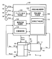
- FIG. 2 is a functional block diagram illustrating an input / output system of an electronic control device provided in the vehicle drive device of FIG. 1 and explaining a main part of a control function by the electronic control device.
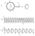
- FIG. 1 it is the schematic explaining the outline
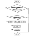
- FIG. 2 is a flowchart for explaining a main part of a control operation according to the present invention of the electronic control device of FIG. 1, that is, a control operation that can accurately calculate the rotation speed of the rotating member and reduce the processing load.
- FIG. 7 is a flowchart for explaining the control operation of the electronic control device when it is desired to prioritize stepped shift control for switching from belt travel to gear travel over switching of rotational speed calculation processing such as sudden deceleration determination in a vehicle. It is a flowchart explaining the control action of the electronic control unit performed while the calculation accuracy of the rotational speed is not recovered during stepped shift control.
- FIG. 1 is a skeleton diagram for explaining a schematic configuration of a vehicle drive device 12 (hereinafter, drive device 12) provided in a vehicle 10 according to an embodiment of the present invention.
- the drive device 12 includes, for example, an engine 14 used as a driving force source for traveling, a torque converter 16 as a fluid transmission device, a forward / reverse switching device 18, and a belt-type continuously variable transmission mechanism 20 (hereinafter referred to as a continuously variable transmission).
- torque (driving force) output from the engine 14 is input to the turbine shaft 26 via the torque converter 16, and this torque is transmitted from the turbine shaft 26 via the gear mechanism 22 (via A second power transmission path L1 transmitted to the output shaft 25 and a second torque transmitted to the output shaft 25 via (via) the continuously variable transmission mechanism 20;
- the power transmission path L2 is provided in parallel, and the power transmission path is switched to one of the first power transmission path L1 and the second power transmission path L2 in accordance with the traveling state of the vehicle.
- the power transmission path L1 corresponds to the power transmission path through which the torque of the driving force source is transmitted via the transmission mechanism of the present invention
- the power transmission path L2 is the torque of the driving force source via the continuously variable transmission mechanism.
- the engine 14 is constituted by an internal combustion engine such as a gasoline engine or a diesel engine.
- the torque converter 16 includes a pump impeller 16p connected to the crankshaft of the engine 14, and a turbine impeller 16t connected to the forward / reverse switching device 18 via a turbine shaft 26 corresponding to an output side member of the torque converter 16.
- a stator impeller 16s connected to a housing 34, which is a non-rotating member, via a one-way clutch (not shown), and transmits power via a fluid.
- a lockup clutch 28 is provided between the pump impeller 16p and the turbine impeller 16t. When the lockup clutch 28 is completely engaged, the pump impeller 16p and the turbine impeller 16t are integrated. Rotated.
- the forward / reverse switching device 18 is composed mainly of a forward clutch C1 and a reverse brake B1 and a double pinion type planetary gear device 30, and a carrier 30c is a turbine shaft 26 of the torque converter 16 and a continuously variable transmission mechanism 20.
- the ring gear 30r is selectively connected to the housing 34 as a non-rotating member via the reverse brake B1, and the sun gear 30s is connected to the small diameter gear 36. Further, the sun gear 30s and the carrier 30c are selectively coupled via the forward clutch C1.
- the forward clutch C1 and the reverse brake B1 correspond to a connection / disconnection device, both of which are hydraulic friction engagement devices that are frictionally engaged by a hydraulic actuator.
- the sun gear 30 s of the planetary gear device 30 is connected to a small-diameter gear 36 constituting the gear mechanism 22.
- the gear mechanism 22 includes the small-diameter gear 36, a large-diameter gear 40 provided so as not to rotate relative to the first counter shaft 38, an idler gear 42, and an input gear 52 formed on the output shaft 25. It consists of An idler gear 42 is provided around the same rotational axis as the first counter shaft 38 so as to be rotatable relative to the first counter shaft 38. Further, a meshing clutch D1 is provided between the first counter shaft 38 and the idler gear 42 to selectively connect and disconnect them.
- the meshing clutch D1 can be engaged with the first gear 48 formed on the first counter shaft 38, the second gear 50 formed on the idler gear 42, and the first gear 48 and the second gear 50 (engagement). And a hub sleeve 61 on which spline teeth are formed, and the hub sleeve 61 is engaged with the first gear 48 and the second gear 50, whereby the first counter The shaft 38 and the idler gear 42 are connected. Further, the meshing clutch D1 further includes a synchromesh mechanism S1 (hereinafter referred to as a synchromesh mechanism S1) as a synchronization mechanism that synchronizes rotation when the first gear 48 and the second gear 50 are engaged.
- a synchromesh mechanism S1 hereinafter referred to as a synchromesh mechanism S1
- the idler gear 42 is meshed with an input gear 52 having a larger diameter than the idler gear 42.
- the input gear 52 is provided on the output shaft 25 disposed on the rotation axis common to the rotation axis of the secondary pulley 56 described later of the continuously variable transmission mechanism 20.
- the output shaft 25 is disposed so as to be rotatable around the rotation axis, and the input gear 52 and the output gear 24 are provided.
- the power transmission state of the first power transmission path is switched according to the engagement state of the forward clutch C1, the reverse brake B1, and the meshing clutch D1.
- the continuously variable transmission mechanism 20 is provided on a power transmission path between the input shaft 32 connected to the turbine shaft 26 and the output shaft 25, and an effective diameter which is an input side member provided on the input shaft 32 is variable.
- a primary pulley 54 (variable pulley 54), a secondary pulley 56 (variable pool 56) having a variable effective diameter which is an output side member, and a transmission belt 58 wound between the pair of variable pulleys 54, 56 Power transmission is performed via a frictional force between the pair of variable pulleys 54 and 56 and the transmission belt 58.
- the primary pulley 54 is a fixed sheave 54a as an input-side fixed rotating body fixed to the input shaft 32, and an input-side movable rotation provided so as not to rotate relative to the input shaft 32 and to move in the axial direction.
- a movable sheave 54b as a body and a hydraulic cylinder 54c that generates thrust for moving the movable sheave 54b in order to change the V-groove width between them are provided.
- the secondary pulley 56 includes a fixed sheave 56a serving as an output-side fixed rotating body, and a movable sheave serving as an output-side movable rotating body provided so as not to rotate relative to the fixed sheave 56a and to be movable in the axial direction. 56b and a hydraulic cylinder 56c for generating a thrust for moving the movable sheave 56b in order to change the V-groove width between them.
- the shaft rotation speed Nout) is continuously changed.
- the speed ratio ⁇ is reduced. That is, the continuously variable transmission mechanism 20 is upshifted.
- the speed ratio ⁇ is increased. That is, the continuously variable transmission mechanism 20 is downshifted.
- the second power transmission path L ⁇ b> 2 is formed in which the torque of the engine 14 is transmitted to the output shaft 25 via the input shaft 36 and the continuously variable transmission mechanism 20. Further, when the belt traveling clutch C2 is released, the second power transmission path L2 is cut off, and torque is not transmitted from the continuously variable transmission mechanism 20 to the output shaft 25.
- the output gear 24 is meshed with a large diameter gear 62 fixed to the second counter shaft 60.
- the second counter shaft 60 is provided with a small-diameter gear 68 that meshes with the large-diameter gear 62 and the differential ring gear 66 of the differential gear 64.
- the differential gear 64 is composed of a differential mechanism, and transmits the power input from the differential ring gear 66 to the left and right drive wheels 70L and 70R while giving an appropriate rotational speed difference to the left and right drive wheels 70L and 70R. Since the differential gear 64 is a known technique, a detailed description thereof is omitted.
- C1 corresponds to the operating state of the forward clutch C1
- C2 corresponds to the operating state of the belt traveling clutch C2
- B1 corresponds to the operating state of the reverse brake B1
- D1 corresponds to the meshing clutch D1.
- “ ⁇ ” indicates engagement (connection)
- “ ⁇ ” indicates release (cutoff).
- the meshing clutch D1 includes a synchronization mechanism S1, and the synchronization mechanism S1 operates when the meshing clutch D1 is engaged.
- This travel pattern corresponds to the gear travel in FIG. 2, and as shown in FIG. 2, the forward clutch C1 and the mesh clutch D1 are engaged (connected), while the belt travel clutch C2 and the reverse brake B1 are released. (Blocked).
- the planetary gear unit 30 constituting the forward / reverse switching device 18 is integrally rotated by engaging the forward clutch C1, the small-diameter gear 36 is rotated at the same rotational speed as the turbine shaft 26. Further, when the meshing clutch D1 is engaged, the counter shaft 38 and the idler gear 42 are connected and rotated integrally. Therefore, when the forward clutch C1 and the meshing clutch D1 are engaged, the first power transmission path L1 is in a connected state, and the power of the engine 14 is transmitted to the torque converter 16, the turbine shaft 26, the forward / reverse switching device 18, This is transmitted to the output shaft 25 and the output gear 24 via the gear mechanism 22, the idler gear 42, and the input gear 52.
- This travel pattern corresponds to the belt travel (high vehicle speed) in FIG. 2, and as shown in the belt travel in FIG. 2, the belt travel clutch C2 is connected, while the forward clutch C1, the reverse brake B1, and the meshing The clutch D1 is disconnected. Since the secondary pulley 56 and the output shaft 25 are connected by connecting the belt running clutch C2, the secondary pulley 56, the output shaft 25, and the output gear 24 are integrally rotated.
- the belt traveling clutch C2 when the belt traveling clutch C2 is connected, the second power transmission path L2 is formed, and the torque of the engine 14 is transmitted to the torque converter 16, the turbine shaft 26, the input shaft 32, and the continuously variable transmission mechanism 20. Via the output shaft 25.
- the meshing clutch D1 is released (disengaged) during the belt travel where the torque of the engine 14 is transmitted via the second power transmission path L2, because the gear mechanism 22 and the like during the belt travel are dragged. This is to prevent the gear mechanism 22 and the like from rotating at a high vehicle speed.
- the gear running is selected in the low vehicle speed range.
- the gear ratio EL (the rotational speed Nin of the turbine shaft 26 / the rotational speed Nout of the output shaft 25) based on the first power transmission path L1 is set to a value larger than the maximum speed ratio ⁇ max of the continuously variable transmission mechanism 20. Yes. That is, the gear ratio EL is set to a value that is not set in the continuously variable transmission mechanism 20. Then, for example, when it is determined that the vehicle travels to the belt traveling because the vehicle speed V increases, the belt traveling is switched.
- the belt travel (medium vehicle speed) in FIG.
- the belt running clutch C2 and the meshing clutch D1 are engaged from the state in which the forward clutch C1 and the meshing clutch D1 corresponding to the gear running are engaged. Transitions to a state transiently. That is, control for switching the forward clutch C1 and the belt traveling clutch C2 is executed. At this time, the power transmission path is switched from the first power transmission path L1 to the second power transmission path L2, and the driving device 12 is substantially upshifted. Then, after the power transmission path is switched, the meshing clutch D1 is released (cut off) (driven input cut off) in order to prevent unnecessary drag and high rotation of the gear mechanism 22 and the like.
- the state is switched from the state in which the belt travel clutch C2 is engaged to the state in which the meshing clutch D1 is engaged in preparation for switching to gear travel. It is done. At this time, the rotation is also transmitted to the sun gear 30s of the planetary gear device 30 via the gear mechanism 22, and control for switching the forward clutch C1 and the belt traveling clutch C2 from this state (control of the forward clutch C1).
- the power transmission path is switched from the second power transmission path L2 to the first power transmission path L1. At this time, the driving device 12 is substantially downshifted.
- FIG. 3 explains the input / output system of the electronic control unit 80 provided in the drive unit 12 for controlling the engine 14, the continuously variable transmission mechanism 20, and the like, and the main part of the control function by the electronic control unit 80. It is a functional block diagram to do.
- the electronic control unit 80 includes, for example, a so-called microcomputer having a CPU, a RAM, a ROM, an input / output interface, and the like, and the CPU uses a temporary storage function of the RAM according to a program stored in the ROM in advance.
- Various controls of the driving device 12 are executed by performing signal processing.
- the electronic control unit 80 controls the output of the engine 14, the shift control of the continuously variable transmission mechanism 20, the belt clamping pressure control, the switching control for appropriately switching the power transmission path of the drive unit 12 to either gear traveling or belt traveling, etc. And is configured separately for engine control, continuously variable transmission control, drive state switching, and the like as necessary.
- a signal representing the rotation angle (position) Acr of the crankshaft detected by the engine rotation speed sensor 82 and the rotation speed (engine rotation speed) Ne of the engine 14 is detected by the turbine rotation speed sensor 84.
- a signal representing the output shaft rotational speed Nout which is the rotational speed of the secondary pulley 56 of the continuously variable transmission mechanism 20 corresponding to the vehicle speed V detected by the output shaft rotational speed sensor 88, and the electrons detected by the throttle sensor 90.
- an engine output control command signal Se for output control of the engine 14 a hydraulic control command signal Sccvt for hydraulic control related to the shift of the continuously variable transmission mechanism 20, and a power transmission path of the drive unit 12
- the hydraulic control command signal Sswt for the forward / reverse switching device 18 (forward clutch C1, reverse brake B1), belt traveling clutch C2, and meshing clutch D1 is output.
- an ignition timing signal for controlling the ignition timing of the engine 14 by the ignition device.
- a command signal or the like for driving a linear solenoid valve (not shown) that regulates pressure is output to the hydraulic control circuit 98.
- the hydraulic control command signal Sswt a command signal for driving each linear solenoid valve for controlling the hydraulic pressure supplied to the forward clutch C1, the reverse brake B1, the belt traveling clutch C2, the synchro mechanism S1, and the like are hydraulic. It is output to the control circuit 98.
- An engine output control unit 100 (engine output control means) shown in FIG. 3 outputs an engine output control command signal Se such as a throttle signal, an injection signal, and an ignition timing signal, for example, for output control of the engine 14, respectively. Output to the device or ignition device.
- the engine output control unit 100 sets a target engine torque Te * for obtaining a required driving force (driving torque) calculated based on, for example, the accelerator opening Acc and the vehicle speed V, and the target engine torque Te * is obtained.
- the fuel injection amount is controlled by the fuel injection device, and the ignition timing is controlled by the ignition device.
- the continuously variable transmission control unit 102 (the continuously variable transmission control means) is a gear ratio of the continuously variable transmission mechanism 20 so that the target gear ratio ⁇ * calculated based on the accelerator opening Acc, the vehicle speed V, the brake signal Bon, and the like. Control ⁇ . Specifically, the continuously variable transmission control unit 102 sets the target speed ratio ⁇ * of the continuously variable transmission mechanism 20 at which the operating point of the engine 14 is on the optimum fuel consumption line while preventing belt slippage of the continuously variable transmission mechanism 20 from occurring.
- the primary command pressure Pintgt as the command value of the primary pressure Pin (target primary pressure Pin *) so that the operating point of the engine 14 becomes the target engine speed Ne * on the optimum fuel consumption line
- a secondary command pressure Pouttgt as a command value (target secondary pressure Pout *) of the secondary pressure Pout is determined, and the primary command pressure Pintgt and the secondary command pressure Pouttgt are output to the hydraulic control circuit 98.
- the switching control unit 104 passes through the first power transmission path L1 through which the torque of the engine 14 is transmitted to the output gear 24 via the gear mechanism 22 and the continuously variable transmission mechanism 20. Then, switching control for switching to belt travel (high vehicle speed) through the second power transmission path L2 in which the torque of the engine 14 is transmitted to the output gear 24 based on the travel state of the vehicle is executed.
- the switching control unit 104 determines to switch to belt traveling during traveling by gear traveling, first, as shown in FIG. 2, the forward clutch C1 is released and the belt traveling clutch C2 is engaged. When the clutch change is completed, the engagement clutch D1 is released. Further, when it is determined to switch to gear traveling during traveling by belt traveling, as shown in FIG. 2, first, the engagement clutch D1 is engaged, and when engagement of the engagement clutch D1 is completed, the belt traveling clutch C2 is engaged. And the forward clutch C1 is engaged.
- the gear ratio changes stepwise (stepwise, stepwise) between the gear ratio EL of the gear mechanism 22 and the gear ratio ⁇ of the continuously variable transmission mechanism 20.
- FIG. 4 is a schematic diagram for explaining the outline of each rotation speed sensor 72 that detects the rotation speed N of a predetermined rotation member K including the crankshaft of the engine 14, the input shaft 32, the output shaft 25, and the drive wheels 70. is there.
- each rotating member K is formed with a plurality of teeth 74 arranged along the circumferential direction, and a recess 75 is formed between the teeth 74 in association with this. Yes.
- the rotation speed sensor 72 is provided at a position facing the teeth 74 formed on the rotation member K.
- an electromagnetic pickup type, Hall element type, MRE (MagneticMagnResistance Element) type sensor or the like is employed.
- the rotation member K rotates, so that the rotation speed sensor 72 changes the air gap between the rotation member K and the teeth 74 and the recesses 75 alternately.
- An AC voltage whose frequency changes corresponding to the rotation speed of the member K is output from the rotation speed sensor 72.
- the AC voltage is supplied to the electronic control unit 80 as a rotation speed signal, and the supplied AC voltage is generated by the electronic control unit 80 into a rectangular pulse signal P as shown in FIG.
- the sensor circuit (IC) includes a Hall element or MRE.
- the rotating member K rotates, the magnetic field applied to the sensor circuit (IC) is reduced. Therefore, an alternating voltage whose frequency changes corresponding to the rotation speed of the rotating member K is generated, and the alternating voltage is converted into a rectangular pulse signal P as shown in FIG.
- the pulse signal P is supplied to the electronic control unit 80 as a rotation speed signal.
- 16 teeth 74 of approximately the same shape and approximately equal intervals, teeth a to p, are formed by stamping or the like, resulting in 16 teeth between each tooth.
- a concave portion 75 of the concave portion a to the concave portion p is formed as a detection target.
- the electronic control unit 80 uses the pulse signal P as shown in FIG. 4 (b) for the intervals (pulse intervals) of the pulse signals Pa to Pp corresponding to the teeth a to teeth p and the recesses a to p.
- Each pulse interval T [-i] (hereinafter referred to as pulse interval T [-i]) is calculated as needed.
- each pulse interval T [-i] is a period from the rise of the pulse signal P to the rise of the next pulse signal P. That is, in this embodiment, the pulse interval T [-i] is a time interval (interrupt interval: pulse interrupt interval) between the pulse signals P corresponding to the rising edge of each pulse signal P.
- the pulse signals Pa to Pp become high (Hi) at positions where the teeth a to p are substantially opposite to the rotational speed sensor 72, and the concave portions a to p are rotated at the rotational speed.
- Each pulse signal Pa to Pp becomes low at a position substantially opposite to the sensor 72.
- the electronic control unit 80 incorporates a 1/2 frequency dividing circuit 76, and the divided pulse signal P 1 / obtained by dividing the pulse signal P by 1/2 from the 1/2 frequency dividing circuit 76. 2 is generated.
- FIG. 4C shows a divided pulse signal P 1/2 of the pulse signal P divided by the 1 ⁇ 2 divider circuit 76. As shown in FIG. 4C, since one divided pulse signal P 1/2 is generated for two pulse signals P, the pulse interval T [-i] is also equal to the pulse interval T [ Longer than -i].
- the rotation speed calculation unit 106 rotates the rotating member K using each pulse interval T [-i] calculated and stored (accumulated) every time the pulse signal P and the divided pulse signal P1 / 2 are detected.
- the speed N is calculated.
- the calculation method of the rotation speed N of the rotating member K by the rotation speed calculation unit 106 will be specifically described.
- the rotation speed calculation unit 106 calculates the rotation speed N every calculation period T set in advance.
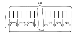
- the rotation speed calculation unit 106 determines the number of pulses of the pulse signal P generated at the time interval (that is, the calculation cycle T) between the current calculation time and the previous calculation time (that is, the number of teeth that have passed through the rotation speed sensor 72). ) And the pulse interval T [-i], and the rotational speed N is calculated based on the number of pulses and each pulse interval T [-i]. Specifically, it is calculated based on the following formula (1).
- A indicates the number of pulses of the pulse signal P generated during the calculation cycle T, and M is the total number (for example, 16) of teeth 74 formed along the circumference of the rotating member K. ).
- the past A pulse intervals T [-i] are sequentially stored and accumulated in the RAM of the electronic control unit 80 as a history of past pulse intervals.
- N (A / M) / (T [-A + 1] + T [-A + 2] + .. + T [-1] + T [0]) (1)
- the denominator (T [-A + 1] + T [-A + 2] + .. + T [-1] + T [0]) of the equation (1) is shown in FIG. Specifically, this is the total Ttotal of the past A pulse intervals T [-i] including the pulse interval T [0] between the previous pulse generation time and the current pulse generation time. Then, by dividing (A / M) by the total Ttotal, the rotational speed N of the rotating member K at the current rotational speed calculation time is calculated. As described above, when a pulse is generated between the previous rotational speed calculation time and the current rotational speed calculation time, the pulse interval T [0 between the previous pulse generation time and the current pulse generation time is as follows.
- the rotational speed N of the rotating member K at the time of the current rotational speed calculation is calculated using a history of a plurality of previous (A) pulse intervals.
- a so-called interrupt operation is performed to calculate the pulse interval T [-i].
- the calculation of the rotational speed N of the rotating member K based on the pulse signal P is defined as a calculation without frequency division in this embodiment. This calculation without frequency division corresponds to the rotation speed calculation processing based on the pulse signal of the present invention.
- the rotation speed calculation unit 106 for example, the number of divided pulse signals P1 / 2 generated at the time interval between the current calculation time and the previous calculation time (that is, the calculation cycle T), and the pulse interval T [ -i] is read, and the rotational speed N is calculated based on the number of divided pulses and each pulse interval T [-i]. Specifically, it is calculated based on the following formula (2).
- B indicates the number of divided pulses P1 / 2 generated during the calculation period T.
- the past B pulse intervals T [-i] are sequentially stored and accumulated in the RAM of the electronic control unit 80 as a history of past pulse intervals.
- N (B / (M / 2)) / (T [-B + 1] + T [-B + 2] +... + T [-1] + T [0]) (2)
- the denominator (T [-B + 1] + T [-B + 2] + .. + T [-1] + T [0]) in equation (2) is the previous frequency division pulse generation time and the current frequency division pulse generation. This is the total Ttotal of B pulse intervals T [-i] in the past including the pulse interval T [0] between the time points. Then, by dividing (B / (M / 2)) by the total Ttotal, the rotational speed N of the rotating member K at the current rotational speed calculation time is calculated.
- the rotational speed N of the rotating member K at the time of the current rotational speed calculation is calculated using a history of a plurality of previous (B) pulse intervals including the previous pulse interval T [0].
- the rotation speed N is calculated, every time the divided pulse signal P 1/2 is generated, the number of divided pulses being counted is incremented by one, and the detected divided pulse signal P 1 / A so-called interrupt operation is performed to calculate a pulse interval T [-i] between 2 and the previously detected divided pulse signal P1 / 2 .
- Calculation of the rotational speed N of the rotating member K based on the divided pulse signal P1 / 2 is defined as an operation with division in this embodiment. This calculation with frequency division corresponds to the rotation speed calculation processing based on the frequency division pulse signal of the present invention.
- the rotation speed calculation unit 106 appropriately switches between the calculation without division and the calculation with division according to the rotation speed N. Specifically, the rotation speed calculation unit 106 ensures calculation accuracy of the rotation speed N by executing a calculation without frequency division in the low rotation region. Moreover, the rotational speed calculation part 106 reduces the processing load of the electronic control apparatus 80, ensuring the calculation precision of the rotational speed N by performing a calculation with a frequency division in a high rotation area
- the rotation speed calculation unit 106 functionally includes a rotation speed determination unit 108 and a switching completion determination unit 110.
- the rotation speed calculation unit 106 performs both of the calculation without division and the calculation with division from the state in which only the calculation with division is executed in the previous time step or only the calculation with division is executed. It is determined whether or not the flag that is set in the state (i.e., the transition transition period to the operation without division) is ON (flag ON). In other words, when the flag is on, only the operation with division is executed, or the state where only the operation with division is executed, and the state where both the operation without division and the operation with division are executed. Become. On the other hand, in the flag off state, only the operation without division is executed, or the state where only the operation without division and the operation with division are executed from the state where only the operation without division is executed (Transition transition period to operation with division).
- the flag is switched on when the calculation with no division and the calculation with division is executed in the previous time step in the flag-off state when the calculation is switched to the calculation with division. Further, the flag is switched off when the flag is turned on when the calculation without division and the calculation with division are executed in the previous time step to the calculation without division.
- the flag is set to off when the vehicle starts or when the vehicle stops.
- the rotation speed determination unit 108 determines whether or not the rotation speed N calculated immediately before is not more than a preset first reference value ⁇ in a flag-on state. When the rotation speed N is less than or equal to the first reference value ⁇ , the switching completion determination unit 110 determines whether or not to switch only to no division calculation. A specific control operation of the switching completion determination unit 110 will be described later. On the other hand, when the rotation speed N exceeds the first reference value ⁇ , the rotation speed calculation unit 106 performs only the calculation with frequency division.
- the first reference value ⁇ is obtained in advance based on experiments or the like, and is set to a value (threshold value) at which the calculation accuracy of the calculation with division starts to decrease.
- the rotation speed determination unit 108 determines whether or not the rotation speed N is equal to or greater than a preset second reference value ⁇ in a flag-off state.
- the switching completion determination unit 110 determines whether or not to switch to only calculation with frequency division. A specific control operation of the switching completion determination unit 110 will be described later.
- the rotation speed calculation unit 106 executes only a calculation without frequency division.
- the second reference value ⁇ is obtained in advance based on experiments or the like, and is set to a value at which the calculation accuracy of the calculation with division is almost the same as the calculation accuracy of the calculation without division.
- the switching completion determination unit 110 is performed. Determines whether a condition for switching to a calculation without frequency division or a calculation with frequency division is satisfied.
- the rotation speed N decreases during calculation of the rotation speed N by the calculation with frequency division and becomes equal to or less than the first reference value ⁇ , the calculation accuracy of the rotation speed N starts to decrease, so the calculation accuracy of the rotation speed N is ensured. Therefore, it is preferable to switch to a calculation without frequency division.
- the calculation is switched to the calculation without division when the first reference value ⁇ is reached, there is a difference between the rotation speed Na by the calculation without division and the rotation speed Nb by the calculation with division. is there. In such a case, for example, when switching to the no-frequency division calculation is performed during the switching control for switching the first power transmission path L1 and the second power transmission path L2, the switching control is continued based on the separated rotational speed N.
- the rotation speed calculation unit 106 is the rotation speed N is equal to or less than the first reference value ⁇ in a state where only the calculation with division is executed, or is equal to or more than the second reference value ⁇ in the state where only the calculation without division is executed.
- the calculation method is not immediately switched, and the calculation method is executed when a condition for switching the calculation method described later by the switching completion determination unit 110 is satisfied by executing the calculation without division and the calculation with division in parallel. Switch.
- a predetermined value ⁇ 1 which is set in advance, it is determined that a condition for switching the calculation method of the rotational speed N (hereinafter, switching completion condition) is satisfied.
- the predetermined value ⁇ 1 is set in advance based on experiments and the like, and is a small value at which the rotation speed Na (calculation without frequency division) and rotation speed Nb (calculation with frequency division) calculated by each calculation can be regarded as substantially the same value. Is set to
- the switching completion determination unit 110 replaces the switching completion condition with the control target value of the continuously variable transmission mechanism 20 obtained based on the rotation speed Na (for example, the engine rotation speed Ne) calculated by the no-frequency division calculation.
- the difference from the control target value of the continuously variable transmission mechanism 20 calculated based on the rotational speed Nb calculated by the operation with frequency division is equal to or less than a predetermined value set in advance, the switching completion condition is satisfied. It may be determined as a thing.
- the difference between the control target values is set in advance based on experiments or the like.
- the difference between the control target values is equal to or less than a predetermined value set in advance
- the difference between the rotation speed Na calculated by the no-frequency division calculation and The difference ⁇ N (
- ) from the rotational speed Nb calculated by the operation with frequency division is set to a value that is equal to or less than the predetermined value ⁇ 1.
- the switching completion determination unit 110 calculates the target primary pressure Pin * a of the hydraulic cylinder 54c of the primary pulley 54 based on the rotation speed Na calculated by the calculation without division and the rotation calculated by the calculation with division.
- a switching completion condition is set. It may be determined that it has been established.
- the switching completion determination unit 110 sets the target secondary pressure Pout * a of the hydraulic cylinder 56c of the secondary pulley 56 based on the rotation speed Na calculated by the non-frequency division calculation and the rotation speed Nb calculated by the frequency division calculation.
- the hydraulic pressure difference ⁇ Pout * (
- ) with respect to the target secondary pressure Pout * b of the hydraulic cylinder 56c is less than or equal to a predetermined value ⁇ 3 set in advance, the switching completion condition is satisfied May be determined.
- ) is set to a value that is equal to or less than the predetermined value ⁇ 1. Therefore, even if the shift control is continued based on the rotational speed N that is switched during the shifting of the continuously variable transmission mechanism 20, the value is low enough not to cause a problem such as a shock.
- the switching completion determination unit 110 replaces the switching completion condition with the target hydraulic pressure Pc1 * a of the forward clutch C1 obtained based on the rotation speed Na calculated by the non-division calculation and the calculation with division.
- the hydraulic pressure difference ⁇ Pc1 * (
- ) with respect to the target hydraulic pressure Pc1 * b of the forward clutch C1 obtained based on the calculated rotational speed Nb is equal to or less than a predetermined value ⁇ 4. Then, it may be determined that the switching completion condition is satisfied.
- the switching completion determination unit 110 sets the target hydraulic pressure Pc2 * a of the belt travel clutch C2 obtained based on the rotation speed Na calculated by the no-frequency division calculation and the rotation speed Nb calculated by the frequency division calculation.
- the hydraulic pressure difference ⁇ Pc2 * (
- ) which is obtained based on the target hydraulic pressure Pc2 * b of the belt travel clutch C2 becomes equal to or less than a predetermined value ⁇ 5
- ) is set to a value that is equal to or less than the predetermined value ⁇ 1. For this reason, even if the control is continued based on the rotation speed N switched during the switching control, the value is low enough not to cause a problem such as a shock.
- the switching completion determination unit 110 determines whether a predetermined time T ⁇ that has been set in advance has elapsed with reference to that point. It may be determined whether or not the switching completion condition is satisfied when a predetermined time T ⁇ has elapsed instead of the switching completion condition.
- the predetermined time T ⁇ is set in advance based on experiments or the like.
- the predetermined time T ⁇ elapses after the rotational speed N reaches the first reference value ⁇
- the difference ⁇ N (
- ) with the rotational speed Nb calculated by the calculation is set to a value that is equal to or less than the predetermined value ⁇ 1.
- the predetermined time T ⁇ corresponds to the first predetermined time of the present invention.
- the switching completion determination unit 110 determines whether a predetermined time T ⁇ that has been set in advance has elapsed with reference to that point. It may be determined whether or not. The switching completion determination unit 110 may determine that the switching completion condition is satisfied when a predetermined time T ⁇ has elapsed in addition to the switching completion condition.
- This predetermined time T ⁇ is set in advance based on experiments or the like, and when the rotation speed N reaches the second reference value ⁇ , when the predetermined time T ⁇ elapses, the rotation speed Na calculated by the no-frequency division calculation,
- the difference ⁇ N (
- ) with respect to the rotational speed Nb calculated by the operation with circumference is set to a value that is equal to or less than the predetermined value ⁇ 1.
- the predetermined time T ⁇ corresponds to the second predetermined time of the present invention.
- the establishment of the switching completion condition is determined based on any one or more of the specific modes of the switching determination by the switching completion determination unit 110 described above.
- the rotation speed calculation unit 106 stops the calculation without dividing and the calculation with dividing performed in parallel. Then, switch to one of the calculation methods.
- the switching control unit 104 switches between the first power transmission path L1 and the second power transmission path L2. (Switching control) is not executed.
- the rotation speed calculation unit 106 calculates the rotation speed N based on the calculation with frequency division.
- the rotation speed calculation unit 106 executes the calculation without division and the calculation with division in parallel. While the calculation without frequency division and the calculation with frequency division are executed in parallel, the calculation accuracy of the rotational speed N based on the frequency division pulse signal P1 / 2 is not ensured, so that the switching control is not executed.
- the rotation speed calculation unit 106 switches the calculation method of the rotation speed N to calculation without division, and calculates the rotation speed N by the calculation without division. At this time, the rotation speed calculation unit 106 switches the flag to flag off.
- the continuously variable transmission control unit 102 and the switching control unit 104 execute control using the rotation speed N calculated by the no-frequency division calculation.
- the rotational speed N is high high rotation region than the first reference value alpha, dividing there operation is performed, as appropriate due to the high rotational speed N frequency dividing pulse signal P 1/2 also Generated. Therefore, the calculation accuracy of the rotation speed N in the high rotation region is also ensured. Further, in the operation with frequency division, an interrupt operation is executed every time the divided pulse signal P1 / 2 is generated. Therefore, the interrupt operation is executed as compared with the case where the interrupt operation is executed every time the pulse signal P is generated. The number of calculations is also reduced, and the processing load on the electronic control unit 80 is also reduced.
- the rotation speed calculation unit 106 calculates the rotation speed N based on the no-frequency division calculation. In this state, when the rotation speed increases and the rotation speed N increases to the second reference value ⁇ , the rotation speed calculation unit 106 executes the calculation without division and the calculation with division in parallel. During this time, switching control is not executed. Further, in parallel with this, switching completion determination is performed as needed, and when it is determined that the switching completion condition is satisfied, the rotation speed calculation unit 106 switches the calculation method of the rotation speed N to calculation with frequency division, The rotational speed N is calculated based on the calculation with frequency division. At this time, the rotation speed calculation unit 106 switches the flag to flag on. The continuously variable transmission control unit 102 and the switching control unit 104 execute control using the rotational speed N calculated by the operation with frequency division.
- the calculation without frequency division is executed and the calculation accuracy of the rotational speed N is ensured.
- a calculation with frequency division is also executed in addition to the calculation without frequency division, and a switching completion determination is executed based on the calculation result. Timing is optimized, and problems such as shocks are prevented.
- the switching completion determination unit 110 determines that the switching completion condition is satisfied and is switched to the calculation with frequency division, so that the processing load of the electronic control device 80 is reduced and the calculation accuracy of the rotational speed N is also ensured.
- FIG. 6 is a flowchart for explaining a main part of the control operation of the electronic control unit 80, specifically, a control operation in which the rotational speed N of the rotating member K is accurately calculated and the processing load is reduced. This flowchart is repeatedly executed while the vehicle is traveling.
- step S1 (hereinafter, step is omitted) corresponding to the rotation speed calculation unit 106, it is determined whether or not the flag is on. That is, whether the operation with division is being executed, or the state where both the operation without division and the operation without division are being executed (transitional period when switching to the operation without division) Is determined.
- S1 is affirmed
- S2 corresponding to the rotation speed determination unit 108
- S6 corresponding to the rotation speed calculation unit 106, the rotation speed N is calculated by calculation with frequency division.
- the switching completion determination unit 110 determines whether or not the switching completion condition is satisfied.
- a predetermined time T ⁇ has elapsed since the rotational speed N has reached the first reference value ⁇ .
- step S9 corresponding to the rotational speed determination unit 108, it is determined whether or not the previously calculated rotational speed N is greater than or equal to the second reference value ⁇ .
- the rotation speed N is calculated by the calculation without frequency division in S13 corresponding to the rotation speed calculation unit 106.
- the switching completion determination unit 110 determines whether or not the switching completion condition is satisfied.
- a predetermined time T ⁇ has elapsed since the rotation speed N has reached the second reference value ⁇ .
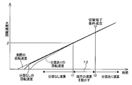
- FIG. 7 is a time chart showing the operation result based on the flowchart of FIG. 6, and shows an example in which the rotation speed N increases from zero rotation (flag off state).
- the calculation is started from the flag off state.
- the horizontal axis indicates time (elapsed time), and the vertical axis indicates the rotation speed N.
- the rotational speed N is calculated based on the no division calculation, and the rotational speed N calculated by the no division calculation indicated by the solid line is The rotation speed is relatively close to the actual rotational speed indicated by the one-dot chain line.
- the calculation result when the rotational speed N is calculated based on the operation with frequency division is exemplarily shown by a broken line. As shown in the figure, when the rotation speed N is calculated based on the calculation with frequency division in this low rotation region, there is a deviation from the actual rotation speed as indicated by a broken line.
- both the calculation without division and the calculation with division are executed until the switching completion condition is satisfied, and the calculation is performed by these calculations.
- the rotation speed Na (calculation without frequency division)
- the rotation speed Nb (calculation with frequency division)
- the rotational speed N is calculated based on the calculation with frequency division. After the switching completion condition is satisfied, even the calculation with frequency division is substantially equal to the actual rotation speed. That is, the calculation accuracy is ensured even in the calculation with frequency division. Further, by executing the operation with frequency division, the number of interrupt operations is reduced, and the processing load on the electronic control unit 80 is reduced.
- FIG. 8 is a time chart showing the operation result based on the flowchart of FIG. 6, and shows an example in which the rotational speed N decreases from the rotational speed region (flag on state) exceeding the first reference value ⁇ .
- the rotational speed N is calculated based on the calculation with frequency division.
- a result substantially equal to the actual rotational speed can be obtained even with the calculation with frequency division. That is, the calculation accuracy is ensured even in the calculation with frequency division.
- an area is set in which a calculation without division and a calculation with division are executed simultaneously in order to execute the switching completion determination.
- the switching control is executed.
- it may be desirable to start switching control promptly For example, when the vehicle 10 is suddenly decelerated or suddenly stopped during belt travel, it is desirable to quickly switch to gear travel. Further, even when switching by the driver's intention such as kick down or manual downshift, if the switching is delayed, the driver feels uncomfortable, so it is desirable to execute switching control promptly.
- the rotation speed calculation unit 106 gives priority to the start of the switching control over the switching timing of the calculation method, does not execute the switching completion determination, and immediately switches the calculation method to start the switching control.
- the belt between the pulleys 54 and 56 of the continuously variable transmission mechanism 20 and the transmission belt 58 due to the fact that the switching of the calculation method is not executed at the optimal timing during the switching control giving priority to the switching control. Slip may occur.
- the durability of the continuously variable transmission mechanism 20 decreases. Therefore, when priority is given to switching control, the continuously variable transmission control unit 102 prevents the transmission belt 58 from slipping by increasing the hydraulic pressure of the hydraulic cylinders 54c, 56c of the pulleys 54, 56.
- the switching control is executed based on the rotational speed N calculated by the switched calculation method. However, the switching completion determination is not executed, and the rotational speed N It is hard to say that the calculation accuracy has recovered. Therefore, the switching control unit 104 can execute switching control not based on the rotational speed N (special switching control) instead of switching control based on the rotational speed N while the calculation accuracy of the rotational speed N is not recovered. . Specifically, the switching control unit 104 executes sweep control for increasing or decreasing the command oil pressure at a preset constant gradient, or feedforward control for controlling the oil pressure based on the command oil pressure set in advance. . These are controls that do not use the rotational speed N. When the calculation accuracy of the rotation speed N has been restored, the switching control unit 104 executes a hydraulic pressure map, model base control, or feedforward control using the rotation speed N.
- FIG. 9 illustrates the control operation of the electronic control unit 80 applied when switching control is prioritized over switching of the above-described calculation methods, such as sudden deceleration during belt running or manual downshift by the driver. It is a flowchart to do.
- S10 corresponding to the rotation speed determination unit 108 and the switching completion determination unit 110, it is determined whether the rotation speed N calculated last time is equal to or less than the first reference value ⁇ and whether the switching completion condition is not satisfied.
- S10 is affirmed, it progresses to S11, and when S10 is denied, it returns.
- S11 corresponding to the switching control unit 104, it is determined whether or not there is a request to prioritize switching control over switching of the calculation method.
- This switching control is given priority when, for example, it is judged that the vehicle is suddenly decelerating or suddenly stopped, and further when a low gear request is output due to the driver's intention such as kickdown shift or manual down.
- the sudden deceleration and sudden stop of the vehicle are determined, for example, when the brake pedal depression amount exceeds a predetermined value, or when the change rate of the brake pedal depression amount exceeds a predetermined value. Is done.
- the kick down shift is determined when the amount of depression of the accelerator opening Acc or the change speed of the depression exceeds a predetermined value set in advance.
- the manual downshift is determined when the lever position Psh is operated to the downshift side. If S11 is configured, the process proceeds to S12, and if S11 is negative, the process returns.
- FIG. 10 is a flowchart for explaining the control operation of the electronic control unit 80 that is executed when the calculation accuracy of the rotational speed N is not recovered during the switching control, such as when switching control is prioritized.
- S20 corresponding to the switching control unit 104 and the switching completion determination unit 110, it is determined whether switching control is being performed and the calculation accuracy of the rotational speed N has not been recovered.
- the state in which the calculation accuracy of the rotational speed N is not recovered corresponds to a case where the calculation method is not switched at the optimal switching timing, for example, when switching control is prioritized.
- S20 is denied, this routine is ended, and when S20 is affirmed, the process proceeds to S21.
- special switching control that does not use the rotational speed N is performed.
- the control is switched from a hydraulic control based on a hydraulic pressure map (indicated pressure map) using the rotational speed N as a parameter to a constant sweep control in which the hydraulic pressure is increased or decreased at a predetermined gradient in advance.
- the model base control based on the rotational speed N is switched to the feedforward control that does not use the information on the rotational speed N.
- the feedback control based on the rotational speed N is switched to the feedforward control that does not use the rotational speed N information. Note that this control can also be performed in a state where the calculation without frequency division and the calculation with frequency division are performed in parallel.
- the calculation without frequency division is executed based on the pulse signal P generated by the rotation speed sensor 72. .
- the operation with frequency division is executed based on the divided pulse signal P 1/2 obtained by dividing the pulse signal P.
- the rotation by the rotation speed sensor 72 is performed while the calculation process is started based only on the pulse signal P from the state where the calculation process is performed based only on the divided pulse signal P1 / 2. Since the calculation accuracy of the speed N is not ensured, the switching control for switching the power transmission path is not executed during this period, so that the shock generated during the switching control or the durability of the friction material constituting the clutches C1 and C2 is reduced. Can be prevented.
- the 1/2 divider circuit 76 is used to generate the divided pulse signal P1 / 2.
- a 1/4 divider circuit is used instead of the 1/2 divider circuit 76. It can be changed as appropriate, for example.
- a 1 ⁇ 4 divider circuit may be added.
- the 1 ⁇ 2 divider circuit 76 is incorporated in the electronic control unit 80. However, it may be provided as a separate IC.
- the frequency may be controlled by software.
- the vehicle drive device 12 includes the continuously variable transmission mechanism 20 and the gear mechanism 20 in parallel.
- the present invention can be applied as appropriate even in other embodiments. .
- the present invention can be appropriately applied as long as it has a configuration for calculating a rotational speed at any time using a rotational speed sensor, such as a conventional automatic transmission or an HV type driving device.
- the first predetermined time ⁇ and the second predetermined time ⁇ are different values, but the numerical values are not necessarily different and may be the same value.
Landscapes
- Engineering & Computer Science (AREA)
- General Engineering & Computer Science (AREA)
- Mechanical Engineering (AREA)
- Physics & Mathematics (AREA)
- General Physics & Mathematics (AREA)
- Control Of Transmission Device (AREA)
Abstract
所定の回転部材の回転速度が低回転となっても精度良く回転速度を算出でき、且つ、処理負荷を低減できる車両の制御装置を提供する。 回転速度Nが第1基準値α以下の低回転領域では、回転速度センサ(72)によって生成される全てのパルス信号Pに基づいて分周なし演算が実行され、低回転領域であっても回転速度Nの演算精度を確保できる。一方、回転速度Nが第2基準値β以上の高回転領域では、パルス信号Pを分周した分周パルス信号P1/2 に基づいて分周あり演算が実行され、回転速度Nの演算精度を確保することができる。 また、前記パルス信号に基づく回転速度と前記分周パルス信号に基づく回転速度との回転速度差が所定値以上であるときは、回転速度の演算精度が確保されない状態であるため、動力伝達経路の切り替えを実行しないことで、切り替え中に発生するショックやクラッチ機構を構成する摩擦材の耐久性低下等を防止できる。
Description
本発明は、車両の制御装置に係り、特に、車両に備えられる所定の回転部材の回転速度を検出する回転速度センサの検出精度向上に関するものである。
自動変速機のクラッチツウクラッチ制御やトルクコンバータのロックアップ制御をはじめとした車両の各種制御において、エンジンのエンジン回転速度、変速機の入力軸回転速度、変速機の出力軸回転速度、タービン軸のタービン回転速度等が逐次検出され、検出された回転速度に基づいて各種制御が実行される。これらの各種制御を精度良く実行するには、各種回転部材の回転速度を精度良く検出する必要がある。
特許文献1には、エンジンの駆動力によって回転する入力軸に接続される入力軸要素の回転速度と、それにベルトを介して接続される出力軸要素の回転速度とをそれぞれ周波数で検出し、検出された前記入力軸要素と出力軸要素とについての周波数の面積をそれぞれ算出し、算出された前記入力軸要素と出力軸要素についての周波数の面積に基づいて入力軸要素と出力軸要素の少なくともいずれかと動力伝達要素の間の滑り量を検知する技術が開示されている。この入力軸要素の回転速度ならびに出力軸要素の回転速度の検出は、具体的には、該当する回転部材の軸回りに複数個の歯が形成され、単位時間に通過する歯数を電磁ピックアップ等のセンサで読みとることで算出している。また、特許文献2乃至特許文献4についても、同様の方法で各種回転部材の回転速度が算出されている。
ところで、常用の回転速度領域では単位時間に歯が通過することでセンサからパルス信号が出力されるが、回転部材の回転速度が低回転になると、単位時間の間に歯が通過せずパルス信号が出力されないことが考えられる。このような場合には、センサによる回転速度の検出精度が悪くなる。これに対して、回転部材に形成される歯数を増加すれば検出精度も向上するが、パルス信号が出力される毎に所定の割り込み演算処理が実行されるため、歯数が増えると特に高回転領域において電子制御装置の処理負荷が増加するという問題が生じる。
本発明は、以上の事情を背景として為されたものであり、その目的とするところは、車両に備えられる所定の回転部材の回転速度が低回転となっても精度良く回転速度を算出でき、且つ、電子制御装置の処理負荷を低減できる車両の制御装置を提供することにある。
上記目的を達成するための、第1発明の要旨とするところは、(a)所定の回転部材の回転速度に応じてパルス信号を生成する回転速度センサを備える車両において、生成されたそのパルス信号に基づいてその所定の回転部材の回転速度を算出する車両の制御装置であって、(b)前回算出された前記回転部材の回転速度が予め設定されている第1基準値以下である場合、前記回転速度センサによって生成されるパルス信号に基づいて回転速度演算処理を実行し、(c)前回算出された前記回転部材の回転速度が予め設定されている第2基準値以上である場合、前記回転速度センサによって生成されるパルス信号を分周した分周パルス信号に基づいて回転速度演算処理を実行するものであり、(d)前記車両は、駆動力源のトルクが伝達される入力軸と出力軸との間に介挿される無段変速機構と、その無段変速機構に対して並列に設けられている伝動機構と、前記無段変速機構を介して前記駆動力源のトルクが伝達される動力伝達経路と前記伝動機構を介して前記駆動力源のトルクが伝達される動力伝達経路とに選択的に切替えるクラッチ機構とを、備え、(e)前記所定の回転部材の回転速度が前記第1基準値以下の場合、または、前記回転速度が第2基準値以上の場合において、前記パルス信号に基づく回転速度と前記分周パルス信号に基づく回転速度との回転速度差が所定値以上であるときは、前記無段変速機構を介した動力伝達経路と、前記伝動機構を介した動力伝達経路との切り替えを実行しないことを特徴とする。
このようにすれば、回転速度が第1基準値以下の低回転領域では、回転速度センサによって生成されるパルス信号に基づいて回転速度演算処理が実行される。このように、回転速度センサによって生成される全てのパルス信号に基づいて演算処理が実行されるので、低回転領域であっても回転速度の演算精度を確保できる。一方、回転速度が第2基準値以上の高回転領域では、パルス信号を分周した分周パルス信号に基づいて回転速度演算処理が実行される。高回転領域では回転部材が高回転で回転するので、パルス信号を分周した分周パルス信号であっても、その分周パルス信号は頻繁に生成されるため、回転速度の演算精度を確保することができる。また、分周パルス信号が生成される度に割り込み演算処理が実行されるため、パルス信号が出力される度に割り込み演算が実行される場合に比べて、演算の処理負荷を低減することができる。これより、回転部材に形成される歯数を増加しても処理負荷が低減され、低回転領域において回転速度の演算精度を確保できる。また、所定の回転部材の回転速度が第1基準値以下、または、第2基準値以上において、パルス信号に基づく回転速度と分周パルス信号に基づく回転速度との回転速度差が所定値以上である場合には、回転速度センサによる回転速度の演算精度が確保されない状態であるため、動力伝達経路の切り替えを実行しないことで、切り替え中に発生するショックやクラッチ機構を構成する摩擦材の耐久性低下等を防止できる。
また、第2発明の要旨とするところは、第1発明の車両の制御装置において、前記所定の回転部材の回転速度が前記第1基準値以下となってから第1所定時間が経過していない場合、または、前記回転速度が前記第2基準値以上となってから第2所定時間が経過していない場合、前記切り替えを実行しないことを特徴とする。回転部材の回転速度が低下して第1基準値になった直後、または回転速度が増加して第2基準値となった直後は、パルス信号に基づく回転速度と分周パルス信号に基づく回転速度との回転速度差が所定値以上であるため、回転速度センサによる回転速度の演算精度が確保されない。そのため、前記回転速度が第1基準値以下になってから第1所定時間が経過しない間、または、前記回転速度が第2基準値以上になってから第2所定時間が経過しない間のように、パルス信号に基づく回転速度と分周パルス信号に基づく回転速度との回転速度差が所定値以上である場合には、回転速度センサによる回転速度の演算精度が確保されない状態であるため、前記切り替えを実行しないことで、切り替え中に発生するショックやクラッチ機構を構成する摩擦材の耐久性低下を防止できる。
また、第3発明の要旨とするところは、第1発明の車両の制御装置において、前記無段変速機構を介した動力伝達経路と、前記伝動機構を介した動力伝達経路との切り替えを優先する要求がある場合には、前記切り替えを実行することを特徴とする。このように、動力伝達経路を切り替える要求がある場合には、動力伝達経路の切り替えを優先して実行することで、切り替えの遅れや運転者に与える違和感を防止できる。
また、第4発明の要旨とするところは、第3発明の車両の制御装置において、前記無段変速機構を介した動力伝達経路と、前記伝動機構を介した動力伝達経路との切り替えを優先して実行する場合には、前記パルス信号に基づいて回転速度演算処理を実行することを特徴とする。このようにすれば、パルス信号に基づいて回転速度演算処理が実行されるので、切り替えの遅れを防止できる。
以下、本発明の実施例を図面を参照しつつ詳細に説明する。なお、以下の実施例において図は適宜簡略化或いは変形されており、各部の寸法比および形状等は必ずしも正確に描かれていない。
図1は、本発明の一実施例である車両10に備えられる車両用駆動装置12(以下、駆動装置12)の概略構成を説明するための骨子図である。駆動装置12は、例えば走行用の駆動力源として用いられるエンジン14と、流体式伝動装置としてのトルクコンバータ16と、前後進切替装置18と、ベルト式無段変速機構20(以下、無段変速機構20)と、ギヤ機構22(本発明の伝動機構)と、駆動輪70に動力伝達可能な出力ギヤ24が形成されている出力軸25と、デフギヤ64とを、含んで構成されている。駆動装置12にあっては、エンジン14から出力されるトルク(駆動力)がトルクコンバータ16を経由してタービン軸26に入力され、このトルクがタービン軸26からギヤ機構22を介して(経由して)出力軸25に伝達される第1の動力伝達経路L1と、前記タービン軸26に入力されたトルクが無段変速機構20を介して(経由して)出力軸25に伝達される第2の動力伝達経路L2とを並列に備えており、車両の走行状態に応じて、動力伝達経路が第1の動力伝達経路L1および第2の動力伝達経路L2の何れか一方に切り替えられるように構成されている。なお、この動力伝達経路L1が、本発明の伝動機構を介して駆動力源のトルクが伝達される動力伝達経路に対応し、動力伝達経路L2が無段変速機構を介して駆動力源のトルクが伝達される動力伝達経路に対応する。
エンジン14は、例えばガソリンエンジンやディーゼルエンジン等の内燃機関にて構成されている。トルクコンバータ16は、エンジン14のクランク軸に連結されたポンプ翼車16pと、トルクコンバータ16の出力側部材に相当するタービン軸26を介して前後進切替装置18に連結されたタービン翼車16tと、図示しないワンウェイクラッチを介して非回転部材であるハウジング34に連結されているステータ翼車16sと、を備えており、流体を介して動力伝達を行うようになっている。また、それポンプ翼車16pおよびタービン翼車16tの間にはロックアップクラッチ28が設けられており、このロックアップクラッチ28が完全係合させられることによってポンプ翼車16pおよびタービン翼車16tは一体回転させられる。
前後進切替装置18は、前進用クラッチC1および後進用ブレーキB1とダブルピニオン型の遊星歯車装置30とを主体として構成されており、キャリヤ30cがトルクコンバータ16のタービン軸26および無段変速機構20の入力軸32に一体的に連結され、リングギヤ30rが後進用ブレーキB1を介して非回転部材としてのハウジング34に選択的に連結され、サンギヤ30sが小径ギヤ36に接続されている。また、サンギヤ30sとキャリヤ30cとが、前進用クラッチC1を介して選択的に連結される。前進用クラッチC1および後進用ブレーキB1は断接装置に相当するもので、何れも油圧アクチュエータによって摩擦係合させられる油圧式摩擦係合装置である。
また、遊星歯車装置30のサンギヤ30sは、ギヤ機構22を構成する小径ギヤ36に連結されている。ギヤ機構22は、前記小径ギヤ36と、第1カウンタ軸38に相対回転不能に設けられている大径ギヤ40と、アイドラギヤ42と、出力軸25に形成されている入力ギヤ52とを、含んで構成されている。第1カウンタ軸38と同じ回転軸心まわりには、アイドラギヤ42が第1カウンタ軸38に対して相対回転可能に設けられている。また、第1カウンタ軸38とアイドラギヤ42との間には、これらを選択的に断接する噛合クラッチD1が設けられている。噛合クラッチD1は、第1カウンタ軸38に形成されている第1ギヤ48と、アイドラギヤ42に形成されている第2ギヤ50と、これら第1ギヤ48および第2ギヤ50と嵌合可能(係合可能、噛合可能)なスプライン歯が形成されているハブスリーブ61とを含んで構成されており、ハブスリーブ61がこれら第1ギヤ48および第2ギヤ50と嵌合することで、第1カウンタ軸38とアイドラギヤ42とが接続される。また、噛合クラッチD1は、第1ギヤ48と第2ギヤ50とを嵌合する際に回転を同期させる同期機構としてのシンクロメッシュ機構S1(以下、シンクロ機構S1)をさらに備えている。
アイドラギヤ42は、そのアイドラギヤ42よりも大径の入力ギヤ52と噛み合わされている。入力ギヤ52は、無段変速機構20の後述するセカンダリプーリ56の回転軸心と共通の回転軸心上に配置されている出力軸25に設けられている。出力軸25は、前記回転軸心まわりに回転可能に配置され、前記入力ギヤ52および出力ギヤ24が設けられている。前記第1の動力伝達経路の動力伝達状態は、前進用クラッチC1、後進用ブレーキB1、および噛合クラッチD1の係合状態に応じて切り替えられる。
無段変速機構20は、タービン軸26に連結された入力軸32と出力軸25との間の動力伝達経路上に設けられ、入力軸32に設けられた入力側部材である有効径が可変のプライマリプーリ54(可変プーリ54)と、出力側部材である有効径が可変のセカンダリプーリ56(可変プール56)と、その一対の可変プーリ54、56の間に巻き掛けられた伝動ベルト58とを備えており、一対の可変プーリ54、56と伝動ベルト58との間の摩擦力を介して動力伝達が行われる。
プライマリプーリ54は、入力軸32に固定された入力側固定回転体としての固定シーブ54aと、入力軸32に対して軸まわりの相対回転不能かつ軸方向の移動可能に設けられた入力側可動回転体としての可動シーブ54bと、それらの間のV溝幅を変更する為に可動シーブ54bを移動させるための推力を発生させる油圧シリンダ54cとを、備えて構成されている。また、セカンダリプーリ56は、出力側固定回転体としての固定シーブ56aと、固定シーブ56aに対して軸まわりの相対回転不能かつ軸方向の移動可能に設けられた出力側可動回転体としての可動シーブ56bと、それらの間のV溝幅を変更する為に可動シーブ56bを移動させるための推力を発生させる油圧シリンダ56cとを備えて構成されている。
前記一対の可変プーリ54,56のV溝幅が変化して伝動ベルト58の掛かり径(有効径)が変更されることで、実変速比(ギヤ比)γ(=入力軸回転速度Nin/出力軸回転速度Nout)が連続的に変更させられる。例えば、プライマリプーリ54のV溝幅が狭くされると、変速比γが小さくされる。すなわち、無段変速機構20がアップシフトされる。また、プライマリプーリ54のV溝幅が広くされると、変速比γが大きくされる。すなわち、無段変速機構20がダウンシフトされる。
また、無段変速機構20と出力軸25との間には、これらの間を選択的に断接するベルト走行用クラッチC2が介挿されており、このベルト走行用クラッチC2が係合されることで、エンジン14のトルクが入力軸36および無段変速機構20を経由して出力軸25に伝達される第2の動力伝達経路L2が形成される。また、ベルト走行用クラッチC2が解放されると、第2の動力伝達経路L2が遮断され、無段変速機構20から出力軸25にトルクが伝達されない。
出力ギヤ24は、第2カウンタ軸60に固定されている大径ギヤ62と噛み合わされている。第2カウンタ軸60には、前記大径ギヤ62およびデフギヤ64のデフリングギヤ66と噛み合う小径ギヤ68が設けられている。デフギヤ64は、差動機構から構成され、左右の駆動輪70L、70Rに適宜回転速度差を与えつつ、デフリングギヤ66から入力された動力をその左右の駆動輪70L、70Rに伝達する。なお、デフギヤ64は、公知の技術であるためその詳細な説明を省略する。
次に、上記のように構成される駆動装置12の作動について、図2に示す各走行パターン毎の係合要素の係合表を用いて説明する。図2において、C1が前進用クラッチC1の作動状態に対応し、C2がベルト走行用クラッチC2の作動状態に対応し、B1が後進用ブレーキB1の作動状態に対応し、D1が噛合クラッチD1の作動状態に対応し、「○」が係合(接続)を示し、「×」が解放(遮断)を示している。なお、噛合クラッチD1は、シンクロ機構S1を備えており、噛合クラッチD1が係合する際には、シンクロ機構S1が作動する。
先ず、エンジン14のトルクがギヤ機構22を経由して出力軸25に伝達される走行パターン、すなわち第1の動力伝達経路L1を介してトルクが伝達される走行パターンについて説明する。この走行パターンが図2のギヤ走行に対応し、図2に示すように、前進用クラッチC1および噛合クラッチD1が係合(接続)される一方、ベルト走行用クラッチC2および後進用ブレーキB1が解放(遮断)される。
前進用クラッチC1が係合されることで、前後進切替装置18を構成する遊星歯車装置30が一体回転させられるので、小径ギヤ36がタービン軸26と同回転速度で回転させられる。また、噛合クラッチD1が係合されることで、カウンタ軸38とアイドラギヤ42とが接続されて一体的に回転させられる。従って、前進用クラッチC1および噛合クラッチD1が係合されることで、第1の動力伝達経路L1が接続状態となり、エンジン14の動力が、トルクコンバータ16、タービン軸26、前後進切替装置18、ギヤ機構22、アイドラギヤ42、および入力ギヤ52を経由して出力軸25および出力ギヤ24に伝達される。
次いで、エンジン14のトルクが無段変速機構20を経由して出力軸25に伝達される走行パターン、すなわち第2の動力伝達経路を介してトルクが伝達される走行パターンについて説明する。この走行パターンが図2のベルト走行(高車速)に対応し、図2のベルト走行に示すように、ベルト走行用クラッチC2が接続される一方、前進用クラッチC1、後進用ブレーキB1、および噛合クラッチD1が遮断される。ベルト走行用クラッチC2が接続されることで、セカンダリプーリ56と出力軸25とが接続されるので、セカンダリプーリ56と出力軸25および出力ギヤ24とが一体回転させられる。従って、ベルト走行用クラッチC2が接続されると、前記第2の動力伝達経路L2が形成され、エンジン14のトルクが、トルクコンバータ16、タービン軸26、入力軸32、および無段変速機構20を経由して出力軸25に伝達される。ここで、この第2の動力伝達経路L2を経由してエンジン14のトルクが伝達されるベルト走行中に噛合クラッチD1が解放(遮断)されるのは、ベルト走行中におけるギヤ機構22等の引き摺りをなくすとともに、高車速時のギヤ機構22等の高回転化を防止するためである。
前記ギヤ走行は、低車速領域において選択される。この第1の動力伝達経路L1に基づくギヤ比EL(タービン軸26の回転速度Nin/出力軸25の回転速度Nout)は、無段変速機構20の最大変速比γmaxよりも大きな値に設定されている。すなわち、ギヤ比ELは、無段変速機構20では設定されていない値に設定されている。そして、例えば車速Vが上昇するなどしてベルト走行に切り替える判定が為されると、前記ベルト走行に切り替えられる。ここで、ギヤ走行からベルト走行(高車速)、またはベルト走行(高車速)からギヤ走行へ切り替える際には、図2のベルト走行(中車速)を過渡的に経由して切り替えられる。
例えばギヤ走行からベルト走行(高車速)に切り替えられる場合、ギヤ走行に対応する前進用クラッチC1および噛合クラッチD1が係合された状態から、ベルト走行用クラッチC2および噛合クラッチD1が係合された状態に過渡的に切り替えられる。すなわち、前進用クラッチC1およびベルト走行用クラッチC2を掛け替える制御が実行される。このとき、動力伝達経路が第1の動力伝達経路L1から第2の動力伝達経路L2に切り替えられ、駆動装置12においては実質的にアップシフトさせられる。そして、動力力伝達経路が切り替えられた後、不要な引き摺りやギヤ機構22等の高回転化を防止するために噛合クラッチD1が解放(遮断)される(被駆動入力遮断)。
また、ベルト走行(高車速)からギヤ走行に切り替えられる場合、ベルト走行用クラッチC2が係合された状態から、ギヤ走行への切替準備として噛合クラッチD1が係合される状態に過渡的に切り替えられる。このとき、ギヤ機構22を経由して遊星歯車装置30のサンギヤ30sにも回転が伝達された状態となり、この状態から前進用クラッチC1およびベルト走行用クラッチC2を掛け替える制御(前進用クラッチC1の係合、ベルト走行用クラッチC2の遮断)が実行されることで、動力伝達経路が第2の動力伝達経路L2から第1の動力伝達経路L1に切り替えられる。このとき、駆動装置12にあっては実質的にダウンシフトさせられる。
図3は、エンジン14や無段変速機構20などを制御する為に駆動装置12に設けられた電子制御装置80の入出力系統を説明するとともに、電子制御装置80による制御機能の要部を説明する機能ブロック線図である。電子制御装置80は、例えばCPU、RAM、ROM、入出力インターフェース等を備えた所謂マイクロコンピュータを含んで構成されており、CPUはRAMの一時記憶機能を利用しつつ予めROMに記憶されたプログラムに従って信号処理を行うことにより駆動装置12の各種制御を実行する。例えば、電子制御装置80は、エンジン14の出力制御、無段変速機構20の変速制御やベルト挟圧力制御、駆動装置12の動力伝達経路をギヤ走行およびベルト走行の何れかに適宜切り替える切り替え制御等を実行するようになっており、必要に応じてエンジン制御用、無段変速機制御用、駆動状態切替用等に分けて構成される。
電子制御装置80には、エンジン回転速度センサ82により検出されたクランク軸の回転角度(位置)Acrおよびエンジン14の回転速度(エンジン回転速度)Neを表す信号、タービン回転速度センサ84により検出されたタービン軸26の回転速度(タービン回転速度)Ntを表す信号、入力軸回転速度センサ86により検出された無段変速機構20の入力軸32(プライマリプーリ54)の回転速度である入力軸回転速度Ninを表す信号、出力軸回転速度センサ88により検出された車速Vに対応する無段変速機構20のセカンダリプーリ56の回転速度である出力軸回転速度Noutを表す信号、スロットルセンサ90により検出された電子スロットル弁のスロットル開度θthを表す信号、アクセル開度センサ92により検出された運転者の加速要求量としてのアクセルペダルの操作量であるアクセル開度Accを表す信号、フットブレーキスイッチ94により検出された常用ブレーキであるフットブレーキが操作された状態を示すブレーキオンBonを表す信号、レバーポジションセンサ96により検出されたシフトレバーのレバーポジション(操作位置)Pshを表す信号等が、それぞれ供給される。また、電子制御装置80は、例えば出力軸回転速度Noutと入力軸回転速度Ninとに基づいて無段変速機構20の実変速比γ(=Nin/Nout)を逐次算出する。
また、電子制御装置80からは、エンジン14の出力制御の為のエンジン出力制御指令信号Se、無段変速機構20の変速に関する油圧制御の為の油圧制御指令信号Scvt、駆動装置12の動力伝達経路の切替に関連する前後進切替装置18(前進用クラッチC1、後進用ブレーキB1)、ベルト走行用クラッチC2、および噛合クラッチD1への油圧制御指令信号Sswt等が、それぞれ出力される。具体的には、上記エンジン出力制御指令信号Seとして、スロットルアクチュエータを駆動して電子スロットル弁の開閉を制御する為のスロットル信号や燃料噴射装置から噴射される燃料の量を制御する為の噴射信号や点火装置によるエンジン14の点火時期を制御する為の点火時期信号などが出力される。また、上記油圧制御指令信号Scvtとして、プライマリ側油圧アクチュエータ54cに供給されるプライマリ圧Pinを調圧する図示しないリニアソレノイド弁を駆動する為の指令信号、セカンダリ側油圧アクチュエータ56cに供給されるセカンダリ圧Poutを調圧する図示しないリニアソレノイド弁を駆動する為の指令信号などが油圧制御回路98へ出力される。さらに、油圧制御指令信号Sswtとして、前進用クラッチC1、後進用ブレーキB1、ベルト走行用クラッチC2、シンクロ機構S1に供給される油圧を制御する各リニアソレノイド弁を駆動する為の指令信号などが油圧制御回路98へ出力される。
次に、電子制御装置80の制御機能について説明する。図3に示すエンジン出力制御部100(エンジン出力制御手段)は、例えばエンジン14の出力制御の為にスロットル信号や噴射信号や点火時期信号などのエンジン出力制御指令信号Seをそれぞれスロットルアクチュエータや燃料噴射装置や点火装置へ出力する。エンジン出力制御部100は、例えばアクセル開度Accおよび車速Vに基づいて算出される要求駆動力(駆動トルク)が得られる為の目標エンジントルクTe*を設定し、その目標エンジントルクTe*が得られるようにスロットルアクチュエータにより電子スロットル弁を開閉制御する他、燃料噴射装置により燃料噴射量を制御したり、点火装置により点火時期を制御する。
無段変速制御部102(無段変速制御手段)は、アクセル開度Acc、車速V、ブレーキ信号Bonなどに基づいて算出される目標変速比γ*となるように無段変速機構20の変速比γを制御する。具体的には、無段変速制御部102は、無段変速機構20のベルト滑りが発生しないようにしつつエンジン14の動作点が最適燃費線上となる無段変速機構20の目標変速比γ*を達成するように、言い替えれば、エンジン14の動作点が最適燃費線上となる目標エンジン回転速度Ne*となるように、プライマリ圧Pinの指令値(目標プライマリ圧Pin*)としてのプライマリ指示圧Pintgtとセカンダリ圧Poutの指令値(目標セカンダリ圧Pout*)としてのセカンダリ指示圧Pouttgtとを決定し、プライマリ指示圧Pintgtおよびセカンダリ指示圧Pouttgtを油圧制御回路98へ出力する。
切替制御部104(切替制御手段)は、ギヤ機構22を経由してエンジン14のトルクが出力ギヤ24に伝達される第1の動力伝達経路L1によるギヤ走行と、無段変速機構20を経由してエンジン14のトルクが出力ギヤ24に伝達される第2の動力伝達経路L2によるベルト走行(高車速)とに、車両の走行状態に基づいて切り替える切り替え制御を実行する。
切替制御部104は、例えばギヤ走行で走行中にベルト走行に切り替える判定が為されると、図2に示すように、先ず、前進用クラッチC1を解放するとともにベルト走行用クラッチC2を係合し、このクラッチの掛け替えが完了すると噛合クラッチD1の解放を実行する。また、ベルト走行で走行中にギヤ走行に切り替える判定が為されると、図2に示すように、先ず、噛合クラッチD1を係合し、この噛合クラッチD1係合が完了するとベルト走行用クラッチC2を解放するとともに前進用クラッチC1を係合する。なお、これらの切り替え制御にあっては、変速比がギヤ機構22のギヤ比ELと無段変速機構20の変速比γとの間で段階的(有段的、ステップ的)に変化する。
上述したように、駆動装置12にあっては、ギヤ走行からベルト走行、またはベルト走行からギヤ走行に切り替える切り替え制御、無段変速機構20の無段変速制御、さらにロックアップクラッチ28のロックアップ制御などの各種制御が実行される。上記各種制御において、エンジン回転速度Neをはじめとする各種回転部材の回転速度が随時算出され、算出された回転速度に基づいた制御が実行される。ここで、上記各種制御を精度良く実行するには、各種回転部材の回転速度を精度良く算出することが必要となる。
図4は、エンジン14のクランク軸、入力軸32、出力軸25、駆動輪70をはじめとする所定の回転部材Kの回転速度Nを検出する各回転速度センサ72の概要を説明する概略図である。図4に示すように、各回転部材Kには、その円周方向に沿って並べられた複数個の歯74が形成され、これに関連して各歯74の間に凹部75が形成されている。また、回転速度センサ72は、回転部材Kに形成された歯74と相対する位置に備えられている。この回転速度センサ72としては、例えば電磁ピックアップ式、ホール素子式、MRE(Magnetic Resistance Element:磁気抵抗素子)式などのセンサが採用される。
例えば電磁ピックアップ式センサの場合では、回転部材Kが回転することにより、回転速度センサ72が歯74と凹部75とに交互に相対して回転部材Kとの間のエアギャップが変化するため、回転部材Kの回転速度に対応して周波数が変化する交流電圧が回転速度センサ72から出力させられる。この交流電圧は、回転速度信号として電子制御装置80へ供給され、電子制御装置80にてこの供給された交流電圧が図4(b)に示すような矩形波状のパルス信号Pに生成される。また、例えばホール素子式やMRE式センサの場合では、ホール素子やMREを内蔵したセンサ回路(IC)から構成されており、回転部材Kが回転することにより、センサ回路(IC)にかかる磁界が変化するため、回転部材Kの回転速度に対応して周波数が変化する交流電圧が発生させられ、その交流電圧が図4(b)に示すような矩形波状のパルス信号Pへ変換される。このパルス信号Pは、回転速度信号として電子制御装置80へ供給される。
図4(a)に示す回転部材Kでは、例えば16個の略同じ形状且つ略等間隔の歯a~歯pの歯74が打ち抜き加工等により形成され、結果的に各歯間に16個の被検出体としての凹部a~凹部pの凹部75が形成されている。また、電子制御装置80は、図4(b)に示すようなパルス信号Pにおいて、上記各歯a~歯p及び凹部a~凹部pに対応した各パルス信号Pa~Ppのインターバル(パルスインターバル)としての各パルス間隔T[-i](以下、パルス間隔T[-i]という)を随時算出する。本実施例では、各パルス間隔T[-i]は、パルス信号Pの立ち上がりから次のパルス信号Pの立ち上がりまでの期間である。つまり、本実施例では、パルス間隔T[-i]は、各パルス信号Pの立ち上がりに対応する各パルス信号P間の時間間隔(割込間隔:パルス割込間隔)である。また、図4(b)では、例えば各歯a~歯pが回転速度センサ72に略相対する位置にて各パルス信号Pa~Ppがハイ(Hi)となり、各凹部a~凹部pが回転速度センサ72に略相対する位置にて各パルス信号Pa~Ppがロー(Lo)となる。
また、電子制御装置80には、1/2分周回路76が組み込まれており、この1/2分周回路76からパルス信号Pが1/2に分周された分周パルス信号P1/2が生成される。図4(c)は、1/2分周回路76によって分周されたパルス信号Pの分周パルス信号P1/2を示している。図4(c)に示すように、2つのパルス信号Pに対して1つの分周パルス信号P1/2が生成されるので、パルス間隔T[-i]もパルス信号Pのパルス間隔T[-i]に比べて長くなる。
回転速度演算部106は、パルス信号Pならびに分周パルス信号P1/2が検出される毎に算出されて記憶(蓄積)された各パルス間隔T[-i]を用いて回転部材Kの回転速度Nを算出する。尚、パルス間隔T[-i]は、現時点からi回前の信号間隔を表すものであり、例えばi=0であれば最新のパルス間隔を、i=-1であれば1回前のパルス間隔を表している。すなわち、例えばパルス間隔T[0]は最新のパルス間隔を、パルス間隔T[-1]は1回前のパルス間隔を表している。
回転速度演算部106による回転部材Kの回転速度Nの算出方法について、具体的に説明する。回転速度演算部106は、予め設定されている演算周期T毎に回転速度Nの算出を実行する。
先ず、パルス信号Pに基づく回転部材Kの回転速度Nの算出方法について説明する。回転速度演算部106は、例えば今回の算出時点と前回の算出時点との間の時間間隔(すなわち演算周期T)に生成されたパルス信号Pのパルス数(すなわち回転速度センサ72を通過した歯数)およびパルス間隔T[-i]を読みとり、そのパルス数および各パルス間隔T[-i]に基づいて回転速度Nを算出する。具体的には、下式(1)に基づいて算出される。式(1)において、Aは、演算周期Tの間に生成されたパルス信号Pのパルス数を示し、Mは、回転部材Kの円周に沿って形成される歯74の総数(例えば16個)を示している。また、T[-i](i=0,1,2,3・・・)は現時点からi回前の各パルス間隔である。なお、過去のA個の各パルス間隔T[-i]は、過去のパルス間隔の履歴として電子制御装置80のRAMに逐次記憶されて蓄積されている。
N=(A/M)/(T[-A+1]+T[-A+2]+・・+T[-1]+T[0])・・・(1)
N=(A/M)/(T[-A+1]+T[-A+2]+・・+T[-1]+T[0])・・・(1)
式(1)の分母(T[-A+1]+T[-A+2]+・・+T[-1]+T[0])は、図5で示される。具体的には、前回のパルス発生時点と今回のパルス発生時点との間のパルス間隔T[0]を含む、それ以前における過去のA個のパルス間隔T[-i]の総和Ttotalである。そして、(A/M)をその総和Ttotalで除算することで、今回の回転速度算出時点での回転部材Kの回転速度Nが算出される。上記のように、前回の回転速度算出時点と今回の回転速度算出時点との間にパルスが発生した場合には、前回のパルス発生時点と今回のパルス発生時点との間のパルス間隔T[0]を含む、それ以前における過去の複数個(A)のパルス間隔の履歴を用いて、今回の回転速度算出時点での回転部材Kの回転速度Nが算出される。ここで、回転速度Nの算出に際して、パルス信号Pが生成される毎に、計数中のパルス数を1つ加算するとともに、今回検出されたパルス信号Pと前回検出されたパルス信号Pとの間のパルス間隔T[-i]を算出する、所謂割り込み演算が実行される。このパルス信号Pに基づく回転部材Kの回転速度Nの算出を、本実施例において分周なし演算と定義する。この分周なし演算が、本発明のパルス信号に基づく回転速度演算処理に対応している。
次に、分周パルス信号Pに基づく回転部材Kの回転速度Nの算出方法について説明する。回転速度演算部106は、例えば今回の算出時点と前回の算出時点との間の時間間隔(すなわち演算周期T)に生成された分周パルス信号P1/2のパルス数、およびパルス間隔T[-i]を読みとり、その分周パルス数および各パルス間隔T[-i]に基づいて回転速度Nを算出する。具体的には、下式(2)に基づいて算出される。式(2)において、Bは、演算周期Tの間に生成された分周パルスP1/2のパルス数を示している。なお、過去のB個分の各パルス間隔T[-i]は、過去のパルス間隔の履歴として電子制御装置80のRAMに逐次記憶されて蓄積されている。
N=(B/(M/2))/(T[-B+1]+T[-B+2]+・・+T[-1]+T[0])・・(2)
N=(B/(M/2))/(T[-B+1]+T[-B+2]+・・+T[-1]+T[0])・・(2)
式(2)の分母(T[-B+1]+T[-B+2]+・・+T[-1]+T[0])は、前回の分周パルス発生時点と今回の分周パルス発生時点との間のパルス間隔T[0]を含む、それ以前における過去のB個のパルス間隔T[-i]の総和Ttotalである。そして、(B/(M/2))をその総和Ttotalで除算することで、今回の回転速度算出時点での回転部材Kの回転速度Nが算出される。上記のように、前回の回転速度算出時点と今回の回転速度算出時点との間に分周パルスが発生した場合には、前回の分周パルス発生時点と今回の分周パルス発生時点との間のパルス間隔T[0]を含む、それ以前における過去の複数個(B)のパルス間隔の履歴を用いて、今回の回転速度算出時点での回転部材Kの回転速度Nが算出される。ここで、回転速度Nの算出に際して、分周パルス信号P1/2が生成される毎に、計数中の分周パルス数を1つ加算するとともに、今回検出された分周パルス信号P1/2と前回検出された分周パルス信号P1/2との間のパルス間隔T[-i]を算出する、所謂割り込み演算が実行される。この分周パルス信号P1/2に基づく回転部材Kの回転速度Nの算出を、本実施例において分周あり演算と定義する。この分周あり演算が、本発明の分周パルス信号に基づく回転速度演算処理に対応している。
上記、回転部材Kの回転速度Nの算出に際して、前記分周なし演算に基づいて回転速度Nを算出する場合、回転部材Kの回転速度Nが低回転領域であっても、算出精度を確保しやすい。回転速度Nが低回転領域にあると、パルス間隔T[-i]が長くなり計数されるパルス数が少なくなる。これに対して、分周なし演算にあっては、回転速度センサ72を歯74が通過する度に生成されるパルス信号Pに基づいて回転速度Nが算出されるので、低回転領域であってもパルス信号Pが生成され、回転速度Nの算出精度を確保することができる。この背反として、パルス信号Pが検出される度に割り込み演算が実行されるため、電子制御装置80の処理負荷が大きくなる傾向にある。特に、高回転領域では割り込み演算が増加して処理負荷の増加が顕著となる。
一方、前記分周あり演算に基づいて回転速度Nを算出する場合、回転部材Kの回転速度Nが低回転領域にあると、回転速度Nの算出精度が低下する。これは、分周あり演算では、分周パルス信号P1/2に基づいて演算処理が実行されるので、低回転領域では分周パルス信号P1/2が殆ど生成されないためである。一方、回転速度Nが高回転領域にあると、パルス間隔T[-i]が小さくなり分周パルス信号P1/2も生成されるので、回転速度Nの算出精度が確保される。また、分周あり演算は、分周パルス信号P1/2が生成される毎に割り込み演算が実行されるので、割り込み演算の回数が分周なし演算での割り込み演算の回数に比べて少なくなり、結果として電子制御装置80の処理負荷が低減される。
そこで、回転速度演算部106は、回転速度Nに応じて前記分周なし演算と分周あり演算とを適宜切り替える。具体的には、回転速度演算部106は、低回転領域において分周なし演算を実行することで、回転速度Nの演算精度を確保する。また、回転速度演算部106は、高回転領域において分周あり演算を実行することで、回転速度Nの演算精度を確保しつつ、電子制御装置80の処理負荷を低減する。また、高回転領域で分周あり演算に切り替えられることで、回転部材Kに形成される歯74の歯数を増加することもでき、低回転領域での回転速度Nの演算精度を一層高めることもできる。
回転速度演算部106は、回転速度判定部108と切替完了判定部110とを機能的に備えている。回転速度演算部106は、前回のタイムステップにおいて、分周あり演算のみが実行されている状態、もしくは、分周あり演算のみが実行されている状態から分周なし演算および分周あり演算の両方が実行されている状態(分周なし演算への切替過渡期)である場合に設定されるフラグがオン(フラグオン)であるか否かを判定する。すなわち、フラグオンの状態では、分周あり演算のみが実行されている状態、もしくは、分周あり演算のみが実行された状態から分周なし演算および分周あり演算の両方が実行されている状態となる。一方、フラグオフの状態では、分周なし演算のみが実行されている状態、もしくは、分周なし演算のみが実行されている状態から分周なし演算および分周あり演算の両方が実行されている状態(分周あり演算への切替過渡期)となる。
前記フラグは、フラグオフの状態において、前回のタイムステップで分周なし演算および分周あり演算が実行されている状態から、分周あり演算に切り替えられた場合にフラグオンに切り替えられる。また、前記フラグは、フラグオンの状態において、前回のタイムステップで分周なし演算および分周あり演算が実行されている状態から、分周なし演算に切り替えられた場合にフラグオフに切り替えられる。なお、車両発進時や車両が停止した際には、フラグオフに設定される。
回転速度判定部108は、フラグオンの状態において、直前に算出された回転速度Nが予め設定されている第1基準値α以下か否かを判定する。回転速度Nが前記第1基準値α以下であった場合、切替完了判定部110は、分周なし演算のみに切り替えるか否かを判定する。なお、切替完了判定部110の具体的な制御作動については後述するものとする。一方、回転速度Nが第1基準値αを超える場合、回転速度演算部106は、分周あり演算のみを実行する。ここで、第1基準値αは、予め実験等に基づいて求められ、分周あり演算の演算精度が低下し始める値(閾値)に設定されている。
また、回転速度判定部108は、フラグオフの状態において、回転速度Nが予め設定されている第2基準値β以上か否かを判定する。回転速度Nが前記第2基準値β以上であった場合、切替完了判定部110は、分周あり演算のみに切り替えるか否かを判定する。なお、切替完了判定部110の具体的な制御作動については後述するものとする。一方、回転速度Nがβ未満であった場合、回転速度演算部106は、分周なし演算のみを実行する。ここで、第2基準値βは、予め実験等に基づいて求められ、分周あり演算の演算精度が分周なし演算の演算精度と殆ど変わらなくなる値に設定されている。
回転速度判定部108に基づいて、フラグオンの状態で回転速度Nが第1基準値α以下、またはフラグオフの状態で回転速度Nが第2基準値β以上と判定されると、切替完了判定部110は、分周なし演算または分周あり演算へ切り替える条件が成立したか否かを判定する。
例えば、分周あり演算で回転速度Nを算出中に回転速度Nが低下して第1基準値α以下となると、回転速度Nの演算精度が低下し始めるため、回転速度Nの算出精度を確保するため分周なし演算に切り替えることが好ましい。しかしながら、第1基準値αになった時点で分周なし演算に切り替えられると、分周なし演算による回転速度Naと、分周あり演算による回転速度Nbとの間に乖離が生じていることがある。このような場合において、例えば前記第1の動力伝達経路L1と第2の動力伝達経路L2を切り替える切り替え制御中に分周なし演算に切り替えられると、乖離した回転速度Nに基づいて切り替え制御が継続して実行されることで、切り替え制御に不具合が生じ、ショックやクラッチ(前進用クラッチC1、ベルト走行用クラッチC2)の過度の摩擦による耐久性低下が発生する可能性がある。一般に、クラッチの係合状態を変更する際には、クラッチの入力回転速度と出力回転速度との回転速度差や、トランスミッションの様々な回転速度センサ情報を基に、クラッチが制御される。そのため、制御に不具合が生じた場合には、トランスミッション内部慣性の制御がうまくいかず、車両の出力トルク(車輪軸)に影響がでるため、ショックが生じる。また、例えば回転速度Nの上昇中に分周なし演算から分周あり演算に切り替える場合においても同様の問題が発生する可能性がある。そこで、回転速度演算部106は、分周あり演算のみ実行されている状態で回転速度Nが第1基準値α以下、もしくは、分周なし演算のみ実行されている状態で第2基準値β以上になると即座に演算方法を切替えることはせず、分周なし演算と分周あり演算とを並行して実行し、切替完了判定部110による後述する演算方法を切替える条件が成立した時点で演算方法を切り替える。
切替完了判定部110は、分周なし演算によって算出された回転速度Naと、分周あり演算によって算出された回転速度Nbとを比較し、その回転速度差ΔN(=|Na-Nb|)が予め設定されている所定値δ1以下となると、回転速度Nの演算方法を切替える条件(以下、切替完了条件)が成立したものと判定する。なお、所定値δ1は、予め実験等に基づいて設定され、それぞれの演算によって算出される回転速度Na(分周なし演算)および回転速度Nb(分周あり演算)が略同じ値と見なせる小さな値に設定されている。
また、切替完了判定部110は、上記切替完了条件に代えて、分周なし演算によって算出された回転速度Na(例えばエンジン回転速度Ne)に基づいて求められる無段変速機構20の制御目標値と、分周あり演算によって算出される回転速度Nbに基づいて求められる無段変速機構20の制御目標値との差が、予め設定されている所定値以下となる場合に、切替完了条件が成立したものと判定してもよい。この制御目標値の差は、予め実験等に基づいて設定され、制御目標値の差が、予め設定されている所定値以下となる場合には、分周なし演算によって算出される回転速度Naと、分周あり演算によって算出される回転速度Nbとの差ΔN(=|Na-Nb|)が所定値δ1以下となる値に設定されている。
具体的には、切替完了判定部110は、分周なし演算によって算出された回転速度Naに基づくプライマリプーリ54の油圧シリンダ54cの目標プライマリ圧Pin*aと、分周あり演算によって算出された回転速度Nbに基づく油圧シリンダ54cの目標プライマリ圧Pin*bとの油圧差ΔPin*(=|Pin*a-Pin*b|)が、予め設定されている所定値δ2以下となると、切替完了条件が成立したものと判定してもよい。また、切替完了判定部110は、分周なし演算によって算出された回転速度Naに基づくセカンダリプーリ56の油圧シリンダ56cの目標セカンダリ圧Pout*aと、分周あり演算によって算出された回転速度Nbに基づく油圧シリンダ56cの目標セカンダリ圧Pout*bとの油圧差ΔPout*(=|Pout*a-Pout*b|)が、予め設定されている所定値δ3以下となると、切替完了条件が成立したものと判定してもよい。なお、所定値δ2および所定値δ3は、何れも予め実験等に基づいて設定され、分周なし演算によって算出される回転速度Naと分周あり演算によって算出される回転速度Nbとの差ΔN(=|Na-Nb|)が所定値δ1以下となる値に設定されている。そのため、無段変速機構20の変速中に切り替えられた回転速度Nに基づいて変速制御が継続されてもショック等の不具合が生じない程度の低い値となっている。
また、切替完了判定部110は、上記切替完了条件に代えて、分周なし演算によって算出された回転速度Naに基づいて求められる前進用クラッチC1の目標油圧Pc1*aと、分周あり演算によって算出された回転速度Nbに基づいて求められる前進用クラッチC1の目標油圧Pc1*bとの油圧差ΔPc1*(=|Pc1*a-Pc1*b|)が、予め設定されている所定値δ4以下となると、切替完了条件が成立したものと判定してもよい。あるいは、切替完了判定部110は、分周なし演算によって算出された回転速度Naに基づいて求められるベルト走行用クラッチC2の目標油圧Pc2*aと、分周あり演算によって算出された回転速度Nbに基づいて求められるベルト走行用クラッチC2の目標油圧Pc2*bとの油圧差ΔPc2*(=|Pc2*a-Pc2*b|)が、予め設定されている所定値δ5以下となると、切替完了条件が成立したものと判定してもよい。なお、所定値δ4および所定値δ5は、予め実験等に基づいて設定され、分周なし演算によって算出される回転速度Naと分周あり演算によって算出される回転速度Nbとの差ΔN(=|Na-Nb|)が所定値δ1以下となる値に設定されている。そのため、切り替え制御中に切り替えられた回転速度Nに基づいて制御が継続されてもショック等の不具合が生じない程度の低い値となっている。
また、切替完了判定部110は、フラグオンの状態において回転速度Nの低下中に回転速度Nが第1基準値αに到達すると、その時点を基準として予め設定されている所定時間Tαだけ経過したか否かを判定し、上記切替完了条件に代えて、所定時間Tα経過した場合に、切替完了条件が成立したものと判定してもよい。この所定時間Tαは、予め実験等に基づいて設定され、回転速度Nが第1基準値αに到達した後、所定時間Tα経過すると、分周なし演算によって算出される回転速度Naと、分周あり演算によって算出される回転速度Nbとの差ΔN(=|Na-Nb|)が所定値δ1以下となる値に設定されている。なお、所定時間Tαが、本発明の第1所定時間に対応している。
また、切替完了判定部110は、フラグオフの状態において回転速度Nの上昇中に回転速度Nが第2基準値βに到達すると、その時点を基準として予め設定されている所定時間Tβだけ経過したか否かを判定してもよい。切替完了判定部110は、上記切替完了条件に加えて、所定時間Tβ経過した場合に、切替完了条件が成立したものと判定してもよい。この所定時間Tβは、予め実験等に基づいて設定され、回転速度Nが第2基準値βに到達した後、所定時間Tβだけ経過すると、分周なし演算によって算出される回転速度Naと、分周あり演算によって算出される回転速度Nbとの差ΔN(=|Na-Nb|)が所定値δ1以下となる値に設定されている。なお、所定時間Tβが、本発明の第2所定時間に対応している。
上述した切替完了判定部110の切替判定の具体的な態様のうち、何れか1または複数個に基づいて、切替完了条件の成立が判定される。そして、切替完了判定部110に基づいて、切替完了条件が成立したものと判定されると、回転速度演算部106は、並行して実行されていた分周なし演算と分周あり演算とを中止し、一方の演算方法に切り替える。また、切替完了判定部110に基づいて、切替完了条件が成立していないと判定される間は、切替制御部104は、第1の動力伝達経路L1と第2の動力伝達経路L2との切り替え(切り替え制御)を実行しない。
例えば、フラグオンの状態において、回転部材Kが第1基準値αよりも高い回転速度Nで回転しているとき、回転速度演算部106は、分周あり演算に基づいて回転速度Nを算出する。この状態で回転速度Nが低下し、回転速度Nが第1基準値αまで低下すると、回転速度演算部106は、分周なし演算と分周あり演算とを並行して実行する。分周なし演算と分周あり演算とが並行して実行されている間は、分周パルス信号P1/2に基づく回転速度Nの演算精度が確保されないため、切り替え制御が実行されない。例えばパルス信号Pに基づく回転速度Naと分周パルス信号P1/2に基づく回転速度Nbとの回転速度差ΔN(=|Na-Nb|)が予め設定されている所定値δ以上であるときは、切り替え制御が実行されない。また、切替完了条件が成立したものと判定されると、回転速度演算部106は、回転速度Nの演算方法を分周なし演算に切り替え、その分周なし演算によって回転速度Nを算出する。このとき、回転速度演算部106は、前記フラグをフラグオフに切り替える。そして、無段変速制御部102および切替制御部104は、分周なし演算によって算出された回転速度Nを用いて制御を実行する。
これより、フラグオンの状態において、回転速度Nが第1基準値αよりも高い高回転領域では、分周あり演算が実行され、回転速度Nが高いために分周パルス信号P1/2も適宜生成される。従って、高回転領域における回転速度Nの演算精度も確保される。また、分周あり演算では、分周パルス信号P1/2が生成される毎に割り込み演算が実行されるので、パルス信号Pが生成される毎に割り込み演算が実行される場合に比べて割り込み演算の回数も低減され、電子制御装置80の処理負荷も低減される。また、回転速度Nが第1基準値αとなると、分周あり演算に併せて分周なし演算も実行されるとともに、それらの演算によって算出される算出結果を参照しつつ切替完了判定が実行されるので、演算方法の切替タイミングも最適となり、ショック等の不具合が防止される。そして、切替完了判定部110に基づいて切替完了条件の成立が判定されると、分周なし演算に切り替えられ、低回転領域であっても回転速度Nの算出精度が確保される。
また、フラグオフの状態において、回転部材Kが第2基準値βよりも低い回転速度Nで回転しているとき、回転速度演算部106は、分周なし演算に基づいて回転速度Nを算出する。この状態で回転速度が上昇し、回転速度Nが第2基準値βまで上昇すると、回転速度演算部106は、分周なし演算と分周あり演算とを並行して実行する。この間は、切り替え制御が実行されない。さらに、これと並行して切替完了判定が随時実行され、切替完了条件が成立したものと判定されると、回転速度演算部106は、回転速度Nの演算方法を分周あり演算に切り替え、その分周あり演算に基づいて回転速度Nを算出する。このとき、回転速度演算部106は、前記フラグをフラグオンに切り替える。そして、無段変速制御部102および切替制御部104は、分周あり演算によって算出された回転速度Nを用いて制御を実行する。
これより、フラグオフの状態において、回転速度Nが第2基準値βよりも低い低回転領域では、分周なし演算が実行され、回転速度Nの演算精度も確保される。また、回転速度Nが第2基準値βまで上昇すると、分周なし演算に併せて分周あり演算も実行され、それらの演算結果に基づいて切替完了判定が実行されるので、演算方法の切替タイミングが最適となり、ショック等の不具合が防止される。そして、切替完了判定部110によって切替完了条件の成立が判定され、分周あり演算に切り替えられることで、電子制御装置80の処理負荷が低減されつつ、回転速度Nの演算精度も確保される。
図6は、電子制御装置80の制御作動の要部、具体的には、回転部材Kの回転速度Nを精度良く算出するとともに処理負荷も低減される制御作動を説明するためのフローチャートである。このフローチャートは、車両走行中において繰り返し実行される。
先ず、回転速度演算部106に対応するステップS1(以下、ステップを省略)において、フラグオンの状態か否かが判定される。すなわち、分周あり演算が実行されている状態、もしくは、分周あり演算から分周なし演算および分周なし演算の両方が実行されている状態(分周なし演算への切替過渡期)か否かが判定される。S1が肯定される場合、回転速度判定部108に対応するS2において、前回算出された回転速度Nが第1基準値α以下か否かが判定される。S2が否定される場合、回転速度演算部106に対応するS6において、分周あり演算によって回転速度Nが算出される。
S2が肯定される場合、切替完了判定部110に対応するS3において、切替完了条件が成立したか否かが判定される。なお、切替完了条件として、例えば前回のタイムステップにおいて分周なし演算に基づいて算出された回転速度Naと、分周あり演算に基づいて算出されたNbとの差ΔN(=|Na-Nb|)が予め設定されている所定値δ1以下となったが否かが判定される。或いは、例えば回転速度Nが、第1基準値αになってから所定時間Tαだけ経過したか否かが判定される。なお、回転速度Nが低下して第1基準値αになった時点、すなわちS2の判定が肯定側に切り替わった直後は、前回のタイムステップにおいて分周あり演算のみによって回転速度Nが算出されるが、この場合には切替完了条件は成立しないものとする。S3が否定される場合、回転速度演算部106に対応するS7およびS8に進み、分周なし演算による回転速度Naが算出されるとともに、分周あり演算による回転速度Nbが算出される。
S3が肯定される場合、すなわち切替完了条件が成立したと判定される場合、回転速度演算部106に対応するS4に進み、分周なし演算のみに基づいて回転速度Nが算出される。これより、回転速度Nが第1基準値α以下に低下しても回転速度Nの演算精度が確保される。また、回転速度演算部106に対応するS5において、フラグがフラグオフに切り替えられる。
S1に戻り、S1が否定される場合、すなわち、分周なし演算が実行されている状態、もしくは、分周なし演算から分周なし演算および分周あり演算の両方が実行されている状態(分周あり演算への切替過渡期)と判断され、回転速度判定部108に対応するS9において、前回算出された回転速度Nが第2基準値β以上か否かが判定される。S9が否定される場合、回転速度演算部106に対応するS13において、分周なし演算によって回転速度Nが算出される。
S9が肯定される場合、切替完了判定部110に対応するS10において、切替完了条件が成立したか否かが判定される。なお、切替完了条件として、例えば前回のタイムステップにおいて分周なし演算に基づいて算出された回転速度Naと、分周あり演算に基づいて算出されたNbとの差ΔN(=|Na-Nb|)が予め設定されている所定値δ1以下となったが否かが判定される。或いは、例えば回転速度Nが、第2基準値βとなってから所定時間Tβだけ経過したか否かが判定される。なお、回転速度Nが上昇して第2基準値βになった時点、すなわちS9の判定が肯定側に切り替わった直後は、前回のタイムステップにおいて分周なし演算のみによって回転速度が算出されるが、この場合には切替完了条件は成立しないものとする。S10が否定される場合、回転速度演算部106に対応するS14およびS15に進み、分周なし演算による回転速度Naが算出されるとともに、分周あり演算による回転速度Nbが算出される。
S10が肯定される場合、すなわち切替完了条件が成立したと判定される場合、回転速度演算部106に対応するS11に進み、分周あり演算のみに基づいて回転速度Nが算出される。これより、回転速度Nが第2基準値β以上になっても回転速度Nの算出精度が確保され、また、割り込み演算の回数も低減されるので電子制御装置80の処理負荷も低減される。また、回転速度演算部106に対応するS12において、フラグがフラグオンに切り替えられる。
なお、切替完了条件が成立したか否かを判定するに際して、例えば上述したフラグオンの状態において回転速度Nが第1基準値α以下となって第1所定時間Tα経過したか否か、フラグオフの状態において回転速度Nが第2基準値β以上となって第2所定時間Tβしたか否かを判定する場合には、分周なし演算および分周あり演算による回転速度Na,Nbを用いないため、切替完了条件が成立していなくても、フラグオフ状態では分周なし演算による回転速度Na、フラグオン状態では分周あり演算による回転速度Nbのみを算出しても構わない。
図7は、図6のフローチャートに基づく作動結果を示すタイムチャートであって、回転速度Nが零回転(フラグオフ状態)から上昇する場合を一例として示している。なお、図7のタイムチャートにあっては、フラグオフ状態から演算が開始される。図7において、横軸が時間(経過時間)を示し、縦軸が回転速度Nを示している。
図7に示すように、回転速度Nが第2基準値β未満の領域では、分周なし演算に基づいて回転速度Nが算出され、実線で示す分周なし演算によって算出される回転速度Nが、一点鎖線で示す実際の回転速度と比較的近いものとなっている。また、回転速度Nが第2基準値β未満の領域において、分周あり演算に基づいて回転速度Nを算出した場合の算出結果が例示的に破線で示されている。図に示すように、この低回転の領域で分周あり演算に基づいて回転速度Nを算出した場合、破線で示すように実際の回転速度に対して乖離が生じている。
t1時点において回転速度Nが第2基準値β以上まで上昇すると、切替完了条件が成立するまでの間、分周なし演算と分周あり演算の両方の演算が実行され、これらの演算で算出された回転速度Na(分周なし演算)および回転速度Nb(分周あり演算)に基づいて切替完了条件が成立したか否かが随時判定される。そして、t2時点において切替完了条件が成立すると、分周あり演算に基づいて回転速度Nが算出される。切替完了条件の成立後は、分周あり演算であっても実際の回転速度と略等しくなる。すなわち、分周あり演算であっても演算精度が確保される。また、分周あり演算が実行されることで、割り込み演算の回数が低減され、電子制御装置80の処理負荷が低減される。
図8は、図6のフローチャートに基づく作動結果を示すタイムチャートであって、第1基準値αを超える回転速度領域(フラグオン状態)から回転速度Nが低下する場合を一例として示している。回転速度Nが第1基準値αを超える領域では、分周あり演算に基づいて回転速度Nが算出される。このとき、図8に示すように、分周あり演算であっても実際の回転速度と略等しい結果が得られる。すなわち、分周あり演算であっても演算精度が確保される。
t1時点において回転速度Nが第1基準値αまで低下すると、切替完了条件が成立するまでの間、分周なし演算と分周あり演算の両方の演算が実行され、これらの演算で算出された回転速度Na,Nbに基づいて切替条件が成立したか否かが随時判定される。そして、t2時点において切替完了条件が成立すると、分周なし演算に基づいて回転速度Nが算出される。これより、低回転領域であっても実際の回転速度に近い演算結果が得られる。また、低回転領域ではパルス信号Pの出力回数も少なくなるので、割り込み演算の回数が低減され、電子制御装置80の処理負荷も低減される。なお、車両停止直前で回転速度が急激にゼロに低下するのは、演算周期Tの間でパルス信号Pが出力されなくなるためである。
ところで、上述した回転速度Nの算出にあっては、切替完了判定を実行するために分周なし演算と分周あり演算とを同時に実行する領域が設定されており、この間は前記切り替え制御が実行されない。しかしながら、場合によっては速やかに切り替え制御を開始するのが望ましい場合もある。例えば、ベルト走行中に車両10を急減速または急停止させる場合、速やかにギヤ走行に切り替えるのが望ましい。また、キックダウンやマニュアルダウンシフトなど運転者の意思による切り替えにおいても、その切り替えが遅れると運転者に違和感を与えるので、速やかに切り替え制御を実行することが望ましい。このような場合には、回転速度演算部106は、演算方法の切替タイミングよりも切り替え制御の開始を優先し、切替完了判定を実行せず、即座に演算方法を切り替えて切り替え制御を開始させる。
ここで、切り替え制御を優先した切り替え制御中において、演算方法の切替が最適なタイミングで実行されないことに起因して、無段変速機構20の各プーリ54、56と伝動ベルト58との間でベルト滑りが生じる可能性がある。このベルト滑りが生じると、無段変速機構20の耐久性が低下する。そこで、切り替え制御を優先して開始する場合、無段変速制御部102は、各プーリ54、56の油圧シリンダ54c、56cの油圧を上昇させることで、伝動ベルト58のベルト滑りを防止する。
また、上記切り替え制御にあっては、切り替えられた演算方法によって算出された回転速度Nに基づいて切り替え制御を実行するものであったが、切替完了判定が実行されておらず、回転速度Nの演算精度が回復したとは言い難い。そこで、切替制御部104は、回転速度Nの演算精度が回復しない間は、回転速度Nに基づく切り替え制御に代わって、回転速度Nに基づかない切り替え制御(特殊切り替え制御)を実行することもできる。具体的には、切替制御部104は、予め設定されている一定勾配で指示油圧を上昇或いは低下させるスイープ制御、または予め設定されている指示油圧に基づいて油圧を制御するフィードフォワード制御を実行する。これらは、何れも回転速度Nを用いない制御である。なお、回転速度Nの演算精度が回復している場合には、切替制御部104は、回転速度Nを用いた油圧マップ、モデルベース制御、またはフィードフォワード制御を実行する。
図9は、例えばベルト走行中の急減速や運転者によるマニュアルダウンシフトなど、上述した演算方法の切替よりも切り替え制御を優先して実行する場合に適用される電子制御装置80の制御作動を説明するフローチャートである。
回転速度判定部108および切替完了判定部110に対応するS10において、前回算出された回転速度Nが第1基準値α以下であって、且つ、切替完了条件が未成立か否かが判定される。S10が肯定される場合にはS11に進み、S10が否定される場合にはリターンされる。
切替制御部104に対応するS11では、演算方法の切替よりも、切り替え制御を優先して実行する要求があるか否かが判定される。この切り替え制御を優先する場合とは、例えば車両の急減速ならびに急停止が判断された場合、さらには、キックダウンシフトやマニュアルダウンなどの運転者の意思による低ギヤ要求が出力された場合に対応する。車両の急減速ならびに急停止は、例えばブレーキペダルの踏込量が予め設定されている所定値を超えた場合、ブレーキペダルの踏込量の変化速度が予め設定されている所定値を超えた場合に判断される。また、キックダウンシフトは、アクセル開度Accの踏込量や踏込の変化速度が予め設定されている所定値を超えた場合に判断される。また、マニュアルダウンシフトは、レバーポジションPshがダウンシフト側に操作された場合に判断される。S11が構成される場合にはS12に進み、S11が否定される場合にはリターンされる。
回転速度演算部106に対応するS12では、分周なし演算および分周あり演算を並行して実施することなく分周なし演算に切り替えられ、パルス信号Pによる分周なし演算に基づいて回転速度Nが算出される。すなわち、切り替え制御の際には、分周なし演算によって求められる回転速度Nに基づいて切り替え制御が実行される。これは、パルス信号Pに基づく回転速度Nの方が、分周パルス信号P1/2に基づく回転速度Nよりも演算精度が高いためである。無段変速制御部102に対応するS13では、無変速機構20のプライマリプーリ54の油圧シリンダ54cのプライマリ圧Pinおよびセカンダリプーリ56の油圧シリンダ56cのセカンダリ圧Poutが上昇させられる。これより、切り替え制御中に発生する伝動ベルト58のベルト滑りが防止される。そして、切替制御部104に対応するS14において、ベルト走行からギヤ走行への切り替え制御が開始される。
図10は、切り替え制御を優先して実行する場合など切り替え制御中に回転速度Nの演算精度が回復しない場合に実行される電子制御装置80を制御作動を説明するフローチャートである。
先ず、切替制御部104および切替完了判定部110に対応するS20において、切り替え制御中であって、且つ、回転速度Nの演算精度が回復していないか否かが判定される。回転速度Nの演算精度が回復しない状態とは、例えば切り替え制御が優先された場合など、最適な切替タイミングで演算方法が切り替えられなかった場合に対応する。S20が否定される場合には本ルーチンは終了させられ、S20が肯定される場合にはS21に進む。
切替制御部104に対応するS21では、回転速度Nを用いない特殊切り替え制御が実施される。具体的には、例えば回転速度Nをパラメータとする油圧マップ(指示圧マップ)に基づく油圧制御から、予め一定勾配で油圧を上昇または低下させる一定スイープ制御に切り替えられる。あるいは、回転速度Nに基づくモデルベース制御から、回転速度Nの情報を用いないフィードフォワード制御に切り替えられる。あるいは、回転速度Nに基づくフィードバック制御から、回転速度Nの情報を用いないフィードフォワード制御に切り替えられる。なお、この制御は、分周なし演算と分周あり演算とが並行して実施されている状態において実施することもできる。
上述のように、本実施例によれば、回転速度Nが第1基準値α以下の低回転領域では、回転速度センサ72によって生成されるパルス信号Pに基づいて分周なし演算が実行される。このように、回転速度センサ72によって生成される全てのパルス信号Pに基づいて演算処理が実行されるので、低回転領域であっても回転速度Nの演算精度を確保できる。一方、回転速度Nが第2基準値β以上の高回転領域では、パルス信号Pを分周した分周パルス信号P1/2に基づいて分周あり演算が実行される。高回転領域では回転部材Kが高回転で回転するので、パルス信号Pを分周した分周パルス信号P1/2であっても、その分周パルス信号P1/2は頻繁に生成されるため、回転速度Nの演算精度を確保することができる。また、分周パルス信号P1/2が生成される度に割り込み演算処理が実行されるため、パルス信号Pが出力される度に割り込み演算が実行される場合に比べて、演算の処理負荷を低減することができる。これより、回転部材Kに形成される歯数を増加しても処理負荷が低減され、低回転領域において回転速度Nの演算精度を確保できる。
また、本実施例によれば、分周パルス信号P1/2のみに基づいて演算処理している状態から、パルス信号Pのみに基づいて演算処理を開始する間は、回転速度センサ72による回転速度Nの演算精度が確保されない状態であるため、この間は動力伝達経路を切り替える切り替え制御を実行しないことで、切り替え制御中に発生するショックやクラッチC1、C2を構成する摩擦材の耐久性低下等を防止できる。
また、本実施例によれば、切り替え制御を優先する要求がある場合には、その切り替え制御を優先して実行することで、切り替えの遅れや運転者に与える違和感を防止できる。
また、本実施例によれば、切り替え制御を優先して開始する際には、パルス信号Pに基づいて分周なし演算が実行されるので、切り替えの遅れを防止できる。
以上、本発明の実施例を図面に基づいて詳細に説明したが、本発明はその他の態様においても適用される。
例えば、前述の実施例では、分周パルス信号P1/2を生成するために1/2分周回路76が用いられたが、1/2分周回路76に代えて1/4分周回路を用いるなど適宜変更することができる。さらには、1/2分周回路76に加えて1/4分周回路を追加するなどしても構わない。また、前述の実施例では、1/2分周回路76は電子制御装置80に組み込まれているとしたが、別個のICとして設けることもできる。さらには、パルス信号Pの分周回路に代えてソフトでもって制御的に分周するものであっても構わない。
また、前述の実施例では、車両用駆動装置12は、無段変速機構20とギヤ機構20とを並列に備えているが、本発明はこの他の態様であっても適宜適用することができる。例えば、従前の自動変速機やHV形式の駆動装置など、回転速度センサを用いて随時回転速度を算出する構成を有するものであれば、本発明を適宜適用することができる。
また、前述の実施例では、第1所定時間αと第2所定時間βが別個の値となっているが、その数値は必ずしも異なることはなく、同じ値であっても構わない。
なお、上述したのはあくまでも一実施形態であり、本発明は当業者の知識に基づいて種々の変更、改良を加えた態様で実施することができる。
10:車両
14:エンジン(駆動力源)
20:ベルト式無段変速機構(無段変速機構)
22:ギヤ機構(伝動機構)
25:出力軸
32:入力軸
72:回転速度センサ
80:電子制御装置(制御装置)
C1:前進用クラッチ(クラッチ機構)
C2:ベルト走行用クラッチ(クラッチ機構)
K:所定の回転部材
N:回転速度
P:パルス信号
P1/2:分周パルス信号
α:第1基準値
β:第2基準値
Tα:第1所定時間
Tβ:第2所定時間
L1:第1の動力伝達経路(伝動機構を介して駆動力源のトルクが伝達される動力伝達経路)
L2:第2の動力伝達経路(無段変速機構を介して駆動力源のトルクが伝達される動力伝達経路)
14:エンジン(駆動力源)
20:ベルト式無段変速機構(無段変速機構)
22:ギヤ機構(伝動機構)
25:出力軸
32:入力軸
72:回転速度センサ
80:電子制御装置(制御装置)
C1:前進用クラッチ(クラッチ機構)
C2:ベルト走行用クラッチ(クラッチ機構)
K:所定の回転部材
N:回転速度
P:パルス信号
P1/2:分周パルス信号
α:第1基準値
β:第2基準値
Tα:第1所定時間
Tβ:第2所定時間
L1:第1の動力伝達経路(伝動機構を介して駆動力源のトルクが伝達される動力伝達経路)
L2:第2の動力伝達経路(無段変速機構を介して駆動力源のトルクが伝達される動力伝達経路)
Claims (4)
- 所定の回転部材の回転速度に応じてパルス信号を生成する回転速度センサを備える車両において、生成された該パルス信号に基づいて該所定の回転部材の回転速度を算出する車両の制御装置であって、
前回算出された前記回転部材の回転速度が予め設定されている第1基準値以下である場合、前記回転速度センサによって生成されるパルス信号に基づいて回転速度演算処理を実行し、
前回算出された前記回転部材の回転速度が予め設定されている第2基準値以上である場合、前記回転速度センサによって生成されるパルス信号を分周した分周パルス信号に基づいて回転速度演算処理を実行するものであり、
前記車両は、駆動力源のトルクが伝達される入力軸と出力軸との間に介挿される無段変速機構と、該無段変速機構に対して並列に設けられている伝動機構と、前記無段変速機構を介して前記駆動力源のトルクが伝達される動力伝達経路と前記伝動機構を介して前記駆動力源のトルクが伝達される動力伝達経路とに選択的に切替えるクラッチ機構とを、備え、
前記所定の回転部材の回転速度が前記第1基準値以下の場合、または、前記回転速度が第2基準値以上の場合において、前記パルス信号に基づく回転速度と前記分周パルス信号に基づく回転速度との回転速度差が所定値以上であるときは、前記無段変速機構を介した動力伝達経路と、前記伝動機構を介した動力伝達経路との切り替えを実行しない
ことを特徴とする車両の制御装置。 - 前記所定の回転部材の回転速度が前記第1基準値以下となってから第1所定時間が経過していない場合、または、前記回転速度が前記第2基準値以上となってから第2所定時間が経過していない場合、前記切り替えを実行しない
ことを特徴とする請求項1の車両の制御装置。 - 前記無段変速機構を介した動力伝達経路と、前記伝動機構を介した動力伝達経路との切り替えを優先する要求がある場合には、前記切り替えを実行することを特徴とする請求項1の車両の制御装置。
- 前記無段変速機構を介した動力伝達経路と、前記伝動機構を介した動力伝達経路との切り替えを優先して実行する場合には、前記パルス信号に基づいて回転速度演算処理を実行することを特徴とする請求項3の車両の制御装置。
Applications Claiming Priority (2)
| Application Number | Priority Date | Filing Date | Title |
|---|---|---|---|
| JP2014093228 | 2014-04-28 | ||
| JP2014-093228 | 2014-04-28 |
Publications (1)
| Publication Number | Publication Date |
|---|---|
| WO2015166879A1 true WO2015166879A1 (ja) | 2015-11-05 |
Family
ID=54358608
Family Applications (1)
| Application Number | Title | Priority Date | Filing Date |
|---|---|---|---|
| PCT/JP2015/062449 Ceased WO2015166879A1 (ja) | 2014-04-28 | 2015-04-23 | 車両の制御装置 |
Country Status (2)
| Country | Link |
|---|---|
| JP (1) | JP2015222122A (ja) |
| WO (1) | WO2015166879A1 (ja) |
Families Citing this family (3)
| Publication number | Priority date | Publication date | Assignee | Title |
|---|---|---|---|---|
| JP6888544B2 (ja) * | 2017-12-27 | 2021-06-16 | トヨタ自動車株式会社 | 経路切換制御装置 |
| JP6935764B2 (ja) * | 2018-02-13 | 2021-09-15 | 株式会社デンソー | 車両用処理装置 |
| JP7189679B2 (ja) * | 2018-05-17 | 2022-12-14 | 株式会社Subaru | オイルポンプの固着検知装置 |
Citations (3)
| Publication number | Priority date | Publication date | Assignee | Title |
|---|---|---|---|---|
| JPS5160574A (en) * | 1974-11-25 | 1976-05-26 | Mitsubishi Heavy Ind Ltd | Sokotaino sokudosokuteisochi |
| JPH04347053A (ja) * | 1991-05-23 | 1992-12-02 | Toyota Motor Corp | 自動変速機の変速制御装置 |
| WO2011114488A1 (ja) * | 2010-03-18 | 2011-09-22 | トヨタ自動車 株式会社 | 無段変速機の制御装置 |
-
2015
- 2015-04-23 JP JP2015088825A patent/JP2015222122A/ja active Pending
- 2015-04-23 WO PCT/JP2015/062449 patent/WO2015166879A1/ja not_active Ceased
Patent Citations (3)
| Publication number | Priority date | Publication date | Assignee | Title |
|---|---|---|---|---|
| JPS5160574A (en) * | 1974-11-25 | 1976-05-26 | Mitsubishi Heavy Ind Ltd | Sokotaino sokudosokuteisochi |
| JPH04347053A (ja) * | 1991-05-23 | 1992-12-02 | Toyota Motor Corp | 自動変速機の変速制御装置 |
| WO2011114488A1 (ja) * | 2010-03-18 | 2011-09-22 | トヨタ自動車 株式会社 | 無段変速機の制御装置 |
Also Published As
| Publication number | Publication date |
|---|---|
| JP2015222122A (ja) | 2015-12-10 |
Similar Documents
| Publication | Publication Date | Title |
|---|---|---|
| JP6361590B2 (ja) | 車両制御装置 | |
| EP3134663B1 (en) | Control apparatus for vehicle | |
| KR101967570B1 (ko) | 차량용 무단 변속기의 제어 장치 | |
| CN106458023B (zh) | 用于车辆的控制装置 | |
| JP6069519B2 (ja) | ロックアップクラッチの制御装置 | |
| EP3167210B1 (en) | Control apparatus for vehicle | |
| JP6119676B2 (ja) | 車両用駆動装置の制御装置 | |
| JP6213502B2 (ja) | 車両の制御装置 | |
| WO2015166879A1 (ja) | 車両の制御装置 | |
| JP7124346B2 (ja) | 車両用動力伝達装置の制御装置 | |
| KR101629619B1 (ko) | 무단 변속기 및 그 제어 방법 | |
| CN108240464A (zh) | 用于车辆驱动系统的控制装置 | |
| JP5962868B2 (ja) | 車両用変速機の制御装置 | |
| JP4148076B2 (ja) | 自動変速機の制御装置 | |
| JP6170459B2 (ja) | 前後進切替装置の制御装置および制御方法 | |
| JP4240048B2 (ja) | 車両用自動変速機の変速制御装置 | |
| JP2015232380A (ja) | 車両用駆動装置の制御装置 | |
| JP6897374B2 (ja) | 車両用動力伝達装置の制御装置 | |
| JP2018021582A (ja) | 車両用動力伝達装置の制御装置 | |
| JP6206319B2 (ja) | 車両用動力伝達装置の制御装置 | |
| JP2019152300A (ja) | 自動変速機の制御装置 | |
| JP2019124229A (ja) | 無段変速機の制御装置 | |
| JP2018076892A (ja) | 車両用駆動装置の制御装置 | |
| JP2019105313A (ja) | 変速機の制御装置 | |
| JP2019105332A (ja) | 変速機の制御装置 |
Legal Events
| Date | Code | Title | Description |
|---|---|---|---|
| 121 | Ep: the epo has been informed by wipo that ep was designated in this application |
Ref document number: 15785574 Country of ref document: EP Kind code of ref document: A1 |
|
| NENP | Non-entry into the national phase |
Ref country code: DE |
|
| 122 | Ep: pct application non-entry in european phase |
Ref document number: 15785574 Country of ref document: EP Kind code of ref document: A1 |