WO2015166765A1 - スクリーン装置 - Google Patents
スクリーン装置 Download PDFInfo
- Publication number
- WO2015166765A1 WO2015166765A1 PCT/JP2015/060592 JP2015060592W WO2015166765A1 WO 2015166765 A1 WO2015166765 A1 WO 2015166765A1 JP 2015060592 W JP2015060592 W JP 2015060592W WO 2015166765 A1 WO2015166765 A1 WO 2015166765A1
- Authority
- WO
- WIPO (PCT)
- Prior art keywords
- screen
- wall
- rail
- protrusion
- side wall
- Prior art date
- Legal status (The legal status is an assumption and is not a legal conclusion. Google has not performed a legal analysis and makes no representation as to the accuracy of the status listed.)
- Ceased
Links
Images


Classifications
-
- E—FIXED CONSTRUCTIONS
- E06—DOORS, WINDOWS, SHUTTERS, OR ROLLER BLINDS IN GENERAL; LADDERS
- E06B—FIXED OR MOVABLE CLOSURES FOR OPENINGS IN BUILDINGS, VEHICLES, FENCES OR LIKE ENCLOSURES IN GENERAL, e.g. DOORS, WINDOWS, BLINDS, GATES
- E06B9/00—Screening or protective devices for wall or similar openings, with or without operating or securing mechanisms; Closures of similar construction
- E06B9/56—Operating, guiding or securing devices or arrangements for roll-type closures; Spring drums; Tape drums; Counterweighting arrangements therefor
- E06B9/58—Guiding devices
-
- E—FIXED CONSTRUCTIONS
- E06—DOORS, WINDOWS, SHUTTERS, OR ROLLER BLINDS IN GENERAL; LADDERS
- E06B—FIXED OR MOVABLE CLOSURES FOR OPENINGS IN BUILDINGS, VEHICLES, FENCES OR LIKE ENCLOSURES IN GENERAL, e.g. DOORS, WINDOWS, BLINDS, GATES
- E06B9/00—Screening or protective devices for wall or similar openings, with or without operating or securing mechanisms; Closures of similar construction
- E06B9/24—Screens or other constructions affording protection against light, especially against sunshine; Similar screens for privacy or appearance; Slat blinds
- E06B9/40—Roller blinds
- E06B9/42—Parts or details of roller blinds, e.g. suspension devices, blind boxes
-
- E—FIXED CONSTRUCTIONS
- E06—DOORS, WINDOWS, SHUTTERS, OR ROLLER BLINDS IN GENERAL; LADDERS
- E06B—FIXED OR MOVABLE CLOSURES FOR OPENINGS IN BUILDINGS, VEHICLES, FENCES OR LIKE ENCLOSURES IN GENERAL, e.g. DOORS, WINDOWS, BLINDS, GATES
- E06B9/00—Screening or protective devices for wall or similar openings, with or without operating or securing mechanisms; Closures of similar construction
- E06B9/56—Operating, guiding or securing devices or arrangements for roll-type closures; Spring drums; Tape drums; Counterweighting arrangements therefor
- E06B9/58—Guiding devices
- E06B9/581—Means to prevent or induce disengagement of shutter from side rails
-
- E—FIXED CONSTRUCTIONS
- E06—DOORS, WINDOWS, SHUTTERS, OR ROLLER BLINDS IN GENERAL; LADDERS
- E06B—FIXED OR MOVABLE CLOSURES FOR OPENINGS IN BUILDINGS, VEHICLES, FENCES OR LIKE ENCLOSURES IN GENERAL, e.g. DOORS, WINDOWS, BLINDS, GATES
- E06B9/00—Screening or protective devices for wall or similar openings, with or without operating or securing mechanisms; Closures of similar construction
- E06B9/56—Operating, guiding or securing devices or arrangements for roll-type closures; Spring drums; Tape drums; Counterweighting arrangements therefor
- E06B9/58—Guiding devices
- E06B9/582—Means to increase gliss, light, sound or thermal insulation
-
- G—PHYSICS
- G03—PHOTOGRAPHY; CINEMATOGRAPHY; ANALOGOUS TECHNIQUES USING WAVES OTHER THAN OPTICAL WAVES; ELECTROGRAPHY; HOLOGRAPHY
- G03B—APPARATUS OR ARRANGEMENTS FOR TAKING PHOTOGRAPHS OR FOR PROJECTING OR VIEWING THEM; APPARATUS OR ARRANGEMENTS EMPLOYING ANALOGOUS TECHNIQUES USING WAVES OTHER THAN OPTICAL WAVES; ACCESSORIES THEREFOR
- G03B21/00—Projectors or projection-type viewers; Accessories therefor
- G03B21/54—Accessories
- G03B21/56—Projection screens
- G03B21/58—Projection screens collapsible, e.g. foldable; of variable area
-
- E—FIXED CONSTRUCTIONS
- E06—DOORS, WINDOWS, SHUTTERS, OR ROLLER BLINDS IN GENERAL; LADDERS
- E06B—FIXED OR MOVABLE CLOSURES FOR OPENINGS IN BUILDINGS, VEHICLES, FENCES OR LIKE ENCLOSURES IN GENERAL, e.g. DOORS, WINDOWS, BLINDS, GATES
- E06B9/00—Screening or protective devices for wall or similar openings, with or without operating or securing mechanisms; Closures of similar construction
- E06B9/56—Operating, guiding or securing devices or arrangements for roll-type closures; Spring drums; Tape drums; Counterweighting arrangements therefor
- E06B9/58—Guiding devices
- E06B2009/588—Sealings for guides
Definitions
- the present invention relates to a screen device.
- the winding screen device includes a net corresponding to a screen member, a winding shaft around which the screen member is wound, a locking member attached to a side end in the left-right direction of the screen member, and the locking A hollow retaining member for housing the member, and a hollow support member for housing the retaining member.
- the retaining member is a member functioning as a rail member, and by accommodating the locking member therein, the displacement of the screen member in the left-right direction is restricted and the displacement of the screen member in the vertical direction is allowed.
- the support member is a member that functions as a rail housing member, and houses the retaining member so that the retaining member does not detach from the support member in the left-right direction of the screen member.
- the displacement of the screen member is regulated by the rail member in the left-right direction of the screen member, and the removal of the rail member from the rail housing member is regulated by the rail housing member.
- the rail housing member is removed from the frame member for fixing the rail housing member along the window frame or the like.
- the rail member is detached from the winding screen device by extracting the rail member and the locking member from the rail housing member along the vertical direction of the screen member.
- An object of the present invention is to provide a screen device that solves the above-described problems.
- a screen device extends along a vertical direction of a screen member and the screen member, and the screen member is movable in the vertical direction while restricting displacement of the screen member in the horizontal direction.
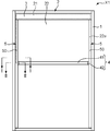
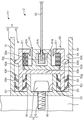
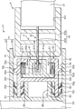
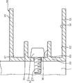
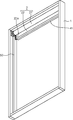
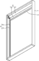
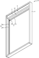
- FIG. 1 It is a schematic plan view which shows the screen apparatus which concerns on this embodiment. It is the II sectional view taken on the line shown in FIG. It is the II-II sectional view taken on the line shown in FIG. It is a schematic sectional drawing which shows progress in the manufacturing process of the screen apparatus which concerns on this embodiment, Comprising: The state which attached the outer side guide rail with respect to the frame member is shown. It is a schematic perspective view which shows progress in the manufacturing process of the screen apparatus which concerns on this embodiment, Comprising: The state which attached the outer side guide rail and the winding screen with respect to the frame member is shown.
- the screen device according to the present invention may include any constituent member that is not shown in each drawing referred to in this specification.
- the screen device X1 is a winding screen device applied to a window frame in a house or the like.
- the screen device X1 includes a frame member 1, a winding screen 2, a front cover 3, a weight bar 4, a pair of guide rails 5, and a plurality of fixing members 7.
- the screen device X1 may have a configuration in which a screen member 22 described later is wound up electrically, or may be configured in which the screen member 22 is manually wound up with a chain or the like.
- the screen device according to the present invention is also applied to systems other than the winding type.
- the screen device according to the present invention is applied not only to a window frame in a house, but also to a projector screen, for example.
- the frame member 1 is a member constituting the outer frame of the screen device X1.
- the frame member 1 has a rectangular shape in plan view.
- the rectangular area surrounded by the frame member 1 is an area opened and closed by a screen member 22 described later.
- the frame member 1 does not have to be rectangular in plan view, and can be appropriately changed according to the usage mode of the screen device X1. Further, the frame member 1 may not be provided. For example, a window frame in a house or the like may be used as the frame member 1.
- the winding screen 2 includes a winding shaft 21 and a screen member 22.
- the winding shaft 21 has a role of winding the screen member 22.
- the winding shaft 21 is a columnar member that extends in the short direction of the frame member 1.
- the winding shaft 21 is disposed along the upper frame of the frame member 1 in a region surrounded by the frame member 1.
- the winding shaft 21 is attached to both side frames of the frame member 1 so as to be rotatable in the circumferential direction of the winding shaft 21.
- the winding shaft 21 may be arranged along the lower frame of the frame member 1.
- the screen member 22 has a role of opening and closing a region surrounded by the frame member 1.
- the upper end portion of the screen member 22 is connected to the winding shaft 21.
- the screen member 22 is wound around the winding shaft 21 according to the rotation of the winding shaft 21, thereby opening a part or all of the region surrounded by the frame member 1. Further, the screen member 22 is sent out from the take-up shaft 21 according to the rotation of the take-up shaft 21, thereby closing part or all of the region surrounded by the frame member 1.
- the screen member 22 has side end portions 22a located at both ends of the screen member 22 in the left-right direction.
- Each side end 22a is a portion that is held by each inner guide rail 60 of each guide rail 5 described later.
- Each side end portion 22a is set to have a larger thickness than portions other than each side end portion 22a.
- Each side end 22a is formed, for example, by attaching a retaining member so as to cover the screen material from both the front and back surfaces with respect to both side ends in the left-right direction of the sheet-like screen material.
- each side edge part 22a may be formed by setting the thickness of the both-sides edge part itself in the left-right direction of a sheet-like screen raw material large compared with the thickness of parts other than the said both-sides edge part, for example. .
- the front cover 3 has a role of preventing the winding shaft 21 from being visually recognized by the user.
- the front cover 3 is arranged in front of the winding shaft 21, that is, on the user side so as to overlap the winding shaft 21 in plan view.
- the front cover 3 is fixed to the frame member 1 using, for example, a magnet sheet (not shown).
- the weight bar 4 has a role of applying an appropriate tension to the screen member 22 in the vertical direction of the screen member 22 in a state where the screen member 22 is fed from the winding shaft 21.
- the weight bar 4 has a main body 41 and a pair of left and right side caps 42.
- the main body 41 extends along the left-right direction of the screen member 22.
- the main body 41 is attached to the lower end of the screen member 22.
- the length of the main body 41 is set slightly shorter than the width of the screen member 22 in the left-right direction.
- Side caps 42 are attached to both ends of the lower end portion of the screen member 22 exposed from the main body portion 41 on both the left and right sides of the main body portion 41. Specifically, as shown in FIG.
- the side cap 42 includes one side member 42a and the other side member 42b.
- the one side member 42 a and the other side member 42 b are fixed by a fixing tool such as a screw (not shown) in a state where the lower end portion of the screen member 22 is sandwiched in the thickness direction of the screen member 22.
- the side cap 42 has a recess 42c between the one side member 42a and the other side member 42b.
- the end of the main body 41 is fitted in the recess 42c.
- the end of the side cap 42 opposite to the recess 42c is fitted in a recess 54 of the outer guide rail 50 described later.
- Each guide rail 5 has a role of guiding the vertical movement of the screen member 22.
- Each guide rail 5 is arranged along the both side frames of the frame member 1 in a region surrounded by the frame member 1.
- Each guide rail 5 includes an outer guide rail 50 and an inner guide rail 60.
- the outer guide rail 50 is a member corresponding to the rail housing member of the screen device according to the present invention.
- the outer guide rail 50 has a role of preventing the inner guide rail 60 from being visually recognized by the user by accommodating the inner guide rail 60.
- the outer guide rail 50 is a concave member extending along the vertical direction of the screen member 22.
- the outer guide rail 50 has a first side wall 51, a second side wall 52, a first bottom wall 53, a recess 54, a first intermediate wall 55, and a second intermediate wall 56.
- the first side wall 51 and the second side wall 52 extend along the left-right direction of the screen member 22 from both ends of the first bottom wall 53 in contact with the side frame of the frame member 1 in the thickness direction of the screen member 22.
- the first side wall 51 and the second side wall 52 face each other in the thickness direction of the screen member 22.
- a space surrounded by the first side wall 51, the second side wall 52, and the first bottom wall 53 is a recess 54.
- the first intermediate wall 55 and the second intermediate wall 56 extend from the first bottom wall 53 into the recess 54 along the left-right direction of the screen member 22.
- the first intermediate wall 55 and the second intermediate wall 56 face each other in the thickness direction of the screen member 22.
- the widths of the first intermediate wall 55 and the second intermediate wall 56 in the left-right direction of the screen member 22 are set to be smaller than the widths of the first side wall 51 and the second side wall 52 in the left-right direction of the screen member 22.
- the first intermediate wall 55 is located on the first side wall 51 side compared to the second intermediate wall 56
- the second intermediate wall 56 is on the second side wall 52 side compared to the first intermediate wall 55. Is located.
- the space between the first side wall 51 and the first intermediate wall 55 is referred to as a first space S1.
- a space between the second side wall 52 and the second intermediate wall 56 is referred to as a second space S2.
- a space between the first intermediate wall 55 and the second intermediate wall 56 is referred to as a third space S3.
- the outer guide rail 50 has a first side wall 51, a second side wall 52, a first bottom wall 53, a recess 54, a first intermediate wall 55, and a second intermediate wall 56.
- any concave member that can accommodate the inner guide rail 60 inside may be used.
- the fixing member 7 is a screwing member having a head portion 71 and a screw portion 72.
- the screw portion 72 extends from the concave portion 54 side to the side frame of the frame member 1 through the first bottom wall 53. Thereby, the screw portion 72 fixes the first bottom wall 53 and the side frame of the frame member 1.
- the head 71 of the fixing member 7 is disposed in the third space S3.
- the plurality of fixing members 7 are arranged at predetermined intervals along the vertical direction of the screen member 22.
- the plurality of fixing members 7 fix the outer guide rail 50 and the frame member 1.
- the number and arrangement of the fixing members 7 are arbitrary, and can be appropriately changed according to the usage mode of the screen device X1.
- the inner guide rail 60 is a member corresponding to the rail member of the screen device according to the present invention.
- the inner guide rail 60 serves to guide the vertical movement of the screen member 22. Similar to the outer guide rail 50, the inner guide rail 60 extends along the vertical direction of the screen member 22.
- the inner guide rail 60 includes a first rail member 61 and a second rail member 62.
- the first rail member 61 is a member that directly guides the vertical movement of the screen member 22.
- the first rail member 61 has a hollow shape.
- the first rail member 61 has a first accommodating portion 61a and a first slit 61b.
- the first accommodating portion 61 a corresponds to the hollow portion of the first rail member 61.
- the first accommodating portion 61 a extends along the vertical direction of the screen member 22.
- the first slit 61 b communicates the first housing portion 61 a and the outside of the first rail member 61.
- the first slit 61 b extends along the vertical direction of the screen member 22.
- the side end 22a of the screen member 22 is accommodated in the first accommodating portion 61a via the first slit 61b. In other words, the screen member 22 is located inside and outside the first housing portion 61a via the first slit 61b.
- the width of the first slit 61 b in the thickness direction of the screen member 22 is smaller than the thickness of the side end portion 22 a of the screen member 22. For this reason, the screen member 22 is restricted by the first rail member 61 from being displaced in the left-right direction. Further, the width of the first accommodating portion 61 a in the thickness direction of the screen member 22 is larger than the thickness of the side end portion 22 a of the screen member 22. For this reason, the screen member 22 is movable in the up-down direction of the screen member 22 in a state where the displacement of the screen member 22 in the left-right direction is restricted.
- the second rail member 62 is a member that holds the first rail member 61.
- the second rail member 62 includes a first opposing wall 62a, a second opposing wall 62b, a second bottom wall 62c, a second accommodating portion 62d, a second slit 62e, a first projecting portion 62f, a second projecting portion 62g, a plurality of It has a first tongue piece 62h, a plurality of second tongue pieces 62i, a first protrusion 62j, and a second protrusion 62k.
- the first opposing wall 62 a is a part facing the first side wall 51.
- the second opposing wall 62 b is a part that faces the second side wall 52.
- the second bottom wall 62 c is a part facing the first bottom wall 53.
- a space surrounded by the first opposing wall 62a, the second opposing wall 62b, and the second bottom wall 62c serves as a second accommodating portion 62d that accommodates the first rail member 61.
- a second slit 62e is provided on the upper wall of the second rail member 62 located on the opposite side of the second bottom wall 62c with the second housing portion 62d interposed therebetween.
- the second accommodating portion 62d communicates with the outside of the second rail member 62 through the second slit 62e.
- the 1st rail member 61 is accommodated in the 2nd accommodating part 62d. Thereby, the surface in which the 1st slit 61b was provided among the 1st rail members 61 is exposed from the 2nd accommodating part 62d in the 2nd slit 62e.
- An elastic body E ⁇ b> 1 is interposed between the inner peripheral surface of the second rail member 62 and the outer peripheral surface of the first rail member 61. Thereby, the space
- the first convex portion 62j extends from the first opposing wall 62a toward the first side wall 51 along the thickness direction of the screen member 22.
- the 2nd convex part 62k is extended in the 2nd side wall 52 side along the thickness direction of a screen member from the 2nd opposing wall 62b.
- the separation distance from the vertex of the first convex portion 62j to the vertex of the second convex portion 62k in the thickness direction of the screen member 22 is set to be substantially the same as the width of the concave portion 54 of the outer guide rail 50 in the thickness direction. ing.
- the second rail member 62 is accommodated in the concave portion 54 at a position where the first convex portion 62j contacts the first side wall 51 and the second convex portion 62k contacts the second side wall 52. This prevents the inner guide rail 60 from rattling in the recess 54.
- the first protrusion 62f extends from the end of the second bottom wall 62c on the first opposing wall 62a side to the first bottom wall 53 side along the left-right direction of the screen member 22.
- the first protrusion 62f is inserted into the first space S1.
- the second protrusion 62g extends from the end of the second bottom wall 62c on the second opposing wall 62b side to the first bottom wall 53 side along the left-right direction of the screen member 22.
- the second protrusion 62g is inserted into the second space S2.
- the inner guide rail 60 is completely accommodated in the recess 54 of the outer guide rail 50 at the insertion position where the first protrusion 62f is inserted into the first space S1 and the second protrusion 62g is inserted into the second space S2. Has been. Thereby, the inner guide rail 60 is in a state where it is not visually recognized by the user in the thickness direction of the screen member 22.
- the insertion position in the present embodiment is the contact position between the tip of the first projection 62f and the tip of the second projection 62g and the first bottom wall 53, or the tip of the first intermediate wall 55 and the second middle. The contact position of the front-end
- positioning and the number of the 1st projection parts 62f and the 2nd projection parts 62g are arbitrary, and can be suitably changed according to the usage condition of the screen apparatus X1.
- a single protrusion that extends from the center of the second bottom wall 62c in the thickness direction of the screen member 22 toward the first bottom wall 53 is provided. It is good also as a structure which inserts a projection part in 3rd space S3.
- the head 71 of the fixing member 7 may be disposed so as to avoid the protrusion in the third space S3, or may be disposed in the first space S1 or the second space S2.
- Each first tongue piece 62h extends from the first protrusion 62f along the protrusion direction of the first protrusion 62f, that is, the direction intersecting the left-right direction of the screen member 22. Specifically, some of the first tongue pieces 62h of the first tongue pieces 62h extend from the first protrusion 62f to the first side wall 51 side. The remaining first tongue piece 62h of the first tongue pieces 62h extends from the first protrusion 62f to the first intermediate wall 55 side. And each 1st tongue piece 62h is between the 1st projection part 62f and the 1st side wall 51, and between the 1st projection part 62f and the 1st intermediate wall 55 in the insertion position of the 1st projection part 62f.
- each first tongue piece 62 h is pressed against the first side wall 51 and the first intermediate wall 55.
- Each second tongue piece 62i extends from the second projecting portion 62g along the projecting direction of the second projecting portion 62g, that is, the direction intersecting the left-right direction of the screen member 22. Specifically, some second tongue pieces 62i out of the second tongue pieces 62i extend from the second protrusions 62g to the second side wall 52 side. The remaining second tongue piece 62i of the second tongue pieces 62i extends from the second protrusion 62g toward the second intermediate wall 56 side.
- each 2nd tongue piece 62i is between the 2nd projection part 62g and the 2nd side wall 52, and between the 2nd projection part 62g and the 2nd intermediate wall 56 in the said insertion position of the 2nd projection part 62g. It is elastically deformed. Accordingly, each second tongue piece 62 i is pressed against the second side wall 52 and the second intermediate wall 56.
- the first tongue pieces 62h and the second tongue pieces 62i are arranged in the outer guide rail 50 in the thickness direction of the screen member 22 at the insertion positions of the first protrusions 62f and the second protrusions 62g. It is in pressure contact with the peripheral surface. For this reason, the inner guide rail 60 is held by the outer guide rail 50 without any fixing work such as screwing. As a result, the inner guide rail 60 is in a state where it can be detached from the recess 54 of the outer guide rail 50 in the left-right direction of the screen member 22.
- first tongue pieces 62h of the first tongue pieces 62h extend from the first protrusions 62f toward the first side wall 51, and the remaining portions of the first tongue pieces 62h.
- the first tongue piece 62h extends from the first protrusion 62f toward the first intermediate wall 55, but is not limited thereto.
- each first tongue piece 62h may extend only from the first protrusion 62f toward the first side wall 51.
- a part of the second tongue pieces 62i of the second tongue pieces 62i extends from the second protrusion 62g toward the second side wall 52, and the remaining portion of the second tongue pieces 62i.
- each second tongue piece 62i may extend only from the second protrusion 62g to the second side wall 52 side.
- the inner guide rail 60 is constituted by two members, the first rail member 61 and the second rail member 62, but is not limited thereto.
- the inner guide rail 60 may be configured only by the second rail member 62, and the side end portion 22a of the screen member 22 may be accommodated directly in the second accommodation portion 62d.
- the thickness of the side end portion 22 a of the screen member 22 is set to be larger than the width of the second slit 62 e in the thickness direction of the screen member 22.
- the inner guide rail 60 may include a third rail member in addition to the first rail member 61 and the second rail member 62.
- the third rail member is accommodated in the first accommodating portion 61a and has a third accommodating portion and a third slit, and the side end portion of the screen member 22 is passed through the third slit to the third accommodating portion. 22a is accommodated.
- the thickness of the side end portion 22 a of the screen member 22 is set larger than the width of the third slit in the thickness direction of the screen member 22.
- the outer guide rail 50 holds the inner guide rail 60 so that the inner guide rail 60 can be attached to and detached from the recess 54 in the left-right direction of the screen member 22. For this reason, the maintainability of the screen member 22 is improved.
- the screen member is removed from the screen device as follows. It is necessary to desorb. First, the outer guide rail is removed from the side frame of the frame member.
- the engaging body between the screen member and the inner guide rail is detached from the outer guide rail.
- the inner guide rail 60 can be detached from the concave portion 54 of the outer guide rail 50 in the left-right direction of the screen member 22.
- the inner guide rail 60 can be removed from the concave portion 54 of the outer guide rail 50 without removing the outer guide rail 50 from the frame member 1.
- a troublesome process of removing the inner guide rail 60 from the concave portion 54 of the outer guide rail 50 along the vertical direction of the screen member 22 is unnecessary. Therefore, the engaging body of the screen member 22 and the inner guide rail 60 can be easily separated from the outer guide rail 50, thereby improving the maintainability of the screen member 22.
- the first tongue pieces 62h and the second tongue pieces 62i are elastically deformed in the first space S1 and the second space S2.
- the first tongue pieces 62 h and the second tongue pieces 62 i are pressed against the inner peripheral surface of the outer guide rail 50.
- the first protrusion 62f and the second protrusion 62g are held on the inner peripheral surface of the outer guide rail 50. For this reason, it can suppress that the 1st projection part 62f and the 2nd projection part 62g slip out carelessly from 1st space S1 and 2nd space S2, and can hold the inner side guide rail 60 on the outer side guide rail 50 appropriately. it can.
- the head 71 of the fixing member 7 is disposed in the third space S3.
- the third space S3 which is a dead space between the first intermediate wall 55 and the second intermediate wall 56 in the recess 54, is effectively utilized, and the outer guide rail 50 and the frame member 1 are fixed by the fixing member 7.
- the side frame can be fixed.
- the screen device X1 described above can be manufactured reasonably and easily, for example, by a method including the following steps.
- the construction method of the screen device X1 will be described in detail with reference to FIGS.
- a frame member 1 made of wood, metal material, resin material or the like is prepared.
- the frame member 1 is formed in a substantially rectangular shape in plan view.
- the winding screen 2 including the winding shaft 21 and the screen member 22 and the main body portion 41 of the weight bar 4 are prepared, and the winding in a state where the main body portion 41 is attached to the lower end portion of the screen member 22.
- a take screen 2 is attached to the frame member 1.
- the screen material such as cloth is formed in a substantially rectangular shape having an area comparable to the area surrounded by the frame member 1.
- the securing member which consists of resin materials etc. is attached to the both ends of the said screen raw material, ie, both long sides of a screen raw material.
- the tape-shaped retaining member is bent, and the retaining member is bonded to the both side ends so as to sandwich both side ends of the screen material from both sides of the screen material.
- the screen member 22 is formed.
- the upper end part of the screen member 22, ie, one short side of the screen member 22, is attached along the axial direction of the said winding shaft 21 with respect to the winding shaft 21 formed in the column shape.
- the screen member 22 can be wound around the winding shaft 21 in the circumferential direction of the winding shaft 21.
- the main body 41 is attached to the lower end of the screen member 22. Specifically, the main body 41 is attached along the short side of the screen member 22 that is located on the opposite side of the short side attached to the winding shaft 21.
- the length of the main body portion 41 is set smaller than the width of the lower end portion of the screen member 22, and both ends of the lower end portion from the main body portion 41 on both sides in the length direction of the main body portion 41 are set. Exposed.
- the winding screen 2 with the main body 41 attached in this way is arranged along the upper frame of the frame member 1 in the region surrounded by the frame member 1. And the winding shaft 21 in the winding screen 2 is fixed to the both side frames of the frame member 1 in a state in which the winding shaft 21 is rotatable in the circumferential direction of the winding shaft 21.
- an outer guide rail 50 made of a metal material or a resin material is prepared, and the outer guide rail 50 is attached to the frame member 1. Specifically, for example, by performing extrusion molding along one direction, the outer guide rail 50 having a concave shape extending along the one direction is formed.
- the outer guide rail 50 is fixed to the side frame of the frame member 1 via the fixing member 7.
- the screw portion 72 of the fixing member 7 extends from the recess 54 through the first bottom wall 53 to the side frame of the frame member 1, and the head 71 of the fixing member 7 is connected to the first intermediate wall 55 and the second intermediate wall. It arrange
- the inner guide rail 60 including the first rail member 61 and the second rail member 62 is prepared.
- a hollow first rail member 61 extending along one direction is formed by extruding a resin material.
- the hollow second rail member 62 extending in one direction is formed by extruding the resin material.
- the first tongue piece 62h and the second tongue piece 62i of the second rail member 62 have a lower elastic modulus than that of the portion other than the first tongue piece 62h and the second tongue piece 62i, for example, by coextrusion molding. Formed to be.
- the first rail member 61 is inserted into the second housing portion 62 d of the second rail member 62 along the length direction of the second rail member 62. Accordingly, the first rail member 61 is held in the second housing portion 62d with the first slit 61b exposed from the second slit 62e.
- the side end portion 22a of the screen member 22 is accommodated in the first accommodating portion 61a through the first slit 61b. Thereby, the displacement in the short side direction of the screen member 22, ie, the left-right direction of the screen member 22, is controlled.
- the inner guide rail 60 is accommodated in the recess 54 of the outer guide rail 50 along the left-right direction of the screen member 22.
- the first protrusion 62f is inserted into the first space S1 between the first side wall 51 and the first intermediate wall 55
- the second protrusion 62g is connected to the second side wall 52 and the second intermediate wall 56. Is inserted into the second space S2.
- the insertion is stopped at a position where the tip of the first intermediate wall 55 and the tip of the second intermediate wall 56 are in contact with the second bottom wall 62c.
- the inner guide rail 60 is completely accommodated in the concave portion 54 of the outer guide rail 50 at the insertion position where the insertion is stopped.
- first tongue piece 62 h and the second tongue piece 62 i are elastically deformed in the thickness direction of the screen member 22, a repulsive force due to the elastic deformation is applied to the inner peripheral surface of the outer guide rail 50. Thereby, the inner guide rail 60 is held by the outer guide rail 50.
- a front cover 3 made of a metal material or the like is prepared, and the front cover 3 is attached to the frame member 1.
- the front cover 3 is formed with a size that prevents the winding screen 2 from being visually recognized by the user in a state where the screen member 22 is completely wound around the winding shaft 21.
- the front cover 3 is disposed in front of the winding shaft 21 and is fixed to the frame member 1 via a magnet sheet (not shown).
- the side cap 42 of the weight bar 4 is prepared, and the side cap 42 is attached to the lower end of the screen member 22 exposed from the main body 41 on both sides in the length direction of the main body 41.
- a pair of one side member 42a and the other side member 42b constituting the side cap 42 are prepared.
- the one-side member 42a and the other-side member 42b are arranged so as to face each other across the portion exposed from the main body portion 41 in the lower end portion of the screen member 22.
- the end of the main body 41 is disposed in the recess 42c, which is a space between the one side member 42a and the other side member 42b, and a part of the side cap 42 is disposed in the recess 54 of the outer guide rail 50.
- the one side member 42a and the other side member 42b are fixed by screws or the like. Thereby, the vertical movement of the weight bar 4 is guided by the outer guide rail 50.
- the main body 41 may be attached to the lower end portion of the screen member 22 together with the side cap 42 in this step.
- the inner guide rail 60 can be held by the outer guide rail 50 without separately providing a fixture, and therefore the inner guide rail 60 is moved in the left-right direction of the screen member 22. It can be made removable from the recessed part 54 of this. Thereby, the maintainability of the screen apparatus X1 can be improved.
- the side cap 42 is attached to a portion of the lower end portion of the screen member 22 exposed from the main body portion 41. For this reason, when removing the inner guide rail 60 from the recess 54 of the outer guide rail 50 in the left-right direction of the screen member 22, first, the side cap 42 is removed by separating the one side member 42a and the other side member 42b.
- the inner guide rail 60 can be easily removed from the recess 54 without any problem.
- the procedure for removing the inner guide rail 60 from the recess 54 of the outer guide rail 50 is not limited to the above procedure.
- the inner guide rail 60 may be removed from the concave portion 54 after the main body 41 is also removed from the screen member 22 in addition to the side cap 42, or the main body 41 and the side cap 42 are attached to the screen member 22.
- the inner guide rail 60 may be removed from the recess 54.
- the screen apparatus X1 can be manufactured by a simple process.
- the screen device X1 according to the present embodiment can be variously modified as follows.
- the first tongue pieces 62h and the second tongue pieces are associated with the insertion of the first protrusions 62f and the second protrusions 62g into the first space S1 and the second space S2.
- the inner guide rail 60 is held by the outer guide rail 50 due to the elastic deformation of 62i, but is not limited thereto.
- the inner guide rail 60 may be held by the outer guide rail 50 by any method within a range not departing from the gist of the present invention.
- the first tongue pieces 62h and the second tongue pieces 62i do not exist, and the first protrusions 62f and the second protrusions into the first space S1 and the second space S2.
- a configuration in which the inner guide rail 60 is held by the outer guide rail 50 only by inserting the portion 62g may be employed.
- each first tongue piece 62h is first from the first opposing wall 62a.
- a configuration may be employed in which each second tongue piece 62i extends from the second opposing wall 62b to the second side wall 52 side while extending to the side wall 51 side.
- a repulsive force of the elastic deformation is applied to the first side wall 51 by elastically deforming each first tongue piece 62h between the first side wall 51 and the first opposing wall 62a.
- the second side wall 52 is subjected to elastic repulsion force by elastically deforming each second tongue piece 62i between the second side wall 52 and the second opposing wall 62b.
- the inner guide rail 60 is held by the outer guide rail 50.
- the first protrusion 62f and the second protrusion 62g extending along the left-right direction of the screen member 22 do not exist.
- variety of the outer side guide rail 50 and the inner side guide rail 60 in the left-right direction of the screen member 22 can be made small compared with the screen apparatus X1 which concerns on this embodiment.
- the screen device extends along the vertical direction of the screen member and the screen member so that the screen member can move in the vertical direction while restricting the displacement of the screen member in the horizontal direction.
- the rail housing member holds the rail member so that the rail member can be detached from the recess in the left-right direction of the screen member. Can be easily removed from the recess of the rail housing member. For this reason, for example, in a state where the rail housing member is attached to a frame member for fixing the rail housing member along the window frame or the like, the rail member can be removed from the recess of the rail housing member. A troublesome process of drawing the member from the recess of the rail housing member along the vertical direction of the screen member becomes unnecessary. Therefore, the engaging body of the screen member and the rail member can be easily separated from the rail housing member, and the maintainability of the screen member is improved.
- the rail member extends along the up-and-down direction of the screen member and accommodates the side end portion of the screen member, and extends along the up-and-down direction and communicates the inside and outside of the containing portion.
- the width of the slit is smaller than the thickness of the side end portion of the screen member, and the rail member is accommodated in the accommodating portion by the side end portion of the screen member through the slit. By doing so, it is preferable to restrict the displacement of the screen member in the left-right direction.
- the width of the slit to be smaller than the thickness of the side end portion of the screen member, the side end portion can be prevented from slipping out of the rail member through the slit. For this reason, the displacement in the left-right direction of a screen member is controlled, and it can suppress that a screen member and a rail member isolate
- the rail housing member includes a first side wall and a second side wall located on both sides in the thickness direction of the screen member across the concave portion, a first bottom wall connecting the first side wall and the second side wall, A first intermediate wall extending from the first bottom wall to the recess, and a second intermediate wall extending from the first bottom wall to the recess and positioned closer to the second side wall than the first intermediate wall.
- the rail member includes a second bottom wall facing the first bottom wall, a first protrusion extending from the second bottom wall toward the first bottom wall, and the first protrusion from the first protrusion.
- a second tongue piece extending in a direction intersecting with the second protrusion from the portion, and the first protrusion Is inserted into the space between the first side wall and the first intermediate wall, so that the first tongue piece is located between the first protrusion and the first side wall in the thickness direction of the screen member or
- the first protrusion and the first intermediate wall are elastically deformed, and the second protrusion is inserted into the space between the second side wall and the second intermediate wall.
- Two tongue pieces are elastically deformed between the second projecting portion and the second side wall or between the second projecting portion and the second intermediate wall in the thickness direction, whereby the rail housing member is moved to the rail. It is preferable to hold the member.
- the first protrusion is inserted into the space between the first side wall and the first intermediate wall.
- the second protrusion is inserted into the space between the second side wall and the second intermediate wall. Accordingly, the first tongue piece and the second tongue piece are elastically deformed in the thickness direction of the screen member, and the repulsive force of the elastic deformation is at least of the first side wall, the first intermediate wall, the second side wall, and the second intermediate wall. Join one.
- the first tongue and the second tongue cause the first protrusion and the second protrusion to be a space between the first side wall and the first intermediate wall and a space between the second side wall and the second intermediate wall. Can be prevented from inadvertently exiting. Therefore, the rail member can be appropriately held by the rail housing member.
- the rail housing member has a first side wall and a second side wall located on both sides in the thickness direction of the screen member with the recess interposed therebetween, and the rail member has a first facing facing the first side wall.
- the rail housing member may hold the rail member.
- the rail member extends from the first opposing wall of the rail member toward the first side wall of the rail housing member, and the second side wall of the rail housing member extends from the second opposing wall of the rail member.
- a second tongue extending to the side.
Landscapes
- Engineering & Computer Science (AREA)
- Structural Engineering (AREA)
- Architecture (AREA)
- Civil Engineering (AREA)
- Physics & Mathematics (AREA)
- General Physics & Mathematics (AREA)
- Operating, Guiding And Securing Of Roll- Type Closing Members (AREA)
- Overhead Projectors And Projection Screens (AREA)
Priority Applications (2)
| Application Number | Priority Date | Filing Date | Title |
|---|---|---|---|
| EP15786375.4A EP3130742B1 (en) | 2014-04-30 | 2015-04-03 | Screen device |
| US15/307,280 US9982483B2 (en) | 2014-04-30 | 2015-04-03 | Screen device |
Applications Claiming Priority (2)
| Application Number | Priority Date | Filing Date | Title |
|---|---|---|---|
| JP2014-093573 | 2014-04-30 | ||
| JP2014093573A JP6228506B2 (ja) | 2014-04-30 | 2014-04-30 | スクリーン装置 |
Publications (1)
| Publication Number | Publication Date |
|---|---|
| WO2015166765A1 true WO2015166765A1 (ja) | 2015-11-05 |
Family
ID=54358502
Family Applications (1)
| Application Number | Title | Priority Date | Filing Date |
|---|---|---|---|
| PCT/JP2015/060592 Ceased WO2015166765A1 (ja) | 2014-04-30 | 2015-04-03 | スクリーン装置 |
Country Status (4)
| Country | Link |
|---|---|
| US (1) | US9982483B2 (enExample) |
| EP (1) | EP3130742B1 (enExample) |
| JP (1) | JP6228506B2 (enExample) |
| WO (1) | WO2015166765A1 (enExample) |
Families Citing this family (17)
| Publication number | Priority date | Publication date | Assignee | Title |
|---|---|---|---|---|
| CN107533281A (zh) * | 2015-03-09 | 2018-01-02 | 文塔纳3D有限责任公司 | 用于佩珀尔幽灵幻像的膜张紧系统 |
| EP3098376A1 (en) * | 2015-05-29 | 2016-11-30 | Plastex SA | Upright for a shading system, removable flange of the upright and corresponding coupling means |
| KR102527214B1 (ko) * | 2016-05-04 | 2023-04-28 | 삼성디스플레이 주식회사 | 롤러블 표시 장치 |
| US10538962B2 (en) * | 2016-06-16 | 2020-01-21 | Hall Labs Llc | Easy installation headrail assembly |
| US11421474B2 (en) | 2016-08-03 | 2022-08-23 | Defender Screens International, Llc | Self-tensioning magnetic tracks and track assemblies |
| US9719292B1 (en) | 2016-08-03 | 2017-08-01 | Defender Screens International LLC | Self-tensioning magnetic tracks and track assemblies |
| US10253563B2 (en) | 2017-01-03 | 2019-04-09 | Mechoshade Systems, Llc | Base channel coupling |
| US10260280B2 (en) | 2017-01-03 | 2019-04-16 | Mechoshade Systems, Llc | Systems and methods for roller blind channel coupling |
| US10662705B2 (en) * | 2017-04-14 | 2020-05-26 | Hall Labs Llc | Track system for retractable wall |
| US20190048658A1 (en) * | 2017-08-09 | 2019-02-14 | Professional Blinds System Inc. | Construction assembly for installing a roller blind or the like |
| EP3947889B1 (en) * | 2019-04-03 | 2024-12-25 | Michael Heissenberg | Retractable screen with tensioning track |
| US11840883B2 (en) * | 2019-09-13 | 2023-12-12 | Inpro Corporation | Shade system with breakable end tips |
| WO2021080051A1 (ko) * | 2019-10-25 | 2021-04-29 | 엘지전자 주식회사 | 디스플레이 디바이스 |
| KR102710186B1 (ko) * | 2019-12-27 | 2024-09-25 | 엘지전자 주식회사 | 처짐 방지 구조를 갖는 디스플레이 디바이스 |
| CN115379781A (zh) | 2020-02-24 | 2022-11-22 | 防守者屏幕国际有限公司 | 可伸缩屏风系统 |
| DE202020103347U1 (de) * | 2020-06-10 | 2020-06-18 | Alukon Kg | Führungseinsatz für eine Führungsschiene eines Behangsystems; Führungsschiene für ein Behangsystem und Behangsystem zum Führen eines Behangs |
| CN119301341A (zh) * | 2022-05-02 | 2025-01-10 | 防守者屏幕国际有限公司 | 可伸缩遮帘系统 |
Citations (3)
| Publication number | Priority date | Publication date | Assignee | Title |
|---|---|---|---|---|
| JPH11141250A (ja) * | 1997-09-04 | 1999-05-25 | Morito Co Ltd | ロールスクリーン装置 |
| JP2004211298A (ja) * | 2002-12-26 | 2004-07-29 | Tachikawa Blind Mfg Co Ltd | ロールブラインドのスクリーン案内装置 |
| JP2012172505A (ja) * | 2011-02-24 | 2012-09-10 | Seiki Hanbai Co Ltd | 建物開口部用スクリーン装置 |
Family Cites Families (13)
| Publication number | Priority date | Publication date | Assignee | Title |
|---|---|---|---|---|
| US3220469A (en) * | 1963-08-28 | 1965-11-30 | Robert G Oehmig | Screen frame |
| US4233790A (en) * | 1979-01-08 | 1980-11-18 | Donel Corporation | Extrusions and building structures |
| JPH0629440Y2 (ja) | 1986-02-07 | 1994-08-10 | セイキ販売株式会社 | 巻取式スクリーン装置 |
| US7699091B2 (en) * | 2003-08-11 | 2010-04-20 | Steel Stitch Corporation | Awning system with snap-on functional components |
| JP3881665B2 (ja) * | 2004-03-24 | 2007-02-14 | 東海興業株式会社 | パッキン及びその装着方法 |
| DE502007003134D1 (de) * | 2007-01-31 | 2010-04-29 | Arvinmeritor Gmbh | Führungssystem für ein Rollo eines Schiebedachsystems |
| ITPS20070039A1 (it) * | 2007-12-07 | 2009-06-08 | Garattoni Dario Di R I | Sistema per l'installazione verticale o orizzontale di rete/tessuto/crystal con zip saldata o cucita |
| AU2010100720B4 (en) * | 2009-10-29 | 2011-09-08 | Acmeda Pty Ltd | A blind system |
| SE1051081A1 (sv) * | 2010-10-15 | 2011-11-08 | Erco Systems Ab | Styrskena för rullgardin |
| TW201241296A (en) * | 2011-04-06 | 2012-10-16 | Komatsu Denki Sangyo Kabushiki Kaisha | Sheet shutter |
| JP5849450B2 (ja) * | 2011-06-15 | 2016-01-27 | アイシン精機株式会社 | サンシェード装置 |
| GB2502039B (en) * | 2012-02-29 | 2017-11-15 | Ideas By Design Ltd | Apparatus for mounting a screen guide rail |
| JP6228504B2 (ja) | 2014-04-11 | 2017-11-08 | フクビ化学工業株式会社 | スクリーン装置およびその製造方法 |
-
2014
- 2014-04-30 JP JP2014093573A patent/JP6228506B2/ja active Active
-
2015
- 2015-04-03 WO PCT/JP2015/060592 patent/WO2015166765A1/ja not_active Ceased
- 2015-04-03 US US15/307,280 patent/US9982483B2/en active Active
- 2015-04-03 EP EP15786375.4A patent/EP3130742B1/en active Active
Patent Citations (3)
| Publication number | Priority date | Publication date | Assignee | Title |
|---|---|---|---|---|
| JPH11141250A (ja) * | 1997-09-04 | 1999-05-25 | Morito Co Ltd | ロールスクリーン装置 |
| JP2004211298A (ja) * | 2002-12-26 | 2004-07-29 | Tachikawa Blind Mfg Co Ltd | ロールブラインドのスクリーン案内装置 |
| JP2012172505A (ja) * | 2011-02-24 | 2012-09-10 | Seiki Hanbai Co Ltd | 建物開口部用スクリーン装置 |
Non-Patent Citations (1)
| Title |
|---|
| See also references of EP3130742A4 * |
Also Published As
| Publication number | Publication date |
|---|---|
| JP6228506B2 (ja) | 2017-11-08 |
| EP3130742A1 (en) | 2017-02-15 |
| US9982483B2 (en) | 2018-05-29 |
| EP3130742A4 (en) | 2018-02-28 |
| JP2015209731A (ja) | 2015-11-24 |
| US20170044826A1 (en) | 2017-02-16 |
| EP3130742B1 (en) | 2022-09-28 |
Similar Documents
| Publication | Publication Date | Title |
|---|---|---|
| JP6228506B2 (ja) | スクリーン装置 | |
| JP6228504B2 (ja) | スクリーン装置およびその製造方法 | |
| US9682577B2 (en) | Paper storage, printer and method for using multiple types of mediums | |
| WO2013009460A4 (en) | Hand tool and method for cutting plastic fiber optic cable without error | |
| JP2009043728A (ja) | バックライトユニットを有する表示装置 | |
| CN108474401B (zh) | 穿壁安装装置 | |
| KR101226087B1 (ko) | 창문이탈방지구 | |
| JP6574348B2 (ja) | スクリーン装置 | |
| US9309079B1 (en) | Bottom taping tape roll replacement | |
| KR101988061B1 (ko) | 차량용 도어 커튼 어셈블리 | |
| EP3409873A1 (en) | Tension cord mounting for an architectural covering | |
| JP5056994B2 (ja) | 組付状態解除阻止機構 | |
| JP2016020600A (ja) | スクリーン装置 | |
| KR102051893B1 (ko) | 블라인드 고정용 브라켓 및 그를 포함하는 블라인드 장치 | |
| JP4761891B2 (ja) | 内視鏡の湾曲操作装置 | |
| JP2017014885A (ja) | スクリーン装置 | |
| JP6647087B2 (ja) | 引戸装置 | |
| KR101001908B1 (ko) | 개선된 문의 안전장치 | |
| JP6570318B2 (ja) | 基板ユニットのロック構造 | |
| KR200475836Y1 (ko) | 창문고정장치 | |
| US7543624B2 (en) | Curtain hook apparatus and method | |
| JP4486590B2 (ja) | ロール紙の支持構造 | |
| KR101434304B1 (ko) | 롤 스크린용 손잡이 조립체 | |
| JP2009035967A (ja) | シャッタの耐負圧補強具 | |
| JP2009210930A (ja) | 光ファイバテープ及びその単心分離工具 |
Legal Events
| Date | Code | Title | Description |
|---|---|---|---|
| WWE | Wipo information: entry into national phase |
Ref document number: 15307280 Country of ref document: US |
|
| NENP | Non-entry into the national phase |
Ref country code: DE |
|
| 121 | Ep: the epo has been informed by wipo that ep was designated in this application |
Ref document number: 15786375 Country of ref document: EP Kind code of ref document: A1 |
|
| REEP | Request for entry into the european phase |
Ref document number: 2015786375 Country of ref document: EP |
|
| WWE | Wipo information: entry into national phase |
Ref document number: 2015786375 Country of ref document: EP |