WO2015166548A1 - 視覚検査装置及び視覚検査プログラム - Google Patents
視覚検査装置及び視覚検査プログラム Download PDFInfo
- Publication number
- WO2015166548A1 WO2015166548A1 PCT/JP2014/061934 JP2014061934W WO2015166548A1 WO 2015166548 A1 WO2015166548 A1 WO 2015166548A1 JP 2014061934 W JP2014061934 W JP 2014061934W WO 2015166548 A1 WO2015166548 A1 WO 2015166548A1
- Authority
- WO
- WIPO (PCT)
- Prior art keywords
- eye
- target
- presented
- visual inspection
- light
- Prior art date
Links
Images


Classifications
-
- A—HUMAN NECESSITIES
- A61—MEDICAL OR VETERINARY SCIENCE; HYGIENE
- A61B—DIAGNOSIS; SURGERY; IDENTIFICATION
- A61B3/00—Apparatus for testing the eyes; Instruments for examining the eyes
- A61B3/02—Subjective types, i.e. testing apparatus requiring the active assistance of the patient
- A61B3/024—Subjective types, i.e. testing apparatus requiring the active assistance of the patient for determining the visual field, e.g. perimeter types
-
- A—HUMAN NECESSITIES
- A61—MEDICAL OR VETERINARY SCIENCE; HYGIENE
- A61B—DIAGNOSIS; SURGERY; IDENTIFICATION
- A61B3/00—Apparatus for testing the eyes; Instruments for examining the eyes
- A61B3/0016—Operational features thereof
- A61B3/0041—Operational features thereof characterised by display arrangements
- A61B3/005—Constructional features of the display
-
- A—HUMAN NECESSITIES
- A61—MEDICAL OR VETERINARY SCIENCE; HYGIENE
- A61B—DIAGNOSIS; SURGERY; IDENTIFICATION
- A61B3/00—Apparatus for testing the eyes; Instruments for examining the eyes
- A61B3/02—Subjective types, i.e. testing apparatus requiring the active assistance of the patient
- A61B3/028—Subjective types, i.e. testing apparatus requiring the active assistance of the patient for testing visual acuity; for determination of refraction, e.g. phoropters
- A61B3/032—Devices for presenting test symbols or characters, e.g. test chart projectors
-
- A—HUMAN NECESSITIES
- A61—MEDICAL OR VETERINARY SCIENCE; HYGIENE
- A61B—DIAGNOSIS; SURGERY; IDENTIFICATION
- A61B3/00—Apparatus for testing the eyes; Instruments for examining the eyes
- A61B3/02—Subjective types, i.e. testing apparatus requiring the active assistance of the patient
- A61B3/08—Subjective types, i.e. testing apparatus requiring the active assistance of the patient for testing binocular or stereoscopic vision, e.g. strabismus
Definitions
- the present invention relates to a visual inspection apparatus and a visual inspection program.
- Visual field abnormalities are difficult for patients themselves to realize. Therefore, there are visual inspection instruments represented by visual field inspection. Various types of visual inspection instruments are known.
- Humphrey perimeter which is a general perimeter.
- a visual target is displayed on a dome-shaped screen, and the visual field is inspected by whether or not the subject visually recognizes the visual target.
- the eye opposite to the eye under examination is shielded by an eye patch or the like.
- Patent Document 1 if the eye opposite to the eye under examination is in the dark state during visual inspection, the dark adaptation of the opposite eye proceeds, and the opposite eye becomes brighter. It is described that it takes time to get used to (accommodate lightly) and affects the test results.
- HMD head mounted display
- Patent Document 2 a head mounted display
- One of the tasks is that a learning effect occurs on the subject.
- the learning effect is good if the subject learns the pattern or timing at which the visual target is displayed as a result of the visual inspection performed by the subject with the left eye, and the visual inspection is performed with the right eye. A result that does not reflect the actual symptoms of the subject.
- Another problem is that fatigue accumulates in one eye.
- the time required for visual inspection is about 4 minutes per eye.
- the subject must keep gazing at the target with one eye for 4 minutes. And then you have to keep gazing at the optotype for 4 minutes with the other eye.
- a subject performs a visual inspection first from the left eye even if he / she can maintain his / her concentration during the left eye inspection, he / she lacks concentration during the subsequent right eye inspection. There is a risk that. Then, there is a possibility that an accurate result cannot be obtained in the visual inspection of the right eye.
- the main object of the present invention is to provide a visual inspection apparatus and a visual inspection program that can obtain accurate inspection results while reducing the accumulation of fatigue on one eye of a subject.
- the present inventor has studied a technique for solving the above problems all at once.
- the eye undergoing visual inspection is naturally presented with background light along with the visual target.
- the present inventor has conceived a method of presenting light for suppressing dark adaptation to the other eye that has not been visually inspected.
- the present inventor considered that the situation in which light was presented to both eyes as a result could be used for solving the above-mentioned problems.
- the present invention shows that the situation where light is presented to both eyes is a situation where both eyes are brightly adapted and ready for visual inspection in both eyes. Thought. And it is an epoch-making that the target is presented to the other eye before the visual inspection for one eye is completed, instead of examining only one eye using the situation. The present inventor has come up with such knowledge.
- One aspect of the present invention is: A dark adaptation suppression light presentation unit that presents light for suppressing dark adaptation to both eyes of the subject; An optotype presenting unit that presents the optotype to the subject's eye so that the optotype is also presented to the other eye before the visual inspection for one eye is completed; It is a visual inspection apparatus having
- FIG. 6 is a top schematic view of another embodiment of a visual inspection apparatus using a polarizer and a polarizing beam splitter.
- FIG. 6 is a schematic top view of another embodiment of a visual inspection apparatus using a polarizer and a screen. It is the upper surface schematic diagram of the visual inspection apparatus of another embodiment using an active shutter and a time division display apparatus.
- FIG. 6 is a top schematic view of another embodiment of a visual inspection apparatus using an active shutter and a screen.
- Visual inspection device A) HMD section a. Image display (dark adaptation suppression light presentation part & target presentation part) b. Others (optical system, etc.) B) Control computer section 2. Relationship between HMD unit and control computer unit 3. How to use the visual inspection device 4. Visual inspection program and recording medium Effects of the embodiment 6. Modifications etc.
- HMD section a. Image display (dark adaptation suppression light presentation part & target presentation part)
- Others optical system, etc.
- Control computer section 2. Relationship between HMD unit and control computer unit 3. How to use the visual inspection device 4.
- Visual inspection program and recording medium Effects of the embodiment 6. Modifications etc.
- Patent Document 1 Japanese Patent Laid-Open No. 9-47430
- Japanese Patent Laid-Open No. 7-67833 may be adopted as appropriate.
- FIG. 1 is a schematic diagram of a visual inspection apparatus according to this embodiment.
- the visual inspection apparatus according to the present embodiment is roughly configured to include a head mounted display (HMD) unit 10 and a control computer unit 30 as shown in FIG.
- the HMD unit 10 includes a dark adaptation suppression light presentation unit and a visual target presentation unit.
- the dark adaptation suppression light presentation unit and the visual target presentation unit are provided on the image display display 13. The case where it is put together is described.
- the left eye is L and the right eye is R. It should be noted, however, that symbols used in the description of the configuration such as “Each eye”, “Left and right eyes (both eyes)”, or “Left eye configuration” are omitted from the reference numerals. Further, for the configuration for the left eye, L is added after the reference numeral, and for the configuration for the right eye, R is added after the reference numeral.
- subject L and R points out the structure which is not specifically used for each eye, or points out the thing which put together the structure for left eyes, and the structure for right eyes.
- the HMD unit 10 includes a housing 11 and a mounting band 12 connected to the housing 11, so that the HMD unit 10 is mounted on the head of a subject to be visually inspected (hereinafter simply referred to as “subject”). It is configured to be possible.
- the housing 11 incorporates a dark adaptation suppression light presenting unit and a visual target presenting unit.
- the image display displays (13L, 13R) provided for the left and right eyes serve both as a dark adaptation suppression light presentation unit and a target presentation unit.
- 13L is an image display display for the left eye
- 13R is an image display display for the right eye
- (13L, 13R) are collectively referred to as “image display display 13”.
- FIG. 2 is a schematic top view of the visual inspection apparatus of the present embodiment.
- the image display 13 is arranged in front of the eye of the subject wearing the housing 11 of the HMD unit 10 and performs image display on the subject.
- the image display 13 for example, it is conceivable to use a display configured using an LCD (Liquid Crystal Display).
- LCD Liquid Crystal Display
- the “background light” presented by the dark adaptation suppression light presentation unit is light that controls the brightness and color of the background of the target presented to the eye.
- this “background light” is “light for suppressing dark adaptation”.
- the visual target is displayed in a situation where background light exists. Background light may be presented by preparing a background image, or predetermined light may be presented simply. About the brightness of background light, what is necessary is just the brightness which is a grade which the left and right eyes do not adapt to darkness. Further, the background light may not be presented continuously, but may be presented intermittently to the extent that dark adaptation does not occur (that is, the background light source is intermittently turned on / off and the shutter is opened / closed). Also, any color of background light may be employed depending on the type of visual inspection, but white light is preferable from the viewpoint of improving the accuracy of inspection results.
- the image display display 13 in this embodiment is comprised by what respectively corresponded to each of the test image for left eyes, and the test image for right eyes, ie, the display panel for left eyes, and the display panel for right eyes. Yes.
- background light having the same brightness in each of the image display displays (13L, 13R) (described later).
- background light with different brightness may be used.
- the “target” presented by the target presenting unit is displayed for visual inspection.
- the target There are no particular restrictions on the target.
- the point of light is displayed with respect to the background light, and the presence of a lost visual field is displayed by changing the location of the point of light (white circle used in FIG. 3). It is possible to inspect the presence or absence of the visual field and the location of the lost visual field and create a visual field map that summarizes the information.
- a Landolt ring, a Snellen target using alphabets, an E chart using only an E-shape, or other hiragana or katakana may be used as the target.
- not only static visual field measurement in which a spot of light that does not move (target) is displayed with respect to background light but also dynamic visual field measurement that uses the target as a point of moving light may be performed. .
- the image display (13L, 13R) serves as both the dark adaptation suppression light presentation unit and the target presentation unit.
- the dark adaptation suppression light presentation unit in the present embodiment presents light for suppressing dark adaptation (that is, background light). This light presents light to the left and right eyes. In other words, if a visual inspection is performed on one of the left and right eyes of the subject, and if the other eye is not visually inspected, the other eye The light for suppressing dark adaptation is also presented to the eyes.
- the dark adaptation suppression light presenting unit is a light source mounted on each of the image display displays (13L, 13R).
- a light source mounted on a portion other than the image display (13L, 13R) may be used. That is, the dark adaptation suppression light presenting unit and the optotype presenting unit may be configured as separate bodies.
- the image display display 13 is used as a screen, and light for irradiating the image display display 13 with light from other parts of the HMD unit 10 to suppress dark adaptation to the eyes of the subject.
- a method of presenting is also conceivable.
- a configuration that is a part of the dark adaptation suppression light presenting unit may be added to the optical system 14 described in the other (optical system or the like).
- Examples of this configuration include a polarizing film, a polarizer, a polarizing beam splitter, and an active shutter. For these examples, see ⁇ 6. Modifications, etc.>
- the dark adaptation suppression light presentation part presents light (that is, background light) for suppressing dark adaptation. Therefore, the background light presented to the other eye that has not been visually inspected suppresses dark adaptation with respect to the background light presented to one of the left and right eyes that has undergone visual examination. It is possible that the irradiation dose is as low as possible, and the background light is continuously presented to one eye while the background light is presented intermittently to the other eye. It doesn't matter. On the other hand, if the conditions (for example, brightness) of the background light to be presented are the same for the left and right eyes, the visual inspection conditions for the left and right eyes can be made closer to the same.
- brightness of background light refers to the brightness perceived by the human eye, and can be represented by luminance and dose.
- the optotype presenting unit displays the optotype on the subject's eye so that the optotype is presented on the other eye before the visual inspection on one eye is completed. This is the part to be presented.
- the completion of all examinations for one eye is referred to as “visual examination is completed”. If the target presentation is scheduled to be performed five times for the right eye, it indicates that the target presentation is completed for all five times. On the other hand, the process in which the target is presented each time (for example, the process until the first target is presented and the target disappears) is referred to as “presentation of the target”.
- presenting a visual target to the eyes of the subject means that a visual inspection for the left and right eyes is ultimately performed, but a visual target may be presented to the left and right eyes at once.
- presenting the target in the case of presenting the target once, the case of presenting the target to one of the left and right eyes is also included. These cases are also referred to as “presenting a visual target to at least one eye”.
- the target is presented to the left and right eyes at the same time, it is positioned "before the visual inspection for one eye is completed", but in this case, the visual inspection for one eye started in the first place. At the stage, the target is also presented to the other eye.
- the visual target is presented to the left and right eyes at the same time from the beginning to the end of the visual examination, “the visual target is presented to the other eye before the visual examination for one eye is completed. As is done, it meets the definition of “presenting a visual target to the eye of the subject”.
- Present a target for at least one eye refers to a situation in which a target is alternatively presented to the left and right eyes, and a situation in which a target is presented to both the left and right eyes. Point to. In other words, when the target is presented, at least one of the right eye and the left eye creates a state in which the target is visible.
- the test result of the right eye and the test result of the left eye can be obtained separately by presenting the target to either the right eye or the left eye. It is also useful to present a visual target for both the left and right eyes. In this case, for example, a field-of-view map for binocular vision may be created in order to examine the field of view when driving the vehicle.
- a target may be presented by appropriately combining “present a target to either the right eye or left eye” and “present a target to both the left and right eyes”.
- the target When the target is presented to either the right eye or the left eye, the target may be presented alternately to the left and right eyes.
- alternating as used herein means, for example, “inspecting the left eye L by interrupting the inspection of the right eye R instead of inspecting only one eye (right eye R)”.
- Alternate means that a visual target indicating a plurality of points in the visual field map is presented to the right eye R and then a visual point indicating a plurality of points (or singular points) in the visual field map to the left eye L. This includes a case where a target is presented and a target that indicates a plurality of points (or singular points) of the visual field map is again presented to the right eye R.
- “alternate” means, of course, that a target indicating one point of the visual field map is presented to the right eye R, and then a target indicating one point of the visual field map to the left eye L is presented. Again, the right eye R is presented with a target indicating one point of the visual field map, and the left eye L is again presented with a target indicating one point of the visual field map. This includes the case where the number of times the target is presented to each of the left and right eyes is set to once.
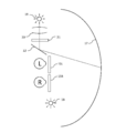
- FIG. 3 schematically shows the state.
- FIG. 3 is a diagram illustrating a method of using the visual inspection apparatus according to the present embodiment.
- the number of times the target (“O” in the figure) is presented for each of the left and right eyes is one time.
- the target may be presented a plurality of times.
- an interval of 1 second is provided after the presentation of the target once.
- both left and right eyes are presented with light for suppressing dark adaptation.
- the interval time may be appropriately set according to the situation. Also, whether or not to provide an interval may be set according to the situation as appropriate.
- a method for presenting the target a known method may be used. For example, a visual field map may be created by illuminating a predetermined portion of the image display 13 and confirming whether or not the subject can recognize the light. On the contrary, the light source of the predetermined part of the image display 13 may be turned off, the predetermined part may be particularly darkened, and it may be confirmed whether or not the subject can recognize the dark part.
- a target having a predetermined shape as listed above may be presented.
- the optotype presenting unit As a function of the optotype presenting unit, there is a function of performing a visual inspection on the other eye before ending the visual inspection on the other eye. This function achieves "suppression of learning effects” and “reduction of fatigue accumulation in one eye of a subject caused by continuing examination of one eye” and, in turn, “obtaining accurate test results”. It becomes possible.
- the inspection for the left eye L is performed by interrupting the inspection for the right eye R such as right eye ⁇ left eye ⁇ right eye.
- the right eye R is examined because the examination of the left eye L is performed before the examination of the right eye R is completed. It can be suppressed that the examination on the left eye L is excessively concentrated on the examination for the left eye L. Normally, even when the right eye R is being examined, the left eye L tries to see the visual target following the right eye R. However, conventionally, it is shielded by an eye patch or the like. As a result, the left eye L continues to be concentrated in the same manner as the right eye R, with the left eye L remaining in a state where it is not possible to see the target.
- the examination of the left eye L is continued with almost no break, even though the left eye L is also concentrated for 4 minutes with the examination of the right eye R for 4 minutes. turn into. If it becomes so, the test result of the left eye L will no longer be made based on a normal state.
- the examination for the other eye is started (in other words, the target is presented).
- the inspection is not performed in a state in which fatigue is biased to any eye. That is, the subject can be examined while maintaining the same level of concentration in the left and right eyes.
- the above functions will be further amplified if the brightness of the background light presented is the same for the left and right eyes.
- the brightness of the background light to be presented is the same for the left and right eyes and the visual inspection conditions for the left and right eyes are made to be the same, even if the target is presented to the subject, it is presented to the right eye R. It is almost impossible to discriminate whether the subject is present or presented to the left eye L.
- the operator of the apparatus can grasp which eye is presented to the left or right eye and can also grasp the result. If this happens, the subject will not have the preconception that "I am examining the eye of the person who feels uncomfortable now.” Also, there is no feeling that “the left eye examination still remains after the right eye examination is completed”.
- an optical system 14 may be provided between the image display display 13 and the subject's eye so that the subject can check the target. Further, as shown in FIG. 2, an optical system 14L for the left eye and an optical system 14R for the right eye may be provided.
- the configuration described in the above-described patent document may be used, or the optical system 14 of a known visual inspection apparatus may be used. Examples of such an optical system 14 include a combination of optical elements such as an eyepiece lens, an objective lens, and a mirror.
- a sensor for adjusting the luminous intensity As configurations other than the optical system 14, although not shown, a sensor for adjusting the luminous intensity, a dazzling generator, a dazzling backlight generator, and an exciter for displaying the target on the image display display 13. Is mentioned. Also included are a signal generator for intentionally indicating that the subject has confirmed the target during the examination, a memory for storing the signal, an examination monitor for displaying the result, and so on.
- Control computer unit 30 has a function as a computer device that performs information processing instructed by a predetermined program.
- the control computer unit 30 includes a CPU (Central Processing Unit), a HDD (Hard Disk Drive), and a ROM (Read Only Memory). ), RAM (Random Access Memory), an external interface (I / F), and the like.
- the control computer unit 30 may be incorporated in the housing 11 of the HMD unit 10 or may be provided separately from the HMD unit 10. When provided separately from the HMD unit 10, the control computer unit 30 can communicate with the HMD unit 10 via a wired or wireless communication line.
- FIG. 4 is a block diagram showing a relationship between the control computer unit 30 and the HMD unit 10 in the present embodiment.
- functions as the communication unit 31, the data acquisition unit 32, and the image generation unit 33 are realized by the control computer unit 30 executing a predetermined program (a visual inspection program described later). .
- the communication unit 31 has a function for the control computer unit 30 to communicate with the HMD unit 10. Specifically, the communication unit 31 sends a simulation image generated by an image generation unit 33 described later to the image display display 13. Note that the communication protocol used by the communication unit 31 is not particularly limited.
- the data acquisition unit 32 has a function for acquiring information about the subject.
- the acquired information may include physiological data of the subject such as age and sex. Such physiological data may be obtained, for example, when the data acquisition unit 32 in the control computer unit 30 accesses the data server device on the network line through a network line (not shown). Then, in accordance with the physiological data obtained by the data acquisition unit 32, the inspection conditions such as the brightness and color of the background light, the type of the target and the time for displaying the target, and the timing for displaying the target alternately for the left and right eyes Information may be set automatically.
- the subject to be examined may manually input physiological data, and in that case, the data acquisition unit 32 is not necessary.
- the image generation unit 33 is an image that the subject will see with each of the left eye L and the right eye R, and has a function of presenting an image in which background light and a visual target are superimposed.
- An examination image is generated based on physiological data and examination condition information obtained by the data acquisition unit 32, or physiological data and examination condition information input manually. Then, the generated image is displayed on the image display display 13.
- the communication unit 31, the data acquisition unit 32, and the image generation unit 33 described above are realized by the control computer unit 30 having a function as a computer device executing a visual inspection program (described later) in the present embodiment.
- the visual inspection program is installed and used in the HDD or the like of the control computer unit 30, but prior to the installation, the visual inspection program may be provided through a network line connected to the control computer unit 30, Alternatively, the program may be provided by being stored in a recording medium readable by the control computer unit 30.
- FIG. 5 is a flowchart showing a method of using the visual inspection apparatus according to this embodiment.
- the method of using the visual inspection apparatus can be broadly divided into a subject information acquisition step (S1), an inspection condition determination step (S2), a background light presentation step (S3), and a visual target presentation step for the right eye R ( 1/2) (S4), target presentation step for the left eye L (1/2) (S5), target presentation step for the right eye R (2/2) (S6), and target for the left eye L Presenting step (2/2) (S7).
- the subject information acquisition step (S1) information related to the subject is acquired by the data acquisition unit 32.
- the information about the subject is inquired to the data server device via the communication unit 31.
- the physiological data of the subject stored in the data server device is transmitted to the data acquisition unit 32 via the communication unit 31.
- the visual inspection apparatus may acquire the subject information when the operator manually inputs the subject information.
- the brightness and color of the background light, the type of the target and the time for displaying the target, and the left and right eyes are viewed alternately, corresponding to the physiological data obtained by the data acquisition unit 32.
- Inspection condition information such as the timing to present the mark is automatically set. Of course, the operator may arbitrarily manually determine the inspection conditions.
- the brightness and color of the light source of the image display 13 is determined based on the inspection condition information determined in the inspection condition determining step (S2).
- the same background light is presented not only on the image display display 13L corresponding to one eye (for example, the left eye L) but also on the image display display R corresponding to the other eye (right eye R). This creates a situation where both the left and right eyes are not dark-adapted.
- the optotype presenting step (1/2) (S4) for the right eye R first, the visual field inspection is performed for the right eye R.
- the timing for presenting the visual target alternately between the left and right eyes is set based on the inspection condition information determined in the inspection condition determination step (S2). After all, an inspection image is generated by the background light presenting step and the visual target presenting step. Then, after the target presentation step (1/2) (S4) for the right eye R is completed, the target presentation step (1/2) (S5) for the left eye L is performed. That is, the examination for the right eye R is only half completed at this point. After the examination for the right eye R is temporarily suspended, the examination for the left eye L is performed.
- the optotype presenting step (1/2) (S5) for the left eye L an examination similar to the examination for the right eye R is performed. Then, after the visual target presenting step (1/2) (S5) for the left eye L is completed, the visual target presenting step (2/2) (S6) for the right eye R is performed. That is, this time, the examination for the left eye L is temporarily suspended, and then the examination for the right eye R that has been suspended is resumed.
- the optotype presenting step (2/2) (S6) for the right eye R and the optotype presenting step (2/2) (S7) for the left eye L are performed in the same manner as (S4) and (S5). Thus, the visual field inspection for the left and right eyes is completed.
- the visual inspection apparatus having the above-described configuration has a great feature.
- a program and a recording medium that cause a computer device to function as a “dark adaptation suppression light presentation unit” and a “target presentation unit” also have significant characteristics.
- the control computer unit 30 instructs the dark adaptation suppression light presenting unit to present predetermined light.
- the control computer unit 30 instructs the target presenting unit to present the target under a predetermined condition.
- the contents of this command may be determined based on information about the subject acquired by the data acquisition unit 32. Similarly, based on the information, the content of the command may be reflected in the image generation unit 33 and the image may be displayed on the image display display 13.
- the background light is presented together with the visual target to the eye undergoing visual inspection. Even if there is another eye that has not been visually inspected, light for suppressing dark adaptation is presented to the other eye. As a result, first, it is possible to suppress a decrease in accuracy of the inspection result due to dark adaptation.
- a situation where light for suppressing dark adaptation is presented, that is, a situation where the left and right eyes are brightly adapted and the left and right eyes are ready for visual inspection.
- the visual target is presented to the eye of the subject so that the visual target is presented to the other eye before the visual inspection for one eye is completed.
- dark adaptation suppression light presentation unit By providing the optical system 14 with a configuration that is a part of the dark adaptation suppression light presenting unit, light for suppressing dark adaptation may be presented to the other eye that has not been visually inspected. Absent.
- dark adaptation suppression light presentation unit By providing the optical system 14 with a configuration that is a part of the dark adaptation suppression light presenting unit, light for suppressing dark adaptation may be presented to the other eye that has not been visually inspected. Absent.
- other examples of the dark adaptation suppression light presentation unit will be described.
- FIG. 6 is a schematic top view of another embodiment of the visual inspection apparatus using the polarizing film 13 ⁇ and the polarizer 15.
- the tip of the arrow is a schematic front view of the polarizing film 13 ⁇ .
- one image display display 13 is prepared.
- a polarizing film 13 ⁇ is attached to the image display display 13.
- This polarizing film 13 ⁇ has two types of polarization patterns (P-polarization pattern (reference P) and S-polarization pattern (reference S)).
- a P-polarization polarizer 15L is disposed between the left eye L and the optical system 14, and an S-polarization polarizer 15R is disposed between the right eye R and the optical system 14.
- the P-polarized background light is presented to the left eye L and the S-polarized background light is presented to the right eye R with respect to the background light emitted from one image display display 13. Therefore, even if a visual inspection is performed on one of the eyes, the other eye does not adapt to darkness.
- the target will be presented as follows.
- the optotype is presented to the left eye L
- the optotype is presented on the part having the P-polarized pattern on the polarizing film 13 ⁇ on the image display 13.
- the optotype is presented on the portion having the S polarization pattern.
- a P-polarization polarizer 15L may be disposed between the left eye L and the optical system 14, or an S-polarization polarizer 15L may be disposed. The same applies to the right eye R.
- the dark adaptation suppression light presentation unit includes the image display 13.
- the optotype presenting part includes the image display 13 on which the polarizing film 13 ⁇ is attached and the polarized light.
- FIG. 7 is a schematic top view of another embodiment of a visual inspection apparatus that uses a polarizer 15 and a polarizing beam splitter 16.
- one image display display 13a is prepared in front of the left and right eyes, and separately, the image displayed on the image display display 13a is in a mirror image relationship.
- An image display display 13b is separately prepared, and the polarization beam splitter 16 is disposed between the optical system 14 and the image display displays (13a, 13b).
- a P-polarizing polarizer 15 ⁇ / b> L is disposed between the left eye L and the optical system 14
- an S-polarizing polarizer 15 ⁇ / b> R is disposed between the right eye R and the optical system 14.
- the dark adaptation suppression light presentation unit and the target presentation unit include two image display displays (13a, 13b) and a polarization beam splitter 16.
- FIG. 8 is a schematic top view of another embodiment of a visual inspection apparatus using a polarizer and a polarization maintaining screen 17.
- the dark adaptation suppression light presenting unit prepares a non-polarized light source 18 while preparing one dome-shaped polarization holding screen 17 in front of the left and right eyes. Present both the left and right eyes with background light.
- the optotype presenting unit arranges a P-polarized polarizer 15L between the left eye L and the polarization holding screen 17, and an S-polarized polarizer 15R between the right eye R and the polarization holding screen 17.
- the light emitted from the light source 19 prepared separately from the dark adaptation suppression light presenting unit is reflected by the reflecting plate 22 through the optical system 20 and the target polarizer 21.
- the polarization holding screen 17 is irradiated.
- the visual target can be presented on the portion of the screen corresponding to a predetermined location in the visual field map.
- the dark adaptation suppression light presenting unit and the optotype presenting unit can exhibit their functions even in a configuration employing a screen common to the left and right eyes. Become.
- the dark adaptation suppression light presentation unit includes a non-polarized light source 18.
- the optotype presenting unit includes a light source, a polarizer 21 and a polarization holding screen 17 prepared separately from the dark adaptation suppression light presenting unit.
- FIG. 9 is a schematic top view of another embodiment of the visual inspection apparatus using the active shutter 23 and the time division display device 24.
- the light for suppressing dark adaptation presented from the image display 13 is not continuously presented to the eye, but the active shutter 23. Present intermittently. In this case, it is necessary to open and close the active shutter 23 at a cycle that does not allow the subject's eyes to darkly adapt.
- the target will be presented as follows. First, the target is presented on the time-division display device 24.
- the time division display device 24 always presents background light. However, the target is presented in a time-sharing manner. In other words, after the background light continues to be presented, the presentation and non-presentation of the target are alternately repeated. Assuming that the left eye L is to be inspected, when the target is presented to the left eye L, the left eye active shutter 23L is kept open. On the other hand, the active shutter 23R for the right eye that is not inspected is operated. At that time, the timing of the presentation and non-presentation of the visual target in the time division display device 24 and the timing of opening and closing the active shutter 23R for the right eye are synchronized.
- the active shutter for the right eye is used so that the target is not presented to the right eye R that has not been examined.
- 23R is set to close.
- the right-eye active shutter 23R is set to open so that the light for suppressing dark adaptation is presented to the right eye R.
- the dark adaptation suppression light presentation unit includes a time-division display device 24.
- the optotype presenting unit includes an active shutter 23 and a time division display device 24.
- FIG. 10 is a schematic top view of another embodiment of a visual inspection apparatus using an active shutter (23, 26) and a screen 25.
- the active shutter 23 may be applied to the screen system described in FIG.
- the presented target is passed from the target light source 19 through the optical system 20, passes through the target active shutter 26, is reflected by the reflecting plate 22, and is projected onto the screen 25.
- the active shutter 23R for the right eye and the active shutter 26 for the target are synchronized in opening and closing. That is, when the target active shutter 26 is open, the right-eye active shutter 23R is also open.
- the active shutter 23L for the left eye and the active shutter 26 for the target are displaced at the opening / closing timing. That is, when the visual target active shutter 26 is open, the left-eye active shutter 23L is closed. By doing so, it is possible to present the visual target only to the right eye R. Moreover, since the light for suppressing dark adaptation is irradiated in the inspection apparatus, dark adaptation can be suppressed for the left eye L that has not been inspected.
- the dark adaptation suppression light presentation unit includes a non-polarized light source 18.
- the visual target presenting unit includes a light source 19, an active shutter (23, 26), and a screen 25 prepared separately from the dark adaptation suppression light presenting unit.
- a method using the polarizer (15, 21), a method using the active shutter (23, 26), and a combination thereof may be applied to the above-described embodiment using the image display display 13. Absent.
- a method using a polarizer (15, 21), a method using an active shutter (23, 26), and a combination thereof may be applied to a method using a screen (17, 25). Absent.
- the present invention can be applied to an eyesight inspection apparatus.
- An image display (13L, 13R) that presents light for suppressing dark adaptation to both eyes (L, R) of the subject;
- the target is presented to the eye (L, R, or both) of the subject so that the target is presented to the other eye R before the visual inspection of one eye L is completed.
- An image display (13L, 13R) Visual inspection apparatus having
- SYMBOLS 10 HMD part, 11 ... Housing
Landscapes
- Life Sciences & Earth Sciences (AREA)
- Health & Medical Sciences (AREA)
- Medical Informatics (AREA)
- Biophysics (AREA)
- Ophthalmology & Optometry (AREA)
- Engineering & Computer Science (AREA)
- Biomedical Technology (AREA)
- Heart & Thoracic Surgery (AREA)
- Physics & Mathematics (AREA)
- Molecular Biology (AREA)
- Surgery (AREA)
- Animal Behavior & Ethology (AREA)
- General Health & Medical Sciences (AREA)
- Public Health (AREA)
- Veterinary Medicine (AREA)
- Eye Examination Apparatus (AREA)
Abstract
Description
本発明の一つの態様は、
被検者の両眼に対して暗順応を抑制するための光を呈示する暗順応抑制光呈示部と、
一方の眼に対する視覚検査が終了する前にもう一方の眼に対しても視標の呈示が行われるように、被験者の眼に対して視標を呈示する視標呈示部と、
を有する視覚検査装置である。
本実施形態においては、次の順序で説明を行う。
1.視覚検査装置
A)HMD部
a.画像表示ディスプレイ(暗順応抑制光呈示部&視標呈示部)
b.その他(光学系等)
B)制御コンピュータ部
2.HMD部と制御コンピュータ部との間の関係
3.視覚検査装置の使用方法
4.視覚検査プログラム及び記録媒体
5.実施の形態による効果
6.変形例等
なお、以下に記載が無い構成については、公知の視覚検査装置を用いても構わない。例えば、特許文献1(特開平9-47430号公報)や特開平7-67833に記載された構成を適宜採用しても構わない。
本実施形態においては、視覚検査装置がHMDである場合について述べる。図1は、本実施形態の視覚検査装置の概略図である。本実施形態の視覚検査装置は、大別すると、図1に示すように、ヘッドマウントディスプレイ(HMD)部10と、制御コンピュータ部30とを備えて構成されている。そして、HMD部10は、暗順応抑制光呈示部と視標呈示部とを有しているが、本実施形態においては、暗順応抑制光呈示部と視標呈示部とが画像表示ディスプレイ13にまとめられている場合について述べる。
HMD部10は、筐体11とこれに接続された装着バンド12とを備えており、これらにより視覚検査の被検者(以降、単に「被検者」と言う。)の頭部に装着することが可能に構成されている。そして、筐体11には、暗順応抑制光呈示部と視標呈示部とが組み込まれている。本実施形態においては、左右眼各々のために設けられた画像表示ディスプレイ(13L,13R)が暗順応抑制光呈示部と視標呈示部とを兼ねている場合について述べる。以降、13Lは左眼用の画像表示ディスプレイ、13Rは右眼用の画像表示ディスプレイとしつつ、(13L,13R)をまとめて「画像表示ディスプレイ13」と表記する。
画像表示ディスプレイ13を図2にて概略的に示す。図2は、本実施形態の視覚検査装置の上面概略図である。
画像表示ディスプレイ13は、HMD部10の筐体11を装着した被検者の眼の前方に配されて、当該被検者に対する画像表示を行うものである。画像表示ディスプレイ13は、例えばLCD(Liquid Crystal Display)を利用して構成されたものを用いることが考えられる。このような画像表示ディスプレイ13が表示出力する画像としては、詳細を後述するように、背景光と視標とを合わせたものが挙げられる。
更に言うと、動かない光の点(視標)を背景光に対して表示するような静的視野測定のみならず、視標を動く光の点とした動的視野測定を行っても構わない。
上述の通り、本実施形態においては、画像表示ディスプレイ(13L,13R)が暗順応抑制光呈示部と視標呈示部とを兼ねている。本実施形態における暗順応抑制光呈示部は、暗順応を抑制するための光(即ち背景光)を呈示するものである。そして、この光は、左右眼に対して光を呈示するものである。別の言い方をすると、被検者の左右眼のうち一方の眼に対する視覚検査が行われている際、仮に、もう一方の眼に対しては視覚検査が行われていないとすると、当該もう一方の眼に対しても、暗順応を抑制するための光を呈示するものである。
本実施形態における視標呈示部は、一方の眼に対する視覚検査が終了する前にもう一方の眼に対しても視標の呈示が行われるように、被検者の眼に対して視標を呈示する部分である。
HMD部10において、画像表示ディスプレイ13と被検者の眼との間に、被検者が視標を確認することが可能となるような光学系14を設けても構わない。また、図2に記載のように、左眼用の光学系14L及び右眼用の光学系14Rを各々設けても構わない。この光学系14としては、上述の特許文献に記載されている構成を用いても構わないし、その他、公知の視覚検査装置の光学系14を用いても構わない。このような光学系14としては、接眼レンズ、対物レンズ、ミラー等の光学要素の組み合わせが挙げられる。
制御コンピュータ部30は、所定プログラムで指示された情報処理を行うコンピュータ装置としての機能を有するものであり、具体的にはCPU(Central Processing Unit)、HDD(Hard disk drive)、ROM(Read Only Memory)、RAM(Random Access Memory)、外部インタフェース(I/F)等の組み合わせによって構成されたものである。なお、制御コンピュータ部30は、HMD部10の筐体11に組み込まれたものであってもよいし、HMD部10とは別体で設けられたものであってもよい。HMD部10と別体で設けられる場合、制御コンピュータ部30は、HMD部10との間で、有線又は無線の通信回線を介して、通信を行うことが可能になっているものとする。
続いて、本実施形態における、制御コンピュータ部30とHMD部10との間の関係について説明する。
図4は、本実施形態における、制御コンピュータ部30とHMD部10との間の関係を示すブロック図である。
続いて、本実施形態における視覚検査装置の使用方法について説明する。
図5は、本実施形態における視覚検査装置の使用方法を示すフローチャートである。
そして、右眼Rに対する視標呈示ステップ(1/2)(S4)が終了した後、左眼Lに対する視標呈示ステップ(1/2)(S5)を行う。つまり、右眼Rに対する検査は、この時点では半分しか終わっていない。右眼Rに対する検査を一時中断した上で、左眼Lに対する検査を行う。
本実施形態においては、上記の構成を有する視覚検査装置に大きな特徴がある。その一方、コンピュータ装置を「暗順応抑制光呈示部」及び「視標呈示部」として機能させるプログラム及び記録媒体にも、大きな特徴がある。この場合、具体的な運用方法としては、制御コンピュータ部30が、暗順応抑制光呈示部に対して所定の光を呈示するよう命令する。同様に、制御コンピュータ部30が、視標呈示部に対して所定の条件で視標を呈示するよう命令する。この命令の内容は、データ取得部32により取得された被検者に関する情報に基づいて決定しても構わない。同様に、当該情報に基づき、命令の内容を画像生成部33に反映させ、その画像を画像表示ディスプレイ13に表示しても構わない。
本実施形態においては、視覚検査が行われている眼には自ずと視標とともに背景光が呈示されている。そして、仮に、視覚検査が行われていないもう一方の眼が存在するとしても、当該もう一方の眼に対しては、暗順応を抑制するための光が呈示されている。その結果、まずは、暗順応に起因する検査結果の精度の低下を抑制することが可能となる。
本発明は、上述した実施形態の内容に限定されることはなく、その要旨を逸脱しない範囲で適宜変更することが可能である。
以下、暗順応抑制光呈示部の他の例について説明する。
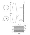
まず、図6を用いて説明する。図6は、偏光フィルム13α及び偏光子15を使用した、別の実施形態の視覚検査装置の上面概略図である。矢印の先は、偏光フィルム13αの正面概略図である。
図6に示すように、上記の実施形態とは異なり、1つの画像表示ディスプレイ13を用意する。そして、画像表示ディスプレイ13に対し、偏光フィルム13αを貼り付ける。この偏光フィルム13αは、2種類の偏光パターン(P偏光パターン(符号P)、S偏光パターン(符号S))を有している。そして、左眼Lと光学系14との間にP偏光用の偏光子15L、そして右眼Rと光学系14との間にS偏光用の偏光子15Rを配置する。こうすることにより、1つの画像表示ディスプレイ13により発せられる背景光に対し、左眼LにはP偏光の背景光が呈示され、右眼RにはS偏光の背景光が呈示される。そのため、いずれか一方の眼に対し視覚検査が行われていても、もう一方の眼が暗順応することがなくなる。
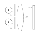
次に、図7を用いて説明する。図7は、偏光子15及び偏光ビームスプリッタ16を使用した、別の実施形態の視覚検査装置の上面概略図である。
図7に示すように、上記の実施形態とは異なり、左右眼の正面に1つの画像表示ディスプレイ13aを用意し、それとは別に、画像表示ディスプレイ13aに表示される画像が鏡像関係となるような画像表示ディスプレイ13bを別途用意し、光学系14と画像表示ディスプレイ(13a,13b)との間に偏光ビームスプリッタ16を配置する。その上で、左眼Lと光学系14との間にP偏光用の偏光子15L、そして右眼Rと光学系14との間にS偏光用の偏光子15Rを配置する。こうすることにより、例えば、左眼Lには、P偏光用の偏光子15L及び偏光ビームスプリッタ16によって、別途用意された画像表示ディスプレイ13bの背景光及び視標が呈示される。その一方、右眼Rには、S偏光用の偏光子15R及び偏光ビームスプリッタ16によって、左右眼の正面の画像表示ディスプレイ13aの背景光及び視標が呈示される。
次に、図8を用いて説明する。図8は、偏光子及び偏光保持スクリーン17を使用した、別の実施形態の視覚検査装置の上面概略図である。
図8に示すように、上記の実施形態とは異なり、左右眼の正面に1つのドーム型の偏光保持スクリーン17を用意しつつ、暗順応抑制光呈示部は無偏光の光源18を用意して左右眼に共に背景光を呈示する。そして、視標呈示部は、左眼Lと偏光保持スクリーン17との間にP偏光用の偏光子15L、そして右眼Rと偏光保持スクリーン17との間にS偏光用の偏光子15Rを配置したものであり、且つ、暗順応抑制光呈示部とは別に用意された光源19から発せられた光が光学系20及び視標用の偏光子21を通過した光を、反射板22にて反射して偏光保持スクリーン17に照射するものであるという構成を有している。反射板22の角度を変動させることにより、視野マップにおける所定の場所に対応するスクリーンの部分に視標を呈示することができる。左右眼の各々に対して画像表示ディスプレイ13を設けなくとも、左右眼に共通したスクリーンを採用した構成でも、暗順応抑制光呈示部及び視標呈示部はそれらの機能を発揮することが可能となる。
次に、図9を用いて説明する。図9は、アクティブシャッター23及び時分割表示装置24を使用した、別の実施形態の視覚検査装置の上面概略図である。
図9に示すように、上記の実施形態とは異なり、画像表示ディスプレイ13から呈示される暗順応を抑制するための光を、眼に対して連続的に呈示し続けるのではなく、アクティブシャッター23により断続的に呈示する。この場合、被検者の眼が暗順応しない程度の周期でアクティブシャッター23の開閉を行う必要がある。
最後に、図10を用いて説明する。図10は、アクティブシャッター(23,26)及びスクリーン25を使用した、別の実施形態の視覚検査装置の上面概略図である。
図10に示すように、アクティブシャッター23を、図8に記載されたスクリーン方式に応用しても構わない。呈示される視標は、視標用の光源19から光学系20を経て、視標用のアクティブシャッター26を通過し、反射板22にて反射され、スクリーン25に投影される。右眼Rを検査する場合について考えると、右眼用のアクティブシャッター23Rと、視標用のアクティブシャッター26とを、開閉において同期させている。つまり、視標用のアクティブシャッター26が開いているとき、右眼用のアクティブシャッター23Rも開いている。その一方、左眼用のアクティブシャッター23Lと、視標用のアクティブシャッター26とを、開閉のタイミングにおいてずれを生じさせている。つまり、視標用のアクティブシャッター26が開いているとき、左眼用のアクティブシャッター23Lは閉じている。こうすることにより、右眼Rだけに対して視標を呈示することができる。その上、暗順応を抑制するための光は、検査装置内に照射されているため、検査を行っていない左眼Lに対して暗順応を抑制することができる。
被検者の両眼(L,R)に対して暗順応を抑制するための光を呈示する画像表示ディスプレイ(13L,13R)と、
一方の眼Lに対する視覚検査が終了する前にもう一方の眼Rに対して視標の呈示が行われるように、被検者の眼(L,R,又は両方)に対して視標を呈示する画像表示ディスプレイ(13L,13R)と、
を有する視覚検査装置。
Claims (5)
- 被検者の両眼に対して暗順応を抑制するための光を呈示する暗順応抑制光呈示部と、
一方の眼に対する視覚検査が終了する前にもう一方の眼に対しても視標の呈示が行われるように、被検者の眼に対して視標を呈示する視標呈示部と、
を有する視覚検査装置。 - 前記暗順応抑制光呈示部は、両眼各々に同じ明るさの背景光を呈示するものである請求項1に記載の視覚検査装置。
- 前記暗順応抑制光呈示部及び前記視標呈示部は、被検者の頭部に装着可能な筐体に組み込まれている請求項1又は2に記載の視覚検査装置。
- 被検者の両眼に対して暗順応を抑制するための光を呈示する暗順応抑制光呈示部、及び、
一方の眼に対する視覚検査が終了する前にもう一方の眼に対しても視標の呈示が行われるように、被検者の眼に対して視標を呈示する視標呈示部、
としてコンピュータ装置を機能させる視覚検査プログラム。 - 前記暗順応抑制光呈示部は、両眼各々に同じ明るさの背景光を呈示するものである請求項4に記載の視覚検査プログラム。
Priority Applications (3)
| Application Number | Priority Date | Filing Date | Title |
|---|---|---|---|
| PCT/JP2014/061934 WO2015166548A1 (ja) | 2014-04-30 | 2014-04-30 | 視覚検査装置及び視覚検査プログラム |
| EP14890769.4A EP3138471B1 (en) | 2014-04-30 | 2014-04-30 | Vision testing device and vision testing program |
| US15/307,904 US10130251B2 (en) | 2014-04-30 | 2014-04-30 | Vision testing device and vision testing program |
Applications Claiming Priority (1)
| Application Number | Priority Date | Filing Date | Title |
|---|---|---|---|
| PCT/JP2014/061934 WO2015166548A1 (ja) | 2014-04-30 | 2014-04-30 | 視覚検査装置及び視覚検査プログラム |
Publications (1)
| Publication Number | Publication Date |
|---|---|
| WO2015166548A1 true WO2015166548A1 (ja) | 2015-11-05 |
Family
ID=54358301
Family Applications (1)
| Application Number | Title | Priority Date | Filing Date |
|---|---|---|---|
| PCT/JP2014/061934 WO2015166548A1 (ja) | 2014-04-30 | 2014-04-30 | 視覚検査装置及び視覚検査プログラム |
Country Status (3)
| Country | Link |
|---|---|
| US (1) | US10130251B2 (ja) |
| EP (1) | EP3138471B1 (ja) |
| WO (1) | WO2015166548A1 (ja) |
Families Citing this family (2)
| Publication number | Priority date | Publication date | Assignee | Title |
|---|---|---|---|---|
| JP2022502221A (ja) | 2018-09-21 | 2022-01-11 | マクロジックス インコーポレイテッドMaculogix, Inc. | 眼球検査及び測定を行う方法、装置並びにシステム |
| CN109188700B (zh) * | 2018-10-30 | 2021-05-11 | 京东方科技集团股份有限公司 | 光学显示系统及ar/vr显示装置 |
Citations (3)
| Publication number | Priority date | Publication date | Assignee | Title |
|---|---|---|---|---|
| JPH05245105A (ja) * | 1991-03-25 | 1993-09-24 | Yukio Okuzawa | 遮閉下での眼位検査法 |
| JP2012213633A (ja) * | 2011-03-31 | 2012-11-08 | Nidek Co Ltd | 視標呈示装置 |
| JP2013063318A (ja) * | 2012-12-10 | 2013-04-11 | Panasonic Corp | 提示方法 |
Family Cites Families (12)
| Publication number | Priority date | Publication date | Assignee | Title |
|---|---|---|---|---|
| US3891311A (en) * | 1971-07-07 | 1975-06-24 | Nasa | Multiparameter vision testing apparatus |
| DE69111881T2 (de) * | 1990-04-28 | 1995-12-07 | Nidek Kk | Gerät zum Messen des Sehvermögens. |
| JPH08140933A (ja) | 1994-11-18 | 1996-06-04 | Browning Johannes | 視覚機能の検査装置及び検査方法 |
| JP3602214B2 (ja) | 1995-08-07 | 2004-12-15 | 株式会社ニデック | 検眼装置 |
| US6578965B2 (en) * | 2001-07-02 | 2003-06-17 | Alan H. Grant | Objective system and method for evaluating ocular changes including assessment of macular integrity and function |
| ES2563733T3 (es) * | 2003-09-04 | 2016-03-16 | The Uab Research Foundation | Procedimiento y aparato para la detección del deterioro en la adaptación a la oscuridad |
| US8684946B1 (en) * | 2005-12-19 | 2014-04-01 | The Uab Research Foundation | Method and apparatus for determining the sensitivity of cone photoreceptors and uses thereof |
| AU2008216683B2 (en) * | 2007-02-15 | 2014-05-01 | The Uab Research Foundation | Improved photobleaching method |
| WO2011016029A2 (en) * | 2009-08-02 | 2011-02-10 | Tel Hashomer Medical Research Infrastructure And Services Ltd | System and method for objective chromatic perimetry analysis using pupillometer |
| CN201790795U (zh) * | 2010-09-03 | 2011-04-13 | 济南爱普特科技贸易有限公司 | 一种军车驾驶员职业适性检测系统 |
| US8992019B2 (en) * | 2012-01-06 | 2015-03-31 | Baylor College Of Medicine | System and method for evaluating ocular health |
| US9681805B2 (en) * | 2012-11-05 | 2017-06-20 | Babak Kamkar | Afferent pupil tester |
-
2014
- 2014-04-30 EP EP14890769.4A patent/EP3138471B1/en active Active
- 2014-04-30 US US15/307,904 patent/US10130251B2/en active Active
- 2014-04-30 WO PCT/JP2014/061934 patent/WO2015166548A1/ja active Application Filing
Patent Citations (3)
| Publication number | Priority date | Publication date | Assignee | Title |
|---|---|---|---|---|
| JPH05245105A (ja) * | 1991-03-25 | 1993-09-24 | Yukio Okuzawa | 遮閉下での眼位検査法 |
| JP2012213633A (ja) * | 2011-03-31 | 2012-11-08 | Nidek Co Ltd | 視標呈示装置 |
| JP2013063318A (ja) * | 2012-12-10 | 2013-04-11 | Panasonic Corp | 提示方法 |
Also Published As
| Publication number | Publication date |
|---|---|
| US10130251B2 (en) | 2018-11-20 |
| US20170065166A1 (en) | 2017-03-09 |
| EP3138471A1 (en) | 2017-03-08 |
| EP3138471A4 (en) | 2017-11-29 |
| EP3138471B1 (en) | 2021-04-21 |
Similar Documents
| Publication | Publication Date | Title |
|---|---|---|
| JP6013887B2 (ja) | 視覚検査装置及び視覚検査プログラム | |
| JP5826902B2 (ja) | 視覚検査装置及び視覚検査プログラム | |
| EP3238607A1 (de) | Verfahren und vorrichtungen zur bestimmung der augenrefraktion | |
| EP3295864B1 (en) | Apparatus for assisting in establishing a correction for correcting heterotropia or heterophoria and method of operating a computer for assisting in establishing a correction for correcting heterotropia or heterophoria | |
| JP6964250B2 (ja) | 眼球撮影装置および眼球撮影方法 | |
| US20090073386A1 (en) | Enhanced head mounted display | |
| US11363948B2 (en) | Ophthalmologic device and method of operating ophthalmologic device | |
| JP2018110726A (ja) | 自覚式検眼装置及び自覚式検眼プログラム | |
| JPH08140933A (ja) | 視覚機能の検査装置及び検査方法 | |
| JP2004298251A (ja) | 眼機能訓練方法及び眼機能訓練装置 | |
| Northway et al. | Coloured filters improve exclusion of perceptual noise in visually symptomatic dyslexics | |
| JP2017124173A (ja) | 検眼システムおよび検眼方法 | |
| WO2015166548A1 (ja) | 視覚検査装置及び視覚検査プログラム | |
| EP2416696B1 (en) | Optometric testing system | |
| WO2009075385A1 (ja) | 視野検査方法および装置 | |
| JP6529862B2 (ja) | 眼検査装置 | |
| JP2003093344A (ja) | 検眼装置 | |
| US7166079B2 (en) | Methods and apparatus for observing and recording irregularities of the macula and nearby retinal field | |
| JP2006203440A (ja) | 外界光透過型ヘッドマウントディスプレイ | |
| US20180014723A1 (en) | Image display apparatus, method of processing, and processing apparatus | |
| WO2015016233A1 (ja) | 診断支援装置および診断支援方法 | |
| Miller | Ocular vergence-induced accommodation and its relation to dark focus | |
| WO2019172285A1 (ja) | 視覚検査装置及び視覚検査プログラム | |
| JP5864794B1 (ja) | 視能訓練装置 | |
| GB2375821A (en) | Automatic vision testing system for children |
Legal Events
| Date | Code | Title | Description |
|---|---|---|---|
| 121 | Ep: the epo has been informed by wipo that ep was designated in this application |
Ref document number: 14890769 Country of ref document: EP Kind code of ref document: A1 |
|
| REEP | Request for entry into the european phase |
Ref document number: 2014890769 Country of ref document: EP |
|
| WWE | Wipo information: entry into national phase |
Ref document number: 2014890769 Country of ref document: EP |
|
| NENP | Non-entry into the national phase |
Ref country code: DE |
|
| WWE | Wipo information: entry into national phase |
Ref document number: 15307904 Country of ref document: US |
|
| NENP | Non-entry into the national phase |
Ref country code: JP |