WO2015163343A1 - 弁体、ダイヤフラム弁、ダイヤフラムポンプ、および送液ユニット - Google Patents
弁体、ダイヤフラム弁、ダイヤフラムポンプ、および送液ユニット Download PDFInfo
- Publication number
- WO2015163343A1 WO2015163343A1 PCT/JP2015/062182 JP2015062182W WO2015163343A1 WO 2015163343 A1 WO2015163343 A1 WO 2015163343A1 JP 2015062182 W JP2015062182 W JP 2015062182W WO 2015163343 A1 WO2015163343 A1 WO 2015163343A1
- Authority
- WO
- WIPO (PCT)
- Prior art keywords
- valve
- diaphragm
- ink
- valve body
- flow path
- Prior art date
- Legal status (The legal status is an assumption and is not a legal conclusion. Google has not performed a legal analysis and makes no representation as to the accuracy of the status listed.)
- Ceased
Links
Images





Classifications
-
- F—MECHANICAL ENGINEERING; LIGHTING; HEATING; WEAPONS; BLASTING
- F04—POSITIVE - DISPLACEMENT MACHINES FOR LIQUIDS; PUMPS FOR LIQUIDS OR ELASTIC FLUIDS
- F04B—POSITIVE-DISPLACEMENT MACHINES FOR LIQUIDS; PUMPS
- F04B43/00—Machines, pumps, or pumping installations having flexible working members
- F04B43/02—Machines, pumps, or pumping installations having flexible working members having plate-like flexible members, e.g. diaphragms
-
- F—MECHANICAL ENGINEERING; LIGHTING; HEATING; WEAPONS; BLASTING
- F04—POSITIVE - DISPLACEMENT MACHINES FOR LIQUIDS; PUMPS FOR LIQUIDS OR ELASTIC FLUIDS
- F04B—POSITIVE-DISPLACEMENT MACHINES FOR LIQUIDS; PUMPS
- F04B53/00—Component parts, details or accessories not provided for in, or of interest apart from, groups F04B1/00 - F04B23/00 or F04B39/00 - F04B47/00
- F04B53/10—Valves; Arrangement of valves
-
- F—MECHANICAL ENGINEERING; LIGHTING; HEATING; WEAPONS; BLASTING
- F16—ENGINEERING ELEMENTS AND UNITS; GENERAL MEASURES FOR PRODUCING AND MAINTAINING EFFECTIVE FUNCTIONING OF MACHINES OR INSTALLATIONS; THERMAL INSULATION IN GENERAL
- F16K—VALVES; TAPS; COCKS; ACTUATING-FLOATS; DEVICES FOR VENTING OR AERATING
- F16K7/00—Diaphragm valves or cut-off apparatus, e.g. with a member deformed, but not moved bodily, to close the passage ; Pinch valves
- F16K7/12—Diaphragm valves or cut-off apparatus, e.g. with a member deformed, but not moved bodily, to close the passage ; Pinch valves with flat, dished, or bowl-shaped diaphragm
- F16K7/14—Diaphragm valves or cut-off apparatus, e.g. with a member deformed, but not moved bodily, to close the passage ; Pinch valves with flat, dished, or bowl-shaped diaphragm arranged to be deformed against a flat seat
- F16K7/16—Diaphragm valves or cut-off apparatus, e.g. with a member deformed, but not moved bodily, to close the passage ; Pinch valves with flat, dished, or bowl-shaped diaphragm arranged to be deformed against a flat seat the diaphragm being mechanically actuated, e.g. by screw-spindle or cam
Definitions
- the present invention relates to a valve body, a diaphragm valve, a diaphragm pump, and a liquid feeding unit that can be suitably applied to liquid feeding exemplified by ink.
- ink jet recording apparatuses having various configurations are known for ejecting liquid (ink) from nozzles of an ink jet head and recording (printing) desired characters and figures on a recording medium.
- ink stored in an ink supply chamber of an ink jet head gradually decreases due to printing, that is, ink ejection from a nozzle, and thus it is necessary to supply ink to the ink supply chamber. Therefore, research and development have been conventionally conducted on pumps used for supplying ink.
- Patent Document 1 discloses a fuel pump that uses a diaphragm as a device for supplying fuel to an automobile engine. ing.
- the inventors of the present application have a diaphragm valve that can respond to a very small differential pressure of liquid (ink) as a liquid feeding device (ink supply device) in an ink jet recording apparatus, and is suitable for transferring a small amount of ink. Worked on pump research and development.
- An object of the present invention is to provide a valve body of a diaphragm valve that can be reliably performed, the diaphragm valve, a diaphragm pump using the diaphragm valve, and a liquid feeding unit.
- the valve body disclosed below is a valve body of a diaphragm valve that allows fluid to pass only in a predetermined direction in the flow path, and is compressed in the thickness direction and held in the valve box of the diaphragm valve,
- a central portion provided with a seating portion that is elastically displaced in the thickness direction in response to a differential pressure of the fluid and has one surface side closely attached to or separated from the valve seat portion of the valve box, and between the outer peripheral portion and the central portion.
- An intermediate portion having a hole portion through which a fluid can pass, wherein the intermediate portion has one or more cross-sectional shapes when cut along a plane parallel to the radial direction and parallel to the thickness direction, or It is formed into a shape having a plurality of curved portions or bent portions.
- the outer peripheral portion of the valve body of the diaphragm valve in a compressed state (crushed) in the thickness direction of the diaphragm has a larger outer diameter and a smaller inner diameter compared to the uncompressed state.
- the inner diameter of the outer peripheral portion is reduced, so that the intermediate portion is pushed from the outer side (outer edge side) to the inner side (center side) in the radial direction.
- the center part is pushed and moved.
- the arrangement of the center part (particularly the arrangement of the seating part) that is originally set in parallel with the radial direction is inclined with respect to the valve seat part so that it does not face the valve seat part. This is a cause of deformation. Research has revealed that this deformation causes a closing failure in which the entire circumference of the seating portion of the central portion cannot be brought into close contact with the valve seat portion, resulting in a liquid non-return failure.
- the intermediate portion having the curved portion or the bent portion is configured as a portion that can be easily deformed in the radial direction. That is, when the outer peripheral part is compressed and the intermediate part is pushed from the outside in the radial direction to the inside, the bending part or the bent part is easily deformed, and the force by which the intermediate part pushes the center part is reduced. It becomes possible to do. Therefore, it is possible to prevent deformation such as the central portion being inclined, and the close contact between the seating portion and the valve seat portion can be reliably performed, thereby reliably preventing poor closing. It becomes possible. Further, since the intermediate portion can be easily deformed, the central portion (sitting portion) can operate in response to a small differential pressure of the liquid.
- the valve body of the diaphragm valve which can respond to the very small differential pressure
- FIG. 1 is a schematic view (perspective view) of an ink jet recording apparatus in which a valve body, a diaphragm valve, a diaphragm pump, and a liquid feeding unit according to the present embodiment are mounted.
- FIG. 2 is a schematic view (perspective view) around a head unit of the ink jet recording apparatus shown in FIG. 1. It is the schematic which shows the example of the apparatus structure of the ink tank, diaphragm pump, and head unit which are mounted in the inkjet recording device shown in FIG. It is the schematic (perspective view) of the diaphragm pump by which a diaphragm valve provided with the valve body which concerns on this embodiment is arrange
- FIG. 5 is an exploded view (perspective view) of the diaphragm pump shown in FIG. 4. It is the figure which showed the exploded view (perspective view) of the main components in the diaphragm pump shown in FIG. 4 with the reverse view.
- FIG. 9 is a cross-sectional view (sectional view taken along line IX-IX) of the valve body shown in FIG.
- IX-IX cross-sectional view taken along line IX-IX
- the diaphragm pump 1 (see FIG. 5) in which the diaphragm valves 3 and 4 including the valve bodies 31 and 32 according to the present embodiment are disposed is mounted on the liquid feeding unit 2 of the ink jet recording apparatus 10, and the liquid feeding is performed.
- the present invention is applied as an apparatus, ie, an ink supply apparatus will be described as an example.
- the diaphragm pump 1 can be mounted other than the ink jet recording apparatus, and can be applied to liquid feeding other than ink.
- FIG. 1 is a schematic view (perspective view) of an ink jet recording apparatus 10 in which a diaphragm pump 1 according to this embodiment is mounted.
- FIG. 2 is a schematic view (perspective view) around the head unit 23 of the inkjet recording apparatus 10.
- FIG. 3 is a schematic diagram showing the device configuration of the ink tank 18, the diaphragm pump 1, and the recording head 25 mounted on the inkjet recording apparatus 10.
- front and rear, left and right, and up and down directions of the ink jet recording apparatus 10 are indicated by arrow directions in each drawing.
- members having the same function are denoted by the same reference numerals, and repeated description thereof may be omitted.
- a diaphragm pump for an automobile exemplified in Patent Document 1 cannot be used as it is as a diaphragm pump for an ink jet recording apparatus.
- the reason for this is that, in the case of a diaphragm pump that supplies fuel to a fuel pump of an automobile, robustness is important, and a discharge pressure of several kgf / cm 2 and a discharge amount of 100 liters / hour or more are required. This is because it is normal.
- valve bodies 31 and 32 of the diaphragm valves 3 and 4 must be formed flexibly so that the flow path can be opened and closed according to the flow of a very small amount of liquid (ink)” In doing so, we worked on solving the trade-off problem that the seating (closure) failure is likely to occur due to the effect of distortion.
- the ink jet recording apparatus 10 includes a recording head (ink jet head) 25 with respect to a recording surface (printing surface) of a recording medium M such as paper, cloth, resin sheet (for example, made of vinyl chloride, polyester, or the like).
- a recording head ink jet head
- This is a device that prints characters, figures, and the like by ejecting liquid (here, ink) from the nozzles.
- ink various inks such as UV ink cured by UV (ultraviolet) irradiation, aqueous ink such as aqueous sublimation transfer ink, or solvent-based ink such as solvent ink can be used.
- the inkjet recording apparatus 10 includes a central body portion 12 supported by a support leg 11, a left body portion 13 provided on the left side of the central body portion 12, and a center.
- the right body part 14 provided on the right side of the body part 12 and the upper body part 15 connected to the left and right body parts 13 and 14 and provided on the upper side of the central body part 12 are configured.
- the central body portion 12 is provided with a platen 29 on which the recording medium M is placed. Printing is performed by placing the recording medium M on the platen 29 and ejecting ink from a recording head 25 described later. Is done.
- the left body portion 13 is provided with operation switches and display devices on the front side thereof, and a left / right moving mechanism (a motor, belt, etc.) that moves a head unit 23 (see FIG. 2) described later to the left and right inside the left body portion 13. (Not shown), a maintenance station (not shown) for cleaning the head unit 23, and a control unit 28 as control means for controlling the operation of each component are provided.
- a left / right moving mechanism a motor, belt, etc.
- a maintenance station (not shown) for cleaning the head unit 23, and a control unit 28 as control means for controlling the operation of each component are provided.
- a guide rail 16 extending left and right is provided inside the upper body portion 15, and a head unit 23 is attached to the guide rail 16 so as to be movable left and right.
- the head unit 23 is driven by a left-right moving mechanism and is reciprocated left and right along the guide rail 16 inside the upper body portion 15.
- the head unit 23 is mainly configured by a recording head 25 and a carriage 24 that fixes the recording head 25 and performs a moving action on the guide rail 16.
- a plurality of recording heads 25 are provided for each ink color to be set.
- the recording head 25 includes a magenta recording head 25A, a yellow recording head 25B, a cyan recording head 25C, and a black recording head 25D.
- a plurality of nozzles are formed on the lower surface of each recording head 25 (25A to 25D) to eject ink toward the recording medium M placed below.
- a cartridge mounting portion 17 is provided inside the right body portion 14, and a cartridge type ink tank 18 in which ink is stored is disposed in front of the cartridge mounting portion 17. It is detachably attached from the side.
- a plurality of ink tanks are provided for each ink color.
- the ink tank 18 includes a magenta ink tank 18A, a yellow ink tank 18B, a cyan ink tank 18C, and a black ink tank 18D (see FIG. 3).
- the ink tank 18 (18A to 18D) is not limited to the cartridge type.
- connection portion 19 (a connection portion 19A corresponding to each ink color) that receives the ink tank 18 (18A to 18D) and receives ink.
- an ink tube 20 (ink tubes 20A to 20D corresponding to each ink color) provided in the right body portion 14 and the upper body portion 15 and an ink tube 21 are provided.
- Ink tubes 21A to 21D corresponding to the respective ink colors are connected to the recording heads 25 (25A to 25D) corresponding to the respective colors, and the ink in the ink tanks 18 (18A to 18D) is transferred to the ink tubes 20 (20A to 20A).
- 20D) and 21 (21A to 21D) to be supplied to an ink supply chamber (not shown) in the recording head 25 (25A to 25D).
- a diaphragm pump 1 as a supply device is provided between each ink tube 20 (20A to 20D) and each ink tube 21 (21A to 21D).
- a liquid feeding device ink
- a diaphragm pump 1 as a supply device is provided between each ink tube 20 (20A to 20D) and each ink tube 21 (21A to 21D).
- dedicated diaphragm pumps 1A to 1D are prepared for each ink tank 18 (18A to 18D).
- the diaphragm pumps 1A to 1D disposed for performing the liquid feeding for each ink color to be set have the same structure. Therefore, they are collectively referred to as the diaphragm pump 1 with reference to FIGS. Explain.
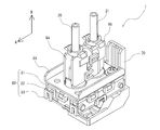
- FIG. 4 is a schematic view (perspective view) of the diaphragm pump 1 according to the present embodiment
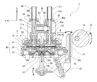
- FIG. 5 is a cross-sectional view of the diaphragm pump 1.
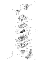
- FIG. 6 is an exploded view (perspective view) of the diaphragm pump 1.
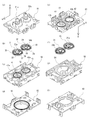
- FIG. 7 is an exploded view of the main components of the diaphragm pump 1 shown in a top side perspective view and a bottom side perspective view (that is, a perspective view in which the bottom side is reversed and shown as the top surface). More specifically, FIG. 7A is a top perspective view of the first housing part 81, and FIG. 7E is a bottom perspective view thereof. FIG. 7B is a top perspective view of the suction valve body 31 and the discharge valve body 32, and FIG. 7F is a bottom perspective view thereof. FIG. 7C is a top perspective view of the second housing part 82, and FIG. 7G is a bottom perspective view thereof. FIG. 7D is a top perspective view of the third housing part 83, and FIG. 7H is a bottom perspective view thereof.
- valve boxes 41 and 42 are configured in a state where the surface appearing in FIG. 7C and the surface appearing in FIG. 7E face each other.
- the working chamber 54 is configured in a state where the surface appearing in FIG. 7D and the surface appearing in FIG. 7G face each other.
- FIG. 8 is an enlarged view of the suction valve body 31 and the discharge valve body 32.
- FIG. 8A is a top perspective view
- FIG. 8B is a bottom perspective view.
- the height direction of the housing 80 in the direction of the arrow in FIGS. 4 to 8, the radial direction (arrow A), and the thickness direction (arrow B) of the intake valve body 31 and the discharge valve body 32.
- the circumferential direction arrow C. Note that the thickness direction of the suction valve body 31 and the discharge valve body 32 coincides with the height direction of the housing 80.
- the diaphragm pump 1 includes a working chamber 54 that is partially partitioned from the outside by a diaphragm 56, both of which communicate with the outside.
- a housing 80 having a suction passage 51 and a discharge passage 52 is provided.
- the ink tube 20 communicating with the ink tank 18 is connected to the inlet 51a at the end of the suction passage 51 via a bypass passage constituting member 84 described later.
- the ink tube 21 communicating with the recording head 25 is connected to the outlet 52 a at the end of the ejection path 52 via a bypass channel constituting member 85 described later.
- the bypass flow path components 84 and 85 are not essential components.
- the diaphragm 56 is driven to reciprocate to change the pressure in the working chamber 54 (depressurization / pressurization), thereby generating a liquid feeding action in the ink flow path.
- the ink flow path is provided with a one-way valve (diaphragm valves 3 and 4), which will be described later, so that liquid can be fed only in a predetermined direction (direction from the inlet 51a toward the outlet 52a). It is like that.
- the diaphragm valves 3 and 4 are required to respond to a small differential pressure.
- the front and back of the valve bodies 31 and 32 are moved with the movement (in and out) of a small amount of ink accompanying the volume change of the working chamber 54 (positioned on the upper side across the valve bodies 31 and 32 in FIG. 5). Since a small differential pressure is generated in the space and the space located below, it is required to respond to this small differential pressure.
- the diaphragm valve (hereinafter referred to as “suction valve”) 3 is a one-way valve (check valve) that allows ink to pass only from the suction path 51 toward the working chamber 54. It is.
- the diaphragm valve (hereinafter referred to as “discharge valve”) 4 is a one-way valve (check valve) that functions to allow ink to pass only from the working chamber 54 toward the discharge path 52.
- a valve body (hereinafter referred to as “suction valve body”) 31 is held by a valve box (hereinafter referred to as “suction valve body”) 41 formed in the housing 80, and the suction valve 3 A configuration is provided in which a valve seat portion (hereinafter referred to as “suction valve seat portion”) 61 of the suction valve body 31 is provided at a predetermined position in the box 41.
- suction valve seat portion a valve seat portion of the suction valve body 31 is provided at a predetermined position in the box 41.
- the discharge valve 4 has a valve body (hereinafter referred to as “discharge valve body”) 32 held in a valve box (hereinafter referred to as “discharge valve box”) 42 formed in the housing 80, and the discharge valve box 42.
- the valve seat portion (hereinafter referred to as “discharge valve seat portion”) 62 of the discharge valve body 32 is provided at a predetermined position. According to this, the close / communicating action of the flow path from the working chamber 54 to the discharge path 52 occurs due to the close contact / separation between the discharge valve body 32 and the discharge valve seat 62 (details will be described later).
- the liquid feeding action of the diaphragm pump 1 will be described.
- the diaphragm 56 When the diaphragm 56 is displaced toward the outside of the working chamber 54 (downward in FIG. 5), the volume in the working chamber 54 increases, and as a result, the pressure in the working chamber 54 is reduced. Then, the suction valve 3 communicates with the pressure difference of the ink to connect the flow path, and the discharge valve 4 closes the flow path. Therefore, the liquid (ink) in the ink tube 20 connected to the inflow port 51 a via the bypass flow path constituting member 84 is sucked into the working chamber 54 through the suction path 51.
- the diaphragm 56 is formed so as to be elastically deformable using an elastic material such as an elastomer (EPDM: ethylene-propylene-diene-methylene). Accordingly, the diaphragm 56 can be driven to reciprocate while the diaphragm 56 is deformed while maintaining the state where the outside and the working chamber 54 are partitioned by the diaphragm 56.
- EPDM ethylene-propylene-diene-methylene
- the diaphragm pump 1 includes an operating rod 58 that reciprocally drives the diaphragm 56.
- the operating rod 58 has one end 58a fixed to the diaphragm 56 by insert molding, and the other end 58b is pivoted with respect to a swing arm 70 (see FIG. 5) provided so as to be swingable. Connected as possible.
- Reference numeral 70a indicates a swing fulcrum.
- the intake valve body 31 and the discharge valve body 32 have a flat disk shape that is substantially circular in plan view.
- the direction of the radius in plan view is hereinafter referred to as the radial direction, and the axial direction of the disk is hereinafter referred to as the thickness direction.
- the suction valve body 31 is opposed to the center portion 33 provided with a seat portion 33a that is in close contact with and separated from the suction valve seat portion 61 at the radial center and the height direction of the suction valve box 41.
- the outer peripheral portion 35 sandwiched between the two surfaces 41 a and 41 b and the intermediate portion 37 that connects the central portion 33 and the outer peripheral portion 35 are configured.
- the intermediate part 37 is formed in a radial shape such as a spoke shape.
- the shape is not limited to this, and any shape having holes that allow ink to pass therethrough may be used.
- the discharge valve body 32 includes a central portion 34 provided with a seat portion 34a that is in close contact with and spaced from the discharge valve seat portion 62 at the radial center, and a height direction of the discharge valve box 42. It has the structure which has the outer peripheral part 36 clamped by the two surfaces 42a and 42b which oppose, and the spoke-shaped intermediate part 38 which connects the center part 34 and the outer peripheral part 36. As shown in FIG.
- the shape of the intermediate portion 38 is, for example, a radial shape such as a spoke shape.
- the shape is not limited to this, and any shape having holes that allow ink to pass therethrough may be used.
- the suction valve body 31 is formed so that the thickness of the outer peripheral portion 35 (see FIG. 8) is larger than the corresponding height direction dimension of the suction valve box 41 and is compressed in the thickness direction to the suction valve box 41. Is retained. Further, the discharge valve body 32 is formed such that the thickness of the outer peripheral portion 36 (see FIG. 8) is larger than the corresponding height direction dimension of the discharge valve box 42 and is compressed in the thickness direction. 42.
- the intake valve bodies 31 and 32 that is, the outer peripheral portions 35 and 36, the central portions 33 and 34, and the intermediate portions 37 and 38 are integrally formed using an elastic material such as an elastomer (EPDM) so as to be elastically deformable. And sufficient flexibility (easily deformable).
- EPDM elastomer
- the suction valve body 31 and the discharge valve body 32 have a configuration in which the outer peripheral portions 35 and 36 are held in a compressed state by the suction valve box 41 and the discharge valve box 42, respectively, and pass through the holes 39 and 40. It is possible to seal the ink to be prevented from leaking outside the outer peripheral portions 35 and 36. Further, the intermediate portions 37 and 38 can be elastically deformed, and the central portions 33 and 34 (sitting portions 33a and 34a) connected to the intermediate portions 37 and 38 can be caused to respond by the differential pressure of the ink. And can be brought into close contact with and separated from the valve seats 61 and 62, respectively.
- the flow path is sealed by the outer peripheral portion 35 of the suction valve body 31 and the outer peripheral portion 36 of the discharge valve body 32. That is, in the suction valve body 31, when ink passes through the hole 39 of the intermediate portion 37, it is possible to prevent the ink from leaking outside in the radial direction from the outer peripheral portion 35. Further, when the ink passes through the hole 40 of the intermediate portion 38 in the discharge valve body 32, it is possible to prevent the ink from leaking to the outside in the radial direction from the outer peripheral portion 36.
- the outer peripheral portion 35 of the suction valve body 31 and the outer peripheral portion 36 of the discharge valve body 32 in a compressed state have an outer diameter and a smaller inner diameter compared to the uncompressed state. Therefore, when the inner diameters of the outer peripheral portions 35 and 36 are reduced, the intermediate portions 37 and 38 continuing to the outer peripheral portions 35 and 36 are pushed from the outer side (outer edge side) in the radial direction toward the inner side (center side). In addition, the intermediate portions 37, 38 push the central portions 33, 34 continuous to the intermediate portions 37, 38.
- the central portion 33 which is originally set parallel to the radial direction, This may cause deformation such that the arrangement of the seating portions 33a and 34a of the 34 is inclined or the surface of the seating portions 33a and 34a formed in a flat shape is curved.
- the seating portion 33a and 34a are essentially in close contact with the suction valve seat portion 61 and the discharge valve seat portion 62, respectively, and the flow path should be closed. , 34a cannot be brought into close contact with the intake valve seat 61 and the discharge valve seat 62, respectively. That is, in the intake valve 3 and the discharge valve 4, poor closing occurs, and the valve cannot function as a one-way valve.
- the poor closing of the suction valve 3 and the discharge valve 4 is the reverse flow of the ink in the ink flow path, that is, the passage of the ink from the working chamber 54 to the suction path 51 in the suction valve body 31, which should normally be stopped. As a result, the ink passes from the discharge path 52 to the working chamber 54 in the discharge valve body 32.
- the intermediate portions 37 and 38 in each of the intake valve body 31 and the discharge valve body 32 are cross sections cut along a plane parallel to the radial direction and parallel to the thickness direction.
- the configuration is such that the shape is formed into a shape having one or a plurality of curved portions (or bent portions) 37a, 38a.
- FIG. 9 shows the sectional shape, that is, a sectional view taken along line IX-IX in FIG.
- a curved portion it may be formed in a S-shaped cross section, and in the case of a bent portion, it may be formed in a Z-shaped cross section.
- the curved portions (or bent portions) 37a and 38a are easily formed.
- An effect of deforming is obtained. That is, even if the intermediate portions 37 and 38 are pushed inward by the outer peripheral portions 35 and 36, the curved portions (or bent portions) 37 a and 38 a are deformed, so that the intermediate portions 37 and 38 push the center portions 33 and 34. It is possible to reduce the force to move.
- the intermediate portions 37 and 38 that is, the curved portions (or bent portions) 37a and 38a
- the central portions 33 and 34 seat portions 33a and 34a to be supported can operate in response to a small differential pressure of ink. Therefore, it is possible to realize a valve body suitable for transferring a very small amount of ink.
- the suction valve body 31 has a plurality of protrusions 35b that are provided on the outer peripheral surface 35a of the outer peripheral portion 35 in a radial direction, and has a radius from the center to the outer peripheral surface 35a of the outer peripheral portion 35. It is smaller than the corresponding radial dimension of the intake valve box 41, and the radius from the center to the tip surface of each projection 35 b is formed to be the same as the corresponding radial dimension of the intake valve box 41.
- the discharge valve body 32 has a plurality of protrusions 36b projecting radially on the outer peripheral surface 36a of the outer peripheral portion 36, and the radius from the center to the outer peripheral surface 36a of the outer peripheral portion 36 is It is smaller than the corresponding radial dimension of the discharge valve box 42, and the radius from the center to the tip surface of each projection 36 b is formed to be the same as the corresponding radial dimension of the discharge valve box 42.
- the suction valve body 31 has a radius from the center to the outer peripheral surface 35a of the outer peripheral portion 35 smaller than the corresponding radial dimension of the suction valve box 41, and the discharge valve body 32 has the outer peripheral portion 36 from the center. Since the radius to the outer peripheral surface 36a is smaller than the corresponding radial dimension of the discharge valve box 42, the outer peripheral portion 35 of the suction valve body 31 and the outer peripheral portion 36 of the discharge valve body 32 are compressed and removed. When the diameter increases, the outer peripheral portions 35 and 36 are deformed from the radially inner side (center side) to the outer side (outer edge side) in the suction valve box 41 and the discharge valve box 42, respectively. Is possible. Therefore, it is possible to reduce the amount of deformation of the outer peripheral portions 35 and 36 from the radially outer side (outer edge side) toward the inner side (center side).
- the outer peripheral portion compressed in the thickness direction as compared with the configuration in which the radius from the center to the outer peripheral surface of the outer peripheral portion is the same as the corresponding radial dimension of the valve box as in the conventional valve body Since the volumes of 35 and 36 can be reduced, as a result, the amount of deformation of the outer peripheral portions 35 and 36 from the radially outer side (outer edge side) toward the inner side (center side) can be reduced.
- the intake valve body 31 and the discharge valve body 32 have a plurality of projecting portions 35b and 36b projecting radially on the outer peripheral surfaces 35a and 36a of the outer peripheral portions 35 and 36, respectively, and The radii from the center to the tip surfaces of the protrusions 35b and 36b are formed to be the same as the corresponding radial dimensions of the suction valve box 41 and the discharge valve box 42, respectively.
- the discharge valve body 32 is fitted into the intake valve box 41 and the discharge valve box 42, respectively, the central position of the intake valve body 31 and the suction are not required in the radial direction without requiring a special positioning jig.
- the center position of the valve box 41 can be matched, and the center position of the discharge valve body 32 and the center position of the discharge valve box 42 can be matched in the radial direction.
- the central portions 33 and 34 of the suction valve body 31 and the discharge valve body 32 and the corresponding suction valve seat portions 61 and the discharge valve seat portions 62 are in a state where the center positions coincide with each other and there is no deviation in the radial direction. Since it can be arranged accurately, it is possible to prevent the backflow of ink due to the positional deviation between the central portions 33 and 34 and the suction valve seat portion 61 and the discharge valve seat portion 62. Therefore, it is possible to reliably prevent the passage of ink in the direction from the working chamber 54 to the suction path 51 in the suction valve body 31 and the passage of ink in the direction from the discharge path 52 to the working chamber 54 in the discharge valve body 32. It becomes.
- center portions 33 and 34 of the suction valve body 31 and the discharge valve body 32 can be easily aligned with the corresponding suction valve seat portion 61 and discharge valve seat portion 62 without using a special positioning jig. Therefore, it is possible to simplify both the manufacturing equipment and the manufacturing process.
- suction valve body 31 and the discharge valve body 32 are arranged around the other surfaces of the central portions 33 and 34, that is, the surfaces 33b and 34b opposite to the seating portions 33a and 34a in the thickness direction. It has a configuration having a plurality of projecting portions 33c and 34c projecting in the thickness direction so as to be discontinuous in the direction.
- the surface 33 b on the other surface side of the central portion 33 faces the suction valve seat portion 61 in the suction valve box 41 when ink is passed in the direction from the suction passage 51 toward the working chamber 54. There is a risk that the flow will be blocked by abutting against the surface to be cut.
- the plurality of protrusions 33c provided on the opposite surface 33b abuts on the surface of the intake valve box 41 that faces the intake valve seat portion 61. It is possible to prevent the entire side surface 33b from being in close contact with each other and block the flow path, and it is possible to ensure the flow of ink in the originally permitted direction.
- the surface 34 b on the other surface side of the center portion 34 is formed by the discharge valve seat portion in the discharge valve box 42.
- the plurality of protrusions 34c provided on the opposite surface 34b come into contact with the surface facing the discharge valve seat 62 in the discharge valve box 42, thereby It is possible to prevent the entire side surface 34b from coming into close contact and block the flow path, and it is possible to ensure the flow of ink in the originally permitted direction.
- the housing 80 of the diaphragm pump 1 is configured by connecting a plurality of housings. More specifically, as shown in FIGS. 5 to 7, the first housing part 81, the second housing part 82, and the third housing part 83 are connected in order from the top in the height direction (arrow B direction). ing.
- the plurality of housings is not limited to three cases.
- a part of the suction valve box 41 is formed on the lower surface of the first housing part 81 and the remaining part is formed on the upper surface of the second housing part 82, and is configured as a space having a predetermined shape.
- a part of the discharge valve box 42 is formed on the lower surface of the first housing part 81, and the remaining part is formed on the upper surface of the second housing part 82.
- the discharge valve box 42 is configured as a space having a predetermined shape.
- the working chamber 54 is partly formed on the lower surface of the second housing part 82 and formed on the upper surface of the remaining third housing part 83, and is configured as a space having a predetermined shape.
- bypass flow path constituting members 84 and 85 are moved from the bypass flow path constituting member 85 connected to the discharge path 52 to the bypass flow path constituting member 84 connected to the suction path 51 with a pressure valve 88 (biased with the ball 86).
- the bypass flow path is configured through a pressure valve that is configured using the member 87 and closes below a predetermined pressure and opens above a predetermined pressure.
- the diaphragm pump 1 may have a configuration in which the bypass flow path components 84 and 85 and the pressure valve 88 are not provided. Therefore, the bypass flow path components 84 and 85 and the pressure valve 88 are formed separately from the housing 80 and can be attached to and detached from the housing 80 (here, the first housing part 81) as necessary. It has a simple structure. As a result, replacement is facilitated, so that it is easy to cope with a malfunction and change the valve opening pressure. In the case where the bypass flow path components 84 and 85 and the pressure valve 88 are not provided, the ink tubes 20 and 21 are directly connected to the inlet 51a and the outlet 52a, respectively.
- the housing 80 has a divided structure including the first housing part 81, the second housing part 82, and the third housing part 83, the first housing part 81 and the second housing part 82 are divided as described above.
- the suction valve box 41 and the discharge valve box 42 can be easily formed, and the working chamber 54 can be easily formed by the second housing part 82 and the third housing part 83. That is, the housing 80 can be easily formed without requiring a complicated mold or a complicated processing step.
- outer peripheral portion 35 of the intake valve body 31 and the outer peripheral portion 36 of the discharge valve body 32 can be used as a sealing material for the connecting portion between the first housing part 81 and the second housing part 82, the structure and method of the seal are simplified. And it can be made easy.
- connection between the first housing part 81 and the second housing part 82 and the connection between the second housing part 82 and the third housing part 83 are connected by snap-fit engagement. More specifically, as shown in FIG. 6, reference numeral 81a is a snap-fit engagement recess, and reference numeral 82a is a snap-fit engagement protrusion engaged therewith. Reference numeral 83a denotes a snap-fit engagement concave portion, and reference numeral 82b denotes a snap-fit engagement convex portion engaged therewith.
- the first housing part 81, the second housing part 82, and the third housing part 83 formed as a divided structure can be connected by a very simple engagement process.
- the number of parts can be reduced.
- an auxiliary fixing member 89 that performs screw fastening is further provided to further strengthen the first housing part 81, the second housing part 82, and the third housing part 83 that are connected to each other. It is set as the structure which can be fixed and can ensure the seal of a connection part. However, the auxiliary fixing member 89 may not be provided.
- liquid feeding unit 2 that includes the diaphragm pump 1 according to the present embodiment and that feeds liquid (here, ink) will be described.
- liquid here, ink
- FIG. 10 the apparatus block diagram of the liquid feeding unit 2 is shown.
- the case where there are four ink colors will be described as an example, but the present invention is not limited to this.
- the liquid feeding unit 2 includes a diaphragm pump 1 (1A to 1D) disposed for performing liquid feeding for each ink color, and a swing arm 70 (70A to 70D) of each diaphragm pump 1 (1A to 1D).
- An eccentric cam 72 (72A to 72D) serving as a drive member for swinging is configured.
- Each eccentric cam 72 (72A to 72D) is fixed to one rotating shaft 74 with a phase different from each other, and is configured to be rotationally driven simultaneously by the rotation of the rotating shaft 74. In this configuration, it is necessary to provide bypass flow path components 84 and 85 and a pressure valve 88.
- the swing arm 70 of the diaphragm pump 1 is disposed so that one end of the operating rod 58 is connected to one end, and the cam surface of an eccentric cam 72 rotatably provided to the other end. (See FIG. 5).
- the swing arm 70 is pushed by the cam surface, and the swing arm 70 is pulled by the urging member 92.
- the swing arm 70 disposed in contact with the cam surface of the eccentric cam 72 can be swung. Therefore, since the operating rod 58 connected to the swing arm 70 can be reciprocated, the diaphragm 56 connected (fixed) to the operating rod 58 can be driven reciprocally, and ink is sucked as described above. -It is possible to generate a driving force to be discharged.
- the liquid feeding unit 2 is an electromagnetic that opens and closes the flow path downstream of the discharge valve body 32 (in the present embodiment, in the middle of the ink tubes 21 (21A to 21D)).
- a valve 76 (76A to 76D) is provided.
- the eccentric cam 72 (72A to 72D) is always driven to rotate, that is, the swing arm 70 (70A to 70D), the operating rod 58, and the diaphragm 56 are always driven to reciprocate.
- the electromagnetic valve 76 (76A to 76D) as necessary, the liquid feeding from the discharge passage 52 can be executed / stopped. Accordingly, it is possible to feed a necessary amount of ink when necessary.
- the bypass flow path component member 85 connected to the suction path 51 is provided with a pressure valve 88 from the bypass flow path component member 85 connected to the discharge path 52.
- the pressure valve 88 is opened to form a bypass flow path. That is, the pressure valve 88 functions as a relief valve.
- the discharge-side flow path (the flow path of the ink tube 21) is closed, the working chamber 54 remains filled with ink. 72D) does not act on the swing arm 70 (70A to 70D). Therefore, even when the bypass flow path components 84 and 85 and the pressure valve 88 are not arranged, there is a feature that the possibility that the liquid pressure becomes excessive and damage (liquid leakage) occurs in the flow path is small.
- the configuration of the drive mechanism for rotationally driving the eccentric cam 72 (72A to 72D) can be simplified, and the drive control method for the rotational drive can be simplified. can do.
- FIG. 11 the apparatus block diagram of the modification of the liquid feeding unit 2 is shown.
- the liquid feeding unit 2 has rotational power between an eccentric cam 72 (72A to 72D) and a rotary shaft 74 that rotationally drives the eccentric cam 72 (72A to 72D).
- An electromagnetic clutch 78 (78A to 78D) that performs transmission and disconnection is provided.
- the bypass flow path components 84 and 85 and the pressure valve 88 can be omitted.
- the eccentric cam 72 (72A to 72D) can be rotated and stopped by transmitting and disconnecting the rotational power by the electromagnetic clutch 78 (78A to 78D) as necessary, and the discharge path. It becomes possible to execute and stop the liquid feeding from 52. Accordingly, it is possible to feed a necessary amount of ink when necessary.
- the eccentric cam 72 since it is not necessary to always rotate the eccentric cam 72 (72A to 72D), wear at the sliding portion can be reduced and the life of the apparatus can be extended. Further, the configuration in which the electromagnetic valve 76 for opening and closing the flow path is provided on the downstream side of the discharge valve body 32 as in the example shown in FIG. 10 described above is unnecessary, and the bypass flow path component members 84 and 85 and the pressure valve are further provided. The structure which provides 88 becomes unnecessary. Therefore, the installation space can be reduced, and the size of the apparatus can be reduced.
- the pressure in the working chamber 54 changes.
- the pressure in the working chamber 54 is reduced, and liquid (ink) is sucked into the working chamber 54 from the suction path 51.
- An effect occurs.
- the pressure in the working chamber 54 is increased, and the action of discharging liquid (ink) from the working chamber 54 to the discharge path 52 is achieved.
- the hydraulic pressure acting on the seating portion 33a of the central portion 33 is higher than the hydraulic pressure acting on the opposite surface 33b.
- the seating portion 33a and the suction valve seat portion 61 are separated from each other, and ink flow is performed.
- the hydraulic pressure acting on the seat 34a of the central portion 34 is lower than the hydraulic pressure acting on the opposite surface 34b, so that the seat 34a and the discharge valve seat 62
- the ink flow is blocked by close contact. In other words, it is possible to allow ink to flow only from the suction path 51 toward the working chamber 54, and to prevent backflow of ink in the direction from the discharge path 52 toward the working chamber 54.
- the hydraulic pressure acting on the seat 34 a of the central portion 34 is greater than the hydraulic pressure acting on the opposite surface 34 b.
- the seating portion 34a and the discharge valve seat portion 62 are separated from each other, and ink flow is performed.
- the hydraulic pressure acting on the seat 33a of the central portion 33 is lower than the hydraulic pressure acting on the opposite surface 33b, so that the seat 33a and the suction valve seat 61
- the ink flow is blocked by close contact. That is, it is possible to allow ink to flow only from the working chamber 54 toward the discharge path 52 and to prevent backflow of ink in the direction from the working chamber 54 toward the suction path 51.
- a possible diaphragm valve body, the diaphragm valve, a diaphragm pump using the diaphragm valve, and a liquid feeding unit can be realized.
- the valve bodies 31 and 32 of this embodiment are the valve bodies of the diaphragm valves 3 and 4 that allow fluid to pass only in a predetermined direction in the flow path, and are compressed in the thickness direction to be the valve boxes of the diaphragm valves 3 and 4.
- the outer peripheral portions 35 and 36 held by the pins 41 and 42 and the seating whose one surface side is in close contact with and separated from the valve seat portions 61 and 62 of the valve boxes 41 and 42 by elastic displacement in the thickness direction in response to the differential pressure of the fluid.
- Intermediate portions 37 and 38 having hole portions 39 and 40 through which the fluid can pass through the central portions 33 and 34 provided with the portions 33a and 34a, and between the outer peripheral portions 35 and 36 and the central portions 33 and 34.
- intermediate portions 37 and 38 have one or a plurality of curved portions (or bent portions) 37a and 38a in a cross-sectional shape when cut along a plane parallel to the radial direction and parallel to the thickness direction. It is formed in the shape which has this.
- the intermediate portions 37 and 38 having the curved portions (or bent portions) 37a and 38a of the valve bodies 31 and 32 are configured as easily deformable portions. That is, when the outer peripheral portions 35, 36 are compressed and the intermediate portions 37, 38 are pushed inward from the outside in the radial direction, the curved portions (or bent portions) 37a, 38a are easily deformed, It is possible to reduce the force by which the intermediate portions 37 and 38 push and move the central portions 33 and 34. Therefore, it is possible to prevent deformation such as the arrangement of the central portions 33 and 34 being inclined, and the seating portions 33a and 34a and the valve seat portions 61 and 62 can be reliably adhered. Therefore, it becomes possible to reliably prevent poor closing. Further, since the intermediate portions 37 and 38 can be easily deformed, the central portions 33 and 34 (sitting portions 33a and 34a) can be operated in response to a small differential pressure of ink to be fed. Become.
- the outer peripheral portions 35 and 36 have a plurality of projecting portions 33c and 34c projecting radially from the outer peripheral surfaces 35a and 36a.
- the outer peripheral portions 35 and 36 of the discharge valve body 32 are compressed and the outer diameter is increased, respectively, in the intake valve box 41 and the discharge valve box 42, respectively.
- the outer peripheral portions 35 and 36 can be deformed from the radially inner side (center side) to the outer side (outer edge side). Therefore, it is possible to reduce the amount of deformation of the outer peripheral portions 35 and 36 from the radially outer side (outer edge side) toward the inner side (center side).
- the volume of the outer peripheral portions 35 and 36 to be compressed can be reduced, the outer peripheral portions 35 and 36 are deformed from the outer side (outer edge side) in the radial direction toward the inner side (center side). The amount of deformation to be reduced can be reduced.
- the central portions 33 and 34 have a plurality of protrusions 35b and 36b that protrude in the thickness direction so as to be discontinuous in the circumferential direction on the other surface side of the seating portions 33a and 34a. It is preferable.
- the surfaces 33b and 34b on the other surface side (opposite side in the thickness direction) with respect to the seating portions 33a and 34a of the central portions 33 and 34 are surfaces facing the valve seat portions 61 and 62 in the valve boxes 41 and 42, respectively. There may be a case of abutting against.
- the plurality of protrusions 33c and 34c provided on the opposite surfaces 33b and 34b come into contact with the surface facing the valve seats 61 and 62, so that the surfaces 33b and 34b are in close contact with each other. It is possible to prevent the flow path from being blocked, and it is possible to ensure the flow of ink in the direction that should be allowed.
- the outer peripheral portions 35 and 36, the central portions 33 and 34, and the intermediate portions 37 and 38 are preferably integrally formed using an elastic material such as an elastomer.
- the valve bodies 31 and 32 have a configuration in which the outer peripheral portions 35 and 36 are held in a compressed state by the suction valve box 41 and the discharge valve box 42, respectively, and the ink passing through the hole portions 39 and 40 is It can seal so that it may not leak to the outer side of the parts 35 and 36.
- the intermediate portions 37 and 38 can be elastically deformed, and the central portions 33 and 34 (sitting portions 33a and 34a) connected to the outer peripheral portions 35 and 36 through the intermediate portions 37 and 38 are ink-filled. It can be made to respond by the pressure difference between the valve seat portions 61 and 62, and can be brought into close contact with or separated from each other. Moreover, since it is integral molding, manufacture becomes easy.
- the diaphragm valves 3 and 4 of the present embodiment each include an inflow port 51a and an outflow port 52a that open to the outside, and a housing 80 in which a flow path that connects the inflow port 51a and the outflow port 52a is formed.
- the valve bodies 31, 32 disposed in the flow path, and valve seat parts 61, 62 provided at positions facing the seats 33a, 34a of the valve bodies 31, 32 in the flow path,
- the valve bodies 31, 32 are elastically displaced, and the seat portions 33a, 34a are brought into close contact with and separated from the valve seat portions 61, 62.
- the flow path is closed and communicated, and the ink is allowed to pass only from the inflow port 51a toward the outflow port 52a.
- valve bodies 31 and 32 are elastically displaced in response to a small differential pressure of ink, and the seat portions 33a and 34a are in close contact with and separated from the valve seat portions 61 and 62, respectively, thereby closing and communicating the flow path.
- a diaphragm valve can be realized. Further, the backflow of ink can be reliably prevented by the valve bodies 31 and 32. Therefore, it can be prevented that a predetermined amount of ink is not fed due to poor closing of the diaphragm valve.
- the diaphragm pump 1 of the present embodiment includes a diaphragm 56 that is elastically displaceable in the thickness direction, a working chamber 54 that is partly partitioned from the outside by the diaphragm 56, and both the working chamber 54 and the outside.
- a housing 80 having a suction path 51 and a discharge path 52 that communicate with each other, a suction valve 3 that allows fluid to pass only from the suction path 51 toward the working chamber 54, and only from the working chamber 54 toward the discharge path 52.
- a discharge valve 4 that allows fluid to pass through.
- the suction valve 3 and the discharge valve 4 use the diaphragm valve described above, and the diaphragm 56 is driven to reciprocate to pass through the suction path 51 from the outside to actuate the working chamber 54. Ink is sucked into the ink, and ink is ejected from the working chamber 54 through the ejection path 52 to the outside.
- a diaphragm pump can be realized in which ink is fed only toward the path 52 to reliably prevent backflow.
- the diaphragm pump is a metering pump, it is possible to prevent the amount of liquid being fed from being lost by preventing the backflow described above.
- an operating rod 58 for reciprocatingly driving the diaphragm 56, and the operating rod 58 is preferably insert-molded at the one end portion 58a.
- the operating rod may fall out of the diaphragm due to deterioration over time.
- the fixing structure of the diaphragm 56 and the operating rod 58 can be further strengthened, so that the operating rod 58 can be prevented from coming off from the diaphragm 56 for a long time.
- the operating rod 58 is connected to a swing arm 70 whose other end portion 58b is swingably provided, and the swing arm 70 swings to reciprocate the operating rod 58. Accordingly, it is preferable that the diaphragm 56 is reciprocated in the thickness direction.
- the operating rod 58 connected to the swing arm 70 can be reciprocated by swinging the swing arm 70. Accordingly, the diaphragm 56 connected to the operating rod 58, that is, fixed by insert molding, can be driven back and forth, and a driving force for sucking ink into the working chamber 54 and discharging it out of the working chamber 54 can be generated. It becomes.
- the housing 80 is preferably formed by connecting a plurality of housings (here, the first housing part 81, the second housing part 82, and the third housing part 83).
- the plurality of housings (here, the first housing part 81, the second housing part 82, and the third housing part 83) are connected to each other by snap-fit engagement.
- a plurality of housings (here, the first housing part 81, the second housing part 82, and the third housing part 83) can be coupled by a very simple process. Further, compared to a configuration in which each housing is fixed by screwing, screws and bolts are not required, and the number of parts can be reduced.
- the liquid feeding unit 2 of the present embodiment includes a plurality of eccentric cams 72 arranged on one rotary shaft 74 with phases different from each other, and the swing arm 70 is driven by each eccentric cam 72.
- a plurality of diaphragm pumps 1 are provided.
- each swing arm 70 disposed in contact with the cam surface of each eccentric cam 72 is provided. It can be swung. Therefore, since each operating rod 58 connected to each swing arm 70 can be reciprocated, each diaphragm 56 connected (fixed) to each operating rod 58 can be driven back and forth, and each diaphragm can be driven.
- the pump 1 can generate a driving force for sucking and discharging ink.
- each diaphragm pump 1 is preferably provided with an electromagnetic valve 76 that is simultaneously driven by each eccentric cam 72 and closes / communicates the flow path downstream of the discharge valve 4.
- the eccentric cams 72 are always driven to rotate, that is, the rocking arms 70, the operating rods 58, and the diaphragms 56 are always reciprocatingly driven as necessary.
- each electromagnetic valve 76 it becomes possible to execute and stop liquid feeding from the discharge passage 52.
- an electromagnetic clutch 78 for transmitting / disconnecting rotational power is provided between the rotating shaft 74 and each eccentric cam 72.
- the eccentric cam 72 can be rotated / stopped by transmitting / disconnecting the rotational power by each electromagnetic clutch 78 as necessary, and liquid feeding from the discharge passage 52 is executed. ⁇ It becomes possible to stop. Therefore, a configuration without the electromagnetic valve 76 can be realized, and the device can be simplified and saved in space.
- the present invention is not limited to the embodiment described above, and various modifications can be made without departing from the present invention.
- a diaphragm pump in which a diaphragm valve having a valve body according to the present invention is incorporated is mounted on a liquid feeding unit 2 of an ink jet recording apparatus and applied as a liquid feeding apparatus, that is, an ink supply apparatus will be described as an example.
- the present invention is not limited to this, and can be applied to other apparatuses.
- the liquid to be fed is not limited to ink.
- Diaphragm pump Liquid feed unit 3
- Diaphragm valve (suction valve) 4
- Diaphragm valve (discharge valve) 10
- Inkjet recording device 18, 18A, 18B, 18C, 18D Ink tank 19 Connection portion 20, 20A, 20B, 20C, 20D Ink tube 21, 21A, 21B, 21C, 21D Ink tube 23
- Head unit 24 Carriage 25, 25A, 25B , 25C, 25D Recording head (inkjet head)
- Valve body (suction valve body) 32
- Valve body (Discharge valve body) 33, 34 Center part 33a, 34a Seating part 33c, 34c Protrusion part 35, 36 Outer peripheral part 35b, 36b Protrusion part 37, 38 Intermediate part 37a, 38a Curved part (bent part) 39, 40 Hole 41 Valve box (suction valve box) 42
- Valve box (discharge valve box) 51 Suction path 51a Inlet 52 Discharge path 52a Outlet 54
Landscapes
- Engineering & Computer Science (AREA)
- General Engineering & Computer Science (AREA)
- Mechanical Engineering (AREA)
- Reciprocating Pumps (AREA)
- Details Of Reciprocating Pumps (AREA)
Abstract
液体の非常に小さな差圧にも応動可能で、且つ、流路の閉鎖不良を防止して液体の逆止を確実に行うことを可能とする、流路における所定の方向にのみ流体を通過させるダイヤフラム弁(3、4)の弁体(31、32)であって、厚さ方向に圧縮されてダイヤフラム弁(3、4)の弁箱(41、42)に保持される外周部(35、36)と、流体の差圧に応動して厚さ方向に弾性変位して弁箱(41、42)の弁座部(61、62)に一面側が密着・離間する着座部(33a、34a)が設けられた中心部(33、34)と、外周部 (35、36)と中心部(33、34)との間に配されて流体が通過可能な孔部(39、40)を有する中間部(37、38)と、を備え、中間部(37、38)は、径方向と平行で且つ厚さ方向と平行な面で切断した場合の断面形状が、一つもしくは複数の湾曲部(もしくは折曲部)(37a、38a)を有する形状に形成されている。
Description
本発明は、インクに例示される液体の送液に好適に適用し得る弁体、ダイヤフラム弁、ダイヤフラムポンプ、および送液ユニットに関する。
インクジェットヘッドのノズルから液体(インク)を吐出して、記録媒体に所望の文字や図形を記録(印刷)するインクジェット記録装置(インクジェットプリンタ)について、従来より種々の構成のものが知られている。
一般に、インクジェット記録装置では、印刷の実施すなわちノズルからのインク吐出によって、インクジェットヘッドのインク供給室に貯留されたインクが次第に減少するため、当該インク供給室へインクを供給する必要が生じる。そこで、従来より、インクの供給に用いられるポンプに関する研究開発が行われている。
その他、様々な技術分野においても液体の送出を行うポンプに関する研究開発が行われており、例えば、特許文献1において自動車のエンジンに燃料を供給するための装置としてダイヤフラムを用いたフュエルポンプが開示されている。
本願発明者らは、インクジェット記録装置における送液装置(インク供給装置)として、液体(インク)の非常に小さな差圧にも応動し得るダイヤフラム弁を備えて、微少量のインク移送に好適なダイヤフラムポンプの研究開発に取り組んだ。
当該ダイヤフラムポンプにおいては、液体(インク)の非常に小さな差圧にも応動し、且つ、流路の閉鎖不良を確実に防止し得るダイヤフラム弁の実現が課題となっていた。
本発明は、上記課題に鑑みてなされたものであり、液体(インク)の非常に小さな差圧にも応動可能で、且つ、流路の閉鎖不良を防止して液体(インク)の逆止を確実に行うことが可能なダイヤフラム弁の弁体、当該ダイヤフラム弁、およびこれを用いたダイヤフラムポンプ、送液ユニットを提供することを目的とする。
一実施形態として、以下に開示するような解決手段により、前記課題を解決する。
以下に開示される弁体は、流路における所定の方向にのみ流体を通過させるダイヤフラム弁の弁体であって、厚さ方向に圧縮されてダイヤフラム弁の弁箱に保持される外周部と、流体の差圧に応動して厚さ方向に弾性変位して前記弁箱の弁座部に一面側が密着・離間する着座部が設けられた中心部と、前記外周部と前記中心部との間に配されて流体が通過可能な孔部を有する中間部と、を備え、前記中間部は、径方向と平行で且つ厚さ方向と平行な面で切断した場合の断面形状が、一つもしくは複数の湾曲部もしくは折曲部を有する形状に形成されていることを特徴とする。
ダイヤフラムの厚さ方向に圧縮された(押し潰された)状態のダイヤフラム弁の弁体の外周部は、圧縮されていない状態と比較して、外径が大きくなり且つ内径が小さくなる。
従来のダイヤフラム弁の弁体では、外周部の内径が小さくなることによって、中間部が径方向の外側(外縁側)から内側(中心側)へ向かって押された状態となり、さらに、中間部が中心部を押し動かすこととなり、例えば、本来は径方向と平行に設定されている中心部の配置(特に着座部の配置)が、弁座部に対して斜めになって正対しない状態となってしまう等の変形を生じさせる原因となっていた。この変形によって、中心部の着座部の全周が弁座部に密着できない閉鎖不良を生じ、液体の逆止不良が発生することが研究により判明した。
従来のダイヤフラム弁の弁体では、外周部の内径が小さくなることによって、中間部が径方向の外側(外縁側)から内側(中心側)へ向かって押された状態となり、さらに、中間部が中心部を押し動かすこととなり、例えば、本来は径方向と平行に設定されている中心部の配置(特に着座部の配置)が、弁座部に対して斜めになって正対しない状態となってしまう等の変形を生じさせる原因となっていた。この変形によって、中心部の着座部の全周が弁座部に密着できない閉鎖不良を生じ、液体の逆止不良が発生することが研究により判明した。
これに対して、上記の弁体によれば、湾曲部もしくは折曲部を有する中間部が、径方向に容易に変形可能な部分として構成される。すなわち、外周部が圧縮されて中間部が径方向の外側から内側へ向かって押された際に、湾曲部もしくは折曲部が容易に変形して、中間部が中心部を押し動かす力を低減することが可能となる。したがって、中心部の配置が斜めになってしまう等の変形を生じることを防止することができ、着座部と弁座部との密着を確実に行うことができるため、閉鎖不良を確実に防止することが可能となる。また、中間部が容易に変形可能となることによって、中心部(着座部)は、液体の小さな差圧に応動して動作することが可能となる。
本発明によれば、液体の非常に小さな差圧にも応動可能で、且つ、流路の閉鎖不良を防止して液体の逆止を確実に行うことが可能なダイヤフラム弁の弁体、当該ダイヤフラム弁、およびこれを用いたダイヤフラムポンプ、送液ユニットが実現できる。
以下、図面を参照して、本発明の実施形態について詳しく説明する。
ここでは、本実施形態に係る弁体31、32を備えるダイヤフラム弁3、4が配設されたダイヤフラムポンプ1(図5参照)がインクジェット記録装置10の送液ユニット2に搭載されて、送液装置すなわちインク供給装置として適用される場合を例に挙げて説明を行う。
ただし、当該ダイヤフラムポンプ1はインクジェット記録装置以外にも搭載可能であって、インク以外の液体の送液に適用可能であることはもちろんである。
ここでは、本実施形態に係る弁体31、32を備えるダイヤフラム弁3、4が配設されたダイヤフラムポンプ1(図5参照)がインクジェット記録装置10の送液ユニット2に搭載されて、送液装置すなわちインク供給装置として適用される場合を例に挙げて説明を行う。
ただし、当該ダイヤフラムポンプ1はインクジェット記録装置以外にも搭載可能であって、インク以外の液体の送液に適用可能であることはもちろんである。
図1は、本実施形態に係るダイヤフラムポンプ1が搭載されるインクジェット記録装置10の概略図(斜視図)である。また、図2は、当該インクジェット記録装置10のヘッドユニット23周辺の概略図(斜視図)である。また、図3は、当該インクジェット記録装置10に搭載されるインクタンク18、ダイヤフラムポンプ1、および記録ヘッド25の装置構成を示す概略図である。
なお、説明の便宜上、各図において矢印方向で当該インクジェット記録装置10の前後、左右、および上下方向を示す。
また、実施形態を説明するための全図において、同一の機能を有する部材には同一の符号を付し、その繰り返しの説明は省略する場合がある。
なお、説明の便宜上、各図において矢印方向で当該インクジェット記録装置10の前後、左右、および上下方向を示す。
また、実施形態を説明するための全図において、同一の機能を有する部材には同一の符号を付し、その繰り返しの説明は省略する場合がある。
ここで、例えば特許文献1に例示される自動車用のダイヤフラムポンプを、インクジェット記録装置用のダイヤフラムポンプとしてそのまま利用することはできない。その理由として、自動車の燃料ポンプに燃料を供給するダイヤフラムポンプの場合には、なによりも堅牢性が重要となり、且つ、数kgf/cm2の吐出圧および百リットル/時以上の吐出量が要求されるのが通常であるからである。
これに対し、インクジェット記録装置においてインク供給にダイヤフラムポンプを用いる場合には、a)せいぜい数ミリリットル/ストローク程度の少量の液体を、b)1kgf/cm2よりもずっと小さな圧力(差圧)で吸入・吐出し、c)ある程度の定量性も有する、といった特性が求められる。本発明の発明者らは、これらの要求を満たすためにまず逆止弁(ダイヤフラム弁(吸入弁、吐出弁)3、4)の動作を確実ならしめる必要があることを見出し、その改良に取り組んだものである。具体的には、「微少量の液体(インク)の流動に応じて流路を開閉可能にするためダイヤフラム弁3、4の弁体31、32を柔軟に形成しなければならない」一方で、「そのようにすると歪の影響によって着座(閉鎖)不良を生じ易くなる」というトレードオフの問題の解決に取り組んだ。
先ず、インクジェット記録装置10について説明する。
本実施形態に係るインクジェット記録装置10は、紙、布、樹脂シート(例えば、塩化ビニル、ポリエステル等からなる)等の記録媒体Mの記録面(印刷面)に対して記録ヘッド(インクジェットヘッド)25のノズルから液体(ここでは、インク)を吐出することにより文字や図形等の印刷加工を行う装置である。なお、インクには、UV(紫外線)の照射によって硬化するUVインク、水性昇華転写インク等の水性インク、もしくはソルベントインク等の溶剤系インクといった種々のインクを用いることができる。
本実施形態に係るインクジェット記録装置10は、紙、布、樹脂シート(例えば、塩化ビニル、ポリエステル等からなる)等の記録媒体Mの記録面(印刷面)に対して記録ヘッド(インクジェットヘッド)25のノズルから液体(ここでは、インク)を吐出することにより文字や図形等の印刷加工を行う装置である。なお、インクには、UV(紫外線)の照射によって硬化するUVインク、水性昇華転写インク等の水性インク、もしくはソルベントインク等の溶剤系インクといった種々のインクを用いることができる。
本実施形態に係るインクジェット記録装置10は、図1、2に示すように、支持脚11により支持された中央ボディ部12と、中央ボディ部12の左側に設けられた左ボディ部13と、中央ボディ部12の右側に設けられた右ボディ部14と、左右ボディ部13、14を繋ぐとともに中央ボディ部12の上側に設けられた上ボディ部15とを備えて構成される。中央ボディ部12には、記録媒体Mが載置されるプラテン29が設けられており、当該プラテン29上に記録媒体Mを載置し、後述の記録ヘッド25からインクを吐出することによって、印刷が行われる。
左ボディ部13には、その前面側に操作スイッチ類や表示装置類が設けられ、その内部に後述するヘッドユニット23(図2参照)を左右に移動させるモータ、ベルト等からなる左右移動機構(不図示)、ヘッドユニット23の洗浄等を行うメンテナンスステーション(不図示)、および各構成部材の作動制御を行う制御手段としてのコントロールユニット28等が設けられている。
ここで、図2に示すように、上ボディ部15の内部には、左右に延びたガイドレール16が設けられ、このガイドレール16に対して左右に移動可能にヘッドユニット23が取り付けられている。このヘッドユニット23は、左右移動機構により駆動されて上ボディ部15の内部においてガイドレール16に沿って左右に往復移動されるようになっている。
ここで、ヘッドユニット23は、図2に示すように、記録ヘッド25、および当該記録ヘッド25を固定し且つガイドレール16に対する移動作用を担うキャリッジ24を主体に構成されている。なお、本実施形態に係る記録ヘッド25は、設定されるインクの色ごとに複数設けられている。
一例として、記録ヘッド25は、マゼンタ記録ヘッド25A、イエロー記録ヘッド25B、シアン記録ヘッド25C、ブラック記録ヘッド25Dを備えて構成されている。なお、各記録ヘッド25(25A~25D)の下面には、下方に載置される記録媒体Mに向けてインクを吐出する複数のノズル(不図示)が形成されている。
一例として、記録ヘッド25は、マゼンタ記録ヘッド25A、イエロー記録ヘッド25B、シアン記録ヘッド25C、ブラック記録ヘッド25Dを備えて構成されている。なお、各記録ヘッド25(25A~25D)の下面には、下方に載置される記録媒体Mに向けてインクを吐出する複数のノズル(不図示)が形成されている。
一方、図1に示すように、右ボディ部14の内部には、カートリッジ取付部17が設けられており、このカートリッジ取付部17に対して、インクが貯留されたカートリッジ式のインクタンク18が前面側から着脱可能に取り付けられている。
本実施形態においては、インクの色ごとに複数のインクタンクが設けられている。一例として、インクタンク18は、マゼンタインクタンク18A、イエローインクタンク18B、シアンインクタンク18C、ブラックインクタンク18Dを備えて構成されている(図3参照)。なお、インクタンク18(18A~18D)は、カートリッジ式に限定されるものではない。
本実施形態においては、インクの色ごとに複数のインクタンクが設けられている。一例として、インクタンク18は、マゼンタインクタンク18A、イエローインクタンク18B、シアンインクタンク18C、ブラックインクタンク18Dを備えて構成されている(図3参照)。なお、インクタンク18(18A~18D)は、カートリッジ式に限定されるものではない。
また、図3の構成図に示すように、カートリッジ取付部17の内部には、インクタンク18(18A~18D)を受容してインクを受け入れる接続部19(インクの色ごとに対応する接続部19A~19D)が設けられている。
そして、この接続部19(19A~19D)から、右ボディ部14および上ボディ部15の内部に設けられたインクチューブ20(インクの色ごとに対応するインクチューブ20A~20D)、およびインクチューブ21(インクの色ごとに対応するインクチューブ21A~21D)が色ごとに対応する記録ヘッド25(25A~25D)と繋がっており、インクタンク18(18A~18D)のインクがインクチューブ20(20A~20D)、21(21A~21D)を介して記録ヘッド25(25A~25D)内のインク供給室(不図示)に供給されるようになっている。
そして、この接続部19(19A~19D)から、右ボディ部14および上ボディ部15の内部に設けられたインクチューブ20(インクの色ごとに対応するインクチューブ20A~20D)、およびインクチューブ21(インクの色ごとに対応するインクチューブ21A~21D)が色ごとに対応する記録ヘッド25(25A~25D)と繋がっており、インクタンク18(18A~18D)のインクがインクチューブ20(20A~20D)、21(21A~21D)を介して記録ヘッド25(25A~25D)内のインク供給室(不図示)に供給されるようになっている。
ここで、図3の構成図に示すように、各インクチューブ20(20A~20D)と、各インクチューブ21(21A~21D)との間には、インクの送液を行う送液装置(インク供給装置)としてのダイヤフラムポンプ1が設けられている。
本実施形態では、インクタンク18(18A~18D)毎に専用のダイヤフラムポンプ1A~1Dが用意されている。
本実施形態では、インクタンク18(18A~18D)毎に専用のダイヤフラムポンプ1A~1Dが用意されている。
次に、本実施形態に係るダイヤフラムポンプ1について説明をする。
なお、設定されるインクの色ごとに送液を行うために配設されるダイヤフラムポンプ1A~1Dは、構造が同じであるため、それらをまとめてダイヤフラムポンプ1として図4~図8を用いて説明をする。
なお、設定されるインクの色ごとに送液を行うために配設されるダイヤフラムポンプ1A~1Dは、構造が同じであるため、それらをまとめてダイヤフラムポンプ1として図4~図8を用いて説明をする。
ここで、図4は、本実施形態に係るダイヤフラムポンプ1の概略図(斜視図)であり、図5は、当該ダイヤフラムポンプ1の断面図である。また、図6は、当該ダイヤフラムポンプ1の分解図(斜視図)である。
また、図7は、当該ダイヤフラムポンプ1における主要な構成要素の分解図を上面側斜視図と共に下面側斜視図(すなわち下面側を反転させて上面として示す斜視図)によって示した図である。より詳しくは、図7(a)は第1ハウジングパーツ81の上面側斜視図であり、図7(e)はその下面側斜視図である。また、図7(b)は吸入弁体31および吐出弁体32の上面側斜視図であり、図7(f)はその下面側斜視図である。また、図7(c)は第2ハウジングパーツ82の上面側斜視図であり、図7(g)はその下面側斜視図である。また、図7(d)は第3ハウジングパーツ83の上面側斜視図であり、図7(h)はその下面側斜視図である。
ここで、図7(c)に現れている面と、図7(e)に現れている面とが互いに対向した状態で弁箱41、42を構成する。また、図7(d)に現れている面と、図7(g)に現れている面とが互いに対向した状態で作動室54を構成する。
また、図8は、吸入弁体31および吐出弁体32の拡大図である。ここで、図8(a)は上面側斜視図であり、図8(b)は下面側斜視図である。
説明の便宜上、図4~図8において矢印方向でハウジング80の高さ方向(矢印B)、ならびに、吸入弁体31および吐出弁体32の径方向(矢印A)、厚さ方向(矢印B)、および周方向(矢印C)を示す。なお、吸入弁体31および吐出弁体32の厚さ方向は、ハウジング80の高さ方向と一致する。
図4~図6、特に図5に示すように、本実施形態に係るダイヤフラムポンプ1は、一部がダイヤフラム56で外部と区画された作動室54と、いずれも作動室54と外部とを連通する吸入路51および吐出路52と、を有するハウジング80を備えて構成されている。
本実施形態においては、インクタンク18に連通するインクチューブ20が、図5に示すように、後述のバイバス流路構成部材84を介して、吸入路51端部の流入口51aに接続されている。また、記録ヘッド25に連通するインクチューブ21が、図5に示すように、後述のバイバス流路構成部材85を介して、吐出路52端部の流出口52aに接続されている。なお、詳細は後述するが、ダイヤフラムポンプ1において、バイバス流路構成部材84、85は必須の構成ではない。
上記の構成によれば、ダイヤフラム56を往復駆動させて作動室54内の圧力を変化(減圧・加圧)させることによって、インク流路における送液作用を生じさせることができる。
なお、インク流路には、後述の一方向弁(ダイヤフラム弁3、4)が設けられており、所定の向き(流入口51aから流出口52aに向かう向き)にのみ送液を行うことができるようになっている。
ダイヤフラム弁3、4は、小さな差圧に応動することが求められている。実施形態では、作動室54の体積変化に伴う微少量のインクの移動(出入り)に伴って弁体31、32(後述)の表裏(図5における、弁体31、32を挟んで上側に位置する空間と、下側に位置する空間)に小さな差圧が生じるので、この小さな差圧に応動することが求められる。
なお、インク流路には、後述の一方向弁(ダイヤフラム弁3、4)が設けられており、所定の向き(流入口51aから流出口52aに向かう向き)にのみ送液を行うことができるようになっている。
ダイヤフラム弁3、4は、小さな差圧に応動することが求められている。実施形態では、作動室54の体積変化に伴う微少量のインクの移動(出入り)に伴って弁体31、32(後述)の表裏(図5における、弁体31、32を挟んで上側に位置する空間と、下側に位置する空間)に小さな差圧が生じるので、この小さな差圧に応動することが求められる。
ここで、図5に示すように、ダイヤフラム弁(以下、「吸入弁」という)3は、吸入路51から作動室54に向かってのみインクを通過させる作用をなす一方向弁(逆止弁)である。また、ダイヤフラム弁(以下、「吐出弁」という)4は、作動室54から吐出路52に向かってのみインクを通過させる作用をなす一方向弁(逆止弁)である。
より詳しくは、吸入弁3は、ハウジング80に形成された弁箱(以下、「吸入弁箱」という)41に弁体(以下、「吸入弁体」という)31が保持され、且つ、吸入弁箱41内の所定位置に吸入弁体31の弁座部(以下、「吸入弁座部」という)61が設けられた構成を備えている。
これによれば、吸入弁体31と吸入弁座部61との密着・離間によって、吸入路51から作動室54への流路の閉鎖・連通作用が生じる(詳細は後述)。
これによれば、吸入弁体31と吸入弁座部61との密着・離間によって、吸入路51から作動室54への流路の閉鎖・連通作用が生じる(詳細は後述)。
また、吐出弁4は、ハウジング80に形成された弁箱(以下、「吐出弁箱」という)42に弁体(以下、「吐出弁体」という)32が保持され、且つ、吐出弁箱42内の所定位置に吐出弁体32の弁座部(以下、「吐出弁座部」という)62が設けられた構成を備えている。これによれば、吐出弁体32と吐出弁座部62との密着・離間によって、作動室54から吐出路52への流路の閉鎖・連通作用が生じる(詳細は後述)。
ダイヤフラムポンプ1の送液作用について説明する。
ダイヤフラム56を作動室54の外方(図5における下方)へ向けて変位させると、作動室54内の容積が広がる結果、作動室54内の圧力が減圧される。
そうすると、吸入弁3は、インクの差圧に応動して流路を連通させ、吐出弁4は流路を閉鎖する。したがって、バイバス流路構成部材84を介して流入口51aに接続されたインクチューブ20内の液体(インク)は、吸入路51を通って作動室54内に吸入される。
ダイヤフラム56を作動室54の外方(図5における下方)へ向けて変位させると、作動室54内の容積が広がる結果、作動室54内の圧力が減圧される。
そうすると、吸入弁3は、インクの差圧に応動して流路を連通させ、吐出弁4は流路を閉鎖する。したがって、バイバス流路構成部材84を介して流入口51aに接続されたインクチューブ20内の液体(インク)は、吸入路51を通って作動室54内に吸入される。
一方、ダイヤフラム56を作動室54の内方(図5における上方)へ向けて変位させると、作動室54内の容積が狭くなる結果、作動室54内の圧力が加圧される。
そうすると、吸入弁3は、インクの差圧に応動して流路を閉鎖し、吐出弁4は流路を連通する。したがって、作動室54内の液体(インク)は、吐出路52を通って、バイバス流路構成部材85を介して流出口52aに接続されたインクチューブ21内に吐出される。
そうすると、吸入弁3は、インクの差圧に応動して流路を閉鎖し、吐出弁4は流路を連通する。したがって、作動室54内の液体(インク)は、吐出路52を通って、バイバス流路構成部材85を介して流出口52aに接続されたインクチューブ21内に吐出される。
一例として、ダイヤフラム56は、エラストマー(EPDM:ethylene-propylene-diene-methylene)等の弾性材料を用いて弾性変形可能に形成されている。これによれば、ダイヤフラム56によって外部と作動室54とが区画された状態を保ちつつ、当該ダイヤフラム56を変形させながら往復駆動させることができる。
また、本実施形態に係るダイヤフラムポンプ1は、ダイヤフラム56を往復駆動する作動棹58を備えている。ここで、作動棹58は、一端部58aがダイヤフラム56にインサート成形されて固定されており、他端部58bが揺動可能に設けられた揺動アーム70(図5参照)に対して回動可能なように連結されている。なお、符号70aは揺動支点を示す。
この構成によれば、ダイヤフラム56と作動棹58との固定構造をより一層、強固なものとすることができるため、ダイヤフラム56から作動棹58が抜けてしまうことが防止でき、長期に且つ安定的に送液作用を得ることが可能となる。
回転軸74に固定されて回転駆動される偏心カム72(後述)の駆動によって揺動アーム70が揺動されると、揺動アーム70に連結されている作動棹58を往復駆動させることができる。したがって、作動棹58に連結(固定)されているダイヤフラム56を往復駆動させることができる。
次に、ダイヤフラムポンプ1の吸入弁3の吸入弁体31および吐出弁4の吐出弁体32について説明する。
図6~図8に示すように、吸入弁体31及び吐出弁体32は、平面視が略円形となる扁平な円盤形状をなす。この平面視における半径の方向を以下径方向といい、円盤の軸方向を以下厚さ方向という。吸入弁体31は、径方向の中央位置に前述の吸入弁座部61と密着・離間する着座部33aが一面側に設けられた中心部33と、吸入弁箱41における高さ方向に対向する二つの面41a、41bで挟持される外周部35と、中心部33と外周部35とを連結する中間部37と、を有する構成となっている。一例として、中間部37は、スポーク状のような放射状の形状に形成されている。ただし、これに限定されるものではなく、インクの通過が可能な孔部を有する形状であればよい。
この構成によれば、吸入弁体31において、着座部33aが吸入弁座部61と密着したときに、吸入路51と作動室54との間でインクの通流が遮断される。一方、着座部33aが吸入弁座部61と離間したときに、吸入路51と作動室54との間でインクの通流が行われる。なお、インクの通流は、中間部37の孔部39をインクが通過することによって行われる。
同様に、吐出弁体32は、径方向の中央位置に前述の吐出弁座部62と密着・離間する着座部34aが一面側に設けられた中心部34と、吐出弁箱42における高さ方向に対向する二つの面42a、42bで挟持される外周部36と、中心部34と外周部36とを連結するスポーク状の中間部38と、を有する構成となっている。
中間部38の形状は、一例として、スポーク状のような放射状の形状に形成されている。ただし、これに限定されるものではなく、インクの通過が可能な孔部を有する形状であればよい。
この構成によれば、吐出弁体32において、着座部34aが吐出弁座部62と密着したときに、作動室54と吐出路52との間でインクの通流が遮断される。一方、着座部34aが吐出弁座部62から離間したときに、作動室54と吐出路52との間でインクの通流が行われる。なお、インクの通流は、中間部38の孔部40(図8参照)をインクが通過することによって行われる。
吸入弁体31は、外周部35(図8参照)の厚さが吸入弁箱41の対応する高さ方向寸法よりも大きく形成されて、厚さ方向に圧縮された状態で吸入弁箱41に保持されている。また、吐出弁体32は、外周部36(図8参照)の厚さが吐出弁箱42の対応する高さ方向寸法よりも大きく形成されて、厚さ方向に圧縮された状態で吐出弁箱42に保持されている。
一例として、吸入弁体31、32、すなわち外周部35、36、中心部33、34、および中間部37、38は、エラストマー(EPDM)等の弾性材料を用いて弾性変形可能に一体成形されており、十分な柔軟性(容易変形性)を備えている。
従って、吸入弁体31および吐出弁体32は、外周部35、36がそれぞれ吸入弁箱41、吐出弁箱42によって圧縮された状態で保持される構成が実現し、孔部39、40を通過するインクが外周部35、36の外側へ漏出しないようにシールすることができる。また、中間部37、38が弾性変形可能な構成が実現し、当該中間部37、38に連結されている中心部33、34(着座部33a、34a)をインクの差圧によって応動させることができ、それぞれ弁座部61、62と密着・離間させることができる。
この構成によれば、吸入弁体31の外周部35および吐出弁体32の外周部36によって流路のシールが行われる。すなわち、吸入弁体31において、中間部37の孔部39をインクが通過する際に、外周部35よりも径方向の外側にインクが漏れ出すことを防止できる。また、吐出弁体32において、中間部38の孔部40をインクが通過する際に、外周部36よりも径方向の外側にインクが漏れ出すことを防止できる。
ところで、圧縮された状態の吸入弁体31の外周部35および吐出弁体32の外周部36は、圧縮されていない状態と比較して、外径が大きくなり且つ内径が小さくなる。そのため、外周部35、36の内径が小さくなることによって、当該外周部35、36に連続する中間部37、38が径方向の外側(外縁側)から内側(中心側)へ向かって押された状態となり、さらに、中間部37、38によって、当該中間部37、38に連続する中心部33、34が押し動かされることとなり、例えば、本来は径方向と平行に設定されている中心部33、34の着座部33a、34aの配置が斜めになってしまう、あるいは平面状に形成されている着座部33a、34aの面が湾曲してしまうといった変形を生じさせる原因となる。
このような変形が生じると、本来、中心部33、34の着座部33a、34aがそれぞれ吸入弁座部61、吐出弁座部62と密着して流路を閉鎖すべき場合において、着座部33a、34aが、それぞれ吸入弁座部61、吐出弁座部62と密着することができない状態となる。すなわち、吸入弁3、吐出弁4において、閉鎖不良が生じることとなり、一方向弁として作用し得ない状態となる。
吸入弁3、吐出弁4における閉鎖不良は、インク流路におけるインクの逆流、すなわち、本来は逆止されるべきはずの、吸入弁体31における作動室54から吸入路51へ向かうインクの通過、および吐出弁体32における吐出路52から作動室54へ向かうインクの通過を生じさせる結果となる。
この問題に対して、本実施形態においては、吸入弁体31および吐出弁体32のそれぞれにおける中間部37、38は、径方向と平行で且つ厚さ方向と平行な面で切断した場合の断面形状が、一つもしくは複数の湾曲部(もしくは折曲部)37a、38aを有する形状に形成される構成を備えている。ここで、当該断面形状、すなわち図8におけるIX-IX線断面図を図9に示す。一例として、湾曲部の場合は断面S字状等のように形成すればよく、折曲部の場合は断面Z字状等のように形成すればよい。
この構成によれば、外周部35、36が圧縮されて中間部37、38が径方向の外側から内側へ向かって押された際に、湾曲部(もしくは折曲部)37a、38aが容易に変形する作用が得られる。すなわち、外周部35、36によって中間部37、38が内側へ押されても、湾曲部(もしくは折曲部)37a、38aが変形するため、中間部37、38が中心部33、34を押し動かそうとする力を低減することが可能となる。
したがって、中心部33、34の配置が斜めになってしまうといった前述の変形が生じることを防止でき、中心部33の着座部33aと吸入弁座部61との密着、および中心部34の着座部34aと吐出弁座部62との密着を確実に行うことができるため、吸入弁3および吐出弁4における閉鎖不良を確実に防止することが可能となる。
さらに、中間部37、38(すなわち湾曲部(もしくは折曲部)37a、38a)が容易に変形可能な構成であることによって、当該中間部37、38を介して外周部35、36に保持(支持)される中心部33、34(着座部33a、34a)は、インクの小さな差圧に応動して動作することが可能となる。したがって、微少量のインク移送に好適な弁体が実現できる。
さらに、本実施形態に係る吸入弁体31は、外周部35の外周面35aに径方向に突設された複数の突起部35bを有し、中心から外周部35の外周面35aまでの半径が吸入弁箱41の対応する径方向寸法よりも小さく、中心から各突起部35bの先端面までの半径が吸入弁箱41の対応する径方向寸法と同一に形成されている。また、本実施形態に係る吐出弁体32は、外周部36の外周面36aに径方向に突設された複数の突起部36bを有し、中心から外周部36の外周面36aまでの半径が吐出弁箱42の対応する径方向寸法よりも小さく、中心から各突起部36bの先端面までの半径が吐出弁箱42の対応する径方向寸法と同一に形成されている。
この構成によれば、吸入弁体31は、中心から外周部35の外周面35aまでの半径が吸入弁箱41の対応する径方向寸法よりも小さく、吐出弁体32は、中心から外周部36の外周面36aまでの半径が吐出弁箱42の対応する径方向寸法よりも小さく形成されていることによって、吸入弁体31の外周部35および吐出弁体32の外周部36が圧縮されて外径が大きくなった際に、それぞれ、吸入弁箱41内および吐出弁箱42内において、当該外周部35、36を径方向の内側(中心側)から外側(外縁側)へ向かって変形させることが可能となる。したがって、当該外周部35、36が径方向の外側(外縁側)から内側(中心側)へ向かって変形する変形量を低減できる。
併せて、従来の弁体のように中心から外周部の外周面までの半径が弁箱の対応する径方向寸法と同一に形成された構成と比較して、厚さ方向に圧縮される外周部35、36の体積を減少させることができるため、その結果として、当該外周部35、36が径方向の外側(外縁側)から内側(中心側)へ向かって変形する変形量を低減できる。
これらにより、圧縮された外周部35、36が中間部37、38を押し動かす力を低減することが可能となるため、中間部37、38が中心部33、34を押し動かす力を低減することが可能となる。
したがって、中心部33、34の配置が斜めになってしまうといった前述の変形が生じることを防止でき、中心部33の着座部33aと吸入弁座部61との密着、および中心部34の着座部34aと吐出弁座部62との密着を確実に行うことができるため、吸入弁3および吐出弁4における閉鎖不良を確実に防止することが可能となる。
また、吸入弁体31および吐出弁体32が、それぞれ、外周部35、36の外周面35a、36aに径方向に突設された複数の突起部35b、36bを有する構成であって、且つ、それぞれ、中心から各突起部35b、36bの先端面までの半径が吸入弁箱41および吐出弁箱42の対応する径方向寸法と同一に形成されている構成であることによって、吸入弁体31および吐出弁体32を、それぞれ、吸入弁箱41内および吐出弁箱42内に嵌合させる際に、特別な位置決め治具を必要とすることなく、径方向において吸入弁体31の中心位置と吸入弁箱41の中心位置とを一致させることができ、且つ、径方向において吐出弁体32の中心位置と吐出弁箱42の中心位置とを一致させることができる。
すなわち、吸入弁体31および吐出弁体32の中心部33、34と、それぞれ対応する吸入弁座部61、吐出弁座部62とを、中心位置を一致させて径方向にずれの無い状態で正確に配置することができるため、中心部33、34と吸入弁座部61、吐出弁座部62との位置ずれに起因するインクの逆流を防止することが可能となる。したがって、吸入弁体31における作動室54から吸入路51へ向かう方向のインクの通過、および吐出弁体32における吐出路52から作動室54へ向かう方向のインクの通過を確実に防止することが可能となる。
さらに、吸入弁体31および吐出弁体32の中心部33、34と、それぞれ対応する吸入弁座部61、吐出弁座部62との位置合わせを、特別な位置決め治具を用いずに、簡易に且つ正確に行うことができるため、製造設備および製造工程のいずれも簡素化することが可能となる。
また、本実施形態に係る吸入弁体31および吐出弁体32は、それぞれにおける中心部33、34における他面側すなわち着座部33a、34aと厚さ方向において反対側の面33b、34bに、周方向に不連続となるように厚さ方向に突設された複数の突起部33c、34cを有する構成を備えている。
吸入弁体31においては、吸入路51から作動室54に向かう方向にインクを通過させる際に、中心部33の他面側の面33bは、吸入弁箱41内の吸入弁座部61と対向する面に当接して通流を遮断してしまうおそれがある。しかし、上記の構成によれば、当該反対側の面33bに設けられた複数の突起部33cが、当該吸入弁箱41内の吸入弁座部61と対向する面に当接することで、当該反対側の面33b全体が密着して流路を遮断してしまうことを防止することが可能となり、本来、許容される方向のインクの通流を確保することが可能となる。
同様に、吐出弁体32においては、作動室54から吐出路52に向かう方向にインクを通過させる際に、中心部34の他面側の面34bは、吐出弁箱42内の吐出弁座部62と対向する面に当接して通流を遮断してしまうおそれがある。しかし、上記の構成によれば、当該反対側の面34bに設けられた複数の突起部34cが、当該吐出弁箱42内の吐出弁座部62と対向する面に当接することで、当該反対側の面34b全体が密着して流路を遮断してしまうことを防止することが可能となり、本来、許容される方向のインクの通流を確保することが可能となる。
次に、ダイヤフラムポンプ1のハウジング80について説明する。
ハウジング80は、複数のハウジングが連結されて構成されている。より詳しくは、図5~図7に示すように、高さ方向(矢印B方向)の上から順に第1ハウジングパーツ81、第2ハウジングパーツ82、および第3ハウジングパーツ83が連結されて構成されている。ただし、複数のハウジングは三つの場合に限定されるものではない。
ハウジング80は、複数のハウジングが連結されて構成されている。より詳しくは、図5~図7に示すように、高さ方向(矢印B方向)の上から順に第1ハウジングパーツ81、第2ハウジングパーツ82、および第3ハウジングパーツ83が連結されて構成されている。ただし、複数のハウジングは三つの場合に限定されるものではない。
吸入弁箱41は、一部分が第1ハウジングパーツ81の下面に形成され、残り部分が第2ハウジングパーツ82の上面に形成され、それらが合わさった所定形状の空間として構成されている。同様に、吐出弁箱42は、一部分が第1ハウジングパーツ81の下面に形成され、残り部分が第2ハウジングパーツ82の上面に形成され、それらが合わさった所定形状の空間として構成されている。一方、作動室54は、一部分が第2ハウジングパーツ82の下面に形成され、残り部分第3ハウジングパーツ83の上面に形成され、それらが合わさった所定形状の空間として構成されている。
ここで、バイバス流路構成部材84、85は、吐出路52に連結されるバイバス流路構成部材85から吸入路51に連結されるバイバス流路構成部材84に圧力弁88(ボール86と付勢部材87とを用いて構成され、所定圧未満で閉じ、所定圧以上で開く圧力弁)を介してバイパス流路を構成するものである。
より詳しくは、図5において、バイバス流路構成部材85における液体流路85aに連通する圧力弁88の入口88aの液圧が高まると、付勢部材87の付勢力(図5における紙面右方向へ作用)に抗して、ボール86が図5における紙面左方向へ移動する。これにより、入口88aと流路88bとが連通し、インクが入口88aから流路88bを経て、バイバス流路構成部材84における液体流路84aに連通する出口88cへと送出される作用が得られる。これによって、バイバス流路構成部材85における液体流路85aからバイバス流路構成部材84における液体流路84aへと至るバイパス流路が構成される。
なお、ダイヤフラムポンプ1において、バイバス流路構成部材84、85および圧力弁88を設けない構成とする場合もある。そのため、バイバス流路構成部材84、85および圧力弁88は、ハウジング80とは別体に形成されると共に、必要に応じて当該ハウジング80(ここでは、第1ハウジングパーツ81)に対して着脱可能な構成としている。これにより、交換が容易となるため、不具合時の対処や開弁圧の変更も容易となる。なお、バイバス流路構成部材84、85および圧力弁88を設けない構成の場合には、インクチューブ20、21は、それぞれ流入口51a、流出口52aに直接接続される。
また、ハウジング80が、第1ハウジングパーツ81、第2ハウジングパーツ82、および第3ハウジングパーツ83を有する分割構造であることによって、前述の通り、第1ハウジングパーツ81と第2ハウジングパーツ82とで吸入弁箱41および吐出弁箱42を容易に形成することができ、且つ、第2ハウジングパーツ82と第3ハウジングパーツ83とで作動室54を容易に形成することができる。すなわち、複雑な金型や複雑な加工工程を必要とすることなく、簡易にハウジング80を形成することが可能となる。
また、吸入弁体31の外周部35および吐出弁体32の外周部36を第1ハウジングパーツ81と第2ハウジングパーツ82との連結部分のシール材として利用できるため、シールの構造・方法を簡素且つ容易なものにできる。
さらに、本実施形態においては、第1ハウジングパーツ81と第2ハウジングパーツ82との連結、および第2ハウジングパーツ82と第3ハウジングパーツ83との連結は、スナップフィット係合による連結構造としている。より具体的には、図6に示すように、符号81aはスナップフィット係合凹部であり、符号82aはこれと係合されるスナップフィット係合凸部である。
また、符号83aはスナップフィット係合凹部であり、符号82bはこれと係合されるスナップフィット係合凸部である。
また、符号83aはスナップフィット係合凹部であり、符号82bはこれと係合されるスナップフィット係合凸部である。
この構成によれば、分割構造として形成された第1ハウジングパーツ81、第2ハウジングパーツ82、および第3ハウジングパーツ83を、きわめて簡単な係合工程によって連結することが可能となる。また、部品点数を削減することも可能となる。
なお、本実施形態においては、ネジ留めを行う補助固定部材89をさらに設けて、相互に連結された第1ハウジングパーツ81、第2ハウジングパーツ82、および第3ハウジングパーツ83をより一層、強固に固定して、連結部分のシールを確実にできる構成としている。ただし、補助固定部材89を設けない構成としてもよい。
次に、本実施形態に係るダイヤフラムポンプ1を備えて液体(ここでは、インク)の送出を行う送液ユニット2について説明をする。図10に、送液ユニット2の装置構成図を示す。なお、本実施形態においては、インクの色が4色の場合を例に挙げて説明するが、これに限定されるものではない。
送液ユニット2は、インクの色ごとに送液を行うために配設されるダイヤフラムポンプ1(1A~1D)と、各ダイヤフラムポンプ1(1A~1D)の揺動アーム70(70A~70D)を揺動させる駆動部材としての偏心カム72(72A~72D)を備えて構成されている。各偏心カム72(72A~72D)は一つの回転軸74に互いに位相を異にして固定されており、当該回転軸74の回転によって同時に回転駆動される構成となっている。なお、本構成においては、バイバス流路構成部材84、85および圧力弁88を設けることが必要となる。
ここで、ダイヤフラムポンプ1の揺動アーム70は、一端部に作動棹58の一端部が連結され、他端部に回転可能に設けられた偏心カム72のカム面が当接するように配設されている(図5参照)。カム面により揺動アーム70を押動し、付勢部材92により揺動アーム70を引動する構成としている。
上記の構成によれば、偏心カム72を回転駆動することによって、当該偏心カム72のカム面と当接して配設されている揺動アーム70を揺動させることができる。したがって、揺動アーム70に連結されている作動棹58を往復駆動させることができるため、作動棹58に連結(固定)されているダイヤフラム56を往復駆動することができ、前述の通りインクを吸入・吐出する駆動力を発生させることが可能となる。
さらに、送液ユニット2は、図10に示すように、吐出弁体32よりも下流側(本実施形態においては、インクチューブ21(21A~21D)の途中)において、流路の開閉を行う電磁弁76(76A~76D)を備えて構成されている。
この構成によれば、偏心カム72(72A~72D)を常時、回転駆動させた状態、すなわち、揺動アーム70(70A~70D)、作動棹58、およびダイヤフラム56を常時、往復駆動させた状態において、必要に応じて電磁弁76(76A~76D)を開閉することによって、吐出路52からの送液を実行・停止することが可能となる。したがって、必要なときに必要な量のインクを送液することが可能となる。
なお、電磁弁76により流路(インクチューブ21の流路)が閉じられた場合、ダイヤフラムポンプ1が常時、駆動しているため、流路(すなわち作動室54から吐出路52を経て、インクチューブ21の電磁弁の位置より手前まで)の内部の液圧が高くなる状態が生じる。
これに対して、本実施形態においては、吐出路52に連結されるバイバス流路構成部材85から吸入路51に連結されるバイバス流路構成部材84に圧力弁88が設けられた構成を備えることで、流路内が所定圧以上となった場合に、圧力弁88が開き、バイパス流路が構成される。すなわち、圧力弁88は、リリーフ弁として作用するものである。
したがって、電磁弁76により流路(インクチューブ21の流路)が閉じられた場合であっても、吐出路52から吸入路51へインクをバイパス通流させることができるため、流路内が所定圧力以上となって液漏れや破損を生じさせることの防止が可能となる。
ただし、本実施形態に係るダイヤフラムポンプ1は、吐出側流路(インクチューブ21の流路)が閉止されると、作動室54内にインクが充満したままになるため、偏心カム72(72A~72D)が揺動アーム70(70A~70D)に作用しなくなる。したがって、バイバス流路構成部材84、85および圧力弁88が配されない場合でも、液圧が過大になって流路に破損(液漏れ)を生じる可能性が小さいという特徴がある。
また、本実施形態の構成によれば、偏心カム72(72A~72D)の回転駆動を行うための駆動機構の構成を簡素化することができ、且つ、当該回転駆動の駆動制御方法を簡素化することができる。
次に、送液ユニット2の変形例について説明する。図11に、送液ユニット2の変形例の装置構成図を示す。
変形例に係る送液ユニット2は、図11に示すように、偏心カム72(72A~72D)と当該偏心カム72(72A~72D)を回転駆動する回転軸74との間に、回転動力の伝達・切断を行う電磁クラッチ78(78A~78D)を備えて構成されている。なお、本構成においては、バイバス流路構成部材84、85および圧力弁88を省略することができる。
この構成によれば、必要に応じて電磁クラッチ78(78A~78D)による回転動力の伝達・切断を行うことによって、偏心カム72(72A~72D)の回転・停止を行うことができ、吐出路52からの送液を実行・停止することが可能となる。したがって、必要なときに必要な量のインクを送液することが可能となる。
また、偏心カム72(72A~72D)を常時回転させておく必要がないため、摺動部分における摩耗を低減でき、装置寿命をより長くすることが可能となる。また、前述の図10に示した例のように吐出弁体32の下流側に流路の開閉を行う電磁弁76を設ける構成が不要となり、さらに、バイバス流路構成部材84、85および圧力弁88を設ける構成が不要となる。したがって、それらの設置スペースを削減でき、装置の小型化を図ることが可能となる。
続いて、以上の構成を備える送液ユニット2の送液動作について、特にダイヤフラムポンプ1の送液動作を中心に説明する。
先ず、偏心カム72が回転駆動することによって、当該偏心カム72のカム面と当接して配設されている揺動アーム70が揺動する。これにより、揺動アーム70に連結されている作動棹58が往復駆動するため、作動棹58に連結(固定)されているダイヤフラム56が往復駆動する(図5参照)。
ダイヤフラム56が往復駆動すると、作動室54内の圧力が変化する。例えば、図5において、作動棹58およびダイヤフラム56が作動室54の外側に向かって動く場合には作動室54内の圧力が減圧され、吸入路51から作動室54へ液体(インク)を吸入する作用が生じる。逆に、作動棹58およびダイヤフラム56が作動室54の内側に向かって動く場合には作動室54内の圧力が加圧され、作動室54から吐出路52へ液体(インク)を吐出する作用が生じる。
より詳しくは、作動室54内の圧力が減圧されると、吸入弁体31においては、中心部33の着座部33aに作用する液圧が、反対側の面33bに作用する液圧よりも高くなって、着座部33aと吸入弁座部61とが離間して、インクの通流が行われる。一方、吐出弁体32においては、中心部34の着座部34aに作用する液圧が、反対側の面34bに作用する液圧よりも低くなって、着座部34aと吐出弁座部62とが密着してインクの通流が遮断される。すなわち、吸入路51から作動室54へ向かってのみインクの通流を可能とし、吐出路52から作動室54へ向かう方向のインクの逆流を阻止することが可能となる。
これに対して、作動室54内の圧力が加圧されると、吐出弁体32においては、中心部34の着座部34aに作用する液圧が、反対側の面34bに作用する液圧よりも高くなって、着座部34aと吐出弁座部62とが離間してインクの通流が行われる。一方、吸入弁体31においては、中心部33の着座部33aに作用する液圧が、反対側の面33bに作用する液圧よりも低くなって、着座部33aと吸入弁座部61とが密着してインクの通流が遮断される。すなわち、作動室54から吐出路52へ向かってのみインクの通流を可能とし、作動室54から吸入路51へ向かう方向のインクの逆流を阻止することが可能となる。
以上説明した通り、本発明によれば、中心部に作用するインクの非常に小さな差圧にも応動可能で、且つ、流路の閉鎖不良を防止してインクの逆止を確実に行うことが可能なダイヤフラム弁の弁体、当該ダイヤフラム弁、およびこれを用いたダイヤフラムポンプ、送液ユニットが実現できる。
また、特に、本実施形態によって以下の特徴的な作用効果が奏される。
本実施形態の弁体31、32は、流路における所定の方向にのみ流体を通過させるダイヤフラム弁3、4の弁体であって、厚さ方向に圧縮されてダイヤフラム弁3、4の弁箱41、42に保持される外周部35、36と、流体の差圧に応動して厚さ方向に弾性変位して弁箱41、42の弁座部61、62に一面側が密着・離間する着座部33a、34aが設けられた中心部33、34と、外周部35、36と中心部33、34との間に配されて流体が通過可能な孔部39、40を有する中間部37、38と、を備え、中間部37、38は、径方向と平行で且つ厚さ方向と平行な面で切断した場合の断面形状が、一つもしくは複数の湾曲部(もしくは折曲部)37a、38aを有する形状に形成されていることを特徴とする。
これによれば、弁体31、32の湾曲部(もしくは折曲部)37a、38aを有する中間部37、38が、容易に変形可能な部分として構成される。すなわち、外周部35、36が圧縮されて中間部37、38が径方向の外側から内側へ向かって押された際に、湾曲部(もしくは折曲部)37a、38aが容易に変形して、中間部37、38が中心部33、34を押し動かす力を低減することが可能となる。したがって、中心部33、34の配置が斜めになってしまう等の変形を生じることを防止することができ、着座部33a、34aと弁座部61、62との密着を確実に行うことができるため、閉鎖不良を確実に防止することが可能となる。また、中間部37、38が容易に変形可能となることによって、中心部33、34(着座部33a、34a)は、送液されるインクの小さな差圧に応動して動作することが可能となる。
また、本発明において、外周部35、36は、外周面35a、36aに径方向に突設された複数の突起部33c、34cを有することが好ましい。
これによれば、吸入弁体31の外周部35および吐出弁体32の外周部36が圧縮されて外径が大きくなった際に、それぞれ、吸入弁箱41内および吐出弁箱42内において、当該外周部35、36を径方向の内側(中心側)から外側(外縁側)へ向かって変形させることが可能となる。したがって、当該外周部35、36が径方向の外側(外縁側)から内側(中心側)へ向かって変形する変形量を低減できる。併せて、圧縮される外周部35、36の体積を減少させることができるため、その結果として、当該外周部35、36が径方向の外側(外縁側)から内側(中心側)へ向かって変形する変形量を低減できる。
また、本発明において、中心部33、34は、着座部33a、34aの他面側に、周方向に不連続となるように厚さ方向に突設された複数の突起部35b、36bを有することが好ましい。
従って、中心部33、34の着座部33a、34aに対して他面側(厚さ方向において反対側)の面33b、34bは、弁箱41、42における弁座部61、62と対向する面に当接する場合が発生し得る。このとき、当該反対側の面33b、34bに設けられた複数の突起部33c、34cが、当該弁座部61、62と対向する面に当接することで、面33b、34b全体が密着して流路を遮断してしまうことを防止することが可能となり、本来、許容されるべき方向のインクの通流を確保することが可能となる。
また、本発明において、外周部35、36、中心部33、34、および中間部37、38は、エラストマー等の弾性材料を用いて一体成形されていることが好ましい。
従って、弁体31、32は、外周部35、36がそれぞれ吸入弁箱41、吐出弁箱42によって圧縮された状態で保持される構成が実現し、孔部39、40を通過するインクが外周部35、36の外側へ漏出しないようにシールすることができる。また、中間部37、38が弾性変形可能な構成が実現し、当該中間部37、38を介して外周部35、36と連結されている中心部33、34(着座部33a、34a)をインクの差圧によって応動させることができ、それぞれ弁座部61、62と密着・離間させることができる。
また、一体成形であるため、製造が容易となる。
また、一体成形であるため、製造が容易となる。
また、本実施形態のダイヤフラム弁3、4は、いずれも外部に開口する流入口51aと流出口52a、および内部で流入口51aと流出口52aとを結ぶ流路が形成されたハウジング80と、流路に配された前記の弁体31、32と、流路の、弁体31、32の着座部33a、34aに対向する位置に設けられた弁座部61、62と、を備え、流入口51a側と流出口52a側とのインクの差圧に応動して、弁体31、32が弾性的に変位して着座部33a、34aが弁座部61、62に密着・離間することにより流路を閉鎖・連通し、流入口51aから流出口52aに向かってのみインクを通過させることを特徴とする。
従って、インクの小さな差圧に応動して弁体31、32が弾性的に変位して、着座部33a、34aがそれぞれ弁座部61、62に密着・離間することにより流路を閉鎖・連通するダイヤフラム弁が実現できる。また、弁体31、32によって、確実にインクの逆流を防止することができる。したがって、ダイヤフラム弁の閉鎖不良に起因して、所定量のインクが送液されなくなることが防止できる。
また、本実施形態のダイヤフラムポンプ1は、厚さ方向に弾性的に変位可能なダイヤフラム56と、一部がダイヤフラム56で外部と区画された作動室54と、いずれも作動室54と外部とを連通する吸入路51および吐出路52と、を内部に有するハウジング80と、吸入路51から作動室54に向かってのみ流体を通過させる吸入弁3と、作動室54から吐出路52に向かってのみ流体を通過させる吐出弁4と、を備え、吸入弁3および吐出弁4には、前記のダイヤフラム弁が用いられ、ダイヤフラム56を往復駆動させて、外部から吸入路51を通過させて作動室54へインクを吸入すると共に、作動室54から吐出路52を通過させて外部へインクを吐出することを特徴とする。
従って、弁体31、32の閉鎖不良を確実に防止することができ、所定の向き、すなわち吸入弁3において吸入路51から作動室54に向かってのみ、および吐出弁4において作動室54から吐出路52に向かってのみ、インクを送液して、確実に逆流を防止することのできるダイヤフラムポンプが実現できる。
また、ダイヤフラムポンプが定量ポンプとされる場合において、上記の逆流防止が図られることにより、送液量を把握できなくなることが防止できる。
また、本発明において、ダイヤフラム56を往復駆動する作動棹58をさらに備え、作動棹58は、一端部58aがダイヤフラム56にインサート成形されていることが好ましい。
ダイヤフラムと作動棹とが別体に成形される構成の場合、経年劣化等によってダイヤフラムから作動棹が抜けてしまうおそれがある。しかし、本発明の構成によれば、ダイヤフラム56と作動棹58との固定構造をより一層、強固なものとすることができるため、ダイヤフラム56から作動棹58が抜けてしまうことが防止でき、長期に且つ安定的に送液作用を得ることが可能となる。
また、本発明において、作動棹58は、他端部58bが揺動可能に設けられた揺動アーム70に連結されており、揺動アーム70が揺動して作動棹58が往復駆動されることにより、ダイヤフラム56が厚さ方向に往復駆動されることが好ましい。
この構成を採用すれば、揺動アーム70を揺動させることによって、揺動アーム70に連結されている作動棹58を往復駆動させることができる。したがって、作動棹58に連結すなわちインサート成形によって固定されているダイヤフラム56を往復駆動することができ、インクを作動室54内へ吸入し、作動室54外へ吐出する駆動力を発生させることが可能となる。
また、本発明において、ハウジング80は、複数のハウジング(ここでは、第1ハウジングパーツ81、第2ハウジングパーツ82、および第3ハウジングパーツ83)が連結されて形成されていることが好ましい。
この構成を採用すれば、複雑な金型や複雑な加工工程を必要とすることなく、吸入弁箱41、吐出弁箱42、作動室54を備えるハウジング80を簡易に形成することが可能となる。
また、本発明において、複数のハウジング(ここでは、第1ハウジングパーツ81、第2ハウジングパーツ82、および第3ハウジングパーツ83)は、スナップフィット係合によって相互に連結されることが好ましい。
この構成を採用すれば、きわめて簡単な工程によって複数のハウジング(ここでは、第1ハウジングパーツ81、第2ハウジングパーツ82、および第3ハウジングパーツ83)を連結することが可能となる。また、それぞれのハウジングをネジ留めで固定する構成と比較して、ネジ、ボルト類が不要となり部品点数を削減することも可能となる。
また、本実施形態の送液ユニット2は、一の回転軸74に互いに位相を異にして配された複数の偏心カム72と、各偏心カム72によってそれぞれ揺動アーム70が駆動される前記の複数のダイヤフラムポンプ1と、を備えることを特徴とする。
従って、一の回転軸74を回転駆動することによって、複数の偏心カム72を回転駆動することができるため、各偏心カム72のカム面と当接して配設されている各揺動アーム70を揺動させることができる。したがって、各揺動アーム70に連結されている各作動棹58を往復駆動させることができるため、各作動棹58に連結(固定)されている各ダイヤフラム56を往復駆動することができ、各ダイヤフラムポンプ1において、インクを吸入・吐出する駆動力を発生させることが可能となる。
また、本発明において、各ダイヤフラムポンプ1は、各偏心カム72によって同時に駆動され、吐出弁4よりも下流側に流路を閉鎖・連通する電磁弁76を備えることが好ましい。
この構成を採用すれば、各偏心カム72を常時、回転駆動させた状態、すなわち、各揺動アーム70、各作動棹58、および各ダイヤフラム56を常時、往復駆動させた状態において、必要に応じて各電磁弁76を開閉することによって、吐出路52からの送液を実行・停止することが可能となる。
また、本発明において、回転軸74と各偏心カム72との間に、それぞれ、回転動力の伝達・切断を行う電磁クラッチ78を備えることが好ましい。
この構成を採用すれば、必要に応じて各電磁クラッチ78による回転動力の伝達・切断を行うことによって、各偏心カム72の回転・停止を行うことができ、吐出路52からの送液を実行・停止することが可能となる。したがって、電磁弁76を有しない構成が実現でき、装置の簡素化・省スペース化が図られる。
なお、本発明は、以上説明した実施形態に限定されることなく、本発明を逸脱しない範囲において種々変更可能であることは言うまでもない。特に、本発明に係る弁体を備えるダイヤフラム弁が組み込まれたダイヤフラムポンプがインクジェット記録装置の送液ユニット2に搭載されて、送液装置すなわちインク供給装置として適用される場合を例に挙げて説明をしたが、これに限定されるものではなく、その他の装置にも適用が可能である。
また、送液される液体は、インクに限定されるものではない。
また、送液される液体は、インクに限定されるものではない。
1 ダイヤフラムポンプ
2 送液ユニット
3 ダイヤフラム弁(吸入弁)
4 ダイヤフラム弁(吐出弁)
10 インクジェット記録装置
18、18A、18B、18C、18D インクタンク
19 接続部
20、20A、20B、20C、20D インクチューブ
21、21A、21B、21C、21D インクチューブ
23 ヘッドユニット
24 キャリッジ
25、25A、25B、25C、25D 記録ヘッド(インクジェットヘッド)
31 弁体(吸入弁体)
32 弁体(吐出弁体)
33、34 中心部
33a、34a 着座部
33c、34c 突起部
35、36 外周部
35b、36b 突起部
37、38 中間部
37a、38a 湾曲部(折曲部)
39、40 孔部
41 弁箱(吸入弁箱)
42 弁箱(吐出弁箱)
51 吸入路
51a 流入口
52 吐出路
52a 流出口
54 作動室
56 ダイヤフラム
58 作動棹
61 弁座部(吸入弁座部)
62 弁座部(吐出弁座部)
70 揺動アーム
72 偏心カム
74 回転軸
76 電磁弁
78 電磁クラッチ
80 ハウジング
81 第1ハウジングパーツ
82 第2ハウジングパーツ
83 第3ハウジングパーツ
M 記録媒体
2 送液ユニット
3 ダイヤフラム弁(吸入弁)
4 ダイヤフラム弁(吐出弁)
10 インクジェット記録装置
18、18A、18B、18C、18D インクタンク
19 接続部
20、20A、20B、20C、20D インクチューブ
21、21A、21B、21C、21D インクチューブ
23 ヘッドユニット
24 キャリッジ
25、25A、25B、25C、25D 記録ヘッド(インクジェットヘッド)
31 弁体(吸入弁体)
32 弁体(吐出弁体)
33、34 中心部
33a、34a 着座部
33c、34c 突起部
35、36 外周部
35b、36b 突起部
37、38 中間部
37a、38a 湾曲部(折曲部)
39、40 孔部
41 弁箱(吸入弁箱)
42 弁箱(吐出弁箱)
51 吸入路
51a 流入口
52 吐出路
52a 流出口
54 作動室
56 ダイヤフラム
58 作動棹
61 弁座部(吸入弁座部)
62 弁座部(吐出弁座部)
70 揺動アーム
72 偏心カム
74 回転軸
76 電磁弁
78 電磁クラッチ
80 ハウジング
81 第1ハウジングパーツ
82 第2ハウジングパーツ
83 第3ハウジングパーツ
M 記録媒体
Claims (15)
- 流路における所定の方向にのみ流体を通過させるダイヤフラム弁の弁体であって、
厚さ方向に圧縮されてダイヤフラム弁の弁箱に保持される外周部と、
流体の圧力差に応動して厚さ方向に弾性変位して前記弁箱の弁座部に一面側が密着・離間する着座部が設けられた中心部と、
前記外周部と前記中心部との間に配されて流体が通過可能な孔部を有する中間部と、を備え、
前記中間部は、径方向と平行で且つ厚さ方向と平行な面で切断した場合の断面形状が、一つもしくは複数の湾曲部もしくは折曲部を有する形状に形成されていることを特徴とする弁体。 - 前記外周部は、外周面に径方向に突設された複数の突起部を有することを特徴とする請求項1記載の弁体。
- 前記中心部は、前記着座部の他面側に、周方向に不連続となるように厚さ方向に突設された複数の突起部を有することを特徴とする請求項1または請求項2記載の弁体。
- 前記外周部、前記中心部、および前記中間部は、弾性材料を用いて一体成形されていることを特徴とする請求項3記載の弁体。
- いずれも外部に開口する流入口と流出口、および内部で該流入口と該流出口とを結ぶ流路が形成されたハウジングと、
前記流路に配された請求項1記載の弁体と、
前記流路の、前記弁体の前記着座部に対向する位置に設けられた弁座部と、を備え、
前記流入口側と前記流出口側との流体の圧力差に応動して、前記弁体が弾性的に変位して前記着座部が前記弁座部に密着・離間することにより前記流路を閉鎖・連通し、前記流入口から前記流出口に向かってのみ流体を通過させることを特徴とするダイヤフラム弁。 - 厚さ方向に弾性的に変位可能なダイヤフラムと、
一部が前記ダイヤフラムで外部と区画された作動室と、いずれも前記作動室と外部とを連通する吸入路および吐出路と、を内部に有するハウジングと、
前記吸入路から前記作動室に向かってのみ流体を通過させる吸入弁と、
前記作動室から前記吐出路に向かってのみ流体を通過させる吐出弁と、を備え、
前記吸入弁および前記吐出弁には、請求項5記載のダイヤフラム弁が用いられ、
前記ダイヤフラムを往復駆動させて、外部から該吸入路を通過させて該作動室へ流体を吸入すると共に、該作動室から該吐出路を通過させて外部へ流体を吐出することを特徴とするダイヤフラムポンプ。 - 前記吸入路と、前記吐出路とを結ぶバイパス流路が設けられ、
前記バイパス流路の途中に、前記吐出路の流体圧が、所定圧未満で閉じ、所定圧以上で開き、開いたときに前記吐出路から前記吸入路へ流体を通過させる圧力弁が設けられていることを特徴とする請求項6記載のダイヤフラムポンプ。 - 前記ダイヤフラムは、付勢部材と駆動部材とにより往復駆動させられるものであり、
前記付勢部材は、前記ダイヤフラムを前記作動室の容積が縮小する方向に付勢するものであって、
前記駆動部材は、前記ダイヤフラムを前記付勢部材による付勢力に抗して駆動するものであることを特徴とする請求項6記載のダイヤフラムポンプ。 - 前記ダイヤフラムを往復駆動する作動棹をさらに備え、
前記作動棹は、一端部が前記ダイヤフラムにインサート成形されていることを特徴とする請求項8記載のダイヤフラムポンプ。 - 前記作動棹は、他端部が揺動可能に設けられた揺動アームに連結されており、
前記揺動アームが揺動して前記作動棹が往復駆動されることにより、前記ダイヤフラムが厚さ方向に往復駆動されることを特徴とする請求項9記載のダイヤフラムポンプ。 - 前記ハウジングは、複数のハウジングパーツが連結されて形成されていることを特徴とする請求項10のいずれか一項に記載のダイヤフラムポンプ。
- 複数の前記ハウジングパーツは、スナップフィット係合によって相互に連結されることを特徴とする請求項11記載のダイヤフラムポンプ。
- 一の回転軸に互いに位相を異にして配された複数の偏心カムと、
各前記偏心カムによってそれぞれ前記揺動アームが駆動される請求項12記載の複数のダイヤフラムポンプと、を備えることを特徴とする送液ユニット。 - 各前記ダイヤフラムポンプは、各前記偏心カムによって同時に駆動され、
前記吐出弁よりも下流側に前記流路を閉鎖・連通する電磁弁を備えることを特徴とする請求項13記載の送液ユニット。 - 前記回転軸と各前記偏心カムとの間に、それぞれ、回転動力の伝達・切断を行う電磁クラッチを備えることを特徴とする請求項13記載の送液ユニット。
Applications Claiming Priority (2)
| Application Number | Priority Date | Filing Date | Title |
|---|---|---|---|
| JP2014-088508 | 2014-04-22 | ||
| JP2014088508A JP6412332B2 (ja) | 2014-04-22 | 2014-04-22 | 弁体、ダイヤフラム弁、ダイヤフラムポンプ、および送液ユニット |
Publications (1)
| Publication Number | Publication Date |
|---|---|
| WO2015163343A1 true WO2015163343A1 (ja) | 2015-10-29 |
Family
ID=54332506
Family Applications (1)
| Application Number | Title | Priority Date | Filing Date |
|---|---|---|---|
| PCT/JP2015/062182 Ceased WO2015163343A1 (ja) | 2014-04-22 | 2015-04-22 | 弁体、ダイヤフラム弁、ダイヤフラムポンプ、および送液ユニット |
Country Status (2)
| Country | Link |
|---|---|
| JP (1) | JP6412332B2 (ja) |
| WO (1) | WO2015163343A1 (ja) |
Cited By (1)
| Publication number | Priority date | Publication date | Assignee | Title |
|---|---|---|---|---|
| US20210404459A1 (en) * | 2020-06-25 | 2021-12-30 | Bard Peripheral Vascular, Inc. | Peristaltic pump apparatus for use with biopsy sampling devices |
Families Citing this family (1)
| Publication number | Priority date | Publication date | Assignee | Title |
|---|---|---|---|---|
| JP6679178B2 (ja) * | 2016-12-06 | 2020-04-15 | ローランドディー.ジー.株式会社 | ダイヤフラムポンプ、インク供給システムおよびインクジェットプリンタ |
Citations (4)
| Publication number | Priority date | Publication date | Assignee | Title |
|---|---|---|---|---|
| JPS5662465U (ja) * | 1979-10-19 | 1981-05-26 | ||
| JPS56163783U (ja) * | 1980-05-08 | 1981-12-04 | ||
| JPH1068383A (ja) * | 1996-07-09 | 1998-03-10 | American Standard Inc | 不活性プラスチック被覆の可撓性ダイアフラム |
| JP2006061673A (ja) * | 2004-07-29 | 2006-03-09 | Hanako Medical Kk | 逆流防止弁構造 |
-
2014
- 2014-04-22 JP JP2014088508A patent/JP6412332B2/ja active Active
-
2015
- 2015-04-22 WO PCT/JP2015/062182 patent/WO2015163343A1/ja not_active Ceased
Patent Citations (4)
| Publication number | Priority date | Publication date | Assignee | Title |
|---|---|---|---|---|
| JPS5662465U (ja) * | 1979-10-19 | 1981-05-26 | ||
| JPS56163783U (ja) * | 1980-05-08 | 1981-12-04 | ||
| JPH1068383A (ja) * | 1996-07-09 | 1998-03-10 | American Standard Inc | 不活性プラスチック被覆の可撓性ダイアフラム |
| JP2006061673A (ja) * | 2004-07-29 | 2006-03-09 | Hanako Medical Kk | 逆流防止弁構造 |
Cited By (1)
| Publication number | Priority date | Publication date | Assignee | Title |
|---|---|---|---|---|
| US20210404459A1 (en) * | 2020-06-25 | 2021-12-30 | Bard Peripheral Vascular, Inc. | Peristaltic pump apparatus for use with biopsy sampling devices |
Also Published As
| Publication number | Publication date |
|---|---|
| JP2015206324A (ja) | 2015-11-19 |
| JP6412332B2 (ja) | 2018-10-24 |
Similar Documents
| Publication | Publication Date | Title |
|---|---|---|
| JP6590797B2 (ja) | ダンパ、インクの循環方法及びインクの循環機構 | |
| US9090083B2 (en) | Flow path opening/closing device and inkjet recording apparatus provided with the flow path opening/closing device | |
| EP3175990B1 (en) | Liquid ejecting apparatus and maintenance method of liquid ejecting apparatus | |
| US20110074873A1 (en) | Liquid ejecting apparatus and liquid charging method | |
| KR101748599B1 (ko) | 통합식 다기능 밸브 장치 | |
| EP2922703B1 (en) | Compact pinch valve | |
| JP2012148411A (ja) | 流路部材及び液体噴射ヘッド及び液体噴射装置 | |
| EP3833894B1 (en) | Valve assembly and liquid recovery system for an inkjet type dispenser | |
| JP6412332B2 (ja) | 弁体、ダイヤフラム弁、ダイヤフラムポンプ、および送液ユニット | |
| US20040218020A1 (en) | Image forming devices and valves that may be used in image forming devices | |
| US9469115B2 (en) | Liquid container, adapter, and liquid ejecting apparatus | |
| US11724511B2 (en) | Liquid ejection apparatus | |
| US6666549B2 (en) | Ink-jet recording apparatus and ink supply method therein | |
| JP2017064971A (ja) | 流路部材及び液体噴射装置 | |
| US10029471B2 (en) | Liquid ejecting apparatus and method for controlling liquid ejecting apparatus | |
| JP4692227B2 (ja) | 液体噴射装置及び液体供給装置 | |
| JP4742735B2 (ja) | 液体噴射装置 | |
| JP6090611B2 (ja) | 流路部材及び液体噴射ヘッド及び液体噴射装置 | |
| JP4645070B2 (ja) | 弁装置及び液体噴射装置 | |
| CN100584615C (zh) | 泵和喷墨打印机 | |
| JP4315188B2 (ja) | 液体噴射装置 | |
| JP4760153B2 (ja) | 駆動力伝達装置、加圧ポンプ装置、液体噴射装置 | |
| JP5691694B2 (ja) | 液体供給装置及び液体噴射装置 | |
| JP2011084035A (ja) | 流体供給装置、流体噴射装置及び流体供給方法 | |
| JP2012187901A (ja) | 液体供給装置及び液体噴射装置 |
Legal Events
| Date | Code | Title | Description |
|---|---|---|---|
| 121 | Ep: the epo has been informed by wipo that ep was designated in this application |
Ref document number: 15783092 Country of ref document: EP Kind code of ref document: A1 |
|
| NENP | Non-entry into the national phase |
Ref country code: DE |
|
| 122 | Ep: pct application non-entry in european phase |
Ref document number: 15783092 Country of ref document: EP Kind code of ref document: A1 |