WO2015163129A1 - 機能転写体及び機能転写フィルムロール - Google Patents
機能転写体及び機能転写フィルムロール Download PDFInfo
- Publication number
- WO2015163129A1 WO2015163129A1 PCT/JP2015/060749 JP2015060749W WO2015163129A1 WO 2015163129 A1 WO2015163129 A1 WO 2015163129A1 JP 2015060749 W JP2015060749 W JP 2015060749W WO 2015163129 A1 WO2015163129 A1 WO 2015163129A1
- Authority
- WO
- WIPO (PCT)
- Prior art keywords
- functional layer
- functional
- concavo
- transfer body
- convex structure
- Prior art date
- Legal status (The legal status is an assumption and is not a legal conclusion. Google has not performed a legal analysis and makes no representation as to the accuracy of the status listed.)
- Ceased
Links
Images





Classifications
-
- B—PERFORMING OPERATIONS; TRANSPORTING
- B32—LAYERED PRODUCTS
- B32B—LAYERED PRODUCTS, i.e. PRODUCTS BUILT-UP OF STRATA OF FLAT OR NON-FLAT, e.g. CELLULAR OR HONEYCOMB, FORM
- B32B3/00—Layered products comprising a layer with external or internal discontinuities or unevennesses, or a layer of non-planar shape; Layered products comprising a layer having particular features of form
- B32B3/26—Layered products comprising a layer with external or internal discontinuities or unevennesses, or a layer of non-planar shape; Layered products comprising a layer having particular features of form characterised by a particular shape of the outline of the cross-section of a continuous layer; characterised by a layer with cavities or internal voids ; characterised by an apertured layer
- B32B3/28—Layered products comprising a layer with external or internal discontinuities or unevennesses, or a layer of non-planar shape; Layered products comprising a layer having particular features of form characterised by a particular shape of the outline of the cross-section of a continuous layer; characterised by a layer with cavities or internal voids ; characterised by an apertured layer characterised by a layer comprising a deformed thin sheet, i.e. the layer having its entire thickness deformed out of the plane, e.g. corrugated, crumpled
-
- B—PERFORMING OPERATIONS; TRANSPORTING
- B32—LAYERED PRODUCTS
- B32B—LAYERED PRODUCTS, i.e. PRODUCTS BUILT-UP OF STRATA OF FLAT OR NON-FLAT, e.g. CELLULAR OR HONEYCOMB, FORM
- B32B33/00—Layered products characterised by particular properties or particular surface features, e.g. particular surface coatings; Layered products designed for particular purposes not covered by another single class
-
- G—PHYSICS
- G03—PHOTOGRAPHY; CINEMATOGRAPHY; ANALOGOUS TECHNIQUES USING WAVES OTHER THAN OPTICAL WAVES; ELECTROGRAPHY; HOLOGRAPHY
- G03F—PHOTOMECHANICAL PRODUCTION OF TEXTURED OR PATTERNED SURFACES, e.g. FOR PRINTING, FOR PROCESSING OF SEMICONDUCTOR DEVICES; MATERIALS THEREFOR; ORIGINALS THEREFOR; APPARATUS SPECIALLY ADAPTED THEREFOR
- G03F1/00—Originals for photomechanical production of textured or patterned surfaces, e.g., masks, photo-masks, reticles; Mask blanks or pellicles therefor; Containers specially adapted therefor; Preparation thereof
- G03F1/62—Pellicles, e.g. pellicle assemblies, e.g. having membrane on support frame; Preparation thereof
-
- G—PHYSICS
- G03—PHOTOGRAPHY; CINEMATOGRAPHY; ANALOGOUS TECHNIQUES USING WAVES OTHER THAN OPTICAL WAVES; ELECTROGRAPHY; HOLOGRAPHY
- G03F—PHOTOMECHANICAL PRODUCTION OF TEXTURED OR PATTERNED SURFACES, e.g. FOR PRINTING, FOR PROCESSING OF SEMICONDUCTOR DEVICES; MATERIALS THEREFOR; ORIGINALS THEREFOR; APPARATUS SPECIALLY ADAPTED THEREFOR
- G03F7/00—Photomechanical, e.g. photolithographic, production of textured or patterned surfaces, e.g. printing surfaces; Materials therefor, e.g. comprising photoresists; Apparatus specially adapted therefor
- G03F7/0002—Lithographic processes using patterning methods other than those involving the exposure to radiation, e.g. by stamping
-
- H—ELECTRICITY
- H10—SEMICONDUCTOR DEVICES; ELECTRIC SOLID-STATE DEVICES NOT OTHERWISE PROVIDED FOR
- H10P—GENERIC PROCESSES OR APPARATUS FOR THE MANUFACTURE OR TREATMENT OF DEVICES COVERED BY CLASS H10
- H10P76/00—Manufacture or treatment of masks on semiconductor bodies, e.g. by lithography or photolithography
-
- H—ELECTRICITY
- H10—SEMICONDUCTOR DEVICES; ELECTRIC SOLID-STATE DEVICES NOT OTHERWISE PROVIDED FOR
- H10W—GENERIC PACKAGES, INTERCONNECTIONS, CONNECTORS OR OTHER CONSTRUCTIONAL DETAILS OF DEVICES COVERED BY CLASS H10
- H10W74/00—Encapsulations, e.g. protective coatings
- H10W74/01—Manufacture or treatment
Definitions
- the present invention relates to a function transfer body and a function transfer film roll used for imparting a function to an object to be processed.
- Patent Document 1 discloses a method for processing an uneven structure.
- An imprint material is applied on the film to be processed (processed body), and then the first uneven structure of the template is bonded. Thereafter, the imprint material is cured and the template is removed, whereby the second uneven structure is transferred onto the film to be processed. Subsequently, the imprint material is processed by filling a mask material into the recesses of the second uneven structure formed by transfer. Finally, the film to be processed is processed using the remaining imprint material as a mask. That is, an imprint material is used as a liquid functional raw material, and a functional layer for processing the object to be processed is provided on the object to be processed (film to be processed).
- a predetermined imprint material is applied onto an object to be processed, and the concavo-convex structure of a template having a concavo-convex structure on the surface is bonded.
- Patent Document 1 describes that, as a means for efficiently forming a concavo-convex structure, the influence of particles is suppressed by limiting the thickness of the imprint material depending on the size of the particles present in the process environment. .
- it is not feasible and versatile to grasp the size of particles generated during the process and change the design each time.
- it passes through the operation which apply
- the present invention has been made in view of the above problems, and an object of the present invention is to provide a functional transfer body and a functional transfer film roll capable of transferring a concavo-convex structure with few defects to a target object.
- the functional transfer body of the present invention is provided on a surface of the surface opposite to the carrier of the functional layer, a carrier having a concavo-convex structure on the surface, at least one functional layer provided on the concavo-convex structure.
- a protective layer, and the functional layer contains a resin, and a root mean square height (Rq) with respect to a surface of the protective layer in contact with the functional layer, a convex portion top position of the concave-convex structure, and the functional layer
- Rq root mean square height
- the functional transfer body of the present invention has a ratio between the surface roughness (Ra) of the surface of the functional layer that is in contact with the protective layer and the distance (t) when the protective layer is peeled from the functional layer. (Ra / t) is preferably 1.20 or less.
- the average pitch of the concavo-convex structure of the carrier is in the range of more than 1.5 ⁇ m and 10 ⁇ m or less, and the average aperture ratio of the concavo-convex structure is 40% or more.
- the tensile elastic modulus of the protective layer is preferably 50 MPa or more and 2500 MPa or less.
- the functional transfer body of the present invention preferably has an average aperture ratio of 40% or more of the concavo-convex structure.
- the average aperture ratio is more preferably 91% or less.
- the concave opening diameter of the concave-convex structure is preferably 1 ⁇ m or more and 10 ⁇ m or less. In the present invention, it is preferable that the concavo-convex structure has a circular shape in plan view.
- the contact angle of water droplets with respect to the surface of the protective layer in contact with the functional layer is 75 degrees or more and 105 degrees or less.
- the function transfer body is a film, one end of the function transfer body is connected to a core, and the function transfer body is wound around the core.
- a function can be imparted to the object to be processed with high accuracy by providing the object to be processed with a concavo-convex structure with few defects using the functional transfer member.
- -Surface roughness (Ra) of the functional layer The surface roughness of the surface of the functional transfer body that was in contact with the protective layer when the protective layer was peeled off from the functional transfer body.
- -Surface roughness (Rq) of protective layer The root mean square height of the protective layer peeled off from the functional layer of the functional transfer body relative to the surface in contact with the functional transfer body.
- Uneven structure Ca Uneven structure provided by the carrier.
- -Uneven structure Fu Either an uneven structure composed of a functional layer formed on the uneven structure Ca of the carrier, or an uneven structure transferred and formed on a target object using a functional transfer body.
- -Functional raw material The functional layer raw material used when manufacturing the functional transfer body.
- the nano-order film thickness control has already been realized.
- this is based on the assumption that the surface accuracy of the object to be processed is high.
- the surface accuracy of the object to be processed is high.
- a further problem is particles (foreign matter).
- particles adhere to the object to be processed no matter how precisely the particles are controlled, the fluidity of the functional material is disturbed by the particles, resulting in defects in the functional material film.
- the smaller the functional material film thickness the smaller the size of the particles to be managed. Therefore, a method with excellent particle resistance is required.
- the film thickness accuracy of the functional material film is determined not by the application accuracy of the functional material but by the accuracy of the pressing force when the template is bonded (the fluidity accuracy of the functional material film). From this, the film thickness accuracy of the functional material film is extremely lowered particularly when the object to be processed is larger than 6 inches or when the object is warped. That is, there is a need for a technique that is excellent in resistance to warpage of the object to be processed regardless of the size of the object to be processed.
- the effect of using the functional transfer body of the embodiment is that the particle resistance is increased, and the options of the object to be processed can be increased.
- defects in the concavo-convex structure Fu transferred and imparted to the object to be processed can be reduced by increasing the particle resistance.
- hole defects in the functional layer can be suppressed and the transfer rate of the concavo-convex structure Fu can be increased.
- the present inventors have started studying from such a viewpoint.
- In order to increase particle resistance we thought it was important to create a functional material that has high tracking ability to particles.
- the form which ensured the film thickness precision of a functional material beforehand was thought important. From such a viewpoint, it was determined that it is important to apply a functional material in advance to a carrier having a concavo-convex structure Ca on the surface and use a functional transfer body composed of a functional layer / carrier. Furthermore, attention was paid to the need to protect the surface of the functional layer in view of industrial use of the functional transfer body.
- the functional transfer body includes a carrier having a concavo-convex structure Ca on a surface, at least one functional layer provided on the concavo-convex structure Ca, and a surface of the functional layer opposite to the carrier.
- a protective layer provided, and the functional layer contains a resin, and the root mean square height (Rq) with respect to the surface of the protective layer in contact with the functional layer, and the top position of the convex portion of the concavo-convex structure Ca
- the ratio (Rq / t) of the distance (t) to the interface between the functional layer and the protective layer is 1.41 or less.
- the root mean square height (Rq) with respect to the surface which touches the functional layer of a protective layer is only called the surface roughness (Rq) of a protective layer below.
- the followability to particles improves. That is, even if particles exist in the object to be processed, the functional layer flows so as to enclose the particles, and generation as a defect can be suppressed. At the same time, the followability to the surface defect of the object to be processed is also improved. From this, it is possible to realize improvement in particle resistance and improvement in options of the object to be processed. Furthermore, the physical stability of the functional layer located on the concave opening of the concavo-convex structure Ca is improved, and accordingly, hole defects in the functional layer are rapidly reduced.
- the ratio (Rq / t) is more preferably 0.92 or less, and most preferably 0.40 or less.
- the lower limit is over zero.
- the functional transfer body is in the form of a film and is connected to one end of the core and wound up, mass productivity for winding is improved.
- the surface roughness of the surface of the functional layer that is in contact with the protective layer when the protective layer is peeled from the functional layer is defined as surface roughness (Ra).
- the distance (t) be the distance to the interface between the convex top position of the concavo-convex structure Ca and the protective layer of the functional layer.
- the ratio (Ra / t) is 1.20 or less. This is because the ratio (Ra / t) corresponds to a variable that controls the fluidity of the functional layer. More specifically, the functional layer flows when the functional transfer body is brought into contact with the object to be processed.
- the ratio (Ra / t) can be a variable for controlling the fluidity of the functional layer. In any case, when the ratio (Ra / t) satisfies 1.20 or less, the transfer rate and transfer accuracy of the functional layer to the object to be processed are improved.
- the ratio (Ra / t) is 1.20 or less
- the fluidity of the surface layer of the functional layer is increased, and in a state where the film thickness accuracy of the functional layer is ensured, the object to be processed
- the adhesion area between the body and the functional layer can be increased and the adhesion strength can be increased.
- the uniformity of the peeling stress applied to the concavo-convex structure Fu when the carrier is peeled off from the functional layer can be improved. That is, since concentrated stress can be suppressed, it is possible to suppress breakage represented by cohesive failure of the functional layer.
- the outline of transferring the functional layer to the object to be processed is ( ⁇ ) increasing the interface adhesive strength between the functional layer and the object to be processed in a state where the film thickness accuracy of the functional layer is ensured, And ( ⁇ ) suppressing the breakage of the functional layer when the carrier is removed.
- ( ⁇ ) In order to improve the interface adhesive strength between the functional layer and the object to be processed, it is necessary to increase the adhesion area between the surface of the functional layer and the object to be processed. That is, it is necessary to suppress that the atmosphere at the time of bonding, such as air, is confined between the functional layer and the object to be processed.
- the surface roughness of the object to be processed and the roughness of the surface of the functional layer in contact with the protective layer when the protective layer is peeled off from the functional layer of the functional transfer body (hereinafter simply referred to as the surface of the functional layer). It is difficult to increase the bonding area by setting the roughness (Ra)) to 0 as much as possible. That is, in order to increase the adhesion area, it is necessary to increase the true contact area Ar calculated from the surface roughness between the functional layer and the object to be processed.
- the true contact area Ar is determined by the surface roughness of the workpiece and the surface roughness (Ra) of the functional layer. That is, it is necessary to consider contact between rough surfaces.
- rf is a radius of the microprotrusions when assuming microprotrusions that are the basis of the surface roughness (Ra) of the functional layer.
- rt is the radius of the microprotrusions when assuming microprotrusions that are the basis of the surface roughness of the workpiece.
- Ef, ⁇ f, Et, and ⁇ t are Young's modulus and Poisson's ratio of the functional layer and the object to be processed, respectively. Since the surface roughness generally follows a normal distribution, it is assumed that the probability density function f ( ⁇ ) of the surface roughness is proportional to (1 / ⁇ ) ⁇ exp ( ⁇ 2 / ⁇ 2 ). Can do. From the above assumption, the true contact area Ar is calculated as Ar ⁇ (1 / E) ⁇ (r / ⁇ ) 1/2 ⁇ Nc.
- ⁇ is the combined root mean square roughness between the two surfaces, and Nc is the expected value of the vertical load.
- the surface roughness (Ra) of the functional layer that is, the influence of the standard deviation, Ra, which is an arithmetic average roughness
- the surface roughness was adopted as the surface roughness.
- PDMS polydimethylsiloxane
- the distance (t) which is the distance between the top position of the convex portion of the concavo-convex structure Ca and the surface of the functional layer, was changed. Note that the variation in the surface roughness (Ra) of the functional layer between samples was 28 nm to 33 nm as Ra.
- the object to be processed 4-inch ⁇ C-plane sapphire having a surface roughness (Ra) of 1 nm or less was used.
- the true contact area Ar is equal to the distance (t) if the conditions such as pressure when the functional transfer body is bonded to the object to be processed are made constant. ) Should be constant regardless of. Since the actual contact area Ar cannot be measured, the function transfer body was dragged in the main surface direction of the object to be processed after the function transfer body was bonded to the object to be processed, and the force F at that time was evaluated. That is, as described above, since the true contact area Ar is generally a constant value regardless of the distance (t), the measured force F should also be constant.
- an adhesive tape was bonded to the surface of the functional layer made of PDMS of the functional transfer body to separate the carrier and PDMS.
- the separated PDMS was observed with an optical microscope and a scanning electron microscope. Since the ratio (Ra / t) also exceeded 1.20, particularly the destruction of the concavo-convex structure Fu was observed. This is because when the ratio (Ra / t) is large, when stress is applied to the functional layer applied from the concavo-convex structure Ca when the carrier is peeled and removed, the stress is often concentrated locally. In addition, it is presumed that the functional layer cohesively breaks.
- the fluidity of the surface layer of the functional layer can be kept good, so that the film thickness accuracy of the functional layer can be ensured.
- ( ⁇ ) the interface bond strength between the functional layer and the object to be processed can be increased, and ( ⁇ ) the functional layer can be prevented from being damaged when the carrier is removed.
- the accuracy of the functional layer as the functional transfer body can be determined in advance, and the functional layer reflecting this accuracy can be transferred and applied to the object to be processed.
- the ratio (Ra / t) is 0.75 from the viewpoint of improving the resistance of the functional layer against the peeling stress (impulse at the time of peeling) which is increased by increasing the peeling speed of the carrier and further improving the transfer accuracy.
- the following is preferable.
- the ratio (Ra / t) is used because the fluidity constraint on the surface layer of the functional layer is released satisfactorily and the adhesiveness between the functional layer and the object to be processed is improved even in the case of high speed contact. Is preferably 0.55 or less.
- the ratio (Ra / t) is 0.30 or less from the viewpoint of further reducing the defect rate when transferring and applying the functional layer and minimizing the influence on the size and outer shape of the object to be processed. More preferred.
- the ratio (Ra / t) is more preferably 0.25 or less from the viewpoint of stabilizing the adhesion area between the object to be processed and the functional layer and the adhesive force and greatly stabilizing the transferability of the functional layer.
- it is most preferably 0.10 or less.
- the ratio (Ra / t) needs to be within a predetermined range in order to effectively use the functional transfer body.
- the method for controlling the ratio (Ra / t) includes a method for arbitrarily controlling the surface roughness (Ra) of the functional layer and a method for arbitrarily controlling the predetermined film thickness (t) of the functional layer. .
- transfer body is expandable to many uses on the characteristic. From this point of view, it can be judged that continuous production is desirable from the viewpoint of industriality and environmental load.
- the surface roughness (Ra) of the functional layer is controlled by a protective layer bonded to the surface of the functional layer. Can be determined to be suitable.
- a protective layer bonded to the surface of the functional layer.
- the surface roughness (Ra) of the functional layer can be reduced by the protective layer. It can control suitably. That is, damage to the functional layer is suppressed, the surface roughness (Ra) is arbitrarily controlled, and the ratio (Ra / t) can be controlled in a range of 1.20 or less. In particular, when the ratio (Rq / t) satisfies 1.41 or less, the density of hole defects in the functional layer can be rapidly reduced. That is, the surface roughness (Ra) of the functional layer can be reduced.
- decrease of a hole defect improves the physical strength of the functional layer which has a film thickness of distance (t), it can suppress the failure
- the tensile elastic modulus defined in JIS K7127 of the protective layer is preferably 50 MPa or more and 5000 MPa or less.
- 200 MPa or more and 5000 MPa or less are more preferable from the viewpoint that the shape of the protective layer can be maintained and the handleability is good.
- it is most preferably 250 MPa or more and 2500 MPa or less from the viewpoint of increasing the width of the peeling condition when peeling the protective layer.
- the tensile elastic modulus of the protective layer is 2500 MPa or less because transferability can be improved. This is because the tensile modulus of the protective layer is 2500 MPa or less, and the absolute value of the peeling stress applied to the functional layer when the protective layer is peeled off from the functional layer is estimated to be small. Is reduced. Therefore, the transfer rate of the concavo-convex structure Fu is improved.
- the lower limit value of the tensile modulus of the protective layer is not particularly limited, but is preferably 50 MPa or more, and most preferably 450 MPa or more from the viewpoint of the handleability of the protective layer when producing a functional transfer body. preferable.
- the opening ratio of the concavo-convex structure Ca of the carrier is most preferably 40% or more. This is because the arrangement accuracy of the functional layer is improved and the transferability of the concavo-convex structure Fu is further improved.
- the upper limit is preferably 91% or less from the viewpoint of the strength of the concavo-convex structure Ca. That is, the functional transfer body according to the embodiment satisfies the range of the ratio (Rq / t) described above, and at the same time, the tensile elastic modulus of the protective layer is 2500 MPa or less, and the opening ratio of the concavo-convex structure Ca is 40. % Or more is desirable.
- the protective layer satisfying the preferred range of the tensile elastic modulus may be present at least in the outermost layer on the side to be bonded to the functional layer of the protective layer.
- the tensile elastic modulus is 50 MPa or more and 2500 MPa or less, it is possible to effectively suppress hole defects in the functional layer, improve the transfer rate of the concavo-convex structure Fu, and improve the handleability of the protective layer. Stability is improved.
- a polyethylene / ethylene vinyl acetate copolymer film having a tensile elastic modulus of 550 MPa to 700 MPa bonded to the surface of a polyethylene terephthalate (PET) film having a tensile elastic modulus of 3200 to 4200 MPa is used as the protective layer.
- the vinyl copolymer film surface side can be bonded to the functional layer for use.
- a surface of a polyethylene terephthalate (PET) film having a tensile elastic modulus of 3200 to 4200 MPa and a polyethylene film having a tensile elastic modulus of 100 MPa to 1200 MPa bonded together is used as a protective layer, and the polyethylene film surface side is a functional layer.
- a surface of a polyethylene terephthalate (PET) film having a tensile elastic modulus of 3200 to 4200 MPa is coated with a material having a tensile elastic modulus of 2500 MPa or less as a protective layer, and the coating surface side is bonded to a functional layer. Can be used.
- the tensile elastic modulus of the outermost layer bonded to the functional layer of the protective layer may be 2500 MPa or less.
- the coating material include silicone release materials, non-silicone release materials, urethane resins, and acrylic resins.
- the thickness of the protective layer is preferably 10 ⁇ m or more and 150 ⁇ m or less, more preferably 15 ⁇ m or more and 100 ⁇ m or less.
- the concavo-convex structure Ca may affect hole defects in the functional layer. This is because in the functional transfer body, the functional layer has an elastic modulus because the functional layer is bonded to the object to be transferred.
- the pitch of the concavo-convex structure Ca is preferably 10 nm or more and 50 ⁇ m or less. If it is 25 micrometers or less, the effect which suppresses the filling defect with respect to the uneven structure Ca of a functional layer at the time of film-forming a functional layer on a carrier will increase. This effect becomes more prominent as the thickness becomes 10 ⁇ m or less and 7 ⁇ m or less. Furthermore, when it is 1500 nm or less, the peeling stress when peeling the carrier is further reduced, which is preferable.
- the functional transfer body according to the present embodiment it is more preferable to satisfy the following two requirements at the same time in addition to the requirement that the ratio (Rq / t) is 1.41 or less. That is, the requirements are that the tensile elastic modulus defined in JIS K7127 of the protective layer is 50 MPa or more and 5000 MPa or less, and the thickness of the protective layer is 10 ⁇ m or more and 150 ⁇ m or less.
- a hole defect refers to a dent in the functional layer that is observed on the surface of the functional layer in contact with the protective layer after the protective layer is peeled off.
- the film strength of the functional layer having the film thickness (t) decreases, and the film of the functional layer formed on the concavo-convex structure Ca is damaged. That is, even if the ratio (Ra / t) is to be controlled by the protective layer, the functional layer is damaged and cannot be controlled.
- any of the following problems occurs when the functional layer is bonded to the object to be processed.
- the functional layer including the periphery of the hole defect is transferred to the object to be processed, a gap is generated between the object to be processed and the functional layer in a portion corresponding to the hole defect.
- the functional layer corresponding to the hole defect is not transferred to the object to be processed, and a part where the functional layer does not exist on the object to be processed is generated.
- a cavity is formed at the interface between the object to be processed and the functional layer, or a portion where the functional layer is not transferred is formed on the object to be processed. In either case, the degree of function that the functional layer should develop is reduced.
- the concavo-convex structure Fu not in close contact with the object to be processed is formed due to the hole defect, or the concavo-convex structure Fu does not exist. Since the portion is formed, the accuracy of the concavo-convex structure processed and formed on the object to be processed may be reduced, or the concavo-convex structure may not be formed. Furthermore, although the mechanism is unknown, in the case where the functional layer is not transferred due to a hole defect, the transfer defect area ( ⁇ t) on the object to be processed is enlarged as compared with the size ( ⁇ f) of the hole defect portion of the functional layer. And observed.
- ⁇ f ⁇ t ( ⁇ is an integer of 1 or more). Therefore, when there is a hole defect, an area larger than the area of the hole defect portion becomes a transfer defect to the object to be processed, so that the transfer yield decreases and the industrial property becomes poor.
- the functional transfer body according to the present embodiment is in the form of a film
- the protective layer is peeled from the functional layer, the peeling force cannot be kept constant, the peeling speed varies, the width of the peeling condition is increased, and the process efficiency is lowered.
- the ratio of defects (Ra / t) is controlled by controlling hole defects formed on the surface of the functional layer with the protective layer. It is important to control.
- the factors for suppressing the hole defects are the surface roughness of the surface of the protective layer in contact with the functional layer and the thickness of the functional layer corresponding to the flat film. It is considered that the functional layer is damaged by the surface roughness of the surface in contact with the functional layer of the protective layer caused by foreign matters, fish eyes, additives, and the production method of the protective layer.
- the surface roughness is constant, the damage to the functional layer is reduced as the distance (t) corresponding to the film thickness of the functional layer is increased. That is, by controlling the ratio between the roughness of the surface of the protective layer and the distance (t) corresponding to the film thickness of the functional layer, it becomes possible to suppress hole defects in the functional layer, and simultaneously solve the various problems described above. It can be considered that it can be solved.
- the distance (t) is the thickness of the portion of the functional layer located outside the concavo-convex structure Ca, in other words, the position of the top of the convex portion of the concavo-convex structure Ca and the exposure of the functional layer after peeling the protective layer.
- the surface roughness (Rq) of the protective layer according to the present embodiment is the root mean square height (Rq). Root mean square height (Rq) is used which averages the surface roughness of the surface of the protective layer in contact with the functional layer and emphasizes the peak height on the surface that greatly affects the formation of hole defects. Thus, the relationship with the hole defect reduction effect could be found.
- the ratio (Rq / t) is set to 1.41 or less, hole defects in the functional layer can be suppressed, the surface roughness (Ra) of the functional layer can be suitably controlled, and the transfer rate of the concavo-convex structure Fu. Becomes higher.
- the absolute value of the surface roughness (Rq) or the distance (t) of the protective layer may be first determined from the application and manufacturing method of the functional transfer body. . Specifically, for example, when 200 nm is optimal as the distance (t), the surface roughness (Rq) of the protective layer needs to be 282 nm or less.
- a protective layer having a surface roughness (Rq) of 282 nm or less may be selected and used.
- the distance (t) can be added to the design matter when the material of the functional layer and the protective layer suitable for the functional layer are limited. More specifically, for example, when the surface roughness (Rq) of the protective layer excellent in adhesion to the functional layer and foreign matter quality is 45 nm, the distance (t) needs to be 32 nm or more. That is, it is necessary to design the distance (t) to 32 nm or more and a range suitable for the use of the functional transfer body.
- the surface roughness (Rq) of the protective layer is measured under the following atomic force microscope (AFM) and the following conditions, and is calculated according to JIS B 0601, 2001.
- the protective layer is peeled off from the functional transfer member at a speed of 5 mm / second to 25 mm / second and a constant force, and the surface of the protective layer in contact with the functional transfer member is used as the measurement surface. Measure arbitrarily five locations, derive the root mean square height (Rq), and adopt the average value.
- the measurement sample is fixed so that there is no gap between it and the sample stage so that the sample does not move during measurement.
- the surface roughness (Ra) of the functional layer is an arithmetic average roughness on the functional layer side of the functional transfer body, and in this specification, the dimension is nanometer. That is, even if the functional layer is not completely filled with the concavo-convex structure Ca, the value is defined.
- the protective layer is peeled from the functional transfer body in order to measure the surface roughness (Rq) of the protective layer.
- the surface roughness (Ra) on the functional layer surface side of the functional transfer body is measured with respect to the exposed surface of the functional layer from which the protective layer is peeled, in other words, the surface of the functional layer provided with the protective layer. . In particular, it is measured using the atomic force microscope (Atomic Force Microscope / AFM) described above.
- the protective layer In the measurement of the surface roughness (Rq) of the protective layer or the surface roughness (Ra) of the functional layer, when the foreign matter has adhered to the measurement surface and the whole foreign matter is scanned by the AFM, the protective layer The surface roughness (Rq) or the functional layer surface roughness (Ra) increases.
- the environment to measure is a clean room of class 1000 or less.
- the apparatus VN-8000 is accompanied by an optical microscope. For this reason, when a foreign object or a flaw is observed by optical microscope observation, the lowered position of the probe is set so as to avoid the foreign object or the flaw.
- air blow cleaning in a static elimination environment using an ionizer or the like is performed before the measurement.
- the humidity of the measurement environment is in the range of 40% to 50% in order to suppress the jumping of the scanning probe due to static electricity.
- the distance (t) between the top position of the convex portion of the concave-convex structure and the exposed surface of the functional layer is measured by a scanning electron microscope (Scanning Electron Microscope / SEM).
- the observation by SEM is performed on the cross section of the functional transfer body prepared by the ion milling apparatus.
- a plurality of convex portions or a plurality of concave portions are measured at a magnification at which the observation image is clearly observed at 10 or more and 20 or less, and the distance (t) is obtained from the observation image.
- a Hitachi ultra-high resolution field emission scanning electron microscope SU8010 manufactured by Hitachi High-Technologies Corporation
- the acceleration voltage in the measurement can be generally set appropriately from charge-up of the sample or burning of the sample, but 1.0 kV is recommended.
- imaging is performed every 20 ⁇ m interval to obtain five observation images.
- the top position of the convex portion is determined for each observation image, and then five arbitrary distances (t) are measured. That is, a total distance (t) of 25 points is obtained as data.
- the arithmetic average value of the distance (t) of the total 25 points is defined as the distance (t).
- the convex portion top position is determined as the average position of the apexes of the top portions of all the convex portions observed in the imaging.
- the distance (t) is an arithmetic average value of the shortest distance between the top position of the convex portion and the exposed surface of the functional layer, and is finally calculated as an arithmetic average value of 25 points as described above. .
- the apparatus used may be a transmission electron microscope (TEM).
- the pitch of the concavo-convex structure Ca is increased to more than 1.5 ⁇ m, the peeling stress applied to the functional layer when peeling the carrier is increased, and the transfer accuracy may be lowered. Furthermore, the arrangement accuracy of the functional layer with respect to the concavo-convex structure Ca may decrease.
- the pitch is 1.5 ⁇ m or more, it is important to have high application developability from the viewpoint of optical light scattering, ray tracing, and the like. Therefore, in the region where the pitch exceeds 1.5 ⁇ m, it is desirable that the following requirements are further satisfied.
- the opening diameter of the recesses of the concavo-convex structure Ca is 1 ⁇ m or more and 1.5 ⁇ m or less and the pitch is more than 1.5 ⁇ m (when the opening diameter is 1 ⁇ m and the pitch is 1.5 ⁇ m, a model described later) Is an aperture ratio of 40.3%).
- the placement stability of the concavo-convex structure Ca of the functional layer with respect to the bottom of the concave portion is improved, and the peeling stress that increases as the pitch increases can be reduced. That is, the functional layer can be transferred with high accuracy.
- the opening diameter is 1.4 ⁇ m or more and the pitch is 2.0 ⁇ m or more (when the opening diameter is 1.4 ⁇ m and the pitch is 2.0 ⁇ m, the opening of the model described later)
- the rate is 44.4%).
- the opening diameter is 1.7 ⁇ m or more and the pitch is 2.5 ⁇ m or more, the physical strength of the transferred functional layer is remarkably improved.
- the functional layer can be protected from being damaged (when the aperture diameter is 1.7 ⁇ m and the pitch is 2.5 ⁇ m, the aperture ratio of the model described later is 41.9%).
- the opening diameter is 7 ⁇ m or more and the pitch is 10 ⁇ m or less
- the physical property difference between the functional layer located on the concave opening of the concavo-convex structure Ca and the functional layer located on the top of the convex portion Is preferable when the aperture diameter is 7 ⁇ m and the pitch is 10 ⁇ m, the aperture ratio of the model described later is 44.4%).
- the film thickness accuracy of the functional layer transferred to the object to be processed can be further improved.
- the opening diameter is 3.5 ⁇ m or more and the pitch is 5 ⁇ m or less (when the opening diameter is 3.5 ⁇ m and the pitch is 5.0 ⁇ m, a model described later) Is an aperture ratio of 44.4%).
- the upper limit value of the opening diameter in the above-described range is the pitch.
- the true contact area Ar between the object to be processed and the functional layer is effectively increased, so that the transferability of the concavo-convex structure Fu is improved. This is because it is possible to suppress the formation of stress concentration points on the functional layer when the carrier is peeled off. Considering that this effect can be further exerted to transfer the functional layer to a desired object to be processed with high productivity, it is effective to reduce the absolute value of the peeling force when peeling the carrier. I understand that.
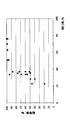
- FIG. 6 shows the result of calculating the change in peel force when the pitch of the concavo-convex structure Ca is set as a variable. In FIG.
- the horizontal axis represents the pitch of the concavo-convex structure Ca
- the vertical axis represents the value (specific peeling energy) normalized with the peeling energy when peeling the carrier as 1 when the pitch is 100 nm.
- FIG. 6 shows that the specific peeling energy increases as the pitch of the concavo-convex structure Ca increases.
- a carrier was produced using the pitch of the concavo-convex structure Ca as a variable, and the transferability was evaluated. As a result, it was confirmed that transfer could be easily performed if the pitch was up to 1.5 ⁇ m. That is, it can be said that the range where the specific peeling energy in FIG. 6 is up to about 3.2 is a suitable range for the functional transfer body. The calculation method of FIG. 6 will be described later.
- the pitch of the concavo-convex structure Ca is in the micrometer region, the microneedle array, the concavo-convex for the high-intensity LED (for example, PSS (Patterned Sapphire Substrate), the concavo-convex for the transparent conductive film, the concavo-convex for the p-type semiconductor layer, the n-type
- PSS Panelned Sapphire Substrate
- the concavo-convex for the transparent conductive film for example, the concavo-convex for the transparent conductive film, the concavo-convex for the p-type semiconductor layer, the n-type
- There are many useful applications such as irregularities on the semiconductor layer), microchannels, or liquid crystal alignment paths. In particular, for these applications, since it is difficult to process a target size, there is a problem in expanding to a large area.
- the function transfer body of the embodiment has a very large margin for the formation of the concavo-convex structure Fu with respect to the size and shape of the object to be processed. That is, it can be said that it is extremely useful if the functional transfer body of the embodiment can be used to transfer the concavo-convex structure Fu on the order of micrometers to the object to be processed.
- the upper limit of the pitch is 10 ⁇ m.
- the specific peeling energy increases and the transferability deteriorates.
- the pitch of the concavo-convex structure Ca is in a region exceeding 1.5 ⁇ m, it is possible to reduce the specific separation energy and improve the transferability by controlling the aperture ratio of the concavo-convex structure. I found out. From the result of FIG. 6, it was considered that the peeling energy was almost saturated in the region where the pitch of the concavo-convex structure Ca was 2.5 ⁇ m or more.
- the peeling energy was calculated by taking the aperture ratio of the concavo-convex structure Ca as a variable.
- the horizontal axis represents the opening ratio of the concavo-convex structure Ca
- the vertical axis represents the peeling energy when the carrier is peeled and the concavo-convex structure Fu is transferred to the object to be processed, assuming that the opening ratio is 21% and is normalized to 1. (Specific peeling energy). From FIG. 7, it can be seen that the larger the aperture ratio, the lower the peeling energy. From the actual examination, it is known from the notation of FIG.
- the peeling energy was calculated from the adhesive energy at the interface between the concavo-convex structure Ca and the concavo-convex structure Fu.
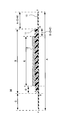
- the concavo-convex structure Ca has a plurality of recesses, and these recesses are arranged in a regular hexagon.
- the shape of the recess was a bell shape.
- the pitch of the concavo-convex structure Ca was set when obtaining FIG. 6, and the aperture ratio of the concavo-convex structure Ca was set when obtaining FIG.
- the width of the transfer area of the functional transfer body was 250 mm, and a model was prepared that peels at a peel angle of 91 ° with a force of 0.01 N.
- the peeling energy was calculated as dimensional erg / cm 2 as Gibbs free energy released when the carrier was peeled and removed, and converted to dimension J by multiplying the shape and density of the concave portion of the concavo-convex structure Ca.
- the pitch of the concavo-convex structure Ca was set as the shortest distance between the centers of the openings of the concave portions.
- the aperture ratio was set as the ratio of the opening when the concavo-convex structure Ca was viewed in plan.
- Duty is a ratio (opening diameter / pitch).
- the functional raw material is diluted in a solvent and the wettability is secured by a solvent or an additive is taken as an example.
- the concentration of the functional raw material is improved and the viscosity of the coating film is increased.
- the influence which the coating film located above the convex part of the concavo-convex structure Ca receives from the concavo-convex structure Ca is different from the influence which the coating film located above the concave opening of the concavo-convex structure Ca receives from the concave-convex structure Ca. .
- the functional layer is fixed in a state affected by the concavo-convex structure Ca. Accuracy is reduced. This means that the distribution of film thickness (t) becomes large. That is, the surface roughness (Ra) of the functional layer increases, the ratio (Ra / t) increases, and the transferability decreases. The deterioration of the film thickness (t) distribution based on such a principle becomes more prominent as the pitch of the concavo-convex structure Ca increases.
- TPCL is an abbreviation for Three Phase Contact Line, and refers to a three-phase interface of gas, liquid, and solid.
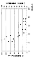
- the horizontal axis of FIG. 8 indicates the aperture ratio of the concavo-convex structure Ca, and the vertical axis indicates the ratio (Ra / t).
- the pitch of the concavo-convex structure Ca is 2.5 ⁇ m is a round mark and a square mark, and the case where the pitch is 5 ⁇ m is a triangle mark and a cross mark.
- the case where the film thickness (t) was 100 nm was expressed as a circle mark and a triangle mark
- the case where the film thickness (t) was 10000 nm was expressed as a square mark and a cross mark.
- the pitch 2.5 ⁇ m and 5 ⁇ m were used in order to match the examination result of transferability and to determine the influence of the pitch. From this, it can be seen that the ratio (Ra / t) deteriorates as the pitch increases. That is, it has been found that it is necessary to adjust the ratio (Ra / t) for a larger pitch.
- the film thickness (t) was determined from the viewpoint of the use of the concavo-convex structure Fu of more than 1.5 ⁇ m, because it was more practical than a margin of 100 nm to 10000 nm.
- the ratio (Ra / t) deteriorates as the film thickness (t) is thinner, it is necessary to adjust the ratio (Ra / t) with respect to the thinner film thickness (t). It was. From the above, it is important that the ratio (Ra / t) can be adjusted when the pitch of the concavo-convex structure Ca is 5 ⁇ m and the film thickness (t) is 100 nm.
- the ratio (Ra / t) is desirably 1.2 or less for the reasons already described.
- the ratio (Ra / t) is 1.2 or less. It can be seen that it can be controlled. Since the assumption of the calculation is that the ratio (Ra / t) is the worst, in reality, the margin should be wider. In other words, the accuracy of arrangement of the functional layer with respect to the concavo-convex structure Ca is improved by adding the constraint that the aperture ratio is 40% or more. The transferability of the concavo-convex structure Fu is further improved due to the effects of the discussion and the ratio (Ra / t) described above.
- the concavo-convex structure Fu capable of expressing the micro-order function when the pitch of the concavo-convex structure Ca is more than 1.5 ⁇ m and the aperture ratio is 40% or more. It can be transferred and formed on the object with high accuracy.
- the upper limit of a pitch changes with a use, it is 10 micrometers from a viewpoint of expressing the function of a micrometer order.
- the transferability is further improved when the aperture ratio is 45% or more.
- the accuracy of the film thickness (t) is further improved.
- An aperture ratio of 55% or more is preferable because both the accuracy of film thickness (t) and transferability are improved.
- the functional transfer body includes a protective layer as an essential component. That is, in the production of the functional transfer body, it can be said that the stability when the protective layer is bonded and wound is important, and hereinafter, it is expressed as laminating property. On the other hand, when the functional transfer body is used, since the protective layer is used after being peeled off, it can be said that the stability at the time of peeling off the protective layer is important. When the adhesion between the protective layer and the functional layer is low when the protective layer is bonded, the protective layer slips on the functional layer and wrinkles occur during winding. That is, the laminating property is lowered.
- the functional layer in the functional transfer body is characterized in that a suitable material can be selected according to the application. Also, the adhesion force between two bodies can be calculated as the difference in free energy between the two bodies, and the free energy can be estimated from the contact angle. It is considered that there is a suitable range for the contact angle of the water droplet with the surface to be rubbed. If the contact angle of the water droplet with respect to the surface bonded to the functional layer of a protective layer is 75 degree or more and 105 degrees or less, since lamination property and peelability improve more, it is preferable.
- the adhesive force between the two bodies is defined as the difference in free energy between the two bodies, and since the free energy can be estimated by the contact angle, the contact angle of the protective layer is controlled within a predetermined range. Thus, it is presumed that the free energy between the two bodies increases for the laminate property and decreases for the peelability.
- the contact angle using water droplets is measured in accordance with Japanese Industrial Standard JISR 3257: 1999 “Test Method for Wetting of Substrate Glass Surface”.
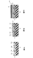
- FIG. 1 and 2 are schematic cross-sectional views showing each step of a method for imparting a function to an object to be processed using the function transfer body according to the present embodiment.
- the carrier 10 has an uneven structure 11 formed on the main surface thereof.
- the concavo-convex structure 11 is a concavo-convex structure Ca composed of a plurality of concave portions 11a and convex portions 11b.
- the carrier 10 is, for example, a film shape or a sheet shape.
- the film shape has a property that the film thickness is extremely thin with respect to the length and width, is flexible, and can be formed into a roll shape.
- a sheet form refers to a thin flat plate-like object, and its flexibility is not limited.
- disconnected the film-like functional transfer body in the length direction and made it into every leaf is a sheet form. However, in each embodiment, the two should not be clearly distinguished.
- a functional layer 12 is provided on the surface of the concavo-convex structure 11 of the carrier 10.
- the arrangement of the functional layers 12 and the number of functional layers 12 are not limited to this.
- a protective layer 13 is provided on the upper side of the functional layer 12. The protective layer 13 protects the functional layer 12.
- a laminate including the carrier 10, the functional layer 12, and the protective layer 13 is referred to as a functional transfer body 14.
- a workpiece 20 as shown in FIG. 2A is prepared.
- the exposed surface of the functional layer 12 of the functional transfer body 14 after removing the protective layer 13 is brought into direct contact with the main surface of the target object 20.
- the carrier 10 is removed from the functional layer 12.
- a laminated body 21 including the functional layer 12 and the target object 20 is obtained.
- the uneven structure of the stacked body 21 is an uneven structure Fu.
- the laminated body 21 can be used in the state of the laminated body 21 depending on its application, or can be used after the processed body 20 is processed by functioning as a processing mask of the processed body 20.
- the functional layer 12 is stabilized by irradiating the laminated body 21 with an energy ray. Further, for example, the functional layer 12 is stabilized by heat applied at the time of contact. For example, after irradiating the laminated body 21 with energy rays, the laminated body 21 is heated to stabilize the functional layer 12. Moreover, when irradiating an energy ray, the laminated body 21 which comprises the patterned functional layer 12 can be obtained by providing the light shielding mask with respect to an energy ray. In patterning, if a positive-type developable functional layer is provided, energy rays can be irradiated after the carrier 10 is peeled off. If a negative-type developable functional layer is provided, the carrier 10 can be peeled after irradiation with energy rays.
- the composition of the functional layer 12 of the functional transfer body 14 will be described.
- the functional layer 12 includes a resin
- the arrangement accuracy of the functional layer 12 is improved regardless of the composition of the functional layer 12, and the adhesive strength between the functional layer 12 and the target object 20 is increased.
- the uneven structure F with few defects can be imparted to the workpiece 20.
- the composition of the functional layer 12 is not particularly limited, and may be an organic material, an inorganic material, or an organic-inorganic composite.
- organic-inorganic hybrid oligomers, polymerizable resins, polymerizable monomers, metal alkoxides, metal alcoholates, metal chelate compounds, halogenated silanes, spin-on-glass, metals, or metal oxides can be used.
- the functional layer 12 containing a resin can reduce the hardness of the functional layer 12 and can improve the placement stability of the functional layer 12. Thereby, the controllability of the surface roughness (Ra) of the functional layer by the protective layer 13 is improved. That is, hole defects in the functional layer can be suppressed. This improves the accuracy and film thickness accuracy of the concavo-convex structure 11 of the functional layer 12 and suppresses the occurrence of cracks in the functional layer 12 even when the functional transfer body 14 is rolled up into a reel shape, for example. it can. Moreover, since the physical stability of the functional layer 12 of the functional transfer body 14 is improved by including the resin in the functional layer 12, the arrangement accuracy of the functional layer 12 is lowered by the conveyance and handling of the functional transfer body 14.
- the resin in this specification is defined as an oligomer or polymer having a molecular weight of 1000 or more.
- the resin structure include organic resins, inorganic resins, and organic-inorganic hybrid resins. These may contain only 1 type, or may contain multiple. These resins can employ known general oligomers or polymers.
- a photoresist resin for example, in general, a photoresist resin, a nanoimprint resin, an adhesive resin, an adhesive resin, a dry film resist resin, an engineering plastic, a sealing resin, rubber, plastic, fiber, medical plastic, or Pharmaceutical resins can be used. Natural polymers can also be used.
- the weight average molecular weight of the resin is preferably 1,000 to 1,000,000 from the arrangement accuracy of the functional layer 12.
- the lower limit of 1000 was determined from the decrease in hardness of the functional layer 12 and the physical stability of the functional layer 12.
- the upper limit value of 1000000 was determined from the arrangement accuracy of the functional layer 12 with respect to the concavo-convex structure 11 in consideration of the range of the average pitch of the concavo-convex structure 11.
- the range of the average pitch is determined from the viewpoint of weakening the stress applied from the concavo-convex structure 11 of the carrier 10 to the functional layer 12, maintaining good flatness of the surface of the functional layer 12, and reducing hole defects in the functional layer 12. It had been.
- the weight average molecular weight is preferably 500,000 or less, more preferably 100,000, and still more preferably 60000.
- the dispersion degree of the resin is approximately 1 to 6, and preferably 1 to 4.
- the degree of dispersion is the ratio of the weight average molecular weight to the number average molecular weight (weight average molecular weight) / (number average molecular weight).
- the molecular weight was measured by gel permeation chromatography (GPC) manufactured by JASCO Corporation (pump: Gulliver, PU-1580 type, column: Shodex (registered trademark) manufactured by Showa Denko KK (KF-807, KF-806M, KF- 806M, KF-802.5) 4 in series, moving bed solvent: tetrahydrofuran, using calibration curve with polystyrene standard sample), and can be determined as weight average molecular weight (polystyrene conversion).
- the resin is preferably provided at least in the functional layer 12 in contact with the protective layer 13 side.
- an inorganic material containing an oxide of Si, Ti, Zr, or In is formed on the concavo-convex structure 11 of the carrier 10, a layer containing a resin is formed on the inorganic material, and the protective layer 13 is pasted.
- a functional transfer body 14 can be obtained.
- the resin contained in the functional layer 12 preferably has a polar group.
- the intermolecular interaction in the functional layer 12 can be strengthened, the adhesion between the functional layer 12 and the concavo-convex structure 11 can be reduced.
- the electrostatic interaction or hydrogen bonding action on the interface between the functional layer 12 and the object to be processed 20 tends to be strong, the adhesive strength between the functional layer 12 and the object to be processed 20 is improved.
- transferability can be improved by including a polar group.
- the type of the polar group is not particularly limited, but epoxy group, hydroxyl group, phenolic hydroxyl group, acryloyl group, methacryloyl group, vinyl group, carboxyl group, carbonyl group, amino group, allyl group, diquitacene group, cyano group, isocyanate group, phosphorus
- epoxy group hydroxyl group, phenolic hydroxyl group, acryloyl group, methacryloyl group, vinyl group, carboxyl group, carbonyl group, amino group, allyl group, diquitacene group, cyano group, isocyanate group, phosphorus
- an epoxy group preferably contains at least one polar group of the group consisting of carbonyl group, amino group and isocyanate group.
- the interfacial adhesive force between the concavo-convex structure 11 of the carrier 10 and the functional layer 12 is further reduced, and transferability is further improved, which is preferable.
- the said effect becomes larger by including at least 1 or more of the group which consists of an epoxy group, a hydroxyl group, an acryloyl group, a methacryloyl group, a vinyl group, and a carboxyl group.
- the volume of the functional layer 12 of the functional transfer body 14 tends to be smaller than the volume of the functional layer 12 when the carrier 10 is removed. That is, at the stage of removing the carrier 10 from the functional layer 12, a gap larger than the molecular scale can be formed at the interface between the concavo-convex structure 11 of the carrier 10 and the functional layer 12. This means that the adhesion between the concavo-convex structure 11 and the functional layer 12 is greatly reduced, so that the peeling speed of the carrier 10 can be sufficiently increased.
- the curable resin is a resin that is cured by heat, light, or heat and light.
- thermosetting resin a thermosetting resin
- a phenol resin a urea resin, a melamine resin, an unsaturated polyester resin, an epoxy resin, or a silicon resin
- a photo-curable resin a resin having an epoxy group, an acryloyl group, a methacryloyl group, a vinyl group, or the like can be given.
- a curable resin it is preferable to include a curing initiator suitable for the curing principle. A photopolymerization initiator can be applied to the photocurable resin.
- a known general radical polymerization initiator, cationic polymerization initiator, or anionic polymerization initiator can be used. These can also be used in combination.
- a thermal polymerization initiator can be applied to the thermal polymerization resin.
- a known general azo compound can be used.
- a thermal polymerization initiator can also be used with respect to photocurable resin.
- a photosensitizer can be added.
- the resin preferably contains a resin containing at least one repeating unit. Further, this repeating unit has a ratio (Na / (Nc-No) where Na is the total number of atoms constituting the repeating unit, Nc is the number of carbon atoms in the repeating unit, and No is the number of oxygen atoms in the repeating unit. )) Is preferably a repeating unit having a ratio K of 5.5 or less. That is, when a state where there are three repeating units is represented, in the general formula represented by-(A) x- (B) y- (C) z-, at least one or more of A, B or C is repeated. The unit satisfies the ratio K ⁇ 5.5.
- the ratio K should satisfy 4.0 or less. More preferably, it is most preferable to satisfy 3.5 or less. In particular, when the ratio K is 3.0 or less, the carbon density in the resin increases, so that the chemical action between the functional layer 12 and the concavo-convex structure 11 can be reduced, and the adhesion can be further reduced. In addition, by satisfying these ranges, the processing accuracy is greatly improved when the workpiece 20 is processed to be uneven using the functional layer 12 of the stacked body 21 as a processing mask.
- the number of repeating units is 2 or more, at least one repeating unit satisfies the above ratio K.
- the number of repetitions of the repeating unit G satisfying the ratio K and the repeating unit B not satisfying the ratio K preferably satisfies the following range.
- the total value of the number of repeating units G is ⁇ , and the total number of the repeating units B is ⁇ .
- ⁇ / ⁇ ⁇ 1 because the effect of intramolecular interaction is increased and transferability is improved.
- satisfying ⁇ / ⁇ ⁇ 1.5 is preferable because intermolecular interaction can also be used and transferability is further improved.
- ⁇ / ⁇ is 2.3 or more
- the functional layer 12 and the concavo-convex structure are preferable.
- 11 is preferable because the effect of suppressing the chemical interaction at the interface with the substrate 11 is increased. From the viewpoint of further exerting the above effects, ⁇ / ⁇ is more preferably 4 or more, and ⁇ / ⁇ is most preferably 9 or more.
- the maximum value of the difference K between the repeating units is 3.5 or less.
- ⁇ Kmax is 3.5 or less.
- an intermolecular interaction can be expressed effectively.
- the intramolecular interaction is increased.
- it is 2.5 or less, the stability of the resin is improved, and the effect of suppressing the chemical action at the interface between the functional layer 12 and the concavo-convex structure 11 is enhanced.
- it is preferably 2.0 or less, and preferably 1.5 or less. More preferably, it is most preferably 1.0 or less.
- the processing accuracy is greatly improved when the workpiece 20 is processed to be uneven using the functional layer 12 of the stacked body 21 as a processing mask.
- the functional layer 12 preferably includes a material having an annular portion. This is because the inclusion of a material having an annular portion tends to induce an increase in the hardness of the functional layer 12 and a volume shrinkage of the functional layer 12 due to packing and arrangement of the annular portions. That is, there are effects of suppressing the cohesive failure of the functional layer 12 when the carrier 10 is removed from the functional layer 12 and reducing the adhesion between the concavo-convex structure 11 of the carrier 10 and the functional layer 12. In particular, this effect is enhanced when the cyclic part is a cyclic part having 30 or less carbon atoms.
- the cyclic portion is composed of at least one element selected from the group consisting of a 4-membered ring, a 5-membered ring, and a 6-membered ring, the packing property is improved, so that the free energy of the functional layer 12 is reduced. It tends to decrease. That is, since the chemical action between the concavo-convex structure 11 of the carrier 10 and the functional layer 12 can be reduced, transferability is improved.
- the cyclic portion may be contained in the above-described resin, or may be contained in other components such as a monomer.
- the functional layer 12 includes a resin and a monomer, it is preferable that at least the resin includes the cyclic portion.
- the cyclic moiety include at least one cyclic moiety selected from the following chemical formula group A. These may include only one type or two or more types.
- “*” Represented in the chemical formula is bonded to another element via “*”, and “*” represents oxygen element (O), nitrogen element (N), sulfur element (S) or carbon element ( C). Further, the portion lacking a bond is bonded to a hydrogen element (H), a methyl group (CH 3 ), or a hydroxyl group (OH).
- the resin having the above cyclic moiety polystyrene, poly p-hydroxystyrene, poly-9 vinyl carbazole, a resin having a carbazole skeleton, a resin having a carbazole skeleton in the side chain, a resin having a cresol novolak skeleton, phenol Resin having novolak skeleton, resin having bisphenol A skeleton, resin having fluorene skeleton, resin having adamantane skeleton in side chain, resin having adamantyl skeleton in side chain, or norbornane skeleton in side chain
- the resin which has is mentioned.
- the resin may be an alkali-soluble resin.
- the functional layer 12 of the laminate 21 can be easily developed to form an uneven structure.
- the resin preferably contains a carboxyl group.
- the amount of the carboxyl group is preferably from 100 to 600 as an acid equivalent, and more preferably from 300 to 450.
- An acid equivalent shows the mass of the linear polymer which has a 1 equivalent carboxyl group in it. The acid equivalent is measured by a potentiometric titration method using a Hiranuma automatic titrator (COM-555) manufactured by Hiranuma Sangyo Co., Ltd., using a 0.1 mol / L sodium hydroxide aqueous solution.
- COM-555 Hiranuma automatic titrator
- the first monomer is a carboxylic acid or acid anhydride having one polymerizable unsaturated group (for example, acrylate or methacrylate) in the molecule.
- the second monomer is non-acidic and is a compound having one polymerizable unsaturated group in the molecule, and is selected so as to maintain various properties such as flexibility of the cured film and resistance to dry etching. .
- the polar group already described can be arbitrarily included in the resin.
- the functional layer 12 preferably contains a monomer in addition to the resin described above. That is, it preferably contains a resin and a monomer.
- the monomer is defined as a substance other than the resin defined by this specification and a substance other than the solid fine particles and the solid filler. That is, any of an organic substance, an inorganic substance, or an organic-inorganic composite can be employed.
- the monomer whose mobility is inhibited by the resin is brought into contact with the object 20 to be processed, the mobility is released and the fluidity of the surface layer of the functional layer 12 is further improved. it can.
- the resin and the monomer are contained in the outermost layer of the functional layer 12, the above effect becomes more remarkable.
- the combination of resin and monomer may be any of (organic matter / organic matter), (organic matter / inorganic matter), (inorganic matter / inorganic matter), or (inorganic matter / organic matter) as long as it is described as (resin / monomer).
- a metal alkoxide can be added to an organic resin that satisfies the above-described resin requirements. If it is (inorganic / inorganic), a metal alkoxide can be added to an inorganic resin that satisfies the above-mentioned requirements, such as a metal polymer or a metal oxide polymer.
- an organic monomer can be added to an inorganic resin that satisfies the resin requirement satisfying the above requirements, for example, a metal polymer or a metal oxide polymer.
- the metal alkoxide may be used as a monomer, or a condensed quanta or oligomer may be used.
- At least one of the resin and the monomer is preferably a curable substance, and at least the monomer is preferably a curable substance.
- the curable substance may be replaced with a substance of the curable resin.
- the contracting action of the functional layer 12 is increased, the interfacial adhesive strength between the concavo-convex structure 11 and the functional layer 12 is reduced, and the transferability is improved.
- the effect becomes greater.
- the viscosity of the monomer is preferably approximately 5 cP to 5000 cP at 25 ° C., more preferably 8 cP to 2500 cP, and most preferably 10 cP to 1500 cP.
- the viscosity here means the viscosity with respect to the mixture when all the monomers to be used are mixed.
- the average number of functional groups of the monomer is preferably 1 or more and 6 or less, preferably 1 or more and 4 or less. The following is preferable, and 1.5 to 3 is most preferable.
- hexafunctional (meth) acrylate and bifunctional (meth) acrylate can be mixed to adjust the average number of functional groups.
- trifunctional (meth) acrylate and bifunctional (meth) acrylate can be mixed to adjust the average number of functional groups.
- the monomer is a monomer including a cyclic moiety selected from the above chemical formula group A
- the effect of physical stability due to the cyclic moiety and the effect of reducing the chemical interaction with the surface of the concavo-convex structure 11 are increased. Due to the tendency, transferability is improved. Further, in this case, the processing accuracy when the object 20 is processed to be uneven is also improved.
- the functional layer 12 can contain coloring substances such as dyes and pigments. Whether or not the transfer is performed well even when the size of the concavo-convex structure 11 is sufficiently smaller than the wavelength of visible light when the functional layer 12 is transferred and formed on the object to be processed 20 by containing the coloring matter. It can be judged by visual and optical detection means. Furthermore, the absorption of the colored substance can be used for quality control of the functional layer 12 formed on the concavo-convex structure 11 of the carrier 10. The coloring substance can be appropriately selected so as not to hinder the function derived from the uneven structure 11 of the functional layer 12.
- a coloring dye represented by a combination of a leuco dye or a fluoran dye and a halogen compound can also be used. Of these, a combination of tribromomethylphenylsulfone and a leuco dye or a combination of a triazine compound and a leuco dye is useful.
- an antioxidant can be included.
- the antioxidant is preferably a light stabilizer.
- the light stabilizer can be classified into a radical chain initiation inhibitor, a radical scavenger, and a peroxide decomposer, and any of them can be adopted.
- Radical chain initiation inhibitors can be further classified into heavy metal deactivators and UV absorbers, heavy metal deactivators mainly include hydrazide and amide types, UV absorbers mainly include benzotriazole, There are benzophenone series and triazine series. Among these, an ultraviolet absorber is more preferable. Since the functional layer 12 can be optically stabilized by including the ultraviolet absorber, it can be used in a place suitable for use. Further, radical scavengers can be classified into HALS and phenolic antioxidants. As these antioxidants, known general materials can be used.
- an additive such as a plasticizer can be contained in the functional layer 12 as necessary.
- additives include phthalic acid esters such as diethyl phthalate, p-toluenesulfonamide, polypropylene glycol, or polyethylene glycol monoalkyl ether.
- the metal element applicable to the functional layer 12 of the functional transfer body 14 can be appropriately selected depending on the use of the laminate. Especially manganese (Mn), cobalt (Co), nickel (Ni), copper (Cu), rubidium (Rb), niobium (Nb), molybdenum (Mo), technetium (Tc), ruthenium (Ru), palladium (Pd) , Silver (Ag), cesium (Cs), osmium (Os), platinum (Pt), gold (Au), potassium (K), lithium (Li), sodium (Na), barium (Ba), calcium (Ca) , Magnesium (Mg), lead (Pb), strontium (Sr), zinc (Zn), aluminum (Al), boron (B), bismuth (Bi), iron (Fe), gallium (Ga), indium (In) , Lanthanum (La), antimony (Sb), vanadium (V), yttrium (Y), germanium (Ge), hafnium (
- the functional layer 12 is a multilayer functional layer 12 having two or more layers and the other functional layers 12 are processed by the one or more functional layers 12, titanium (Ti), zirconium (Zr), chromium (Cr), zinc (Zn), tin (Sn), boron (B), indium (In), aluminum (Al), silicon (Si), molybdenum (Mo), tungsten (W) and germanium (Ge) It is preferably at least one selected from the group.
- titanium (Ti), zirconium (Zr), chromium (Cr), silicon (Si) or zinc (Zn) is preferable, and titanium (Ti), zirconium (Zr), silicon (Si) or zinc (Zn) ) Is most preferred.
- the functional layer 12 preferably contains a metalloxane bond (—O—Me1-O-Me2-O—), particularly from the viewpoint of improving chemical stability.
- Me1 and Me2 are both metal elements and may be the same metal element or different.
- the above-described metal element can be employed.
- —O—Ti—O—Ti—O—, —O—Zr—O—Zr—O—, and —O—Si—O—Si—O—O—O— can be mentioned.
- —O—Ti—O—Si—O—, —O—Zr—O—Si—O—, —O—Zn—O—Si—O—, —O—Ti—O—Zr —O—, —O—Ti—O—Zn—O—, —O—Ti—O—Si—O—Zn—O—, and the like can be given.
- three or more types of metal element species in the metalloxane bond may be included.
- the metal element contained in the functional layer 12 has a ratio (C pM1 / C pSi ) between the Si element concentration (C pSi ) and the total concentration (C pM1 ) of metal elements other than Si of 0.02 or more and less than 24 It is preferable because the transfer accuracy is improved.
- the functional layer 12 is the multilayer functional layer 12 of 2 or more, and the processing precision at the time of carrying out uneven
- the ratio (C pM1 / C pSi) is set small to be a small refractive index of the functional layer 12, by increasing the ratio (C pM1 / C pSi), increasing the refractive index of the functional layer 12 Can do.
- the inertial radius with respect to the functional coating solution of 3 wt% is 5 nm or less from the viewpoint of suppressing the disposition accuracy and aggregation of the functional layer 12.
- the inertia radius is preferably 3 nm or less, more preferably 1.5 nm or less, and most preferably 1 nm or less.
- the inertia radius is a radius calculated by applying a Gunier plot to a measurement result obtained by measurement by small angle X-ray scattering (SAXS) using X-rays having a wavelength of 0.154 nm.
- SAXS small angle X-ray scattering
- propylene glycol monomethyl ether is used as the solvent.
- the functional layer 12 has a multilayer structure of two or more, and in the state of the laminate 21, the one or more functional layers 12 (hereinafter sometimes referred to as the functional layer 1) function as a processing mask for other functional layers.
- the functional layer 1 functioning as a processing mask includes the inorganic material or organic-inorganic composite exemplified above. Is preferred. Particularly in this case, it is most preferable to fill and dispose the functional layer 1 only in the concave portion 11a of the concave-convex structure 11 of the carrier 10 and to provide the functional layer 2 so as to flatten the functional layer 1 and the concave-convex structure 11 of the carrier 10 together. preferable.
- the selection ratio between the functional layer 1 and the functional layer 2, that is, the ratio (Vo1 / Vm1) between the etching rate (Vm1) of the functional layer 1 and the etching rate (Vo1) of the functional layer 2 by dry etching is This affects the processing accuracy when the functional layer 2 is etched using the layer 1 as a mask.
- Vo1 / Vm1> 1 means that the functional layer 1 is less likely to be etched than the functional layer 2, so that (Vo1 / Vm1) is preferably as large as possible.
- (Vo1 / Vm1) preferably satisfies Vo1 / Vm1 ⁇ 150, and more preferably satisfies Vo1 / Vm1 ⁇ 100, from the viewpoint of the coating property of the functional layer 1. Further, (Vo1 / Vm1) preferably satisfies 3 ⁇ (Vo1 / Vm1), more preferably satisfies 10 ⁇ Vo1 / Vm1, and preferably satisfies 15 ⁇ Vo1 / Vm1 from the viewpoint of etching resistance. Further preferred.
- the thick functional layer 2 can be easily roughened by dry etching using the functional layer 1 as a mask.
- the functional layer 1 and the functional layer 2 that are processed to be uneven by dry etching can be formed on the object 20 to be processed.
- the material of the functional layer 1 that functions as a mask for processing is not particularly limited as long as the above selection ratio is satisfied.
- Various known resins (organic substances) that can be diluted in a solvent, inorganic precursors, inorganic condensates, plating solutions (Chromium plating solution etc.), metal oxide filler, metal oxide fine particles, silsesquioxane represented by HSQ, spin-on-glass, metal fine particles and the like can be used.
- the functional layer 1 uses the functional transfer body 14 to chemically bond the functional layer 1 and the functional layer 2 or form hydrogen bonds from the viewpoint of transfer accuracy when the laminate 21 is transferred and formed. It is preferable to do.
- the functional layer 1 includes either or both of a photopolymerizable group capable of photopolymerization and a polymerizable group capable of thermal polymerization.
- the functional layer 1 preferably contains a metal element from the viewpoint of dry etching resistance. Furthermore, it is preferable that the functional layer 1 contains metal oxide fine particles because processing during dry etching of the workpiece 20 becomes easier.
- the metal element contained in the functional layer 1 As the metal element contained in the functional layer 1, the metal element described above can be adopted.
- the functional layer 1 is more stable than the laminate 21 in which the metal element contained in the functional layer 1 stably exists and satisfies the dry etching resistance described later, and is composed of the functional layer 1 / functional layer 2 / processed body 20.
- the functional layer 1 preferably contains a metalloxane bond (-O-Me1-O-Me2-O-) from the viewpoint of improving the processing accuracy when the functional layer 2 is etched.
- the metalloxane bond is as already described.
- three or more types of metal element species in the metalloxane bond may be included. In particular, when two or more types are included, it is preferable to include at least Si from the viewpoint of transfer accuracy of the mask layer.
- the ratio (C pM1 / C pSi ) between the Si element concentration (C pSi ) in the entire functional layer 1 and the total concentration (C pM1 ) of metal elements other than Si is 0 0.02 or more and less than 24 is preferable because the processing accuracy is improved when the functional layer 2 is etched using the functional layer 1 as a mask.
- it is more preferably 0.05 or more and 20 or less, and most preferably 0.1 or more and 15 or less.
- Examples of a method for including such a metalloxane bond in the functional layer 1 include a method of using a metal element or a method of condensing an inorganic precursor.
- a method for condensing the inorganic precursor for example, the reaction by hydrolysis and polycondensation of the metal alkoxide described above can be used.
- Examples of a method of using a metal element in the functional layer 1 include a method of including a sol-gel material typified by metal oxide fine particles (filler), metal fine particles, or metal alkoxide in the material of the functional layer 1.
- a sol-gel material used for the functional layer 1 for example, a metal alkoxide can be used.
- the sol-gel material preferably contains at least two types of metal alkoxides having different metal types. Examples of combinations of metal species of two types of metal alkoxides having different metal species include Si and Ti, Si and Zr, Si and Ta, and Si and Zn.
- the ratio C M1 / C Si of the molar concentration (C Si ) of the metal alkoxide having Si as a metal species and the metal alkoxide (C M1 ) having a metal species M1 other than Si is 0. 2 to 15 is preferable.
- C M1 / C Si may be 0.5 to 15. preferable.
- C M1 / C Si is more preferably 5 to 8.
- C M1 / C Si is in the range of 0.2 to 10 in the widest range (0.2 to 15), the functional layer 1 when the functional layer 2 is etched using the functional layer 1 as a mask.
- the range of 0.2 to 5 is preferable because the physical stability of the functional layer 1 during etching is improved, and the range of 0.2 to 3.5 is more preferable.
- the contour shape stability of the functional layer 1 is improved when the functional layer 2 is etched using the functional layer 1 of 0.23 to 3.5 as a mask. From the same viewpoint, it is more preferably 0.25 to 2.5.
- the functional layer 1 is preferably a hybrid including an inorganic segment and an organic segment from the viewpoint of transfer accuracy and dry etching resistance of the functional layer 1.
- Hybrids include, for example, a combination of inorganic fine particles and a resin that can be photopolymerized (or thermally polymerized), a resin that can be photopolymerized (or thermally polymerized) with an inorganic precursor, a molecule in which an organic polymer and an inorganic segment are bonded by a covalent bond.
- the inorganic precursor etc. which comprise an inorganic precursor and a photopolymerizable group in a molecule
- the sol-gel material when used as the inorganic precursor, it means that a photopolymerizable resin is included in addition to the sol-gel material containing the silane coupling agent.
- a photopolymerizable resin is included in addition to the sol-gel material containing the silane coupling agent.
- a hybrid for example, a metal alkoxide, a silane coupling material having a photopolymerizable group, a radical polymerization resin, or the like can be mixed.
- silicone may be added thereto.
- the sol-gel material portion may be pre-condensed in advance.
- the mixing ratio of the metal alkoxide containing the silane coupling agent and the photopolymerizable resin is preferably in the range of 3: 7 to 7: 3 from the viewpoint of dry etching resistance and transfer accuracy. More preferably, it is in the range of 3.5: 6.5 to 6.5: 3.5.
- the resin used for the hybrid is not particularly limited as long as it can be photopolymerized, whether it is a radical polymerization system or a cationic polymerization system.
- an inorganic precursor having a photopolymerizable group in the molecule when adopting an inorganic precursor having a photopolymerizable group in the molecule as a hybrid, a metal alkoxide having a metal element other than Si as a metal species is used as the inorganic precursor, and photopolymerizability is achieved.
- a silane coupling material having a photopolymerizable group can be employed as an inorganic precursor having a group in the molecule. These silicones can also be included.
- a molecule in which an organic polymer and an inorganic segment are bonded by a covalent bond or an inorganic precursor having an inorganic precursor and a photopolymerizable group in the molecule.
- an inorganic precursor having an inorganic precursor and a photopolymerizable group in the molecule for example, a metal alkoxide is selected as the inorganic precursor, and a photopolymerizable group is used as the inorganic precursor having the photopolymerizable group in the molecule.
- a silane coupling material comprising
- the metal species of the metal alkoxide used as the inorganic precursor is preferably Ti, Ta, Zr or Zn, and most preferably Ti, Zr or Zn.
- Examples of the photopolymerizable group contained in the functional layer 1 include an acryloyl group, a methacryloyl group, an acryloxy group, a methacryloxy group, an acrylic group, a methacryl group, a vinyl group, an epoxy group, an allyl group, and an oxetanyl group.
- the known resin contained in the functional layer 1 includes both photopolymerizable and thermally polymerizable resins, or any one of them.
- a photosensitive resin used in photolithography applications a photopolymerizable resin or a thermopolymerizable resin used in nanoimprint lithography applications, and the like can be given.
- a resin satisfying the ratio (Vo1 / Vm1) between the etching rate (Vm1) of the resin contained in the functional layer 1 and the etching rate (Vo1) of the functional layer 2 by dry etching satisfies 1 ⁇ Vo1 / Vm1 ⁇ 50. It is preferable to contain.
- the material forming the functional layer 1 preferably includes a sol-gel material.
- a sol-gel material By including the sol-gel material, not only the functional layer 1 having good dry etching resistance can be easily filled into the concavo-convex structure 11 of the carrier 10, but also in the vertical direction when the functional layer 2 is dry-etched. dry etching rate (Vr ⁇ ), the ratio of the lateral dry etching rate (Vr //) (Vr ⁇ / Vr //) can be increased.
- the sol-gel material only a metal alkoxide having a single metal species may be used, or a metal alkoxide having a different metal species may be used in combination, but the metal species M1 (where M1 is Ti, Zr, Zn, It is preferable to contain at least two kinds of metal alkoxides, ie, a metal alkoxide having at least one metal element selected from the group consisting of Sn, B, In, and Al) and a metal alkoxide having the metal kind Si. .
- the hybrid of these sol-gel materials and well-known photopolymerizable resin can also be used as a functional layer 1 material.
- the material of the functional layer 1 preferably has a small phase separation after curing by both condensation and / or photopolymerization from the viewpoint of suppressing physical destruction during dry etching.
- the phase separation can be confirmed by the contrast of a transmission electron microscope (TEM).
- TEM transmission electron microscope
- the phase separation size is preferably 20 nm or less from the contrast of the TEM.
- the phase separation size is preferably 15 nm or less, and more preferably 10 nm or less.
- the sol-gel material preferably contains a silane coupling agent having a photopolymerizable group.
- the photopolymerizable radical polymerization resin constituting the functional layer a known general radical polymerization resin, in particular, a radical polymerization acrylate or methacrylate can be employed.
- the radical polymerization resin is preferably a non-fluorine-containing radical polymerization resin, although it depends on the combination with the workpiece 20.
- a suitable polymerization initiator for example, a photoinitiator and a thermal polymerization initiator, can be included in resin.
- a known general cationic polymerization resin can be selected.
- an epoxy compound, an oxetane compound, a vinyl ether compound, etc. are mentioned,
- an epoxy compound an alicyclic epoxy compound or glycidyl ether is mentioned.
- a polymerization initiator suitable for the resin for example, a thermal polymerization initiator or a photoacid generator can be used.
- the functional layer 2 as a processing mask is not particularly limited as long as the etching rate ratio (selection ratio) described above is satisfied.
- a material constituting the functional layer 2 at least the above-described resin may be included. Furthermore, the transferability is improved by simultaneously containing a monomer having a molecular weight lower than that of the resin.
- the functional layer 1 and the functional layer 2 are chemically bonded. Therefore, when the functional layer 1 contains a photopolymerizable group, the functional layer 2 also contains a photopolymerizable group, and when the functional layer 1 contains a thermopolymerizable group, the functional layer 2 also contains a thermopolymerizable group. Is preferred.
- the functional layer 2 may contain a sol-gel material in order to generate a chemical bond by condensation with the sol-gel material in the functional layer 1.
- the photopolymerization method there are a radical system and a cation system.
- radical polymerization resin and the cationic polymerization resin are mixed at a weight ratio of 3: 7 to 7: 3, and is 3.5: 6.5 to 6.5: 3.5. And more preferable.
- the Tg (glass transition temperature) of the functional layer 2 after curing is preferably 30 ° C. to 300 ° C., preferably 60 ° C. to 250 ° C. It is more preferable that it is ° C.
- the shrinkage rate of the functional layer 2 by the specific gravity method is preferably 5% or less.
- the carrier 10 is not particularly limited as long as the concavo-convex structure 11 is formed, but the material constituting the functional layer 12 already described can be used as the constituent material.
- an inorganic material such as silicon, quartz, nickel, chromium, sapphire, silicon carbide, diamond, diamond-like carbon, or fluorine-containing diamond-like carbon can be used.
- the functional layer 12 can be peeled off without breaking with a constant stress.
- a method for reducing the free energy a method for performing a mold release process on the concavo-convex structure 11, selecting a material having a low free energy, or a method for charging a component for reducing the free energy on the surface can be employed.
- the mold release treatment for the concavo-convex structure 11 a known and generally known mold release treatment can be adopted, and a general antifouling agent, leveling material, water repellent, fingerprint adhesion preventing agent, or the like can be used. Further, the surface of the concavo-convex structure 11 may be covered with a metal or a metal oxide before performing the mold release process. In this case, the uniformity of the mold release process and the strength of the concavo-convex structure 11 can be improved.
- a fluorine-containing resin typified by polytetrafluoroethylene (PTFE) or perfluoropolyether (PFPE), a silicone resin typified by polydimethylsiloxane (PDMS), or the like
- PTFE polytetrafluoroethylene
- PFPE perfluoropolyether
- PDMS polydimethylsiloxane
- Segregation, bleed-out, or the like can be used as a method for charging a component that reduces the free energy of the surface.
- segregation of a fluorine component, a methyl group component, or a bleed out of a silicone component can be used.
- the method of charging the component for reducing the free energy of the surface can be performed on the functional layer 12.
- the functional layer 12 by charging the functional layer 12 with a fluorine component or a silicone component, segregation of the fluorine component or bleeding out of the silicone component can be used, so that the adhesive strength between the functional layer 12 and the concavo-convex structure 11 can be greatly reduced.
- the surface free energy of the concavo-convex structure 11 of the carrier 10 is 3 erg / cm 2 or more and 18 erg / cm 2.
- the following is preferable. This is calculated from the change in Gibbs free energy that changes when the functional layer 12 and the carrier 10 come into contact with each other even when the free energy of the functional layer 12, that is, the material of the functional layer 12 is arbitrarily changed. This is because the adhesiveness reached reaches the peak bottom within the above range.
- the surface free energy of the concavo-convex structure 11 of the carrier 10 is reduced by segregation
- the surface free energy of the master mold (mold) used when the carrier 10 is manufactured by the transfer method is 3 erg / cm 2 or more and 18 erg / It is preferable that it is cm 2 or less.
- the material constituting the concavo-convex structure 11 may be a cured product of a photocurable resin, a cured product of a thermosetting resin, a thermoplastic resin, or the like.
- a metal, a metal oxide, or the like can be used as the material constituting the uneven structure 11.
- an inorganic material such as silicon, quartz, nickel, chromium, sapphire, silicon carbide, diamond, diamond-like carbon, or fluorine-containing diamond-like carbon can be used.
- the uneven structure 11 comprised from resin can also be formed on a non-flexible support base material. In either case of flexible or non-flexible, as described above, it is preferable to reduce the free energy on the surface of the concavo-convex structure 11.
- the functional layer 12 can be transferred and applied to the workpiece 20 continuously in a large area.
- the raw material constituting the concavo-convex structure 11 is preferably a photocurable resin composition.
- the concavo-convex structure 11 on the surface of the cylindrical master roll is continuously transferred and formed by a photo nanoimprint method. And preferred.
- the average pitch of the concavo-convex structure 11 is measured using the SEM used for the measurement of the distance (t). Observation by SEM is performed on the surface of the concavo-convex structure 11 of the carrier 10 of the functional transfer body 14. Therefore, the average pitch of the concavo-convex structure 11 is measured on the carrier 10 from which the functional layer 12 is removed and the concavo-convex structure 11 is exposed, or the carrier 10 before the functional transfer body 14 is manufactured.
- the functional layer 12 is removed by transferring the functional layer 12 to the object to be processed 20 or removing only the functional layer 12 by dissolution.
- the plurality of convex portions 11b or the plurality of concave portions 11a of the concavo-convex structure 11 are measured at a magnification at which 100 or more and 200 or less are clearly observed in the SEM observation image.
- Find the pitch size The sample to be measured is measured at substantially the same position as the sample used in the AFM measurement in order to obtain the root mean square height (Rq).
- Rq root mean square height
- Hitachi ultra-high resolution field emission scanning electron microscope SU8010 manufactured by Hitachi High-Technologies Corporation
- the acceleration voltage in the measurement can be generally set appropriately from charge-up of the sample or burning of the sample, but 1.0 kV is recommended.
- imaging is performed every 20 ⁇ m interval to obtain five observation images.
- An arbitrary 10 pitches are measured for each observation image. That is, a total of 50 pitches is obtained as data.
- the arithmetic average value of the 50 pitches is defined as the average pitch.
- the pitch is defined as the shortest distance between the central portions of the tops of the protrusions 11b when a plurality of independent protrusions 11b are observed in the imaging.
- it is defined as the shortest distance between the central portions of the openings of the recesses 11a.
- the distance between the central portions of the tops of the convex portions between the closest dots is the pitch, and if it is a hole shape, the concave opening between the closest holes. If the distance between the central parts of the lines is a pitch and the line and space form, the distance between the central parts of the tops of the convex parts of the closest lines is the pitch. In the case of a line-and-space shape, the center in the width direction of the line is the top center.
- the pitch is measured with respect to the dot convex part or the hole-like concave part.
- the average aspect is a value obtained by dividing the average diameter of the bottom of the convex portion 11b of the concavo-convex structure 11 of the carrier 10 by the average height or a value obtained by dividing the average diameter of the opening of the concave portion 11a by the average depth.
- the average diameter of the bottom of the convex part 11b or the average diameter of the opening part of the concave part 11a is simultaneously measured from the observation when obtaining the average pitch.
- the average height or the average depth is measured simultaneously from the observation when obtaining the distance (t).
- the diameter of the bottom of the convex portion 11b is defined as the diameter of a circumscribed circle with respect to the contours of a plurality of independent convex portions 11b, which is observed in the observation image when obtaining the average pitch.
- 50 points of measurement data are collected in the same manner as the average pitch, and these arithmetic average values are used as the average diameter of the bottom of the convex portion 11b.
- the diameter of the opening of the recess 11a is defined as the diameter of the inscribed circle of the openings of the plurality of independent recesses 11a observed in the observation image when the average pitch is obtained.
- the width of the line corresponds to the diameter of the bottom of the convex portion
- the space corresponds to the diameter of the opening of the concave portion.
- the diameter of the convex bottom part or the concave part opening is measured with respect to the dot convex part or the hole-shaped concave part.
- the height is defined as the height of a plurality of independent protrusions 11b observed in the observation image when the distance (t) is obtained.
- 25 points of measurement data are collected in the same manner as the distance (t), and these arithmetic average values are defined as the average height.
- the depth is defined as the depth of a plurality of independent recesses 11a observed in the observation image when the distance (t) is obtained.
- 25 points of measurement data are collected in the same manner as the distance (t), and these arithmetic average values are used as the average depth.
- the line corresponds to the convex portion
- the space corresponds to the concave portion.
- the height or depth is measured with respect to the dot convex part or the hole-like concave part.
- the average aspect is the average diameter / average height of the bottom of the convex portion 11b or the average diameter / average depth of the opening of the concave portion 11a.
- the average aspect affects the peeling energy applied to the functional layer 12 when the carrier 10 is peeled and removed from the functional layer 12, more specifically, the moment energy that is one element constituting the peeling energy. In particular, when the peeling speed is increased, the moment energy increases because the impulse applied to the convex portions of the functional layer 12 of the laminate increases.
- the upper limit value of the peeling energy is obtained by measuring the correspondence between theory and experiment when determining the upper limit value of the average pitch.
- the average aspect when the upper limit value of the peeling energy is reached was calculated. From this point, it was found that the average aspect is preferably 5 or less in order to suppress breakage of the convex portions of the functional layer 12 transferred and applied to the object 20 to be processed. Moreover, when the force by the acceleration at the time of peeling and removing the carrier 10 is taken into consideration, the average aspect is preferably 3.5 or less. In particular, even when the shape of the object to be processed 20 is not only a flat plate shape but also a lens shape, a cylindrical shape, or a conical shape, the aspect ratio is 2.5 or less in order to improve the transfer accuracy when the peeling speed is increased.
- the average aspect ratio is most preferably 1.5 or less from the viewpoint that the accuracy of arrangement of the functional layer 12 on the concavo-convex structure 11 of the carrier 10 is improved and the force during peeling is greatly reduced.
- a lower limit is 0.1 or more from a viewpoint of improving the arrangement
- FIG. Particularly, 0.3 or more is preferable because industrial productivity is further improved. From the same viewpoint, it is most preferably 0.5 or more.
- the protective layer 13 is not particularly limited as long as the ratio (Rq / t) described above can be satisfied.
- a film-like one can be used, and either a coating type in which an adhesive is applied to a base film or a self-adhesive type in which the film itself is made sticky can be employed.
- the material of the base film is not particularly limited.
- polyethylene, polyolefin copolymer, polypropylene, ethylene vinyl acetate copolymer, polyethylene terephthalate, polyethylene naphthalate, polycarbonate, triacetyl cellulose, polyvinyl chloride, Polystyrene, polyimide, etc. may be mentioned, and it may be composed of one or more of any of the above materials.
- the protective layer 13 is a self-adhesive type film, it may be formed of one or more layers, and the material thereof is not particularly limited.
- polyethylene polyethylene, polyolefin copolymer, polypropylene, ethylene vinyl acetate copolymer, polyethylene
- examples include terephthalate, polyethylene naphthalate, polycarbonate, triacetyl cellulose, polyvinyl chloride, polystyrene, polyimide, and the like.
- the material may be composed of one or more of the above materials.
- polyolefin copolymers Of the self-adhesive materials, polyolefin copolymers, ethylene vinyl acetate copolymers, polyethylene, polypropylene, and polycarbonate are more preferred, and polyolefin copolymers and ethylene vinyl acetate copolymers are most preferred.
- a functional transfer body 14 having an appropriate adhesive force with the functional layer 12 and no air biting between the functional layer 12 and the protective layer 13 can be produced.
- the protective layer 13 can be removed cleanly without the components of the protective layer 13 adhering to the functional layer 12 and remaining.
- the protective layer 13 may form an easy adhesion layer or a release layer on the functional layer 12 surface side of the protective layer 13 as necessary.
- Surface treatment can also be performed, and examples thereof include corona discharge treatment, flame treatment, ultraviolet irradiation treatment, high frequency irradiation treatment, glow discharge irradiation treatment, active plasma irradiation treatment, and laser beam irradiation treatment.
- a laminating process can be used.
- a laminator a single-stage laminator that uses a pair of hot rolls, a multi-stage laminator that uses two or more pairs of hot rolls, and a vacuum laminator that covers the part to be laminated with a container and then depressurizes or evacuates with a vacuum pump. -Etc. are used.
- the linear pressure applied to the functional transfer body 14 is 1 kg / cm or more at the time of lamination, the bonding between the functional layer 12 and the protective layer 13 is good, and air is caught between the functional layer 12 and the protective layer 13. Because there are few, it can wind up neatly.
- the linear pressure is 150 kg / cm or less, damage to the uneven shape of the carrier 10 is suppressed by the pressure, and therefore the linear pressure is preferably 1 kg / cm or more and 150 kg / cm or less. Furthermore, 4 kg / cm or more and less than 100 kg / cm are more preferable.
- the linear pressure is defined as a pressing force per unit length of a portion where the functional transfer body 14 and the laminate roll are in contact with each other.
- the laminator roll may not be heated, but may be heated when it is necessary to increase the adhesive force between the functional layer 12 and the protective layer 13 and increase the winding accuracy.
- the heating temperature may be such that the viscosity of the protective layer 13 is lowered and cannot be peeled off from the functional layer 12, or a part of the protective layer 13 does not adhere to the functional layer 12 and remains.
- the conveyance speed of the functional transfer body 14 is not particularly limited, but when it is less than 20.0 m / min, the bonding property between the functional layer 12 and the protective layer 13 is high, and the winding accuracy is high. Further, if it is 0.3 m / min or more, the productivity is high and the manufacturing cost is low, so that the conveyance speed of the functional transfer body 14 may be 0.3 m / min or more and less than 20.0 m / min. preferable. Furthermore, it is more preferably 1.0 m / min or more and less than 10.0 m / min.
- the moisture content when the functional transfer body 14 is measured with a Karl Fischer (moisture meter) is preferably 5 wt% or less. By satisfying this range, the storage stability of the functional transfer body 14 is improved.
- the water content is more preferably 1.5% by weight or less, and most preferably 0.1% by weight or less, from the viewpoint of broadening the environmental control range of storage and transportation environments.
- the lower limit is not particularly limited, and can be appropriately set within a range in which a crack or the like does not occur in the functional transfer body.
- the amount of solvent when the functional transfer body 14 is measured by heating GC / MS is preferably 100 ⁇ g / g or less.
- filling this range deterioration of the function which a functional layer expresses can be suppressed.
- it is 10 ⁇ g / g or less, the effect of suppressing the unevenness of the functional layer in the surface of the workpiece 20 is enhanced, and if it is 2 ⁇ g / g or less, the effect of suppressing the unevenness of the function in the order of the concavo-convex structure 11. Is preferable because of the increase.
- the protective layer 13 is peeled off from the functional transfer body 14 cut out to 10 mm ⁇ 20 mm, the heated GC / MS measurement is performed. Specifically, 10 mm ⁇ 20 mm from which the protective layer 13 was peeled was cut into 2 mm ⁇ 5 mm strips and placed in a sample cup. Then, the sample was heated and GC / MS measurement was performed.
- the solvent to be measured is a solvent used when the functional transfer body 14 is manufactured, but at least 2 propanol and propylene glycol monomethyl ether desirably satisfy the above range.
- the functional transfer body 14 is a film, and is characterized in that one end of the functional transfer body 14 is connected to the core and the functional transfer body 14 is wound around the core.
- the material of the core is not particularly limited, but it is preferable to use a material that generates less paper dust and dust and has high surface smoothness.
- a polyethylene resin, a polystyrene resin, an ABS (acrylonitrile, butadiene, styrene copolymer) resin, or the like can be used.
- the function transfer body 14 is used to transfer the concavo-convex structure 11 of the function transfer body 14 to the object 20 to be processed.
- the accuracy of the concavo-convex structure 11 of the functional transfer body 14 is obtained by including at least the order of contacting the functional transfer body 14 directly on one main surface of the workpiece 20 and removing the carrier 10 in this order. Can be transferred to the object 20 to be processed.
- the material and shape of the workpiece 20 are not particularly limited.
- the material may be organic or inorganic.
- quartz typified by synthetic quartz and fused silica, alkali-free glass, low alkali glass, glass typified by soda lime glass, silicon, nickel, sapphire, diamond, metallic aluminum, amorphous aluminum oxide, polycrystalline aluminum oxide, Single crystal aluminum oxide, titanium oxide, SUS, metal composed of the metal element exemplified in the functional layer 12, metal oxide containing the metal element exemplified in the functional layer 12, iron oxide, copper oxide, chromium, silicon carbide , Mica, zinc oxide, semiconductor base materials (nitride semiconductor base materials, etc.), spinel base materials, transparent conductive inorganic materials represented by ITO, paper, synthetic leather, leather, or organic materials exemplified in the functional layer 12 Can be mentioned.
- the shape examples include a disk shape, a flat plate shape, an n prism shape, an n pyramid shape, a lens shape, a spherical shape, a film shape, and a sheet shape.
- the n-prism shape or the n-pyramid shape includes an n-prism shape or an n-pyramid shape including a corner having a radius of curvature exceeding zero.
- size is 2 inches (phi) or more. This is because when the diameter is 2 inches or more, the influence of the edge of the object to be processed 20 is reduced, and the effective area to which the unevenness is transferred increases.
- the functional transfer body 14 is used as a transfer body for a processing mask, a more preferable arrangement of the functional layer 12 will be described.
- the object 20 can be processed to be uneven. That is, the various uses mentioned above are realizable using the to-be-processed object 20 in which the uneven structure 11 was processed.
- the layer structure, the usage method, various physical properties, and the like of the functional transfer body 14 described above are satisfied.
- the function transfer body 14 By using the function transfer body 14 according to the present embodiment for the purpose of transferring and forming a mask function on the object to be processed 20 on the object to be processed 20.
- the unevenness processing accuracy can be improved. This is because elements such as the thickness of the functional layer 12 functioning as a mask and the size and arrangement of the concavo-convex structure 11 can be determined and secured in advance by the accuracy of the concavo-convex structure 11 of the carrier 10 of the functional transfer body 14. is there.
- at least one functional layer 12 functions as a processing mask for the object to be processed 20, and at least one functional layer 12 functions as a mask for processing other functional layers 12. Function.
- the functional layer 12 can be transferred and applied to the surface of the object 20 to be processed.
- the one or more functional layers 12 are caused to function as a processing mask for the other functional layers 12, and the other functional layers 12 are processed to be uneven by dry etching, for example.
- the processed object 20 can be processed to be uneven by dry etching or wet etching, for example, using the other functional layer 12 as a processing mask.
- the functional layer 12 is a single functional layer 12
- the workpiece 20 can be processed to be uneven by, for example, dry etching or wet etching using the functional layer 12 as a processing mask.
- the function transfer body 14 for imparting a mask function to the target object 20 may be referred to as a mask transfer body 14.
- dry etching rate is used in the description of the mask transfer body 14, and this is defined as the dry etching rate for a flat surface without the uneven structure 11.
- the functional layer 12 can be transferred onto the hard mask layer by providing a hard mask layer in advance on the surface of the object 20 to be processed. In this case, it is possible to process the hard mask with the mask transfer body 14. By using the obtained concavo-convex processed hard mask, the object 20 can be concavo-convex. In particular, when a hard mask is used, wet etching can be suitably used for the uneven processing of the workpiece 20.
- the surface of the object to be processed 20 is processed to be uneven.
- the concavo-convex structure 11 made of the same material as the object to be processed 20 can be formed on the surface of the object to be processed 20.
- the accuracy of the concavo-convex structure 11 is ensured by the mask transfer body 14, a uniform concavo-convex structure 11 can be obtained over the surface of the object 20 to be processed.
- the concave and convex process can be performed at a place suitable for assembling the LED, the defect rate of the LED element is reduced. This will be described more specifically. There are two reasons why the efficiency can be improved by assembling the LED element using the workpiece with an uneven structure. First, in the CVD process for depositing a semiconductor crystal layer used for an LED on an object having a concavo-convex structure, the growth mode of the semiconductor crystal layer is disturbed, dislocations are reduced, and the internal quantum efficiency is improved accordingly. is there.
- An LED element can be manufactured by forming at least an n-type semiconductor layer, a light-emitting layer, and a p-type semiconductor layer on a concavo-convex structure surface of sapphire that has been processed to provide an n-type electrode and a p-type electrode.
- the efficiency of an LED is determined by the product of electron injection efficiency, internal quantum efficiency, and light extraction efficiency.
- the internal quantum efficiency is affected by the crystallinity of the semiconductor layer of the LED element, the number of dislocations, etc., it is very difficult to improve the LED element after it is manufactured.
- the concavo-convex structure 11 formed by subjecting the workpiece 20 to concavo-convex processing promotes the dispersion of dislocations in the semiconductor crystal layer and the reduction of the dislocation density, so that the internal quantum efficiency can be greatly improved. That is, by using the mask transfer body 14, the uniformity of the light emission characteristics can be improved and the yield can be improved.
- the function transfer film roll includes at least a core and an adhesive portion that connects the function transfer body to the core, thereby suppressing physical properties and physical changes during transportation and increasing versatility during use.
- the bonding portion for connecting the functional transfer body 14 to the core is not particularly limited, but fixing with an adhesive or fixing with an adhesive tape is preferable, and an adhesive tape is preferable from the viewpoint of reuse of the core.
- FIG. 3 is an explanatory view showing a function transfer body used for the function transfer film roll according to the present embodiment.
- the length of the support base material 15 of the functional transfer body 14 is set to A [m].
- the uneven structure 11 is provided on one side of the support base material 15.
- the length of the portion where the concavo-convex structure 11 is provided is defined as B [m].
- Each end when the support base material 15 is viewed in the longitudinal direction is described as x and y, respectively.
- the concavo-convex structure 11 is provided with B [m] starting from a point C [m] inside from the end x of the support base material 15. That is, the concavo-convex structure 11 is provided at an interval of A ⁇ (B + C) [m] from the end portion y of the support base material 15. In other words, the support base material 15 does not include the concavo-convex structure 11 in the portion from the end portion x to C [m] and the portion from the end portion y to A ⁇ (B + C) [m].
- a functional layer 12 is disposed on the concavo-convex structure 11.
- the end portion on the end portion x side of the support base material 15 is l
- the end portion on the end portion y side of the support base material 15 is m.
- the functional layer 12 is provided E [m] at an interval of D [m] from the end l to the inside of the concavo-convex structure 11.
- the functional layer 12 is not provided in the portion from the end l to D [m] and from the end m to B ⁇ (D + E) [m].
- circular side plates are provided on both end surfaces in the axial direction of the core, because the displacement of the function transfer film roll being conveyed is suppressed, and in particular, the ability to protect the concavo-convex structure 11 and the functional layer 12 of the mold is improved.
- the side plate can be provided with a plurality of grooves. Furthermore, the film-like functional transfer body 14 can be wound up using the groove as a guide.
- the core has a shaft hole from the viewpoint of manufacturing and using the functional transfer body 14.
- the outer diameter of the core is not particularly limited, but is preferably 4 cm or more and 15 cm or less from the viewpoint of operation during production and use.
- the diameter of the function transfer film roll at the time of conveyance may be larger or smaller than the length of the core.
- the functional transfer body 14 it is preferable to fix the functional transfer body 14 to the core using an end tape.
- the end portion of the end tape is fixed to the outer surface of the core.
- the start end portion of the end tape is fixed to the surface of the functional transfer body 14 opposite to the functional layer 12.
- the functional transfer body 14 is wound around the core while suppressing the destruction of the concavo-convex structure 11 and the film thickness variation of the functional layer 12 to produce a functional transfer film roll. Is possible.
- the hue of a part or the entire surface of the end tape is different from the hue of the functional transfer body 14, a function of notifying the end of use of the functional transfer body 14 is exhibited, which is preferable from the viewpoint of safety.
- the length of the end tape can be appropriately selected depending on the specifications of the apparatus using the function transfer film roll, but is preferably 0.3 m or more and 10 m or less from the viewpoint of the winding performance of the function transfer film roll. From the same effect, it is more preferably 0.5 m or more and 3 m or less, and most preferably 1 m or more and 3 m or less.
- the thickness of the end tape can be appropriately selected depending on the strength required for the apparatus using the function transfer film roll, but is preferably 10 ⁇ m or more and 100 ⁇ m or less. In particular, from the viewpoint of further improving safety, it is more preferably 30 ⁇ m or more and 70 ⁇ m or less.
- the width of the end tape may be matched with the width of the mold of the functional transfer body.
- the material constituting the end tape is not particularly limited, but is preferably a resin.
- a tape composed of a polymer, polyvinyl chloride, polyvinylidene chloride, synthetic rubber, liquid crystal polymer, or the like can be used.
- the function transfer film roll can prevent slippage between the end tapes, so that the roll-up performance of the function transfer film roll and the physical properties during transportation can be prevented. Since stability can be improved, it is preferable.
- the anti-slip process include embossing, blasting, and rubber application. In particular, it is effective when the length of the end tape is 25 cm or more, and the above effect becomes more conspicuous when the length is 50 cm or more and 1 m or more.
- FIG. 4 is an explanatory view showing a method of fixing the function transfer body in the function transfer film roll according to the present embodiment to the core.
- the end portion 401 a of the function transfer body 401 is composed of an end tape 402, a cover tape 403, and an adhesive tape 404.
- the fixing strength between the core 405 and the function transfer body 401 is improved, the winding accuracy of the function transfer body 401 is improved, and a good function transfer film roll can be manufactured.
- difference at the time of conveying a function transfer film roll can be suppressed, destruction of the uneven structure of a mold and the film thickness fluctuation
- the end tape 402 connects the functional transfer body 401 and the core 405.
- the end portion 402 a of the end tape 402 is fixed to the outer surface 405 a of the core 405.
- This fixing can be performed using a double-sided tape or the like.
- An example of the double-sided tape is a double-sided tape manufactured by Teraoka Seisakusho.
- the front end portion 402 b of the end tape 402 is joined to the terminal end portion 406 a of the carrier 406 constituting the functional transfer body 401 by the cover tape 403 and the adhesive tape 404.
- the cover tape 403 covers at least the region 401b where the functional layer 407 is formed on the side of the functional transfer body 401 on which the functional layer 407 is provided on the carrier 406.
- the cover tape 403 can also be used to notify that the remaining amount of the functional transfer body 401 wound around the core 405 is small.
- the hue of the cover tape is preferably different from the hue of the mold and the functional layer 407.
- One end portion 403a of the cover tape 403 extends to the end portion 402b side of the end tape 402, and it is preferable that the end portion 406a of the carrier 406 of the functional transfer body 401 and the end portion 402b of the end tape 402 are joined. Note that a space may be provided between the terminal portion 407 a of the functional layer 407 and the other end portion 403 b of the cover tape 403, but the functional layer 407 of the functional transfer body 401 is partially peeled from the uneven structure of the carrier 406. In order to suppress this, it is preferable that the other end portion 403b of the cover tape 403 extends so as to cover the end portion 407a of the functional layer 407.
- the thickness of the cover tape 403 is preferably 10 ⁇ m or more and 100 ⁇ m or less, and more preferably 30 ⁇ m or more and 70 ⁇ m or less from the viewpoint of safety and winding accuracy of the function transfer body 401.
- the width of the cover tape 403 can be adjusted to the width of the functional layer 407 or the width of the carrier 406.
- the adhesive tape 404 exhibits the effect of increasing the bonding strength between the functional transfer body 401 and the end tape 402 and improving the winding accuracy of the functional transfer body 401 and the safety during use.
- One surface of the adhesive tape 404 is an adhesive surface, which is a joint between the carrier 406 and the end tape 402, and an adhesive surface is provided on the back surface 406 c side of the carrier 406. Note that when the adhesive strength of only the cover tape 403 is high and safety and winding accuracy are sufficiently exhibited, the adhesive tape 404 may not be provided. In addition, when the adhesive strength of the adhesive tape 404 is strong and safety and winding accuracy are sufficiently exhibited, the cover tape 403 does not need to extend to the end portion 402b side of the end tape 402.
- the length of the adhesive tape 404 is preferably 5 mm or more and 100 mm or less from the viewpoint of sufficiently increasing the bonding strength between the functional transfer body 401 and the end tape 402 and improving the winding accuracy. In particular, from the viewpoint of handling properties when using the adhesive tape 404, it is preferably 50 mm or less, and more preferably 25 mm or less.
- the thickness of the adhesive tape 404 is preferably 10 ⁇ m or more and 100 ⁇ m or less, more preferably 30 ⁇ m or more and 70 ⁇ m or less from the viewpoint of reducing the winding accuracy and the film thickness distribution of the functional layer 407 of the function transfer film roll. . Further, the width of the adhesive tape 404 can be adjusted to the width of the functional layer 407 or the mold.
- the region 401 b where at least the functional layer 407 does not exist is formed on the terminal end side of the functional transfer body 401.
- the region 401b is preferably provided with a length of at least one turn of the core 405 from the end of the functional transfer body 401 to the start.
- the functional transfer body 401 By providing the functional transfer body 401 with a region 401b where at least the functional layer 407 does not exist, the following effects can be obtained.
- the region 401b In the function transfer film roll in which the function transfer body 401 is wound around the core 405, the region 401b is positioned immediately above the joint (adhesive tape 404) between the function transfer body 401 and the end tape 402.
- the joint since the joint is covered with the region 401b, even if some unevenness exists in the joint, the destruction of the uneven structure of the mold and the change in the film thickness of the functional layer 407 are suppressed. can do.
- the length of the region 401b is not particularly limited as long as it is longer than at least one turn of the core 405 for the above reason. However, from the viewpoint of environmental friendliness, although it depends on the diameter of the core 405, it is preferably approximately 50 cm or less.
- Example 1 Production of Cylindrical Master Mold Cylindrical quartz glass was used as a base material for the cylindrical master mold, and a concavo-convex structure was formed on the quartz glass surface by a direct drawing lithography method using a semiconductor laser. First, the quartz glass surface was thoroughly cleaned to remove particles. Subsequently, a resist layer was formed on the quartz glass surface by a sputtering method. The sputtering method was carried out using ⁇ 3 inch CuO (containing 8 atm% Si) as a target (resist layer) with a power of RF 100 W to form a 20 nm resist layer. Subsequently, exposure was performed once using a semiconductor laser having a wavelength of 405 nm while rotating the quartz glass.
- a semiconductor laser having a wavelength of 405 nm while rotating the quartz glass.
- the resist layer once exposed was exposed using a semiconductor laser having a wavelength of 405 nm.
- the arrangement of the concavo-convex structure was controlled by the exposure pattern at this time.
- the resist layer after exposure was developed. Development was performed for 240 seconds using a 0.03 wt% glycine aqueous solution.
- the etching layer (quartz glass) was etched by dry etching. Dry etching was performed using SF 6 as an etching gas under conditions of a processing gas pressure of 1 Pa and a processing power of 300 W. By changing the processing time, the size of the opening of the concavo-convex structure and the depth of the concavo-convex structure were adjusted.
- only the resist layer residue was removed from the quartz glass having a concavo-convex structure on the surface using hydrochloric acid having pH 1 to obtain a cylindrical master mold. The removal time was 6 minutes.
- a fluorinated surface treatment agent (Durasurf (registered trademark) HD-1101Z, manufactured by Daikin Chemical Industries, Ltd.) is applied to the concavo-convex structure of the obtained cylindrical master mold in a nitrogen atmosphere, and heated at 60 ° C. for 1 hour. Then, it was left still at room temperature for 24 hours and fixed. Then, it was washed three times with a cleaning agent (Durasurf HD-ZV, manufactured by Daikin Chemical Industries), and a mold release treatment was performed.
- a fluorinated surface treatment agent (Durasurf (registered trademark) HD-1101Z, manufactured by Daikin Chemical Industries, Ltd.) is applied to the concavo-convex structure of the obtained cylindrical master mold in a nitrogen atmosphere, and heated at 60 ° C. for 1 hour. Then, it was left still at room temperature for 24 hours and fixed. Then, it was washed three times with a cleaning agent (Durasurf HD-ZV, manufactured by Daikin Chemical Industries), and
- Material 1 was applied to an easy-adhesion surface of PET film A-4100 (manufactured by Toyobo Co., Ltd .: width 300 mm, thickness 100 ⁇ m) by microgravure coating (manufactured by Yurai Seiki Co., Ltd.) to a coating film thickness of 6 ⁇ m.
- the PET film coated with the material 1 was pressed against the cylindrical master mold with a nip roll (0.1 MPa), and the integrated exposure under the center of the lamp was 1500 mJ / mm at a temperature of 25 ° C. and a humidity of 60%.
- Carrier G1 irradiated structure is transferred onto the surface by irradiating ultraviolet rays using a UV exposure apparatus (H bulb) manufactured by Fusion UV Systems Japan Co., Ltd. so as to be cm 2 200 m in length and 300 mm in width).
- a UV exposure apparatus H bulb manufactured by Fusion UV Systems Japan Co., Ltd. so as to be cm 2 200 m in length and 300 mm in width.
- the carrier G1 was regarded as a template, and the optical nanoimprint method was applied to continuously produce the carrier G2. That is, the uneven structure Ca of the carrier G2 is the same as the uneven structure of the cylindrical master mold.
- Material 1 was applied to an easily adhesive surface of PET film A-4100 (manufactured by Toyobo Co., Ltd .: width 300 mm, thickness 100 ⁇ m) by microgravure coating (manufactured by Yurai Seiki Co., Ltd.) so as to have a coating film thickness of 6 ⁇ m.
- the PET film coated with the material 1 is pressed against the concavo-convex structure surface of the carrier G1 with a nip roll (0.1 MPa), and the integrated exposure amount under the center of the lamp is 25 ° C. and 60% humidity in the atmosphere.
- (C) Production of functional transfer body The functional coating liquid 1 was applied to the concavo-convex structure Ca surface of the carrier G2 to produce a functional transfer body.
- benzyl binder resin As the benzyl binder resin, a methyl ethyl ketone solution (solid content 50%, weight average molecular weight 56000, acid equivalent 430, dispersity 2.7) of a binary copolymer of benzyl methacrylate 80% by mass and methacrylic acid 20% by mass was used. . In addition, the said mass was described by solid content mass.
- the functional coating solution was applied onto the concavo-convex structure Ca surface of the carrier G2 using a die coater. After coating, the mixture was moved in a drying oven at 80 ° C. for 5 minutes to remove excess solvent. Then, the ethylene vinyl acetate copolymer side of film A (polyethylene / ethylene vinyl acetate copolymer co-extruded film, Tretec (registered trademark) 7332, thickness 30 ⁇ m, manufactured by Toray Film Processing Co., Ltd.) is brought into contact with the functional layer and passed through the laminate roll. Winded up. At this time, the temperature of the laminate roll was 23 ° C., the linear pressure was 30 kg / cm, and the carrier conveyance speed was 3.0 m / min.
- the root mean square height (hereinafter referred to as Rq) of the protective layer in contact with the functional layer was measured by AFM and calculated according to JIS B 0601: 2001.
- Rq on the surface side in contact with the functional layer of film A was 48 nm.
- the distance between the top of the convex portion of the concavo-convex structure and the surface of the functional layer was measured by SEM.
- SEM was performed using a Hitachi ultra-high resolution field emission scanning electron microscope SU8010 (manufactured by Hitachi High-Technologies Corporation) at an acceleration voltage of 1.0 kV.
- a measurement sample was prepared by an ion milling device.
- the distance (t) was imaged at intervals of 20 ⁇ m to obtain five observation images. Five distances (t) were arbitrarily measured from each observation image, and the arithmetic average value of the distances (t) of a total of 25 points was defined as the distance (t).
- the observation magnification was set to a magnification at which 10 to 20 concave portions of the concavo-convex structure Ca of the carrier G2 to be clearly observed fit within the observation image.
- the AFM used was Nanoscale Hybrid Microscope VN-8000 manufactured by Keyence Corporation, and the measurement range was set to 200 ⁇ m (ratio 1: 1), and scanning was performed at a sampling frequency of 0.51 Hz.
- the AFM is observed in a Class 1000 clean room with a humidity of 40% to 50%, and the measurement is made at any five points attached to the device VN-8000 against the protective layer at the same position as that observed by the SEM.
- the average value was defined as Rq.
- a 2-inch ⁇ C-plane sapphire substrate was used for the object to be processed.
- the sapphire substrate was subjected to UV-O 3 treatment for 10 minutes for cleaning, and the surface was subjected to hydrophilic treatment.
- the functional layer surface of the functional transfer body in which the protective layer was peeled off at a pressure of 0.03 MPa using a laminate roll, was bonded. Subsequently, the carrier was peeled and removed by irradiating with UV light using a high-pressure mercury lamp so that the integrated light amount was 1200 mJ / cm 2 .
- ashing was performed from the functional layer surface side of the sapphire substrate using O 2 gas at a pressure of 1 Pa and a power of 300 W, and the remaining film, that is, the functional layer corresponding to the distance t described in Table 1 was removed. Then, using the remaining convex portions of the functional layer as a processing mask, etching was performed using BCl 3 gas under the conditions of pressure 0.2 Pa and 150 W / 50 W to process the sapphire substrate. Finally, the sapphire substrate was washed with a mixed solution of sulfuric acid and hydrogen peroxide. The functional surface of the sapphire substrate at substantially the same position as the hole defect on the surface of the functional layer of the functional transfer body was observed with an SEM, and it was confirmed that there was a portion where the uneven structure was hardly formed.
- Examples 2 to 9 and Comparative Examples 1 to 3 Evaluation was performed in the same manner as in Example 1 except that the coating pressure when applying with the die coater of the functional coating solution of Example 1 was changed to a desired film thickness.
- Example 10 to 18 and Comparative Example 4 The protective layer of Example 1 was changed to film B (polyethylene / polyolefin copolymer coextruded film, PAC-3J-30H, thickness 30 ⁇ m, manufactured by Sanei Kaken Co., Ltd.) with the polyolefin copolymer side in contact with the functional layer, It was wound up through a laminate roll.
- the evaluation was performed in the same manner as in Example 1 except that the coating pressure when applying the resin coating solution with a die coater was changed to a desired film thickness.
- Rq of the polyolefin pin copolymer surface of film B was 45 nm.
- Example 19 to 22 and Comparative Example 5 The protective layer of Example 1 is changed to film C (polyethylene film, GF-858, 33 ⁇ m, manufactured by Tamapoly Co., Ltd.), and the coating pressure when the resin coating solution is applied with a die coater becomes a desired film thickness. Evaluation was performed in the same manner as in Example 1 except that the above was changed. The Rq of film C was 94 nm.
- Examples 23 to 28 and Comparative Example 6 The protective layer of Example 1 was changed to film D (polypropylene biaxially stretched film, E-200A, thickness 20 ⁇ m, manufactured by Oji F-Tex Co., Ltd.), and the coating pressure when applying the resin coating solution with a die coater was changed. Evaluation was performed in the same manner as in Example 1 except that the film thickness was changed to a desired thickness.
- the Rq of film D was 60 nm.
- Examples 29 to 35 and Comparative Example 7 The protective layer of Example 1 was changed to film E (polycarbonate film, 100FE2000, thickness 100 ⁇ m, manufactured by Mitsubishi Engineering Plastics), and the coating pressure when applying the resin coating solution with a die coater was set to a desired film thickness. Evaluation was performed in the same manner as in Example 1 except that the above was changed.
- the Rq of film E was 33 nm. In the case of film E, there was an air biting portion between the functional layer and the protective layer, and it was difficult to wind it cleanly. Moreover, when peeling from a functional layer, the part in which the component of a protective layer remained in the functional layer was seen. Hole defects were evaluated using portions where there was no air biting and no remaining protective layer component.
- Table 1 shows the results of Examples and Comparative Examples. From Table 1, it was found that when the ratio (Rq / t) is 1.41 or less, 0.92 or less, and 0.40 or less, the effect of suppressing hole defects increases in sequence.
- FIG. 11 is a diagram regarding Table 1 in which the horizontal axis is the ratio (Rq / t) and the vertical axis is the hole defect density. From Table 1, it was found that the hole defect density rapidly decreases when the ratio (Rq / t) is in the vicinity of 1.41. Thereby, as will be described below, it can be said that the ratio (Ra / t) is reduced and the transferability is improved.
- the width of the thickness (t) can be selected wider than that of the film C and the film D, and the degree of freedom in designing the functional transfer body is high.
- Film A and film B had better adhesion to the functional layer than film E, could be wound as a clean reel, and had good releasability.
- the film A and the film B were more suitable for mass production than the film E.
- the tensile elastic modulus is appropriate for the functional layer, and when bonded to the functional layer, the air between the functional layer and the protective layer escapes cleanly. It is estimated that Further, since the stress applied to the functional layer when peeling from the functional layer can be reduced, it can be considered that the difference between the surface energy of the protective layer and the surface energy of the functional layer is small.
- the arithmetic average surface roughness (Ra) of the functional layer after peeling off the protective layer was measured by AFM and calculated according to JIS B 0601, 2001.
- Table 2 shows the relationship between the ratio (Rq / t) and the ratio (Ra / t). The results in Table 2 are shown in FIG. From Table 2 and FIG. 5, the correlation coefficient between the ratio (Rq / t) and the ratio (Ra / t) is 0.999, and the ratio (Ra / t) is improved by the ratio (Rq / t). It can be seen that control is possible.
- Example 36 From the results of Examples 1 to 35, it is possible to control the ratio (Ra / t) by achieving the structure of the functional transfer body that satisfies the ratio (Rq / t). It was found that transcription was possible. In Example 36, it was investigated whether or not the effect of the ratio (Rq / t) was exhibited even when the arrangement of the functional layer was changed.
- OPTOOL DAC HP produced by Daikin Industries
- M350 produced by Toagosei Co., Ltd.
- Irgacure 184 1-hydroxycyclohexyl phenyl ketone
- Irgacure 369 manufactured
- Carrier G1 and carrier G2 were produced using the same composition.
- the surface free energy of the carrier G2 was adjusted by adjusting the amount of the fluorine-containing urethane (meth) acrylate. More specifically, the contact angle of carrier G2 with water and the contact angle with propylene glycol monomethyl ether, which is one of the solvents used for coating the functional layer, were adjusted.
- the film thickness of the material when the carrier G1 and the carrier G2 were manufactured was 3 ⁇ m.
- Functional transfer body Any of functional transfer bodies A1 to A5.
- Average pitch The average pitch of the concavo-convex structure Ca of the carrier G2, and the dimensions are nanometers.
- Average opening diameter The average opening diameter of the concavo-convex structure Ca of the carrier G2, and the dimension is nanometer.
- Mcv the top width of the convex portion of the concave-convex structure Ca of the carrier G2, and the dimension is nanometer.
- Mcc the opening width of the concave portion of the concave-convex structure Ca of the carrier G2, and the dimension is nanometer.
- Sh / Scm Opening ratio of the concavo-convex structure Ca of the carrier G2, which is a dimensionless value.
- Mcv / Mcc a ratio between the above-mentioned Mcv and Mcc, which is a dimensionless value.
- ⁇ H2O is the contact angle of water droplets with respect to the concavo-convex structure Ca surface side of the carrier G2, and the dimensions are degrees.
- ⁇ pgme is the contact angle of propylene glycol monomethyl ether with respect to the concavo-convex structure Ca surface side of the carrier G2, and the dimensions are degrees.
- propylene glycol monomethyl ether is one of the solvents used when the functional layer is applied to the concavo-convex structure Ca surface of the carrier G2.
- the functional transfer body A1 is a case where a single functional layer is provided so that the concavo-convex structure Ca of the carrier G2 is flattened, and is a functional transfer body examined in Examples 1 to 35.
- the following composition A-1 was applied onto the concavo-convex structure Ca surface of the carrier G2.
- the bar coating method was employ
- the composition A-1 was diluted with a mixed solvent of propylene glycol monomethyl ether, acetone and 2-propanol. The dilution concentration is varied between 5.2 wt% and 20 wt%, and the speed is 50 mm / sec. Coated with.
- the distance (t) corresponding to the film thickness of the functional layer was controlled by the dilution concentration. After coating, it was allowed to stand in a drying furnace at 105 ° C. for 15 minutes. The functional layer after removal from the drying furnace was in a non-liquid state and did not exhibit tackiness. That is, it was confirmed that the liquid was in a non-liquid state at a temperature of 20 ° C. and under light shielding. Moreover, when the temperature was gradually raised, it was confirmed that tackiness was developed around 60 ° C. Then, the protective layer was bonded together on the surface of the functional layer with the laminator. As the protective layer, those having different root mean square heights (Rq) were employed. Specifically, the root mean square height (Rq) of the carrier G1 was controlled by changing the pattern pitch, pattern depth, and pattern opening diameter of the cylindrical master mold. Carrier G1 having this controlled root mean square height (Rq) was used as a protective layer.
- Binder resin A cresol novolac epoxy acrylate with an acrylate modification rate of approximately 100%.
- a homo-oligomer comprising the following cyclic site (A) as a repeating unit, wherein the number of repeating units n is from 0 to 6. The average molecular weight is about 1200. The repetition is repeated with “*” bonded to the carbon element of CH 2 and “*” bonded to the 6-membered ring.
- Monomer A monomer having the following cyclic moiety (B) containing a fluorene skeleton.
- the molecular weight is 546 and it is a bifunctional photopolymerizable monomer.
- the photopolymerizable group is an acryloyl group.
- the mixing ratio of the binder resin and the monomer was 4.8: 5.2 by weight.
- ⁇ -aminoalkylphenone-based 2- (dimethylamino) -2-[(4-methylphenyl) methyl] -1- [4- (4-morpholinyl) phenyl] -1-butanone Irgacure 379EG (manufactured by BASF) was selected and added so as to be 3.49% by weight based on the total amount of the binder resin and the monomer.
- the functional transfer body A2 is a case where the first functional layer is provided inside the concave portion of the concavo-convex structure Ca of the carrier G2, and the second functional layer is provided so as to flatten the first functional layer and the concavo-convex structure Ca. is there.
- the following composition A-2 was applied on the concavo-convex structure Ca surface of the carrier G2.
- the bar coating method was employ
- the composition A-2 was diluted with a mixed solvent of propylene glycol monomethyl ether and acetone. The dilution concentration is 13% by weight, and the speed is 25 mm / sec. Coated with.
- the arrangement of the first functional layer with respect to the carrier G2 was confirmed by SEM and TEM.
- the first functional layer was filled and disposed inside the concave portion of the concave-convex structure Ca of the carrier G2.
- the filling amount was 1.8 ⁇ m as the thickness of the first functional layer.
- the depth of the concavo-convex structure Ca of the carrier G2 was 2.5 ⁇ m.
- the 1st functional layer was not arrange
- the second functional layer was formed so that the first functional layer and the concavo-convex structure Ca of the carrier G2 were flattened.
- the composition A-1 was employed as the second functional layer, and was applied by the same method as that for the functional transfer body A1.
- the coating speed of the bar coating method is 25 mm / sec. It was.
- the distance (t) corresponding to the film thickness of the second functional layer was controlled by the dilution concentration similarly to the function transfer body A1.
- the second functional layer after removal from the drying furnace was in a non-liquid state, and its surface did not exhibit tackiness. That is, it was confirmed that the liquid was in a non-liquid state at a temperature of 20 ° C. and under light shielding.
- a protective layer was bonded to the surface of the second functional layer with a laminator to control the surface roughness (Ra) of the second functional layer surface.
- Composition A-2 Titanium tetrabutoxide, tetramer (manufactured by Wako Pure Chemical Industries): Titanium tetrabutoxide, monomer (manufactured by Wako Pure Chemical Industries): 3 acryloxypropyltrimethoxysilane (manufactured by Shin-Etsu Silicone): phenyl-modified silicone (Toray Dow Corning) (Manufactured by Co., Ltd.): Photopolymerization initiator material mixed at 35.86 g: 29.34 g: 34.8 g: 5.0 g: 2.6 g.
- ⁇ -hydroxyalkylphenone-based 1-hydroxy-cyclohexyl-phenyl-ketone Irgacure 184, manufactured by BASF
- ⁇ -aminoalkylphenone-based 2-benzyl-2-dimethylamino are used.
- the first functional layer is provided on the top of the convex portion of the concave-convex structure Ca of the carrier G2, and the second functional layer is provided so as to flatten the first functional layer and the concave-convex structure Ca.
- the composition A-2 was selected as the first functional layer.
- the composition A-2 was diluted to 25% by weight with propylene glycol monomethyl ether, and coated on a polyethylene terephthalate film by a bar coating method. After coating, it was allowed to stand for 2 minutes in an environment of 24 ° C.
- the concavo-convex structure Ca surface of the carrier G2 was bonded to the composition A-2 film on the polyethylene terephthalate film, and then the carrier G2 was peeled off.
- the temperature at the time of bonding was set to 60 ° C.
- the arrangement of the first functional layer with respect to the carrier G2 was confirmed by SEM and TEM.
- the 1st functional layer was arrange
- the thickness of the first functional layer was 250 nm.
- the depth of the concavo-convex structure Ca of the carrier G2 was 1 ⁇ m.
- the first functional layer was not disposed on the bottom of the concave portion of the concave-convex structure Ca of the carrier G2.
- the second functional layer was formed so that the first functional layer and the concavo-convex structure Ca of the carrier G2 were flattened.
- the composition A-1 was employed as the second functional layer, and was applied by the same method as that for the functional transfer body A1.
- the coating speed of the bar coating method is 10 mm / sec. It was.
- the distance (t) corresponding to the film thickness of the second functional layer was controlled by the dilution concentration similarly to the function transfer body A1. Further, like the functional transfer body A1, the surface of the second functional layer after taking out from the drying furnace did not exhibit tackiness.
- the functional transfer body A4 is provided with a first functional layer separated from each other inside the concave portion and the top of the convex portion of the concave-convex structure Ca of the carrier G2, and the first functional layer and the concave-convex structure Ca are flattened so as to flatten the first functional layer.
- the composition A-2 was applied onto the concavo-convex structure Ca surface of the carrier G2 in the same manner as the functional transfer body A2. After coating, it was allowed to stand in a drying furnace at 105 ° C. for 10 minutes. The arrangement of the first functional layer with respect to the carrier G2 was confirmed by SEM and TEM.
- the 1st functional layer was filled and arranged inside the crevice of concavo-convex structure Ca of carrier G2, and was arranged on the crest top part. Moreover, the 1st functional layer inside a recessed part and the 1st functional layer on a convex-part top part were mutually spaced apart. The filling amount into the concave portion was 1.5 ⁇ m as the thickness of the first functional layer. The thickness of the 1st functional layer arrange
- the first functional layer disposed on the top of the convex portion does not form a uniform film on the top of the convex portion of the concavo-convex structure Ca of the carrier G2, but forms a plurality of nanoparticles on the top of the convex portion.
- the depth of the concavo-convex structure Ca of the carrier G2 was 2.2 ⁇ m.
- the second functional layer was formed so that the first functional layer and the concavo-convex structure Ca of the carrier G2 were flattened.
- the composition A-1 was employed as the second functional layer, and was applied by the same method as that for the functional transfer body A1.
- the coating speed of the bar coating method is 25 mm / sec. It was.
- the distance (t) corresponding to the film thickness of the second functional layer was controlled by the dilution concentration similarly to the function transfer body A1.
- the surface of the second functional layer after taking out from the drying furnace did not exhibit tackiness. That is, it was confirmed that the liquid was in a non-liquid state at a temperature of 20 ° C. and under light shielding.
- the first functional layer is provided so as to cover the surface of the concavo-convex structure Ca of the carrier G2, and the second functional layer is provided so as to flatten the first functional layer.
- the composition A-2 was applied onto the concavo-convex structure Ca surface of the carrier G2 in the same manner as the functional transfer body A2. After coating, it was allowed to stand in a drying furnace at 105 ° C. for 10 minutes. The arrangement of the first functional layer with respect to the carrier G2 was confirmed by SEM and TEM. The 1st functional layer was arrange
- the film thickness of the first functional layer in the vicinity of the concave portion of the carrier G2 is thicker than the film thickness of the first functional layer in the vicinity of the convex portion of the concavo-convex structure Ca of the carrier G2. More specifically, the film thickness of the first functional layer when the concave portion bottom of the concave-convex structure Ca of the carrier G2 is used as a reference is 1.4 ⁇ m, and the convex top portion of the concave-convex structure Ca of the carrier G2 is used as a reference. The film thickness of the first functional layer was 100 nm. The depth of the concavo-convex structure Ca of the carrier G2 was 2.3 ⁇ m.
- the second functional layer was formed so that the first functional layer and the concavo-convex structure Ca of the carrier G2 were flattened.
- the composition A-1 was employed as the second functional layer, and was applied by the same method as that for the functional transfer body A1.
- the coating speed of the bar coating method is 25 mm / sec. It was.
- the distance (t) corresponding to the film thickness of the second functional layer was controlled by the dilution concentration similarly to the function transfer body A1.
- the surface of the second functional layer after taking out from the drying furnace did not exhibit tackiness. That is, it was confirmed that the liquid was in a non-liquid state at a temperature of 20 ° C. and under light shielding.
- the workpiece to which the functional transfer body was bonded was irradiated with UV light from the functional transfer body side using a high-pressure mercury lamp light source.
- the integrated amount of UV light was adjusted to 990 mJ / cm 2 .
- the workpiece to which the functional transfer body was bonded was placed on a hot plate at 120 ° C. for 90 seconds, and then air blown for 10 seconds to cool. After cooling, the carrier G2 was peeled off.
- a preliminary test for peelability was performed.
- the functional layers A1 to A5 were irradiated with ultraviolet rays in a nitrogen-substituted environment to cure the functional layer.
- Ultraviolet rays had an illuminance of 87 mW / cm 2 and a UV-LED light source having a wavelength of 365 nm was used so that the integrated light amount was 1800 mJ / cm 2 .
- an adhesive tape was bonded to the surface of the functional layer.
- the adhesive tape was peeled off and it was confirmed whether the functional layer and the carrier G2 were separated. As a result, it was confirmed that the functional layer was separable from the carrier G2 in any of the functional transfer bodies A1 to A5.
- the adhesion between the functional layer and the object to be treated was evaluated. This is because it is important to increase the true contact area between the functional layer and the object to be processed and thereby increase the adhesive strength in order to transfer and impart the functional layer to the object to be processed satisfactorily.
- the carrier G2 is moved to 10 mm / sec.
- the peel strength at the time of peeling at a speed of was measured.
- the functional layer and the carrier G2 can be easily separated. That is, the governing factor of the measured peel strength is the interfacial adhesive force between the functional layer and the object to be processed.
- the outermost layers of the functional layers of the functional transfer bodies A1 to A5 are all the same composition. That is, if there is a difference in peel strength, it can be considered that the true contact area has changed.
- the relationship between the ratio (Rq / t) and the ratio (Ra / t) was investigated.
- the results were independent of the type of functional transfer body, and were close to the results of Examples 1 to 35, and it was found that a correlation of 0.94 or higher was obtained. That is, the ratio (Ra / t) can be satisfactorily controlled by designing the functional layer and the protective layer of the functional transfer body satisfying the ratio (Rq / t) regardless of the configuration of the functional transfer body. I understand that.
- the effect of the ratio (Ra / t) controlled by the ratio (Rq / t) was investigated. First, the peeling speed when peeling the carrier G2 from the functional transfer body / object to be processed was used as a variable.
- the peeling speed Vm when the transfer rate of the functional layer was reduced to 10% or less was recorded. That is, as the peeling speed Vm increases, the function transfer body can be used to improve the speed at which the functional layer is transferred and applied to the object to be processed, so that the convenience of the function transfer body is improved.
- 10 measurement locations were arbitrarily selected from the locations to which the functional layer was applied, and AFM observation was performed on the selected portions to determine whether the uneven structure Ca of the carrier G2 was transferred. More specifically, 100 convex portions were observed at a certain measurement point. That is, a total of 1000 convex portions were observed, and defects included in these 1000 convex portions were measured.
- -Evaluation index (double-circle) + ... peeling rate Vm ratio is 4.5 or more, and a defect rate is 0.5% or less.
- ⁇ + The peeling rate Vm ratio is 4.3 or more and less than 4.5, and the defect rate is 1% or less.
- the peeling speed Vm ratio is 3.8 or more and less than 4.3, and the defect rate is 1.5% or less.
- the peeling speed Vm ratio is 2.2 or more and less than 4.3, and the defect rate is 2.5% or less.
- ⁇ The peeling speed Vm ratio is 1.0 or more and less than 2.2, and the defect rate is 5% or less.
- X When the ratio (Ra / t) exceeds 1.2.
- Reactive ion etching using oxygen gas was performed from the functional layer surface side of the workpiece with functional layer to partially expose the surface of the workpiece.
- Etching conditions were a pressure of 1 Pa and a power of 300 W, and the time until the surface of the object to be processed was partially exposed was adjusted.
- ICP-RIE reactive ion etching
- the obtained object to be processed was observed with an SEM, it was found that a plurality of convex portions having an average pitch of 3000 nm were produced. It was also found that the diameter of the convex bottom and the shape of the convex top can be controlled by adjusting the ICP-RIE time. As the diameter of the bottom of the convex part, three points of 2.5 ⁇ m, 2.0 ⁇ m and 1.5 ⁇ m could be produced. In addition, as the shape of the top of the convex portion, three types, a shape having a table top, a conical shape having a corner with a radius of curvature of more than 0, and a lens shape could be produced.
- the functional layer can exhibit two functions, that is, an adhesion function to the object to be processed and a processing mask function for the object to be processed.
- ICP-RIE was performed in the same manner as “use of functional transfer body A1” to process the target object.
- the object to be processed after ICP-RIE was performed for 5 minutes was observed by SEM and energy dispersive X-ray spectroscopy (EDX). As a result, it was confirmed that the first mask layer was not observed and the second functional layer remained.
- the obtained object to be processed was observed with an SEM, it was found that a plurality of convex portions having an average pitch of 3000 nm were formed. It was also found that the diameter of the convex bottom and the shape of the convex top can be controlled by adjusting the ICP-RIE time. As the diameter of the bottom of the convex part, three points of 2.7 ⁇ m, 2.4 ⁇ m and 1.4 ⁇ m could be produced. In addition, as the shape of the top of the convex portion, three types, that is, a shape having a table top, a conical shape having a corner with a radius of curvature exceeding 0, and a lens shape could be produced.
- the first functional layer functions as a processing mask for the second functional layer, while the second functional layer has an adhesion function to the object to be processed. It has been confirmed that the three functions of the adhesion function to the first functional layer and the processing mask function for the object to be processed can be expressed.
- ICP-RIE was performed to process the object to be processed.
- the object to be processed after ICP-RIE was performed for 3 minutes was observed with SEM and EDX. As a result, it was confirmed that the first mask layer was not observed and the second functional layer remained.
- the obtained object to be processed was observed with an SEM, it was found that a plurality of recesses having an average pitch of 3000 nm were formed. It was also found that the diameter of the concave opening and the shape of the convex top can be controlled by adjusting the ICP-RIE time. Three points of 1.5 ⁇ m, 1.8 ⁇ m, and 2.0 ⁇ m in diameter of the recess opening could be produced.
- the shape of the top of the convex portion two types, a shape having a table top and a shape having a corner portion having a curvature radius of more than 0, could be produced.
- the first functional layer functions as a processing mask for the second functional layer, while the second functional layer has an adhesion function to the object to be processed. It has been confirmed that the three functions of the adhesion function to the first functional layer and the processing mask function for the object to be processed can be expressed.
- the pattern of the 2nd functional layer with a large diameter and the pattern of the 2nd functional layer with a small diameter were formed on the to-be-processed object.
- the pattern of the second functional layer having a small diameter is derived from the first functional layer disposed on the top of the convex portion of the concavo-convex structure Ca of the functional transfer body A4. More specifically, the patterns of the second functional layer having a large diameter are arranged in a hexagonal arrangement, and a small diameter is provided between adjacent convex portions of the second functional layer having a large diameter arranged hexagonally. A second functional layer was provided.
- ICP-RIE was performed in the same manner as in “Use of functional transfer body A1” to process the object to be processed.
- the object to be treated after ICP-RIE for 5 minutes was observed with SEM and EDX. As a result, it was confirmed that the first mask layer was not observed and the second functional layer remained.
- the first functional layer functions as a processing mask for the second functional layer, while the second functional layer has an adhesion function to the object to be processed. It was confirmed that the two functions of the processing mask function for the object to be processed can be expressed.
- positioned under the 1st functional layer which formed the film in the recessed part inner wall of uneven structure Ca remains, and the 1st functional layer film located on the convex part of uneven structure Ca
- the underlying second functional layer was removed. That is, the first functional layer functions as a processing mask for the second functional layer.
- ICP-RIE was performed in the same manner as in “Use of functional transfer body A1” to process the object to be processed.
- the object to be treated after ICP-RIE for 5 minutes was observed with SEM and EDX. As a result, it was confirmed that the first mask layer was not observed and the second functional layer remained.
- the obtained object to be processed was observed with an SEM, it was found that a plurality of convex portions having an average pitch of 3000 nm were produced. It was also found that the diameter of the convex bottom and the shape of the convex top can be controlled by adjusting the ICP-RIE time. As the diameter of the bottom of the convex portion, three points of 2.6 ⁇ m, 2.1 ⁇ m and 1.9 ⁇ m could be produced. In addition, as the shape of the top of the convex portion, three types, that is, a shape having a table top, a conical shape having a corner with a radius of curvature exceeding 0, and a lens shape could be produced.
- the first functional layer functions as a processing mask for the second functional layer, while the second functional layer has an adhesive function to the object to be processed. It was confirmed that the two functions of the processing mask function for the object to be processed can be expressed.
- Example 37 In Example 37, the physical properties of the outermost layer of the functional layer of the functional transfer body and the influence of the type of the object to be processed on the transfer property were investigated.
- Example 36 it is known that the arrangement of the functional layer in the functional transfer body does not affect the transferability, so the functional transfer body A1 of Example 36 was used as a representative.
- a functional transfer body B was prepared in the same manner as the functional transfer body A1 of Example 36. However, the following compositions B-1 to B-21 were used as the functional layer of the functional transfer body B, respectively. Each of the compositions B-1 to B-21 was dissolved in propylene glycol monomethyl ether, cyclohexanenon, acetone, 2-propanol, N-methylpyrrolidone, tetrahydrofuran, cyclohexane or toluene or a mixed solvent. . In particular, it was preferentially considered to dissolve in a hydrophilic solvent, and a hydrophobic solvent was examined when it was not dissolved in a hydrophilic solvent. Moreover, the polar group which each composition has was described in Table 5 and Table 6.
- the copolymer is composed of the following repeating unit (a) and repeating unit (b).
- the molecular weight is 2900.
- the ratio (Nb / Na) of the repeating number Nb of the repeating unit b and the repeating unit Na of the repeating unit a is 0.25.
- Composition B-2 It is a cresol novolac epoxy acrylate containing the following repeating unit (c), and the acrylate substitution rate is about 100%.
- ⁇ -aminoalkylphenone-based 2- (dimethylamino) -2-[(4-methylphenyl) methyl] -1- [4- (4-morpholinyl) phenyl] -1-butanone Irgacure 379EG (manufactured by BASF) was added at 3.17% by weight.
- Composition B-3 It is a copolymer polymer composed of the above repeating unit (a) and the following repeating unit (d).
- the average molecular weight is 5500, and the ratio (Na / Nd) of the repeating number Na of the repeating unit (a) to the repeating Nd of the repeating unit (d) is 1.5.
- a photopolymerization initiator an oxime ester-based ethanone, 1- [9-ethyl-6- (2-methylbenzoyl) -9H-carbazol-3-yl]-, 1- (0-acetyloxime) (Irgacure) 4.2% by weight of OXE02 (manufactured by BASF) was added.
- Composition B-4 It is a cresol novolac epoxy methacrylate and is a homopolymer having a methacrylate modification rate of about 50%.
- the molecular weight is about 3000.
- ⁇ -hydroxyalkylphenone-based 1-hydroxy-cyclohexyl-phenyl-ketone (Irgacure 184, manufactured by BASF)
- ⁇ Composition B-5 It is a phenol novolac epoxy methacrylate and is a homopolymer having a methacrylate modification rate of about 50%. The molecular weight is about 3000.
- ⁇ -hydroxyalkylphenone-based 1-hydroxy-cyclohexyl-phenyl-ketone (Irgacure 184, manufactured by BASF)
- ⁇ -aminoalkylphenone-based 2-benzyl-2-dimethylamino-1 -(4-morpholinophenyl) -butanone-1 Irgacure 369, manufactured by BASF
- composition B-6 Polyethylene glycol having the following repeating unit (e) and a molecular weight of about 40,000. The terminal is a hydroxyl group. (Repeating unit (e)) — (CH 2 —CH 2 —O) n —
- composition B-7 An aminoethylated copolymer acrylic polymer composed of the above repeating unit (a) and the following repeating unit (f).
- the average molecular weight is about 20,000, and the ratio (Na / Nf) of the repeating number Na of the repeating unit (a) to the repeating number Nf of the repeating unit (f) is 0.67.
- composition B-8 A material obtained by mixing a monomer such as tricyclodecane dimethanol diacrylate and tris (2-hydroxyethyl) isocyanurate triacrylate with the copolymer polymer described in the composition B-1. The ratio of the total polymer weight to the total monomer weight was 5.5: 4.5. In addition, 5.5% by weight of a photopolymerization initiator was added based on the total weight of the monomers.
- ⁇ -hydroxyalkylphenone-based 1-hydroxy-cyclohexyl-phenyl-ketone Irgacure 184, manufactured by BASF
- ⁇ -aminoalkylphenone-based 2-benzyl-2-dimethylamino-1- (4-morpholinophenyl) -butanone-1 Irgacure 369, manufactured by BASF
- composition B-9 A material obtained by mixing a monomer, tricyclodecane dimethanol diacrylate and tris (2-hydroxyethyl) isocyanurate triacrylate, with the cresol novolac epoxy acrylate described in composition B-2.
- the ratio between the total weight of the polymer and the total weight of the monomer was 7.9: 2.1.
- 5.5% by weight of a photopolymerization initiator was added based on the total weight of the oligomer and monomer.
- the photopolymerization initiator was ⁇ -aminoalkylphenone-based 2- (dimethylamino) -2-[(4-methylphenyl) methyl] -1- [4- (4-morpholinyl) phenyl] -1-butanone (Irgacure 379).
- EG manufactured by BASF was selected.
- composition B-10 A material obtained by mixing a monomer such as tricyclodecane dimethanol diacrylate and tris (2-hydroxyethyl) isocyanurate triacrylate with the copolymer polymer described in the composition B-3.
- the ratio between the total weight of the polymer and the total weight of the monomer was 4.2: 5.8.
- 5.5% by weight of a photopolymerization initiator was added based on the total weight of the polymer and the monomer.
- the photopolymerization initiator is an oxime ester-based etanone, 1- [9-ethyl-6- (2-methylbenzoyl) -9H-carbazol-3-yl]-, 1- (0-acetyloxime) (Irgacure OXE). 02, manufactured by BASF).
- Composition B-11 It is a material in which 2-methylhexyl EO-modified acrylate and trimethylolpropane triacrylate which are monomers are mixed with the polymethyl methacrylate described in the composition B-4.
- the ratio between the total weight of the polymer and the total weight of the monomer was 4.0: 6.0.
- 5.5% by weight of a photopolymerization initiator was added based on the total weight of the monomers.
- composition B-12 A material obtained by mixing the monomeric tricyclodecane dimethanol diacrylate and tris (2-hydroxyethyl) isocyanurate triacrylate with the phenol novolac epoxy methacrylate described in the composition B-5.
- the ratio between the total weight of the polymer and the total weight of the monomer was 8.2: 1.8.
- 5.5% by weight of a photopolymerization initiator was added based on the total weight of the polymer and the monomer.
- composition B-13 A material obtained by mixing the monomer tricyclodecane dimethanol diacrylate and tris (2-hydroxyethyl) isocyanurate triacrylate with the polyethylene glycol described in the composition B-6. The ratio between the total weight of the polymer and the total weight of the monomer was 5.5: 4.5. In addition, 5.5% by weight of a photopolymerization initiator was added based on the total weight of the monomers.
- composition B-14 This is a material obtained by mixing the monomer tricyclodecane dimethanol diacrylate and trimethylolpropane EO-modified triacrylate with the aminoethylated copolymer acrylic polymer described in composition B-7. The ratio between the total weight of the polymer and the total weight of the monomer was 6.7: 2.3. In addition, 5.5% by weight of a photopolymerization initiator was added based on the total weight of the monomers.
- the photopolymerization initiator is an oxime ester-based etanone, 1- [9-ethyl-6- (2-methylbenzoyl) -9H-carbazol-3-yl]-, 1- (0-acetyloxime) (Irgacure OXE). 02, manufactured by BASF).
- composition B-15 Phenyl glycidyl ether acrylate having a viscosity of about 3000 mPa ⁇ s at 50 ° C. and pentaerythritol triacrylate hexamethylene diisocyanate urethane prepolymer having a viscosity of about 25000 mPa ⁇ s at 25 ° C. were mixed at a weight ratio of 75:25. 5.5 wt% photoinitiator was added to the material.
- the photopolymerization initiator is an ⁇ -aminoalkylphenone-based 2- (dimethylamino) -2-[(4-methylphenyl) methyl] -1- [4- (4-morpholinyl) phenyl] -1-butanone (Irgacure). 379 EG, manufactured by BASF).
- Composition B-16 A material in which a titanium polymer having the following repeating unit (g), a side chain phenyl-modified silicone (SH710 manufactured by Shin-Etsu Silicone Co., Ltd.), titanium tetrabutoxide, 3 acryloxypropyltrimethoxysilane, and 3-glycidyloxypropyltrimethoxysilane is mixed. Yes, the mixing ratio was 1: 1.3: 1.5: 0.42: 0.42. Further, 5.5% by weight of a photopolymerization initiator was added to 3 acryloxypropyltrimethoxysilane.
- the photopolymerization initiator was ⁇ -aminoalkylphenone-based 2- (dimethylamino) -2-[(4-methylphenyl) methyl] -1- [4- (4-morpholinyl) phenyl] -1-butanone (Irgacure 379).
- EG manufactured by BASF was selected.
- composition B-17 This is a mixed material of polydimethylsiloxane having a molecular weight of 40,000, side chain phenyl-modified silicone (SH710 manufactured by Shin-Etsu Silicone Co., Ltd.), titanium tetrabutoxide, 3 acryloxypropyltrimethoxysilane, and 3-glycidyloxypropyltrimethoxysilane. The ratio was 1: 1.3: 1.5: 0.42: 0.42. Further, 5.5% by weight of a photopolymerization initiator was added to 3 acryloxypropyltrimethoxysilane.
- the photopolymerization initiator is an ⁇ -aminoalkylphenone-based 2- (dimethylamino) -2-[(4-methylphenyl) methyl] -1- [4- (4-morpholinyl) phenyl] -1-butanone (Irgacure). 379 EG, manufactured by BASF).
- composition B-18 The titanium polymer described in Composition B-16.
- Composition B-19 Polydimethylsiloxane having a molecular weight of about 40,000, which is the same as that used in Composition B-17.
- composition B-20 Polyisoprene with a molecular weight of 5800.
- Composition B-21 Polystyrene with a molecular weight of 56000.
- a functional layer was formed in the same manner as in the functional transfer body A-1 in Example 36 above. Similar to Example 36, the functional layer after removal from the drying oven was in a non-liquid state. For compositions B-1 to B-15, it was confirmed that when the temperature was gradually increased, tackiness was exhibited from around 60 ° C. to 80 ° C. or tackiness was increased. . The same operation as that of the functional transfer body A1 of Example 36 was performed to transfer the functional layer to the object to be processed. However, the temperature at the time of bonding to the object to be processed was changed to a range of 95 ° C to 145 ° C.
- the following objects to be processed T-1 to T-15 were used as objects to be processed.
- -Object to be treated T-1 Quartz glass.
- -Object T-2 Sapphire (C surface).
- -To-be-processed object T-3 Silicon carbide (SiC).
- Process target T-4 Gallium nitride.
- -To-be-processed object T-5 Gold.
- the film is formed by depositing gold on the surface of quartz glass.
- -To-be-processed object T-6 ... Silver.
- silver is deposited on the surface of quartz glass.
- -Object T-7 Indium tin oxide (ITO).
- -Object T-8 Polyethylene terephthalate (PET).
- PET Polyethylene terephthalate
- -To-be-processed object T-9 Synthetic leather (the skin surface layer is a polyurethane film).
- the contact angle for water drops is 41 degrees.
- the surface treatment was performed as follows. First, quartz glass was immersed in an anhydrous toluene solvent and heated at a temperature of 105 ° C. to 110 ° C. for 30 minutes. Next, methyltrimethoxysilane and tetraethoxysilane in the above ratio were dissolved in anhydrous toluene at a concentration of 10% by weight.
- Quartz glass subjected to immersion heating treatment was immersed in an anhydrous toluene solvent in which methyltrimethoxysilane and tetraethoxysilane were dissolved. At this time, it was kept at 24 ° C. for 8 hours. Thereafter, the quartz glass was taken out, thoroughly washed with anhydrous toluene, washed with acetone, and finally washed with ethanol. After washing, drying was performed at 120 ° C. for 15 minutes to complete the treatment.
- Object to be treated T-11 quartz glass that has been surface-treated with a material in which methyltrimethoxysilane and tetraethoxysilane are mixed at a molar ratio of 10:90.
- the contact angle for water drops is 71 degrees.
- the surface treatment was performed in the same manner as the object to be processed T-10.
- T-12 Quartz glass subjected to surface treatment with a material in which methyltrimethoxysilane and tetraethoxysilane are mixed at a molar ratio of 25:75.
- the contact angle for water drops is 88 degrees.
- the surface treatment was performed in the same manner as the object to be processed T-10.
- Object to be treated T-13 Quartz glass surface-treated with a material in which methyltrimethoxysilane and tetraethoxysilane are mixed at a molar ratio of 50:50.
- the contact angle for water drops is 94 degrees.
- the surface treatment was performed in the same manner as the object to be processed T-10.
- Object to be treated T-14 Quartz glass surface-treated with a material in which methyltrimethoxysilane and tetraethoxysilane are mixed at a molar ratio of 65:35.
- the contact angle for water drops is 101 degrees.
- the surface treatment was performed in the same manner as the object to be processed T-10.
- Table 7 shows the combinations of the functional layer compositions B-1 to B-21 and the objects to be processed T-1 to T-15, and the evaluation results, which were tested for transferability.
- the evaluation index is as follows. First, the functional transfer body B was analyzed in the same manner as in Example 36, and the ratio (Rq / t) was calculated. Here, since it is a value for the functional transfer body B, it is expressed as a ratio B. Next, the calculated ratio B was compared with the result of examining the transferability of the functional transfer body A1 of Example 36. That is, the transferability evaluation result for the ratio (Rq / t) of the functional transfer body A1 that is the same as or closest to the ratio B was confirmed.
- the transferability was evaluated in the same manner as the functional transfer body A1 in Example 36, and the evaluation result was “ ⁇ ” in Example 36, that is, the peeling speed Vm ratio was 1.0 or more and less than 2.2.
- the evaluation result is reduced, but the case where the evaluation result is not lowered until the “ ⁇ ” evaluation is “ ⁇ ”, and the case where the evaluation result is the same or improved is “ ⁇ ”. It was.
- the column which has nothing described in Table 7 means that evaluation is not performed.
- Table 7 shows the following. First, by including a polar group in the functional layer, good transferability is maintained. On the other hand, even when the polar group is not included, there is no case where the peeling rate Vm ratio is 1.0 or more and less than 2.2 and the defect rate is 5% or less. Furthermore, these results do not depend on the material or surface properties of the object to be processed. That is, it was found that when the ratio (Rq / t) is satisfied, transferability is improved particularly when the functional layer contains a polar group. This is a particularly important factor in transferability, that is, to increase the adhesive strength between the functional layer and the object to be processed and to suppress the destruction of the functional layer.
- the adhesive strength between the functional layer and the object to be processed is ensured by an increase in the real contact area by the ratio (Ra / t), but the functional layer contains a polar group, This is because the adhesive strength per unit area of the is improved. This is thought to be due to the electrostatic interaction and hydrogen bonding action that occur when polar groups are included.
- the polar group contains at least one of an epoxy group, a hydroxyl group, an acryloyl group, a methacryloyl group, a vinyl group, a carboxyl group, an isocyanate group, or a carbonyl group, the adhesion between the carrier G2 and the functional layer may be reduced. I understood. This is useful because it leads to improved transfer accuracy.
- composition B-1 to the composition B-15 have been confirmed to exhibit or increase tackiness from around 60 ° C. to 80 ° C.
- the functional layer of the functional transfer body is preferably in a non-liquid state at a temperature of 20 ° C. and under light shielding, and preferably exhibits tackiness by heating.
- the minimum temperature which expresses tack property is about 300 degreeC from the selectivity of the material of a functional layer, or an industrial viewpoint. In other words, it is preferable that the temperature is 20 ° C. and the liquid is in a non-liquid state under light shielding, and that tackiness is developed in the temperature range from 20 ° C. to 300 ° C.
- a functional transfer body was produced in which the first functional layer flattened the concavo-convex structure Ca, and the second functional layer was further provided on the first functional layer.
- any one of Composition B-18 to Composition B-21 was used as the first functional layer, and Composition B-1 to Composition B-3 were used for the second functional layer.
- the evaluation index was “ ⁇ ”. That is, in the functional transfer body, it was found that if the outermost layer of the functional layer contains a polar group, the transferability is further improved.
- the outermost layer of the functional layer contains a polar group
- the transferability started to improve from about 5 nm, and the transferability suddenly improved from 20 nm to 30 nm. It was confirmed that the transfer can be performed stably. Therefore, it was found that the outermost layer of the functional transfer body contains a polar group and preferably has a film thickness of 5 nm or more, more preferably 20 nm or more, and most preferably 50 nm or more.
- Example 38 In Example 38, the influence of the relationship between the physical properties of the carrier and the physical layer on the transfer accuracy was investigated. From Example 36 and Example 37, when the ratio (Rq / t) is within a predetermined range, it is possible to maintain good transferability, and transferability is further improved by including a polar group in the outermost layer of the functional layer. I know I can keep it well. For this reason, in Example 38, the form of the functional transfer body A1 of Example 36 was used as a representative, and a functional transfer body C using the composition A-1 of Example 36 as a functional layer was produced and used for the study. . Here, the physical properties of the carrier were used as variables. In addition, to-be-processed objects to be transferred were processed objects T-2, T-8, T-9, and T-13 having greatly different surface properties.
- the carriers used for the examination are the following carriers C-1 to C-8.
- Carrier C-1 Carrier G2 as described in Example 36, fluorine-containing urethane (meth) acrylate (OPTOOL DAC HP (manufactured by Daikin Industries, Ltd.)) trimethylolpropane (EO-modified) triacrylate (M350 (Toagosei Co., Ltd.) 2) parts by weight with respect to the company))).
- the contact angle of the water droplet is 119 degrees.
- the ratio (Es / Eb) was 119.
- Carrier C-2 Carrier G2 described in Example 6, and fluorine-containing urethane (meth) acrylate (OPTOOL DAC HP (manufactured by Daikin Industries)) trimethylolpropane (EO-modified) triacrylate (M350 (Toagosei Co., Ltd.) The amount added is 5 parts by weight with respect to the company))).
- the contact angle of the water droplet is 128 degrees.
- the ratio (Es / Eb) was 68.
- Carrier C-3 is carrier G2 described in Example 6, and fluorine-containing urethane (meth) acrylate (OPTOOL DAC HP (manufactured by Daikin Industries)) is trimethylolpropane (EO-modified) triacrylate (M350 (Toagosei Co., Ltd.) The amount added is 10 parts by weight with respect to the company))).
- the contact angle of the water droplet is 134 degrees.
- the ratio (Es / Eb) was 51.
- Carrier C-4 is the carrier G2 described in Example 6, and fluorine-containing urethane (meth) acrylate (OPTOOL DAC HP (manufactured by Daikin Industries)) is trimethylolpropane (EO-modified) triacrylate (M350 (Toagosei Co., Ltd.) The addition amount is 15 parts by weight with respect to the company))).
- the contact angle of the water droplet is 149 degrees.
- the ratio (Es / Eb) was 41.
- Carrier C-5 polydimethylsiloxane.
- Carrier C-6 10 nm of SiO 2 and 10 nm of Cr were deposited on the surface of carrier G2 described in Example 6, and surface treatment agent (Durasurf HD-1101Z, manufactured by Daikin Chemical Industries, Ltd.) It has been processed.
- EBECRYL350 manufactured by Daicel Cytec
- Irgacure 184 1-hydroxycyclohexyl phenyl ketone
- Irgacure 369 manufactured by BASF
- Carrier C-8 A diamond-like carbon (DLC) film formed on a concavo-convex structure made of silicon. Note that DLC was formed by ionized vapor deposition.
- DLC diamond-like carbon
- carrier C-1 to C-8 the carriers C-1 to C-4, C-6, and C-7 were produced by the same production method as the carrier G2 of Example 36.
- Carrier C-5 was prepared by depositing polydimethylsiloxane on a flat plate master mold obtained by processing flat plate quartz using the same principle as that of the cylindrical master mold of Example 36. It was produced by doing.
- carrier C-8 a flat silicon (Si) wafer was processed by applying the same principle as that of the cylindrical master mold of Example 6, and then diamond-like carbon was formed on the concavo-convex structure surface. Manufactured by filming.
- the samples T-2, T-8, T-9, and T-13 subjected to the transferability test were used, and the carriers were tested as the carriers C-1 to C-8. That is, 32 combinations were evaluated.
- the evaluation index is as follows. First, the functional transfer body C was analyzed in the same manner as in Example 36, and the ratio (Rq / t) was calculated. Here, since it is a value for the functional transfer body C, it is expressed as a ratio C. Next, the calculated ratio C was compared with the result of examination of transferability of the functional transfer body A1 of Example 36. That is, the transferability evaluation result for the ratio (Rq / t) of the functional transfer body A1 that is the same as or closest to the ratio C was confirmed.
- the transferability was evaluated in the same manner as the functional transfer body A1 in Example 36, and the evaluation result was “ ⁇ ” in Example 36, that is, the peeling speed Vm ratio was 1.0 or more and less than 2.2.
- “ ⁇ ” indicates that the defect rate is 5% or less
- “ ⁇ ” indicates that the evaluation result is reduced but the “ ⁇ ” evaluation does not decrease
- “ ⁇ ” indicates that the evaluation result is the same or improved.
- the target object T-8 is polyethylene terephthalate, and the target object T-2 is sapphire. That is, the target object T-8 is made of an organic material and has a highly hydrophobic surface. On the other hand, the object T-2 is made of an inorganic material and has a highly hydrophilic surface.
- the object to be processed T-9 is a synthetic synthetic leather, is made of an organic substance, and has a surface that is more hydrophilic than the object to be processed T-8.
- the object to be processed T-13 is obtained by partially modifying a methyl group on quartz, is made of an inorganic material, and has a surface that is more hydrophobic than the object to be processed T-2. That is, as the objects to be treated, four substances were tested: inorganic substances or organic substances, and surfaces having strong hydrophilicity or surfaces having strong hydrophobicity.
- Carriers C-1 to C-4 are all fluorine-containing resins, but the contact angles with water droplets are different because the concentration of fluorine segregated on the uneven structure surface is different. That is, it has surfaces with different hydrophobic strengths.
- carrier C-5 is polydimethylsiloxane. That is, it is composed of an inorganic polymer and has many methyl groups on the surface.
- Carrier C-6 has an inorganic coating film on the concavo-convex structure Ca made of an organic material. For this reason, the hardness of the concavo-convex structure is greatly improved.
- Carrier C-7 is a cured product of acrylic resin and is a composition containing no fluorine.
- the surface of carrier C-8 is constituted by diamond-like carbon.
- the carrier preferably contains one or more of elemental fluorine, methyl group, or siloxane bond.
- Example 39 In Example 39, regarding the case where the pitch of the concavo-convex structure Ca is in the micro-order region, it was investigated whether the accuracy of the functional layer of the functional transfer body and the transferability of the concavo-convex structure Fu could be improved simultaneously.
- a photosensitive novolac resin was spin-coated on a 4-inch silicon wafer, followed by photolithography. Thereafter, development and dry etching were performed to obtain a silicon wafer having a plurality of recesses. Subsequently, a gas phase release treatment was performed with perfluorodecyltrimethoxysilane to obtain a master stamper.
- the transfer resin X was applied to the easy adhesion surface of a 50 ⁇ m thick polyethylene terephthalate (PET) film by a bar coating method so as to have a film thickness of 5 ⁇ m.
- the transfer resin X is a mixture of a fluorine-containing additive, a non-fluorine-containing polymerizable urethane agent, trimethylolpropane (EO) -modified triacrylate, diacrylate, and a photopolymerization initiator.
- EO trimethylolpropane
- a urethane (meth) acrylate having an isocyanuric skeleton and having a perfluoropolyether group containing a (CF 2 CF 2 CF 2 O) unit was used.
- Urethane acrylate was used as the non-fluorine-containing polymerizable urethane agent. More specifically, dipentaerythritol pentaacrylate hexamethylene diisocyanate urethane agent, which is a hexafunctional urethane acrylate, was used. As the diacrylate, 1,3-bis (methacryloyloxy) -2-propanol was selected. As the polymerization initiator, 1,2-octanedione, 1- [4- (phenylthio)-, 2- (O-benzoyloxime)], which is a photopolymerization initiator, was used.
- the fluorine-containing additive was added in an amount of 3.8 parts by weight based on 100 parts by weight of the entire transfer resin.
- the non-fluorine-containing polymerizable urethane agent was added in an amount 1.5 times that of the fluorine-containing additive.
- the photopolymerization initiator was added in an amount of 5.5 parts by weight when the entire transfer resin was 100 parts by weight.
- Diacrylate was added so that the viscosity of the transfer resin was 22 cP.
- the PET film coated with the transfer resin X was bonded to a master stamper. Subsequently, an ultraviolet transmissive silicone rubber was placed on the PET film and pressed from the silicone rubber. The pressing force was 0.1 MPa. In the pressed state, ultraviolet rays were irradiated to cure the transfer resin X. Finally, the master stamper and the PET film were separated to obtain a resin mold F1.
- a resin mold S2 was manufactured from the obtained resin mold F1.
- the transfer resin Y was dropped on the uneven structure of the resin mold F1.
- the transfer resin Y is a mixture in which acryloyl-modified silicone is used in place of the fluorine-containing additive with respect to the transfer resin X.
- the transfer resin Y on the resin mold F1 was stretched by adhering a PET film, and ultraviolet rays were irradiated in this state.
- resin mold S2 was obtained by isolate
- Resin mold S2 corresponds to a carrier of a functional transfer body.
- Composition B-9 was applied to the concavo-convex structure Ca of the resin mold S2 by a bar coating method.
- Composition B-9 used was adjusted to a concentration of 55% by weight with isopropanol, acetone, and methyl ethyl ketone.
- the coating amount was adjusted so that the film thickness (t) of the functional layer was 200 nm to 300 nm. After application, the film was dried with 120 ° C. dry air.
- bonding of the protective layer was not performed here.
- FIG. 9 is a diagram in which the aperture ratio in Table 9 is taken as a variable on the horizontal axis, and the standard deviation of the surface roughness (Ra) and film thickness (t) of the functional layer is taken on the vertical axis.
- the diamond mark indicates the surface roughness (Ra)
- the square mark indicates the standard deviation of the film thickness (t).
- FIG. 9 shows that both the standard deviation of the surface roughness (Ra) and the film thickness (t) of the functional layer are greatly reduced in the vicinity of the aperture ratio of 40%.
- Table 9 three pitches of 1.6 ⁇ m, 2.5 ⁇ m, and 3.6 ⁇ m are adopted as the pitch of the concavo-convex structure Ca, and FIG. 9 represents all of these studies in one figure. From this, it was found that the arrangement accuracy of the functional layer is improved by satisfying the aperture ratio of 40% or more in the region where the pitch exceeds 1.5 ⁇ m. Improvement of the arrangement accuracy of the functional layer has been confirmed as a change in the standard deviation of the film thickness (t) as an effect of reducing the distribution of the film thickness (t). As the standard deviation of the film thickness (t) is improved, the surface roughness (Ra) is improved. Therefore, although not described in Table 9, the ratio (Ra / t) is effectively reduced and the transferability is improved.
- the resin mold F2 was produced by using the transfer resin X instead of the transfer resin Y. At this time, nine pieces of the resin mold F1 cut into a square of 60 mm ⁇ 60 mm were prepared, and succeeded so as to form a 180 mm ⁇ 180 mm square. A resin mold F2 was manufactured using the 180 mm ⁇ 180 mm resin mold F1 as a template. In order to eliminate the influence of the functional layer arrangement accuracy, in other words, the ratio (Ra / t), the transferability was evaluated by the following method. First, the transfer resin Z was spin-coated on a 6-inch silicon wafer.
- the transfer resin Z is a composition in which the ratio of the total polymer weight and the total monomer weight of the composition B-9 is changed from 7.9: 2.1 to 4.5: 5.5.
- the solution was diluted with a mixed solvent of isopropanol, acetone, and methyl ethyl ketone. Then, spin coating was applied at a speed of 1500 rpm, and excess solvent was removed using a 120 ° C. hot plate. Next, the resin mold F2 was bonded with a laminating roller. The pressure for bonding was 0.48 Mpa, and the bonding speed was 3 mm / second.
- FIG. 10 is a diagram in which the aperture ratio in Table 10 is taken as a variable on the horizontal axis, and the transfer ratio of the concavo-convex structure Fu is described on the vertical axis. From FIG. 10, it can be seen that the transfer rate greatly changes around the vicinity of the aperture ratio of 40%. In particular, it can be seen that the variation in the transfer rate is large in the region where the aperture ratio is 30% or more and less than 40%. That is, it means that the transfer rate is sensitively influenced by slight differences such as how the resin mold F2 is bonded and how the resin mold F2 is peeled off.
- the aperture ratio exceeds 40%, it can be seen that the absolute value and variation of the transfer ratio are greatly reduced. Further, it can be seen from Table 10 that the aperture ratio is not only based on one type of pitch but also on data for a plurality of pitches. From the above, it was found that the transferability is improved when the aperture ratio is 40% or more in a region where the pitch exceeds 1.5 ⁇ m.
- the resin mold F2 was used as a carrier.
- the concavo-convex structure Ca is a hexagonal arrangement of a plurality of columnar recesses, the opening diameter of the recesses is 1.35 ⁇ m, the depth is 1.3 ⁇ m, and the pitch is 1.6 ⁇ m.
- the aperture ratio is 65%.
- Composition A-2 was applied to carrier F2 using a bar coating method.
- Composition A-2 was diluted with a mixed solvent of isopropanol, methyl ethyl ketone, tetrahydrofuran, acetone and propylene glycol monomethyl ether to a concentration of 5 wt% to 25 wt%.
- the diluted composition A-2 was applied by a bar coating method, and then dried by blowing hot air at 120 ° C.
- the resin mold F2 coated with the composition A-2 was observed using a scanning electron microscope. As a result, it was confirmed that the composition A-2 was preferentially filled into the concave portions of the resin mold F2, and almost no film was formed on the upper surface of the convex portions. More specifically, as the concentration is gradually increased from 5 wt% to 25 wt%, the amount of the composition A-2 filled in the recesses of the resin mold F2 increases, but the resin mold F2 The amount of the composition A-2 formed on the upper surface of the protrusions of the film did not increase substantially.
- the concentration As a variable, the height of the composition A-2 filled in the recesses of the resin mold F2 could be changed to 50 nm, 250 nm, 300 nm, 550 nm, 800 nm, and 1200 nm.
- the composition A-2 deposited on the upper surface of the convex portion was analyzed using a transmission electron microscope, and as a result, it was found that it was between 0 nm and 30 nm regardless of the concentration.
- composition B-9 was further formed on the resin mold F2 on which the composition A-2 was formed.
- Composition B-9 was adjusted to a concentration of 35% by weight with methyl ethyl ketone, acetone, and 2-propanol so that the film thickness (t) was 250 nm.
- hot air of 105 ° C. was blown and dried.
- a functional transfer body was produced in which a protective layer (PE / EVA) containing an ethylene-vinyl acetate copolymer resin was bonded at 0.1 Mpa and 10 mm / second.
- a sapphire wafer having a mirror surface on one side, a thickness of 1.0 mm, a diameter of 6 inches, and a C surface was prepared.
- the maximum TTV of 28 ⁇ m and the 5-point measurement was 20 ⁇ m.
- a functional transfer body from which the protective layer was peeled off was bonded using a laminate roll at 118 ° C.
- the bonding pressure was 0.49 MPa, and the bonding speed was 50 mm / second.
- the peeling rate of the protective layer was 20 mm / second.
- the transfer rate of the concavo-convex structure Fu was 98% or more. That is, it was confirmed that the functional layer can be easily transferred to a substrate having a large area of 6 inches ⁇ . Furthermore, it was confirmed at the same time that the concavo-convex structure Fu could be transferred without being affected by the object to be processed having a warp of 28 ⁇ m as BOW.
- Dry etching was performed on the target object to which the concavo-convex structure Fu was transferred. First, oxygen etching was performed, and then chlorine etching was performed. These operations were performed in the same chamber, that is, in the same apparatus.
- Composition B-9 was etched by oxygen etching. Here, oxygen gas was used.
- the composition A-2 functions as an etching mask for the composition B-9, and the composition B-9 was etched until the main surface of sapphire was partially exposed.
- the etching conditions were a processing gas pressure of 1 Pa and a processing power of 300 W.
- sapphire was etched by chlorine etching.
- reactive ion etching using a mixed gas of BCl 3 gas and Cl 2 gas was performed.
- sapphire was etched using composition B-9 as an etching mask.
- the processing conditions were ICP: 150 W, BIAS: 50 W, and pressure 0.2 Pa.
- the wafer was taken out after the oxygen etching was completed, and observed using a scanning electron microscope.
- the composition A-2 was hardly etched, and only the composition B-9 was etched. That is, a plurality of pillars were arranged in a hexagonal manner.
- the pillar height was 1550 nm and the pillar diameter was 1350 nm. It was also confirmed that there was a minute pillar derived from the composition A-2 formed on the upper surface of the convex portion of the resin mold F2 between the pillars. It was also confirmed that this micro pillar disappears by optimizing the oxygen etching time and processing pressure.
- the sapphire wafer that had been subjected to chlorine etching was washed with a mixed solution of sulfuric acid and hydrogen peroxide solution, and then observed with a scanning electron microscope. It was confirmed that a plurality of protrusions were formed on the entire surface of the 6-inch sapphire wafer.
- the arrangement of the convex portions is a hexagonal arrangement, and the diameter thereof can be controlled by changing the treatment time and conditions of chlorine etching, and can be controlled in the range of 1000 nm, 1200 nm, 1300 nm, 1400 nm, and 1500 nm.
- the height of the convex portion could be controlled in the range of 500 nm, 900 nm, 1250 nm, 1400 nm, and 1800 nm.
- both the cone shape and the dome shape can be manufactured as the shape of the convex portion, and in particular, it can be easily made according to the type of apparatus.
- the manufactured sapphire wafer having a plurality of convex portions is a wafer generally called PSS, and is used to increase the efficiency of the LED.
- PSS 2 inch ⁇ and 4 inch ⁇ PSSs are distributed in the market and are useful. However, products with 6 inch ⁇ or more are very difficult to manufacture and are not distributed. From the above example, it was confirmed that a large-area PSS can be easily produced by using the functional transfer body of the embodiment.
- Example 40 From the above examples, it was found that a functional transfer body having a highly accurate functional layer was produced regardless of the carrier pitch, and the functional layer could be transferred to the object to be processed with high accuracy. In this example, the effect of the protective layer on the hole defects in the functional layer was investigated in detail.
- the configuration of the functional transfer body was the same as in Example 39, and the type of the protective layer and the uneven structure Ca were taken as variables. Five types of aperture ratios were examined using five types of protective layers.
- Toyobo Ester (registered trademark) film E5100 25 ⁇ mt). Tensile modulus is 4000 MPa. (Uneven structure Ca) Array: hexagonal array, aperture diameter: 1.0 ⁇ m, 1.8 ⁇ m, 2.1 ⁇ m, 2.5 ⁇ m, 3.0 ⁇ m, 10.0 ⁇ m.
- Example 11 Evaluation was carried out as the hole defect rate of the functional layer.
- the protective layer was peeled off, and the exposed functional layer was observed with an optical microscope to derive the hole defect rate.
- Table 11 mainly describes three types of information. The opening diameter of the concavo-convex structure Ca, the tensile elastic modulus of the protective layer, and the hole defect rate of the functional layer.
- Table 11 shows that the hole defect rate of the functional layer is controlled by the physical property of the tensile elastic modulus of the protective layer as a test result when the opening diameter is 1.0 ⁇ m to 10.0 ⁇ m. That is, it can be seen that the hole defect rate when the tensile elastic modulus is 2400 MPa, 1080 MPa, and 450 MPa is rapidly reduced as compared with the case where the tensile elastic modulus is 3000 MPa and 4000 MPa. This is because when the protective layer is peeled off, when paying attention to the stress applied to the functional layer from the unevenness of the surface of the protective layer, the tensile elastic modulus becomes smaller than a predetermined value, and the absolute value of the stress becomes small.
- Example 41 From the above examples, it was found that a functional transfer body having a highly accurate functional layer was produced regardless of the carrier pitch, and the functional layer could be transferred to the object to be processed with high accuracy. In particular, it has been found that the tensile elastic modulus of the protective layer greatly affects the hole defect of the functional layer regardless of the opening diameter of the concavo-convex structure Ca. Furthermore, it was found that control of the aperture ratio of the concavo-convex structure of the carrier is particularly important when the pitch is on the order of micrometers.
- Example 41 the relationship between the tensile elastic modulus of the protective layer and the aperture ratio of the concavo-convex structure Ca was investigated.
- the constitution of the functional transfer member was the same as in Example 39, and the protective layer described in Example 40 was used.
- the tensile elastic modulus of the protective layer and the aperture ratio of the concavo-convex structure Ca were set.
- FIG. 12 represents the transfer rate of the concavo-convex structure Fu as an evaluation result as a general symbol, with the aperture ratio of the concavo-convex structure Ca shown in Table 12 on the horizontal axis and the tensile elastic modulus of the protective layer on the vertical axis.
- FIG. 13 is a three-dimensional diagram showing the general symbols of FIG. 12 as contour lines of the transfer rate. Table 11, FIG. 12, and FIG. 13 show the following.
- the reason why the upper limit is provided is mainly due to the breakage of the concavo-convex structure Ca of the carrier. This is because, as a result of extremely increasing the aperture ratio to 98.7%, the protrusions of the concavo-convex structure Ca are weakened, and the concavo-convex structure Ca is damaged during the transfer of the concavo-convex structure Fu. From the above, it can be said that the aperture ratio is preferably more than 32.6% and less than 90.7%.
- Example 40 when looking at the tensile modulus of the protective layer, it can be seen that there is an optimum range similar to Example 40.
- the upper limit value of the tensile elastic modulus is clear.
- the upper limit is between 2400 MPa and 3000 MPa. This upper limit appears when the tensile modulus of the protective layer is too high, when the protective layer is peeled off from the functional layer, the absolute value of the peeling stress applied to the functional layer increases and the number of hole defects in the functional layer increases. It is thought to do. This is a matter confirmed in Example 40.
- the variation in tensile modulus was about 30 MPa as a standard deviation.
- the tensile elastic modulus of the protective layer is preferably less than 3000 MPa and more preferably 2500 MPa or less.
- the lower limit was not clarified within the scope of this study. From the above mechanism, it was considered that the lower the tensile elastic modulus of the protective layer, the smaller the absolute value of the peeling stress with respect to the functional layer. Therefore, the lower limit value is determined in other aspects. The smaller the tensile elastic modulus, the more difficult it is to handle when mass-producing functional transfer bodies. In this respect, 50 MPa or more is preferable, and 450 Mpa or more of the present implementation result is most preferable.
- a protective layer was prepared by bonding a polyethylene / polyolefin copolymer coextruded film having a tensile modulus of 450 MPa to a PET film having a tensile modulus of 4000 MPa, and the film surface of the protective layer having a tensile modulus of 450 MPa was used by being bonded to the functional layer.
- the results were the same as when a protective layer alone having a tensile modulus of 450 MPa was used. That is, it can be said that the above-described effect is exhibited as long as the tensile elastic modulus of the layer on the surface of the protective layer in contact with the functional layer is in the above-described range.
- a functional transfer body with higher accuracy can be realized by setting both the opening ratio of the concavo-convex structure Ca and the tensile elastic modulus of the protective layer within a predetermined range. This tendency was also observed in the same manner when the pitch was 300 nm and 6000 nm. As described above, regardless of the pitch of the concavo-convex structure Ca, the ratio (Rq / t), the aperture ratio of the concavo-convex structure Ca, and the tensile elastic modulus of the protective layer are set within a predetermined range, thereby providing a highly accurate functional transfer body. Can be realized.
- Example 42 elements for improving the production stability when mass-producing the functional transfer body and the stability when mass-producing and using it were examined.
- a protective layer was bonded to the functional layer, and wound and collected to produce a functional transfer body.
- the protective layer was peeled from the functional transfer body.
- the protective layer has a length (distance) of 160 mm and a speed of 3 m / min. The peeling operation was repeated, and intermittent peeling was performed.
- the polarity of the functional layer of the functional transfer body was changed, and the contact angle of the functional layer surface with water droplets was used as a parameter. Specifically, the content and carbon number of the alkyl group of the polymer having an alkyl group in the side chain were changed.
- the contact angle of the water droplet with respect to the functional layer was five types of 29 degrees, 44 degrees, and 89 degrees.
- the surface physical properties of the surface to be bonded to the functional layer of the protective layer were changed, and the contact angle of water droplets on the surface was used as a parameter.
- the protective layer was manufactured by applying a functional material to the surface of a PET film having a thickness of 35 ⁇ m.
- a functional material a silicone resin was used as a main material, and surface physical properties were adjusted by a modified group of the silicone resin.
- the film thickness was 1 ⁇ m.
- the contact angle of the water droplet with respect to the surface bonded to the functional layer of the examined protective layer was 66 degrees, 73 degrees, 75 degrees, 97 degrees, 105 degrees, and 109 degrees.
- the contact angle using water droplets was measured in accordance with Japanese Industrial Standards JISR 3257: 1999 “Method for testing wettability of substrate glass surface”.
- the laminate property was judged from the appearance of the produced functional transfer body.
- the rate at which the protective layer is lifted from the functional layer and peeled off, or the case where the wrinkle generation rate of the protective layer is 10% or more is “x”, and the case where it is 3% to 10% is “ ⁇ ”, and is less than 3%
- the case was set as “ ⁇ ”.
- the peelability is “x” when the functional transfer body is bonded to the object to be processed at a pressure of 0.49 MPa. In the case of “ ⁇ ”, the case of less than 2% was designated as “ ⁇ ”.
- Table 13 The horizontal axis of Table 13 is the contact angle of water droplets with respect to the surface to be bonded to the functional layer of the protective layer, and the vertical axis is the contact angle of water droplets with respect to the surface of the functional layer. Moreover, the result by a symbol is described on behalf of the worse evaluation result regarding lamination property and peelability. From Table 13, it was found that the laminating property and the peelability were further improved when the contact angle of the water droplet with respect to the surface to be bonded to the functional layer of the protective layer was 75 degrees or more and 105 degrees or less, regardless of the physical properties of the functional layer.
- the adhesive force between the two bodies is defined as the difference in free energy between the two bodies, and since the free energy can be estimated by the contact angle, the contact angle of the protective layer is controlled within a predetermined range. Thus, it is presumed that the free energy between the two bodies was increased for the laminate property and decreased for the peelability.
- the present invention is used in the field of forming fine structures such as optical components, energy devices, biodevices, and recording media.
Landscapes
- Physics & Mathematics (AREA)
- General Physics & Mathematics (AREA)
- Laminated Bodies (AREA)
- Shaping Of Tube Ends By Bending Or Straightening (AREA)
- Electrostatic Charge, Transfer And Separation In Electrography (AREA)
- Decoration By Transfer Pictures (AREA)
- Exposure Of Semiconductors, Excluding Electron Or Ion Beam Exposure (AREA)
Abstract
Description
・機能層の表面粗さ(Ra)・・・機能転写体から保護層を剥離したときの、機能転写体の保護層に接していた面に対する表面粗さ。
・保護層の表面粗さ(Rq)・・・機能転写体の機能層から剥離した保護層の、機能転写体に接していた面に対する二乗平均平方根高さ。
・凹凸構造Ca・・・キャリアの具備する凹凸構造。
・凹凸構造Fu・・・キャリアの凹凸構造Caに対して成膜された機能層より構成される凹凸構造と、機能転写体を使用して被処理体に転写形成された凹凸構造のいずれか。
・機能原料・・・機能転写体を製造する際に使用する、機能層の原料。
・株式会社キーエンス社製 Nanoscale Hybrid Microscope VN-8000
・測定範囲: 200μm(比率1:1)
・サンプリング周波数: 0.51Hz
・測定温度: 23℃
・測定湿度: 40RH%~50RH%
以下、本発明の実施の形態について図面を参照して具体的に説明する。図1及び図2は、本実施の形態に係る機能転写体を用いた被処理体への機能付与方法の各工程を示す断面模式図である。

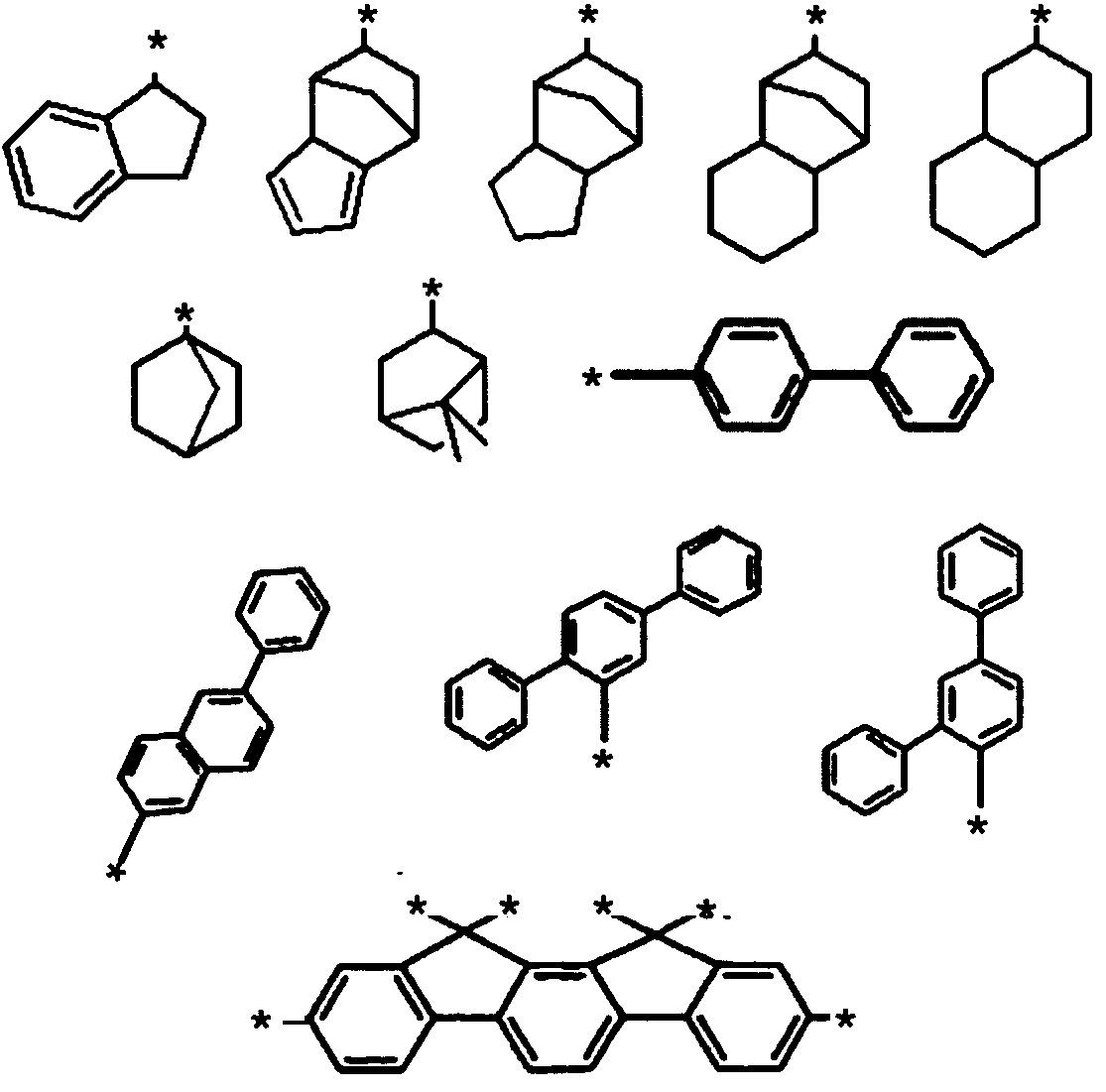
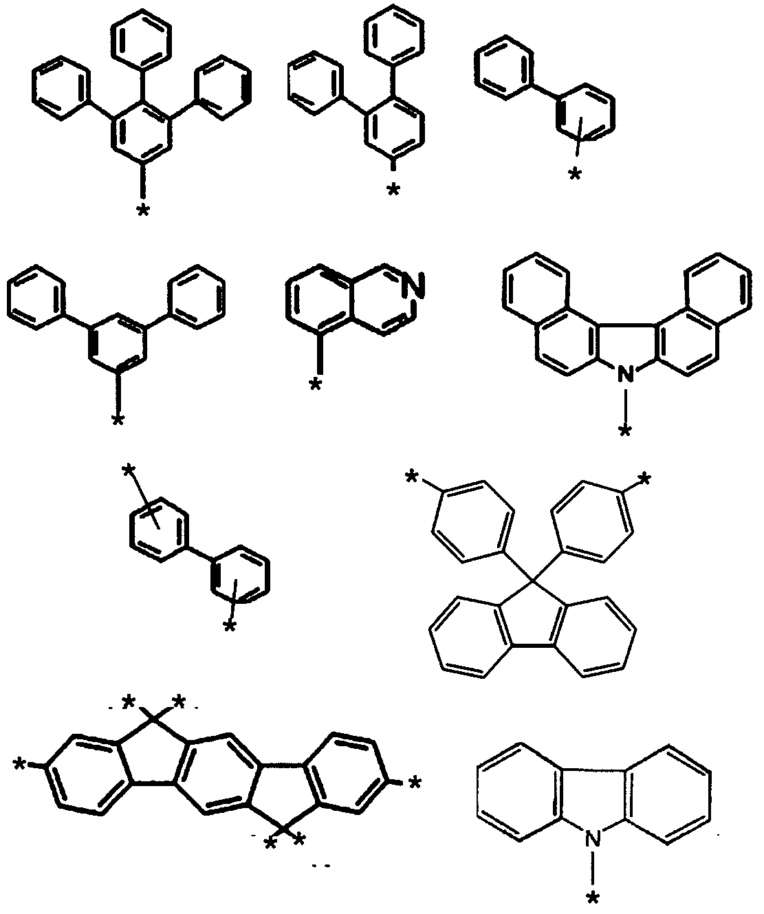

(a)円筒状マスターモールドの作製
円筒状マスターモールドの基材には円筒状の石英ガラスを用い、半導体レーザを用いた直接描画リソグラフィ法により凹凸構造を石英ガラス表面に形成した。まず石英ガラス表面を十二分に洗浄し、パーティクルを除去した。続いて、石英ガラス表面上にスパッタリング法によりレジスト層を成膜した。スパッタリング法は、ターゲット(レジスト層)として、φ3インチのCuO(8atm%Si含有)を用いて、RF100Wの電力で実施し、20nmのレジスト層を成膜した。続いて、石英ガラスを回転させながら、波長405nmnの半導体レーザを用い一度露光を行った。次に、一度露光されたレジスト層に対して、波長405nmn半導体レーザを用いて、露光を行った。この時の露光パタンにより、凹凸構造の配列を制御した。次に、露光後のレジスト層を現像した。現像は、0.03wt%のグリシン水溶液を用いて、240秒間処理とした。次に、現像したレジスト層をマスクとし、ドライエッチングによるエッチング層(石英ガラス)のエッチングを行った。ドライエッチングは、エッチングガスとしてSF6を用い、処理ガス圧1Pa、処理電力300Wの条件で実施した。処理時間を変化させることで、凹凸構造の開口部の大きさ及び凹凸構造の深さを調整した。次に、表面に凹凸構造が付与された石英ガラスから、レジスト層残渣のみを、pH1の塩酸を用いて除去し、円筒状マスターモールドを得た。除去時間は6分間とした。
作製した円筒状マスターモールドを鋳型とし、光ナノインプリント法を適用し、連続的にキャリアを作製した。キャリアを構成する原料としては、以下の材料1を使用した。
材料1…フッ素含有ウレタン(メタ)アクリレート(OPTOOL(登録商標) DAC HP(ダイキン工業社製)):トリメチロールプロパン(EO変性)トリアクリレート(M350(東亞合成社製)):1-ヒドロキシシクロヘキシルフェニルケトン(Irgacure(登録商標)184(BASF社製)):2-ベンジル-2-ジメチルアミノ-1-(4-モルフォリノフェニル)-ブタノン-1(Irgacure 369(BASF社製))=17.5g:100g:5.5g:2.0gにて混合した材料
キャリアG2の凹凸構造Ca面に対し、機能塗工液1を塗工し、機能転写体を作製した。
機能塗工液1…ベンジル系バインダ樹脂:ビスフェノールA EO変性ジアクリレート(アロニックス(登録商標)M211B、東亞合成社製):フェノキシエチルアクリレート(ライトアクリレートPO-A、共栄社化学社製):トリメチロールプロパン(EO変性)トリアクリレート(アロニックスM350、東亞合成社製):1-ヒドロキシ-シクロヘキシル-フェニル-ケトン(Irgacure 184、BASF社製):2-ベンジル-2-ジメチルアミノ-1-(4-モルフォリノフェニル)-ブタノン-1(Irgacure 369、BASF社製)=150g:40g:40g:20g:11g:4gで混合した組成物を、メチルエチルケトン及びプロピレングリコールモノメチルエーテルの混合溶剤にて10質量%に希釈した材料。ベンジル系バインダ樹脂は、ベンジルメタクリレート80質量%、メタクリル酸20質量%の2元共重合体のメチルエチルケトン溶液(固形分50%、重量平均分子量56000、酸当量430、分散度2.7)を使用した。なお、上記質量は固形分質量で記載した。
機能転写体の保護層を剥がし、キャリアG2上の機能層表面を光学顕微鏡により250倍の倍率で、株式会社キーエンス社製のレーザーマイクロスコープVK-9510を使用し観察した。任意の1mm×1mm範囲の中の直径1μm以上の穴欠陥を数え、任意の10カ所の平均数から、1cm×1cm範囲の中の穴数を算出した。メカニズムは不明だが、穴欠陥が1000個未満の場合、被処理体への機能層転写性が飛躍的に向上するため、1000個未満を良しとし、下記の基準より評価を行った。
◎:穴欠陥10個未満
○:穴欠陥10個以上100個未満
△:穴欠陥100個以上1000個未満
×:穴欠陥1000個以上
機能転写体を使用することで、被処理体上に機能層を転写付与し、続けて、転写付与された機能層を加工マスクとして機能させ、被処理体を加工した。
実施例1の機能塗工液のダイコータで塗工する際の塗工圧を所望の膜厚になるように変える以外は実施例1と同様な手法で評価を行った。
実施例1の保護層をフィルムB(ポリエチレン/ポリオレフィンコポリマの共押出フィルム、PAC-3J-30H、厚み30μm、サンエー化研社製)に変え、ポリオレフィンコポリマの側を機能層と接する面にして、ラミネートロールを通して巻き取った。また、樹脂塗工液をダイコータで塗工する際の塗工圧を所望の膜厚になるように変える以外は実施例1と同様な手法で評価を行った。フィルムBのポリオレピンコポリマ面のRqは45nmであった。
実施例1の保護層をフィルムC(ポリエチレンフィルム、GF-858、33μm、タマポリ社製)に変え、また、樹脂塗工液をダイコータで塗工する際の塗工圧を所望の膜厚になるように変える以外は実施例1と同様な手法で評価を行った。フィルムCのRqは94nmであった。
実施例1の保護層をフィルムD(ポリプロピレン二軸延伸フィルム、E-200A、厚み20μm、王子エフテックス社製)に変え、また、樹脂塗工液をダイコータで塗工する際の塗工圧を所望の膜厚になるように変える以外は実施例1と同様な手法で評価を行った。フィルムDのRqは60nmであった。
実施例1の保護層をフィルムE(ポリカーボネートフィルム、100FE2000、厚み100μm、三菱エンジニアリングプラスチック社製)に変え、また、樹脂塗工液をダイコータで塗工する際の塗工圧を所望の膜厚になるように変える以外は実施例1と同様な手法で評価を行った。フィルムEのRqは33nmであった。フィルムEの場合は、機能層と保護層との間にエアー噛みの部分があり、きれいに巻きとることが難しかった。また、機能層から剥離する際、機能層に保護層の成分が残存する部分がみられた。エアー噛み及び保護層残存成分がない部分を用いて、穴欠陥の評価を行った。


実施例1~実施例35の結果より、比率(Rq/t)を満たす機能転写体の構成を達成することで、比率(Ra/t)を制御可能であり、これにより、良好な機能層の転写が可能であることがわかった。実施例36においては、機能層の配置が変化した場合であっても、比率(Rq/t)の効果が発現するか否かを調査した。
実施例1と同様に行った。但し、凹凸構造の平均ピッチ及び配列を半導体レーザの露光パルスにより、凹凸構造の形状をドライエッチングの時間により制御した。また、円筒状マスターモールドに対する離型処理は、以下のように行った。まず、円筒状マスターモールドを回転させた状態にて、フッ素系表面処理剤(デュラサーフHD-2100Z、ダイキン化学工業社製)を塗布し、室温にて2時間乾燥した。続いて、円筒状マスターモールドを回転させた状態にて、洗浄剤(デュラサーフHD-ZV、ダイキン化学工業社製)で洗浄した。
実施例1と同様に、キャリアG2を作製した。但し、材料1を、フッ素含有ウレタン(メタ)アクリレート(OPTOOL DAC HP(ダイキン工業社製)):トリメチロールプロパン(EO変性)トリアクリレート(M350(東亞合成社製)):1-ヒドロキシシクロヘキシルフェニルケトン(Irgacure 184(BASF社製)):2-ベンジル-2-ジメチルアミノ-1-(4-モルフォリノフェニル)-ブタノン-1(Irgacure 369(BASF社製))=1.5g~20g:100g:5.5g:2.0gにて混合した材料へと変更した。キャリアG1とキャリアG2と、は同じ組成物を使用し作製した。ここで、フッ素含有ウレタン(メタ)アクリレートの分量を調整することで、キャリアG2の表面自由エネルギーを調整した。より具体的には、キャリアG2の水に対する接触角及び機能層を塗工する際に使用する溶剤の1つであるプロピレングリコールモノメチルエーテルに対する接触角を調整した。また、キャリアG1及びキャリアG2を作製する際の上記材料の膜厚は、3μmとした。
作製したキャリアG2の凹凸構造Ca面上に少なくとも1以上の機能層を成膜することで、機能転写体A1~A5を作製した。作製した機能転写体A1~A5における、キャリアG2と機能層との関係、及びキャリアG2の物性を表3に記載した。なお、キャリアG2に関し、X線電子分光法により測定される表層フッ素元素濃度(Es)と材料1の硬化物の平均フッ素元素濃度(Eb)と、の比率(Es/Eb)は、機能転写体A1~機能転写体A5の順に、75.5,44,41,149及び721であった。また、表3に記載の用語の意味は以下の通りである。
・機能転写体…機能転写体A1~A5のいずれか。
・平均ピッチ…キャリアG2の凹凸構造Caの平均ピッチであり、ディメンジョンはナノメートル。
・平均開口径…キャリアG2の凹凸構造Caの平均開口径であり、ディメンジョンはナノメートル。
・Mcv…キャリアG2の凹凸構造Caの凸部頂部幅であり、ディメンジョンはナノメートル。
・Mcc…キャリアG2の凹凸構造Caの凹部開口幅であり、ディメンジョンはナノメートル。
・Sh/Scm…キャリアG2の凹凸構造Caの開口率であり、無次元値。
・Mcv/Mcc…上記McvとMccと、の比率であり無次元値。
・ΘH2O…キャリアG2の凹凸構造Ca面側に対する水滴の接触角であり、ディメンジョンは度。
・Θpgme…キャリアG2の凹凸構造Ca面側に対するプロピレングリコールモノメチルエーテルの接触角であり、ディメンジョンは度。なお、プロピレングリコールモノメチルエーテルは、機能層をキャリアG2の凹凸構造Ca面に塗工する際に使用した溶剤の1つである。
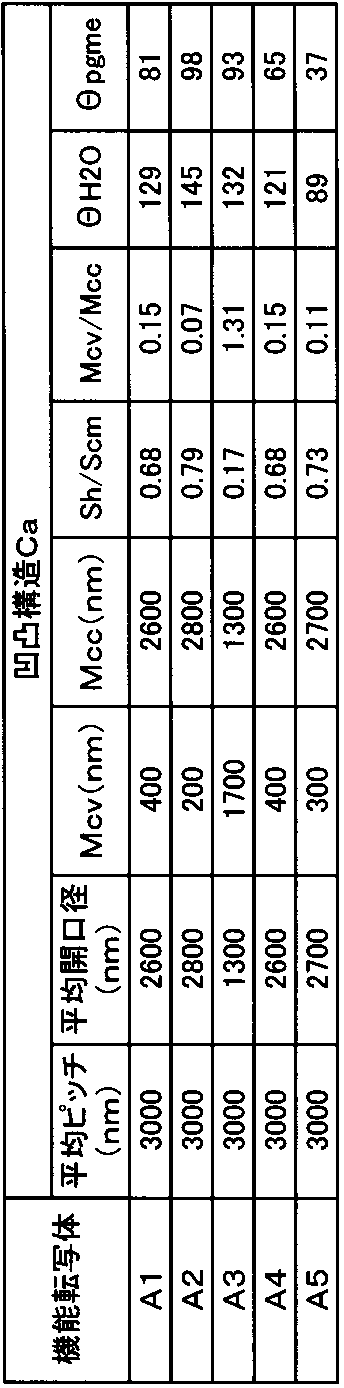
機能転写体A1は、キャリアG2の凹凸構造Caが平坦化するように、1層の機能層を設けた場合であり、実施例1~実施例35にて検討した機能転写体である。キャリアG2の凹凸構造Ca面上に、下記組成物A-1を塗工した。なお、塗工方法は、バーコート法を採用した。バーコート法にて塗工する際に、組成物A-1をプロピレングリコールモノメチルエーテル、アセトン及び2-プロパノールの混合溶剤にて希釈した。希釈濃度は5.2重量%~20重量%の間で変化させ、速度50mm/sec.にて塗工した。即ち、希釈濃度により機能層の膜厚に相当する距離(t)を制御した。塗工後、105℃の乾燥炉の中で15分間静置した。乾燥炉から取り出した後の機能層は非液体状態であり、タック性を示さなかった。即ち、温度20℃で、且つ、遮光下にて非液体状態であることが確認された。また、温度を徐々に上げたところ、60℃近辺からタック性が発現することが確認できた。続いて、機能層の表面に保護層をラミネータにて貼り合わせた。保護層としては、二乗平均平方根高さ(Rq)が異なるものを採用した。具体的には、円筒状マスターモールドのパタンピッチ、パタン深さ、そしてパタンの開口径を変化させることで、キャリアG1の二乗平均平方根高さ(Rq)を制御した。この制御された二乗平均平方根高さ(Rq)を有するキャリアG1を保護層として使用した。
下記環状部位(A)を含むバインダ樹脂と下記環状部位(B)を含むモノマと、を混合した組成物。
・バインダ樹脂:クレゾールノボラック系エポキシアクリレートであり、アクリレート変性率は略100%。下記環状部位(A)を繰り返し単位としており、繰り返し単位数nが0~6まで含まれるホモオリゴマ。平均分子量は約1200である。なお、繰り返しは、CH2の炭素元素に結合する「*」及び6員環に結合する「*」にて繰り返される。
・モノマ:フルオレン骨格を含む下記環状部位(B)を有すモノマ。分子量は546であり、2官能の光重合性モノマである。光重合性基はアクリロイル基である。
・バインダ樹脂とモノマとの混合比率は、重量部にて4.8:5.2とした。なお、光重合開始剤として、αアミノアルキルフェノン系の2-(ジメチルアミノ)-2-[(4-メチルフェニル)メチル]-1-[4-(4-モルホリニル)フェニル]-1-ブタノン(Irgacure 379EG、BASF社製)を選定し、バインダ樹脂とモノマの総量に対して3.49重量%になるように添加した。

機能転写体A2は、キャリアG2の凹凸構造Caの凹部内部に第1の機能層が設けられ、第1の機能層及び凹凸構造Caを平坦化するように第2の機能層を設けた場合である。まず、キャリアG2の凹凸構造Ca面上に、下記組成物A-2を塗工した。なお、塗工方法は、バーコート法を採用した。バーコート法にて塗工する際に、組成物A-2をプロピレングリコールモノメチルエーテル及びアセトンの混合溶剤にて希釈した。希釈濃度は13重量%とし、速度25mm/sec.にて塗工した。塗工後、105℃の乾燥炉の中で10分間静置した。その後、同様の塗工を3度繰り返し行った。第1の機能層のキャリアG2に対する配置をSEM及びTEMにて確認した。第1の機能層はキャリアG2の凹凸構造Caの凹部内部に充填配置されていた。充填量は、第1の機能層の厚みとして1.8μmであった。なお、キャリアG2の凹凸構造Caの深さは2.5μmであった。また、キャリアG2の凹凸構造Caの凸部頂部上には第1の機能層は配置されていなかった。
・組成物A-2
チタニウムテトラブトキシド,テトラマー(和光純薬工業社製):チタニウムテトラブトキシド,モノマ(和光純薬工業社製):3アクリロキシプロピルトリメトキシシラン(信越シリコーン社製):フェニル変性シリコーン(東レ・ダウコーニング社製):光重合開始剤=35.86g:29.34g:34.8g:5.0g:2.6gにて混合した材料。なお、光重合開始剤として、α-ヒドロキシアルキルフェノン系の1-ヒドロキシ-シクロヘキシル-フェニル-ケトン(Irgacure 184、BASF社製)と、α-アミノアルキルフェノン系の、2-ベンジル-2-ジメチルアミノ-1-(4-モルフォリノフェニル)-ブタノン-1(Irgacure 369、BASF社製)を選定し、Irgacure 184:Irgacure 369=2.75:1の比率にて混合した。
機能転写体A3は、キャリアG2の凹凸構造Caの凸部頂部上に第1の機能層が設けられ、第1の機能層及び凹凸構造Caを平坦化するように第2の機能層を設けた場合である。まず、第1の機能層としては、上記組成物A-2を選定した。上記組成物A-2を、プロピレングリコールモノメチルエーテルにて25重量%に希釈し、ポリエチレンテレフタレートフィルム上に、バーコート法により塗工した。塗工後、24℃の環境下にて2分間静置した。
機能転写体A4は、キャリアG2の凹凸構造Caの凹部内部及び凸部頂部上に互いに隔離された第1の機能層が設けられ、第1の機能層及び凹凸構造Caを平坦化するように第2の機能層を設けた場合である。まず、キャリアG2の凹凸構造Ca面上に、上記組成物A-2を、機能転写体A2と同様にして塗工した。塗工後、105℃の乾燥炉の中で10分間静置した。第1の機能層のキャリアG2に対する配置をSEM及びTEMにて確認した。第1の機能層はキャリアG2の凹凸構造Caの凹部内部に充填配置され、且つ、凸部頂部上に配置されていた。また、凹部内部の第1の機能層と、凸部頂部上の第1の機能層と、は互いに離間していた。凹部内部に対する充填量は、第1の機能層の厚みとして1.5μmであった。凸部頂部上に配置された第1の機能層の厚みは、120nm程度であった。また、凸部頂部上に配置された第1の機能層は、キャリアG2の凹凸構造Caの凸部頂部上に均等な膜を形成するのではなく、凸部頂部上に複数のナノ粒子を形成し配置されていた。なお、キャリアG2の凹凸構造Caの深さは2.2μmであった。
機能転写体A5は、キャリアG2の凹凸構造Caの表面を被覆するように第1の機能層が設けられ、第1の機能層を平坦化するように第2の機能層を設けた場合である。まず、キャリアG2の凹凸構造Ca面上に、上記組成物A-2を、機能転写体A2と同様にして塗工した。塗工後、105℃の乾燥炉の中で10分間静置した。第1の機能層のキャリアG2に対する配置をSEM及びTEMにて確認した。第1の機能層はキャリアG2の凹凸構造Caを被覆するように配置されていた。また、キャリアG2の凹部付近の第1の機能層の膜厚は、キャリアG2の凹凸構造Caの凸部近傍の第1の機能層の膜厚よりも厚く成膜されていた。より具体的には、キャリアG2の凹凸構造Caの凹部底部を基準とした際の第1の機能層の膜厚は1.4μmであり、キャリアG2の凹凸構造Caの凸部頂部を基準とした第1の機能層の膜厚は100nmであった。なお、キャリアG2の凹凸構造Caの深さは2.3μmであった。
機能転写体A1~A5の機能層の転写精度を評価した。被処理体として6インチのC面サファイア(オフ角0.2°)を使用した。まず、被処理体を、硫酸及び過酸化水素水を2:1の重量比にて混合した表面処理液の中に15分間浸漬させた。続いて、被処理体を取り出し、超純水を使用し当該表面処理液を洗い流した。最後に、スピン乾燥を行った。表面処理を施した被処理体を120℃のホットプレート上に配置し、この状態にて機能転写体A1~A5をラミネーションした。機能転写体の貼り合わせられた被処理体に対して、機能転写体側より高圧水銀灯光源を用いてUV光を照射した。UV光の積算光量は990mJ/cm2になるように調整した。続いて、機能転写体が貼り合わせられた被処理体を120℃のホットプレート上に90秒間置き、その後10秒間エアーブローを行い冷却した。冷却後、キャリアG2を剥離除去した。
・評価指標
◎+…剥離速度Vm比が4.5以上、且つ欠陥率が、0.5%以下。
◎…剥離速度Vm比が4.5以上、且つ欠陥率が、0.5%超1%以下。
〇+…剥離速度Vm比が4.3以上4.5未満、且つ欠陥率が1%以下。
〇…剥離速度Vm比が3.8以上4.3未満、且つ欠陥率が1.5%以下。
△+…剥離速度Vm比が2.2以上4.3未満、且つ欠陥率が2.5%以下。
△…剥離速度Vm比が1.0以上2.2未満、且つ欠陥率が5%以下。
×…比率(Ra/t)が1.2超の場合。

次に、機能転写体A1~A5の機能層を、加工マスクとして機能させ、被処理体を加工した。ここでは、被処理体として6インチφのC面サファイアを使用した。なお、機能転写体としては、比率(Rq/t)が0.29以下のものを使用した。
機能層付被処理体の機能層面側から、酸素ガス使用したリアクティブイオンエッチングを行い、被処理体表面を部分的に露出させた。エッチンング条件は、圧力1Pa、電力300Wとし、被処理体の表面が部分的に露出するまでの時間を調整した。
上記「機能転写体の評価」と同様の操作を行い、被処理体上に機能層を転写付与した。機能層付被処理体の機能層面側から、上記「機能転写体A1の使用」と同様に酸素ガス使用したエッチングを行い、被処理体表面を部分的に露出させた。なお、被処理体の表面が部分的に露出するまでの時間を調整した。エッチング後の機能層をSEMにて観察したところ、第1の機能層の体積は殆ど減少しておらず、第2の機能層のみが加工されていることが確認された。即ち、第1の機能層は、第2の機能層の加工用マスクとして機能していた。
上記「機能転写体の評価」と同様の操作を行い、被処理体上に機能層を転写付与した。機能層付被処理体の機能層面側から、上記「機能転写体A1の使用」と同様に酸素ガスを使用したエッチングを行い、被処理体表面を部分的に露出させた。なお、被処理体の表面が部分的に露出するまでの時間を調整した。エッチング後の機能層をSEMにて観察したところ、第1の機能層の体積は殆ど減少しておらず、第2の機能層が加工されていることが確認された。即ち、第1の機能層は、第2の機能層の加工用マスクとして機能していた。
上記「機能転写体の評価」と同様の操作を行い、被処理体上に機能層を転写付与した。機能層付被処理体の機能層面側から、上記「機能転写体A1の使用」と同様に酸素ガスを使用したエッチングを行い、被処理体表面を部分的に露出させた。なお、被処理体の表面が部分的に露出するまでの時間を調整した。エッチング後の機能層をSEMにて観察したところ、第1の機能層の体積は殆ど減少しておらず、第2の機能層が加工されていることが確認された。即ち、第1の機能層は、第2の機能層の加工用マスクとして機能していた。また、被処理体上には径の大きな第2の機能層のパタンと、径の小さな第2の機能層のパタンが形成されていた。この径の小さな第2の機能層のパタンは、機能転写体A4の凹凸構造Caの凸部の頂部上に配置された第1の機能層に由来する。より具体的には、径の大きな第2の機能層のパタンは六方配列にて配列しており、六方配列する径の大きな第2の機能層の互いに隣接する凸部の間に、径の小さな第2の機能層が設けられていた。
上記「機能転写体の評価」と同様の操作を行い、被処理体上に機能層を転写付与した。機能層付被処理体の機能層面側から、上記「機能転写体A1の使用」と同様に、酸素ガスを使用したエッチングを行い、被処理体表面を部分的に露出させた。なお、被処理体の表面が部分的に露出するまでの時間を調整した。エッチング後の機能層をSEMにて観察したところ、機能転写体の凹凸構造Caの凸部上に位置する第1の機能層被膜に相当する部分は除去され、凹凸構造Caの凹部内壁に被膜を形成した第1の機能層が残っていた。また、凹凸構造Caの凹部内壁に被膜を形成した第1の機能層の下に配置される第2の機能層は残っており、凹凸構造Caの凸部上に位置する第1の機能層被膜下に位置する第2の機能層は除去されていた。即ち、第1の機能層は、第2の機能層の加工用マスクとして機能していた。
実施例37においては、機能転写体の機能層の最外層の物性と被処理体の種類の与える、転写性への影響と、を調査した。ここでは、実施例36より、機能転写体における機能層の配置は転写性に影響しないことがわかっているため、実施例36の機能転写体A1を代表し、使用した。


下記の繰り返し単位(a)と繰り返し単位(b)とから構成される共重合ポリマである。分子量は2900である。繰り返し単位bの繰り返し数Nbと繰り返し単位aの繰り返し単位Naと、の比率(Nb/Na)は0.25である。

下記の繰り返し単位(c)を含むクレゾールノボラック系エポキシアクリレートであり、アクリレート置換率は略100%である。繰り返し単位数nが0~6まで含まれるホモオリゴマである。平均分子量は約1200である。なお、繰り返しは、CH2の炭素元素に結合する「*」及び6員環に結合する「*」にて繰り返される。また、光重合開始剤として、αアミノアルキルフェノン系の2-(ジメチルアミノ)-2-[(4-メチルフェニル)メチル]-1-[4-(4-モルホリニル)フェニル]-1-ブタノン(Irgacure 379EG、BASF社製)を3.17重量%添加した。
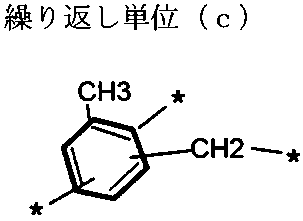
上記繰り返し単位(a)と下記繰り返し単位(d)と、から構成される共重合ポリマである。平均分子量は5500であり、繰り返し単位(a)の繰り返し数Naと繰り返し単位(d)の繰り返しNdとの比率(Na/Nd)は1.5である。なお、光重合開始剤として、オキシムエステル系のエタノン,1-[9-エチル-6-(2-メチルベンゾイル)-9H-カルバゾール-3-イル]-,1-(0-アセチルオキシム)(Irgacure OXE02、BASF社製)を4.2重量%添加した。
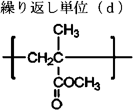
クレゾールノボラック系エポキシメタアクリレートであり、メタアクリレート変性率は約50%のホモポリマである。分子量は約3000である。光重合開始剤として、α-ヒドロキシアルキルフェノン系の1-ヒドロキシ-シクロヘキシル-フェニル-ケトン(Irgacure 184、BASF社製)と、α-アミノアルキルフェノン系の、2-ベンジル-2-ジメチルアミノ-1-(4-モルフォリノフェニル)-ブタノン-1(Irgacure 369、BASF社製)を選定し、Irgacure 184:Irgacure 369=2.75:1の比率にて混合し、3.18重量%添加した。
フェノールノボラック系エポキシメタアクリレートであり、メタアクリレート変性率は約50%のホモポリマである。分子量は約3000である。光重合開始剤として、α-ヒドロキシアルキルフェノン系の1-ヒドロキシ-シクロヘキシル-フェニル-ケトン(Irgacure 184、BASF社製)と、α-アミノアルキルフェノン系の、2-ベンジル-2-ジメチルアミノ-1-(4-モルフォリノフェニル)-ブタノン-1(Irgacure 369、BASF社製)を選定し、Irgacure 184:Irgacure 369=2.75:1の比率にて混合し、3.18重量%添加した。
下記繰り返し単位(e)を有すポリエチレングリコールであり、分子量は約40000である。なお、末端は水酸基である。
(繰り返し単位(e))
-(CH2-CH2-O)n-
上記繰り返し単位(a)と下記繰り返し単位(f)と、から構成されるアミノエチル化共重合アクリルポリマである。平均分子量は約20000であり、繰り返し単位(a)の繰り返し数Naと繰り返し単位(f)の繰り返し数Nfとの比率(Na/Nf)は0.67である。
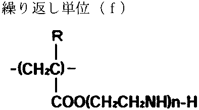
組成物B-1に記載の共重合ポリマに対して、モノマであるトリシクロデカンジメタノールジアクリレート及びトリス(2-ヒドロキシエチル)イソシアヌレートトリアクリレートを混合した材料である。なお、ポリマの総重量とモノマの総重量との比は、5.5:4.5とした。また、モノマ総重量に対して5.5重量%の光重合開始剤を添加した。光重合開始剤として、α-ヒドロキシアルキルフェノン系の1-ヒドロキシ-シクロヘキシル-フェニル-ケトン(Irgacure 184、BASF社製)と、α-アミノアルキルフェノン系の2-ベンジル-2-ジメチルアミノ-1-(4-モルフォリノフェニル)-ブタノン-1(Irgacure 369、BASF社製)を選定し、Irgacure 184:Irgacure 369=2.75:1の比率にて混合した。
組成物B-2に記載のクレゾールノボラック系エポキシアクリレートに、モノマであるトリシクロデカンジメタノールジアクリレート及びトリス(2-ヒドロキシエチル)イソシアヌレートトリアクリレートを混合した材料である。なお、ポリマの総重量とモノマの総重量の比とは、7.9:2.1とした。また、オリゴマ及びモノマ総重量に対して5.5重量%の光重合開始剤を添加した。光重合開始剤は、αアミノアルキルフェノン系の2-(ジメチルアミノ)-2-[(4-メチルフェニル)メチル]-1-[4-(4-モルホリニル)フェニル]-1-ブタノン(Irgacure 379 EG、BASF社製)を選定した。
組成物B-3に記載の共重合ポリマに、モノマであるトリシクロデカンジメタノールジアクリレート及びトリス(2-ヒドロキシエチル)イソシアヌレートトリアクリレートを混合した材料である。なお、ポリマの総重量とモノマの総重量との比は、4.2:5.8とした。また、ポリマとモノマの総重量に対して5.5重量%の光重合開始剤を添加した。光重合開始剤は、オキシムエステル系の、エタノン,1-[9-エチル-6-(2-メチルベンゾイル)-9H-カルバゾール-3-イル]-,1-(0-アセチルオキシム)(Irgacure OXE 02、BASF社製)を選定した。
組成物B-4に記載のポリメチルメタアクリレートに、モノマである2-エチルヘキシルEO変性アクリレート及びトリメチロールプロパントリアクリレートを混合した材料である。なお、ポリマの総重量とモノマの総重量との比は、4.0:6.0とした。また、モノマ総重量に対して5.5重量%の光重合開始剤を添加した。光重合開始剤は、α-ヒドロキシアルキルフェノン系の1-ヒドロキシ-シクロヘキシル-フェニル-ケトン(Irgacure 184、BASF社製)と、α-アミノアルキルフェノン系の、2-ベンジル-2-ジメチルアミノ-1-(4-モルフォリノフェニル)-ブタノン-1(Irgacure 369、BASF社製)を選定し、Irgacure 184:Irgacure 369=2.75:1の比率にて混合した。
組成物B-5に記載のフェノールノボラック系エポキシメタアクリレートに、モノマであるトリシクロデカンジメタノールジアクリレート及びトリス(2-ヒドロキシエチル)イソシアヌレートトリアクリレートを混合した材料である。なお、ポリマの総重量とモノマの総重量との比は、8.2:1.8とした。また、ポリマ及びモノマの総重量に対して5.5重量%の光重合開始剤を添加した。光重合開始剤は、α-ヒドロキシアルキルフェノン系の1-ヒドロキシ-シクロヘキシル-フェニル-ケトン(Irgacure 184、BASF社製)と、α-アミノアルキルフェノン系の2-ベンジル-2-ジメチルアミノ-1-(4-モルフォリノフェニル)-ブタノン-1(Irgacure 369、BASF社製)を選定し、Irgacure 184:Irgacure 369=2.75:1の比率にて混合した。
組成物B-6に記載のポリエチレングリコールに、モノマであるトリシクロデカンジメタノールジアクリレート及びトリス(2-ヒドロキシエチル)イソシアヌレートトリアクリレートを混合した材料である。なお、ポリマの総重量とモノマの総重量と比は、5.5:4.5とした。また、モノマ総重量に対して5.5重量%の光重合開始剤を添加した。光重合開始剤は、α-ヒドロキシアルキルフェノン系の1-ヒドロキシ-シクロヘキシル-フェニル-ケトン(Irgacure 184、BASF社製)とα-アミノアルキルフェノン系の2-ベンジル-2-ジメチルアミノ-1-(4-モルフォリノフェニル)-ブタノン-1(Irgacure 369、BASF社製)を選定し、Irgacure 184:Irgacure 369=2.75:1の比率にて混合した。
組成物B-7に記載のアミノエチル化共重合アクリルポリマに、モノマであるトリシクロデカンジメタノールジアクリレート及びトリメチロールプロパンEO変性トリアクリレートを混合した材料である。なお、ポリマの総重量とモノマの総重量と比は、6.7:2.3とした。また、モノマ総重量に対して5.5重量%の光重合開始剤を添加した。光重合開始剤は、オキシムエステル系の、エタノン,1-[9-エチル-6-(2-メチルベンゾイル)-9H-カルバゾール-3-イル]-,1-(0-アセチルオキシム) (Irgacure OXE 02、BASF社製)を選定した。
50℃における粘度が約3000mPa・sのフェニルグリシジルエーテルアクリレートと、25℃における粘度が約25000mPa・sのペンタエリスリトールトリアクリレートヘキサメチレンジイソシアネートウレタンプレポリマと、を重量比にて75:25にて混合した材料に、5.5重量%の光重合開始剤を添加した。光重合開始剤は、αアミノアルキルフェノン系の、2-(ジメチルアミノ)-2-[(4-メチルフェニル)メチル]-1-[4-(4-モルホリニル)フェニル]-1-ブタノン(Irgacure 379 EG、BASF社製)を選定した。
下記繰り返し単位(g)を有すチタンポリマ、側鎖フェニル変性シリコーン(信越シリコーン社製 SH710)、チタニウムテトラブトキシド、3アクリロキシプロピルトリメトキシシラン、及び3-グリシジルオキシプロピルトリメトキシシランを混合した材料であり、混合比率は、1:1.3:1.5:0.42:0.42とした。また、3アクリロキシプロピルトリメトキシシランに対して5.5重量%の光重合開始剤を添加した。光重合開始剤は、αアミノアルキルフェノン系の2-(ジメチルアミノ)-2-[(4-メチルフェニル)メチル]-1-[4-(4-モルホリニル)フェニル]-1-ブタノン(Irgacure 379 EG、BASF社製)を選定した。
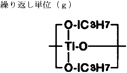
分子量が40000のポリジメチルシロキサン、側鎖フェニル変性シリコーン(信越シリコーン社製 SH710)、チタニウムテトラブトキシド、3アクリロキシプロピルトリメトキシシラン、及び3-グリシジルオキシプロピルトリメトキシシランを混合した材料であり、混合比率は、1:1.3:1.5:0.42:0.42とした。また、3アクリロキシプロピルトリメトキシシランに対して5.5重量%の光重合開始剤を添加した。光重合開始剤は、αアミノアルキルフェノン系の、2-(ジメチルアミノ)-2-[(4-メチルフェニル)メチル]-1-[4-(4-モルホリニル)フェニル]-1-ブタノン(Irgacure 379 EG、BASF社製)を選定した。
組成物B-16に記載したチタンポリマである。
分子量が約40000のポリジメチルシロキサンであり、組成物B-17にて使用したものと同様のものである。
分子量が5800のポリイソプレンである。
分子量が56000のポリスチレンである。
・被処理体T-1… 石英ガラス。
・被処理体T-2… サファイア(C面)。
・被処理体T-3… シリコンカーバイド(SiC)。
・被処理体T-4… 窒化ガリウム。
・被処理体T-5… 金。但し、石英ガラスの表面に金を蒸着し成膜したもの。
・被処理体T-6… 銀。但し、石英ガラスの表面に銀を蒸着し成膜したもの。
・被処理体T-7… 酸化インジウムスズ(ITO)。
・被処理体T-8… ポリエチレンテレフタレート(PET)。
・被処理体T―9… 合成皮革(表皮表層はポリウレタンフィルム)。

実施例38においては、キャリアの物性と機能層の物性の関係の与える転写精度への影響を調査した。実施例36及び実施例37より、比率(Rq/t)が所定の範囲であることで、転写性を良好に保てること、また、機能層の最外層に極性基を含むことで転写性がより良好に保てることがわかっている。このため、実施例38においては、実施例36の機能転写体A1の形態を代表させ、機能層として、実施例36の組成物A-1を使用した機能転写体Cを作製し検討に使用した。ここで、キャリアの物性を変数にした。また、転写対象となる被処理体には、表面物性の大きく異なる被処理体T-2、T-8、T-9、及びT-13を使用した。
・キャリアC-1…実施例36に記載のキャリアG2であり、フッ素含有ウレタン(メタ)アクリレート(OPTOOL DAC HP(ダイキン工業社製))をトリメチロールプロパン(EO変性)トリアクリレート(M350(東亞合成社製))に対して2重量部の添加量にしたものである。水滴の接触角は119度である。比率(Es/Eb)は、119であった。

実施例39においては、凹凸構造Caのピッチがマイクロオーダの領域にある場合に関し、機能転写体の機能層の精度と凹凸構造Fuの転写性とを、同時に改善可能かを調査した。

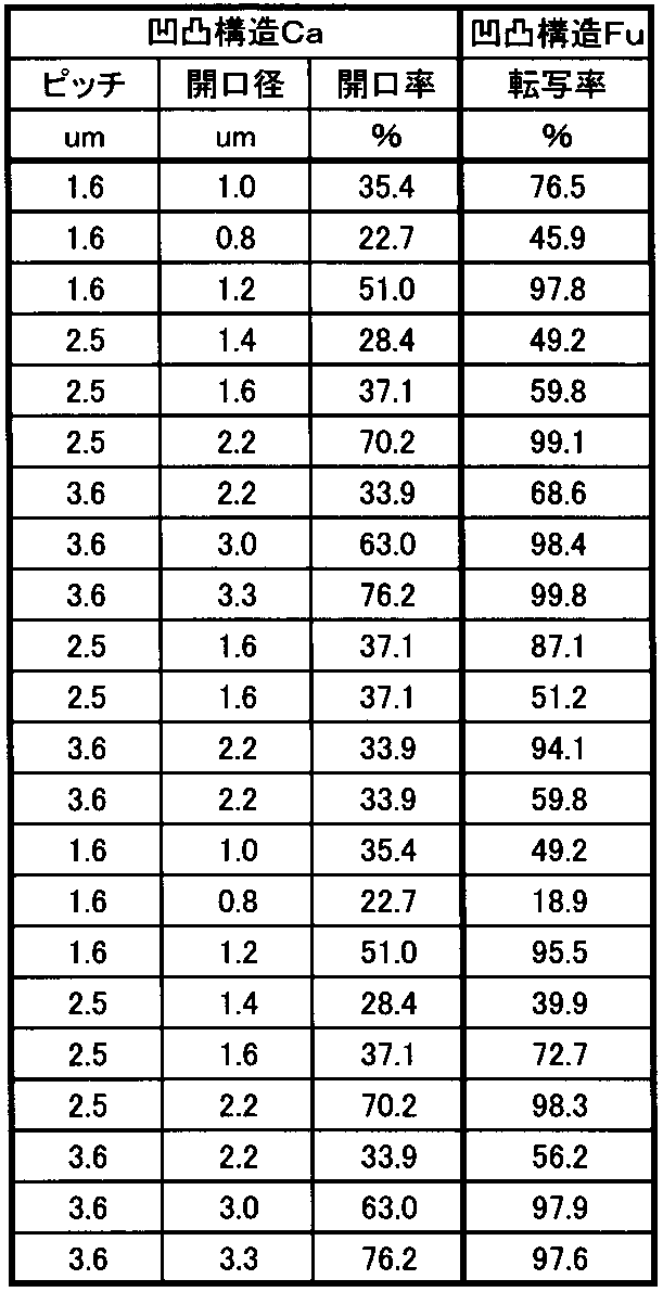
上記実施例より、キャリアのピッチによらず精度の高い機能層を具備する機能転写体を製造し、高い精度で機能層を被処理体に転写できることがわかった。本実施例では、保護層の与える、機能層の穴欠陥への影響を詳細に調査した。
・ポリエチレン/ポリオレフィンコポリマの共押出フィルム(サンエー化研社製 PAC-3-30 30μmt)。引張弾性率は450MPa。
・ポリエチレンフィルム(タマポリ社製 GF-858 33μmt)。引張弾性率は1080MPa。
・ポリカーボネートフィルム(三菱エンジニアリングプラスチック社製 100FE200)。引張弾性率は2400MPa。
・COPフィルム(日本ゼオン社製 ZEONEX(登録商標) F52R)。引張弾性率は3000MPa。
・PETフィルム(東洋紡社製 東洋紡エステル(登録商標)フィルム E5100 25μmt)。引張弾性率は4000MPa。
(凹凸構造Ca)
・配列:六方配列、開口径:1.0μm、1.8μm、2.1μm、2.5μm、3.0μm、10.0μm。
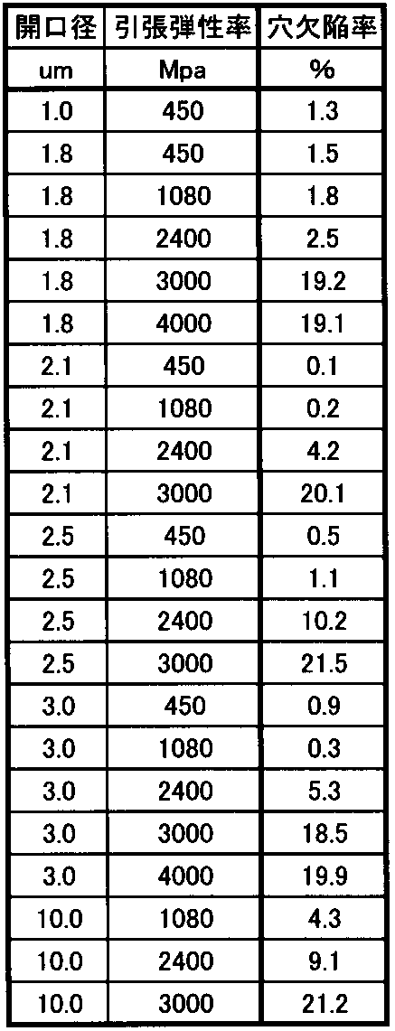
上記実施例より、キャリアのピッチによらず精度の高い機能層を具備する機能転写体を製造し、高い精度で機能層を被処理体に転写できることがわかった。特に、凹凸構造Caの開口径によらずに、保護層の引張弾性率が機能層の穴欠陥に大きく影響することがわかった。更には、ピッチがマイクロメートルオーダの場合は、特に、キャリアの凹凸構造の開口率の制御が重要であることがわかった。以上より、保護層の物性である引張弾性率と凹凸構造Caの開口率と、により、より好適な機能転写体の範囲があると推測できる。実施例41では、保護層の引張弾性率と凹凸構造Caの開口率と、の関係を調査した。

本実施例では、機能転写体を量産製造する場合の製造安定性と、量産使用する際の安定性と、を改善する要素を検討した。

Claims (10)
- 表面に凹凸構造を具備するキャリアと、前記凹凸構造上に設けられた少なくとも1以上の機能層と、前記機能層の前記キャリアとは反対の面上に設けられた保護層と、を具備し、前記機能層は樹脂を含むと共に、前記保護層の前記機能層に接する面側の二乗平均平方根高さ(Rq)と、前記凹凸構造の凸部頂部位置と前記機能層の前記保護層と、の界面までの距離(t)と、の比率(Rq/t)が1.41以下であることを特徴とする機能転写体。
- 前記機能層から前記保護層を剥離したときの、前記機能層の前記保護層に接していた面の表面粗さ(Ra)と前記距離(t)と、の比率(Ra/t)が1.20以下であることを特徴とする請求項1記載の機能転写体。
- 前記キャリアの前記凹凸構造の平均ピッチは1.5μm超10μm以下の範囲であり、且つ、前記凹凸構造の平均開口率は40%以上であることを特徴とする請求項1又は請求項2に記載の機能転写体。
- 前記保護層の引張弾性率は50MPa以上2500MPa以下であることを特徴とする請求項1記載の機能転写体。
- 前記凹凸構造の平均開口率が40%以上であることを特徴とする請求項4記載の機能転写体。
- 前記平均開口率が91%以下であることを特徴とする請求項5記載の機能転写体。
- 前記凹凸構造の凹部開口径は1μm以上10μm以下であることを特徴とする請求項4記載の機能転写体。
- 前記凹凸構造は平面視円形状であることを特徴とする請求項7記載の機能転写体。
- 前記保護層の前記機能層に接する面に対する、水滴の接触角が75度以上105度以下であることを特徴とする請求項1、請求項2、又は請求項4から請求項8のいずれかに記載の機能転写体。
- 請求項1から請求項9のいずれかに記載の機能転写体がフィルム状であり、前記機能転写体の一端部がコアに接続され、且つ、前記機能転写体が前記コアに巻き取られたことを特徴とする機能転写フィルムロール。
Priority Applications (3)
| Application Number | Priority Date | Filing Date | Title |
|---|---|---|---|
| JP2016514843A JP6171089B2 (ja) | 2014-04-25 | 2015-04-06 | 機能転写体及び機能転写フィルムロール |
| KR1020167027877A KR101843678B1 (ko) | 2014-04-25 | 2015-04-06 | 기능 전사체 및 기능 전사 필름 롤 |
| CN201580022071.4A CN106256015B (zh) | 2014-04-25 | 2015-04-06 | 功能转印体以及功能转印膜辊 |
Applications Claiming Priority (4)
| Application Number | Priority Date | Filing Date | Title |
|---|---|---|---|
| JP2014-091895 | 2014-04-25 | ||
| JP2014091895 | 2014-04-25 | ||
| JP2015-007165 | 2015-01-16 | ||
| JP2015007165 | 2015-01-16 |
Publications (1)
| Publication Number | Publication Date |
|---|---|
| WO2015163129A1 true WO2015163129A1 (ja) | 2015-10-29 |
Family
ID=54332296
Family Applications (1)
| Application Number | Title | Priority Date | Filing Date |
|---|---|---|---|
| PCT/JP2015/060749 Ceased WO2015163129A1 (ja) | 2014-04-25 | 2015-04-06 | 機能転写体及び機能転写フィルムロール |
Country Status (5)
| Country | Link |
|---|---|
| JP (1) | JP6171089B2 (ja) |
| KR (1) | KR101843678B1 (ja) |
| CN (1) | CN106256015B (ja) |
| TW (1) | TWI618113B (ja) |
| WO (1) | WO2015163129A1 (ja) |
Cited By (10)
| Publication number | Priority date | Publication date | Assignee | Title |
|---|---|---|---|---|
| JP2018003173A (ja) * | 2016-06-28 | 2018-01-11 | 大日本印刷株式会社 | 離型シート及び樹脂皮革 |
| JP2018024110A (ja) * | 2016-08-08 | 2018-02-15 | 大日本印刷株式会社 | 転写シート、転写シートの製造方法、及び加飾成形品の製造方法 |
| WO2018030334A1 (ja) * | 2016-08-08 | 2018-02-15 | 大日本印刷株式会社 | 転写シート、転写シートの製造方法、及び加飾成形品の製造方法 |
| JP2018034495A (ja) * | 2016-08-30 | 2018-03-08 | 大日本印刷株式会社 | 転写シート、転写シートの製造方法、及び加飾成形品の製造方法 |
| JP2018176689A (ja) * | 2017-04-21 | 2018-11-15 | 大日本印刷株式会社 | 転写シート、転写シートの製造方法及び加飾成形品の製造方法 |
| JP2019030993A (ja) * | 2017-08-07 | 2019-02-28 | 大日本印刷株式会社 | 転写シート、転写シートの製造方法及び加飾成形品の製造方法 |
| JP2019171838A (ja) * | 2018-03-29 | 2019-10-10 | 東レ株式会社 | 積層体 |
| US20210186652A1 (en) * | 2018-09-20 | 2021-06-24 | Toppan Printing Co., Ltd. | Examination marker |
| WO2023084082A1 (en) * | 2021-11-15 | 2023-05-19 | Morphotonics Holding B.V. | Multi-textured stamp |
| US20250123556A1 (en) * | 2022-01-17 | 2025-04-17 | Morphotonics Holding B.V. | Composite Article and Method for Manufacturing a Composite Article |
Families Citing this family (1)
| Publication number | Priority date | Publication date | Assignee | Title |
|---|---|---|---|---|
| CN109649031B (zh) * | 2018-11-19 | 2021-02-05 | 江苏学泰印务有限公司 | 一种多层叠放式无套印边转印膜 |
Citations (3)
| Publication number | Priority date | Publication date | Assignee | Title |
|---|---|---|---|---|
| JP2011165855A (ja) * | 2010-02-09 | 2011-08-25 | Toshiba Corp | パターン形成方法 |
| JP5466795B1 (ja) * | 2012-06-13 | 2014-04-09 | 旭化成イーマテリアルズ株式会社 | 機能転写体、機能層の転写方法、梱包物及び機能転写フィルムロール |
| JP2014065219A (ja) * | 2012-09-26 | 2014-04-17 | Shin Etsu Polymer Co Ltd | 離型用フィルム |
Family Cites Families (4)
| Publication number | Priority date | Publication date | Assignee | Title |
|---|---|---|---|---|
| KR101016826B1 (ko) * | 2009-02-13 | 2011-02-21 | 주식회사 하이닉스반도체 | 반도체 소자의 패턴 및 이의 형성 방법 |
| JP2011066100A (ja) * | 2009-09-16 | 2011-03-31 | Bridgestone Corp | 光硬化性転写シート、及びこれを用いた凹凸パターンの形成方法 |
| JP2011216647A (ja) * | 2010-03-31 | 2011-10-27 | Dainippon Printing Co Ltd | パターン形成体の製造方法、機能性素子の製造方法および半導体素子の製造方法 |
| TWI432523B (zh) * | 2011-06-21 | 2014-04-01 | Asahi Kasei E Materials Corp | And an inorganic composition for transfer of fine asperity structure |
-
2015
- 2015-04-06 JP JP2016514843A patent/JP6171089B2/ja not_active Expired - Fee Related
- 2015-04-06 CN CN201580022071.4A patent/CN106256015B/zh not_active Expired - Fee Related
- 2015-04-06 WO PCT/JP2015/060749 patent/WO2015163129A1/ja not_active Ceased
- 2015-04-06 KR KR1020167027877A patent/KR101843678B1/ko not_active Expired - Fee Related
- 2015-04-17 TW TW104112474A patent/TWI618113B/zh not_active IP Right Cessation
Patent Citations (3)
| Publication number | Priority date | Publication date | Assignee | Title |
|---|---|---|---|---|
| JP2011165855A (ja) * | 2010-02-09 | 2011-08-25 | Toshiba Corp | パターン形成方法 |
| JP5466795B1 (ja) * | 2012-06-13 | 2014-04-09 | 旭化成イーマテリアルズ株式会社 | 機能転写体、機能層の転写方法、梱包物及び機能転写フィルムロール |
| JP2014065219A (ja) * | 2012-09-26 | 2014-04-17 | Shin Etsu Polymer Co Ltd | 離型用フィルム |
Cited By (12)
| Publication number | Priority date | Publication date | Assignee | Title |
|---|---|---|---|---|
| JP2018003173A (ja) * | 2016-06-28 | 2018-01-11 | 大日本印刷株式会社 | 離型シート及び樹脂皮革 |
| JP2018024110A (ja) * | 2016-08-08 | 2018-02-15 | 大日本印刷株式会社 | 転写シート、転写シートの製造方法、及び加飾成形品の製造方法 |
| WO2018030334A1 (ja) * | 2016-08-08 | 2018-02-15 | 大日本印刷株式会社 | 転写シート、転写シートの製造方法、及び加飾成形品の製造方法 |
| JP2018034495A (ja) * | 2016-08-30 | 2018-03-08 | 大日本印刷株式会社 | 転写シート、転写シートの製造方法、及び加飾成形品の製造方法 |
| JP2018176689A (ja) * | 2017-04-21 | 2018-11-15 | 大日本印刷株式会社 | 転写シート、転写シートの製造方法及び加飾成形品の製造方法 |
| JP2019030993A (ja) * | 2017-08-07 | 2019-02-28 | 大日本印刷株式会社 | 転写シート、転写シートの製造方法及び加飾成形品の製造方法 |
| JP2019171838A (ja) * | 2018-03-29 | 2019-10-10 | 東レ株式会社 | 積層体 |
| JP7200562B2 (ja) | 2018-03-29 | 2023-01-10 | 東レ株式会社 | 積層体 |
| US20210186652A1 (en) * | 2018-09-20 | 2021-06-24 | Toppan Printing Co., Ltd. | Examination marker |
| US12551314B2 (en) * | 2018-09-20 | 2026-02-17 | Toppan Printing Co., Ltd. | Examination marker |
| WO2023084082A1 (en) * | 2021-11-15 | 2023-05-19 | Morphotonics Holding B.V. | Multi-textured stamp |
| US20250123556A1 (en) * | 2022-01-17 | 2025-04-17 | Morphotonics Holding B.V. | Composite Article and Method for Manufacturing a Composite Article |
Also Published As
| Publication number | Publication date |
|---|---|
| JPWO2015163129A1 (ja) | 2017-04-13 |
| TW201604033A (zh) | 2016-02-01 |
| JP6171089B2 (ja) | 2017-07-26 |
| CN106256015A (zh) | 2016-12-21 |
| CN106256015B (zh) | 2019-01-11 |
| TWI618113B (zh) | 2018-03-11 |
| KR20160130841A (ko) | 2016-11-14 |
| KR101843678B1 (ko) | 2018-03-29 |
Similar Documents
| Publication | Publication Date | Title |
|---|---|---|
| JP6171089B2 (ja) | 機能転写体及び機能転写フィルムロール | |
| JP5844343B2 (ja) | 機能転写体、機能層の転写方法、梱包物及び機能転写フィルムロール | |
| JP5243672B1 (ja) | 微細パタン形成用積層体及び微細パタン形成用積層体の製造方法 | |
| JP5597263B2 (ja) | 微細構造積層体、微細構造積層体の作製方法及び微細構造体の製造方法 | |
| WO2013137176A1 (ja) | モールド、レジスト積層体及びその製造方法並びに凹凸構造体 | |
| JP2014239208A (ja) | エッチング被加工材及びそれを用いたエッチング方法 | |
| JP6324049B2 (ja) | 機能転写体及び機能層の転写方法 | |
| JP2015114464A (ja) | 機能転写体及び機能層の転写方法 | |
| JP6307258B2 (ja) | 微細パタン形成用積層体 | |
| JP6307257B2 (ja) | 機能転写体及び機能層の転写方法 | |
| JP6324050B2 (ja) | 機能転写体及び機能層の転写方法 | |
| JP6324048B2 (ja) | 機能転写体及び機能層の転写方法、ならびに太陽電池及びその製造方法 | |
| TW202335870A (zh) | 複合物件及製造複合物件的方法 | |
| JP6132545B2 (ja) | 微細パタン形成用積層体 | |
| JP2018002947A (ja) | 保護フィルム及びその製造方法、並びに、機能転写体 | |
| JP2015005696A (ja) | 半導体発光素子用ウェハ、エピタキシャルウェハ、及び半導体発光素子 |
Legal Events
| Date | Code | Title | Description |
|---|---|---|---|
| 121 | Ep: the epo has been informed by wipo that ep was designated in this application |
Ref document number: 15783690 Country of ref document: EP Kind code of ref document: A1 |
|
| ENP | Entry into the national phase |
Ref document number: 2016514843 Country of ref document: JP Kind code of ref document: A |
|
| ENP | Entry into the national phase |
Ref document number: 20167027877 Country of ref document: KR Kind code of ref document: A |
|
| NENP | Non-entry into the national phase |
Ref country code: DE |
|
| 122 | Ep: pct application non-entry in european phase |
Ref document number: 15783690 Country of ref document: EP Kind code of ref document: A1 |