WO2015162673A1 - モータ - Google Patents
モータ Download PDFInfo
- Publication number
- WO2015162673A1 WO2015162673A1 PCT/JP2014/061193 JP2014061193W WO2015162673A1 WO 2015162673 A1 WO2015162673 A1 WO 2015162673A1 JP 2014061193 W JP2014061193 W JP 2014061193W WO 2015162673 A1 WO2015162673 A1 WO 2015162673A1
- Authority
- WO
- WIPO (PCT)
- Prior art keywords
- stator
- gear
- internal gear
- core
- rotor
- Prior art date
- Legal status (The legal status is an assumption and is not a legal conclusion. Google has not performed a legal analysis and makes no representation as to the accuracy of the status listed.)
- Ceased
Links
Images










Classifications
-
- H—ELECTRICITY
- H02—GENERATION; CONVERSION OR DISTRIBUTION OF ELECTRIC POWER
- H02K—DYNAMO-ELECTRIC MACHINES
- H02K7/00—Arrangements for handling mechanical energy structurally associated with dynamo-electric machines, e.g. structural association with mechanical driving motors or auxiliary dynamo-electric machines
- H02K7/10—Structural association with clutches, brakes, gears, pulleys or mechanical starters
- H02K7/116—Structural association with clutches, brakes, gears, pulleys or mechanical starters with gears
Definitions
- the disclosed embodiment relates to a motor.
- Patent Document 1 an elastic body with teeth is deformed by a magnetic force through a magnetic piece, and this is engaged with an output body, and the mesh point is sequentially moved by sequentially switching the coil current.
- a motor for obtaining a relative displacement between an elastic body and an output body is described.
- the present invention has been made in view of such problems, and an object thereof is to provide a motor capable of suppressing heat generation.
- An inner gear fixed to the outer gear and an outer gear meshing with the inner gear on the outer periphery, and a portion of the outer gear meshed with the inner gear by being deformed by a rotating magnetic field generated by the stator winding. Are moved relative to the internal gear by sequentially moving, a magnetic cylindrical member, a shaft rotatably supported by the casing and connected to the cylindrical member, and the casing.
- a fixed shaft that is fixed to the body and disposed inside the stator, and a rotor core that is rotatably supported around the fixed shaft and disposed opposite to the inner side of the stator core with the cylindrical member interposed therebetween. Applicable to motors having a rotor with It is.
- a gear and an external gear meshing with the internal gear are provided on the outer periphery, and a part of the external gear is meshed with the internal gear by being deformed by a rotating magnetic field generated by the stator winding, and the meshing position is sequentially moved.
- the magnetic cylindrical member configured to rotate relative to the internal gear, the shaft rotatably supported by the housing and connected to the magnetic cylindrical member, and the rotating magnetic field.
- a motor having a rotating means.
- FIG. 1 is an axial sectional view illustrating an overall schematic configuration of a motor according to an embodiment.
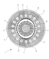
- FIG. 2 is a cross-sectional view perpendicular to the axis as seen in the section taken along the line II-II in FIG. It is a figure which shows the state which decomposed
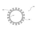
- It is a top view of the thin steel plate which comprises a tea score.
- FIG. 1 shows an axial section of the motor 1
- FIG. 2 shows an axial orthogonal section as seen in the section taken along the line II-II in FIG. 1
- FIG. Is shown. 4 and 5 show a state in which the tea core and the yoke core constituting the stator are disassembled
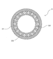
- FIG. 6 shows an axial cross section of the whole stator.
- the motor 1 mainly includes a frame 2, a stator 3, an external tooth unit 4, an output shaft 5, a fixed shaft 6, and a dummy rotor 7.
- the frame 2 (corresponding to the housing) includes a substantially cylindrical frame main body 21, a load side bracket 22 fixed so as to close an opening on one axial side (left side in FIG. 1) of the frame main body 21, An anti-load side bracket 23 fixed so as to close the opening on the other axial side of the frame body 21 (the right side in FIG. 1) is provided.
- the stator 3 includes a yoke core 31, a tee score 32, and a stator winding 33.
- a plurality of tee scores 32 are arranged in the outer circumferential direction from the annular portion 34 (corresponding to the annular connecting portion) on the inner circumferential side as shown in FIG.
- a thin steel plate 36 (silicon steel plate or the like; corresponding to the first steel plate) formed so as to provide the tooth portion 35 of the present) is laminated in the axial direction.
- An internal gear 37 is integrally formed on the inner peripheral surface of the annular portion 34 of the tee score 32.
- the yoke core 31 (corresponding to the second laminated iron core) is obtained by laminating thin steel plates 38 (silicon steel plates or the like; corresponding to the second steel plate) formed in an annular shape in the axial direction as shown in FIG. .
- a stator winding 33 is wound around each of the teeth portions 35 of the laminated tee score 32, and the entire tee score 32 is fitted to the inner peripheral surface of the yoke core 31, so that the entire stator 3 is formed as shown in FIG. It is formed in a substantially cylindrical shape.
- the entire stator 3 is fixed by being fitted to the inner peripheral surface of the frame main body 21.
- coil) of the yoke core 31 and the tee score 32 which were integrally fitted is equivalent to the stator core described in each claim.
- the external tooth unit 4 (corresponding to a cylindrical member) is made of an elastic magnetic material as a whole, and has a bottom 41 at the end on one side in the axial direction (left side in FIG. 1) and the other side is open. It is formed in a so-called cup shape.
- an external gear 42 that can be engaged with a module (tooth size) substantially the same as the internal gear 37 of the tee score 32 is integrally formed.
- the external tooth unit 4 is fixed around the shaft while penetrating the output shaft 5 at the center of the bottom 41 thereof, and the shaft with which the external gear 42 of the external tooth unit 4 and the internal gear 37 of the tee score 32 mesh. It is arranged in the direction position.
- the output shaft 5 (corresponding to a shaft) is rotatably supported through a bearing 81 while having an end on one side in the axial direction (left side in FIG. 1) penetrating and projecting through the load side bracket 22. An end portion on the other side in the direction (right side in FIG. 1) is rotatably supported by the non-load side bracket 23 via a bearing 81.
- the fixed shaft 6 is a substantially cylindrical hollow shaft formed integrally with the non-load-side bracket 23 at the end portion on the other axial side (right side in FIG. 1).
- the output shaft 5 is accommodated rotatably.
- the dummy rotor 7 (corresponding to the rotor) includes a rotor body 71, a plurality of secondary conductor bars 72, and two short-circuit rings 73.
- the rotor body 71 (corresponding to the rotor core) is entirely made of a non-conductive magnetic material, and the whole can be accommodated on the inner diameter side of the external tooth unit 4 while accommodating the fixed shaft 6 on the inner diameter side. It is formed in a substantially cylindrical shape.
- a plurality (14 in this example) of secondary conductor bars 72 (corresponding to a plurality of rod-shaped conductors) are parallel (or inclined) to the axial direction inside the rotor body 71 and are equally spaced in the circumferential direction.
- the two short-circuit rings 73 are substantially cylindrical bodies each made of a conductive material, and are fixed to both sides in the axial direction of the rotor body 71 to electrically connect the ends of the plurality of secondary conductor bars 72 on the same side. Connected to.
- the entirety of the dummy rotor 7 is rotatably supported via a bearing 81 on the fixed shaft 6 inserted through the inner diameter side of the dummy rotor 7 and is not connected to the inner diameter side of the external tooth unit 4 (rotatably). It is accommodated and arranged at an axial position overlapping the stator 3.
- the rotor body 71 is disposed opposite to the inside of the tea score 32 with the external tooth unit 4 interposed therebetween.
- Fig. 3 shows the arrangement of the connections between the main parts described above. That is, the stator 3 is axially fixed to the inner peripheral surface of the frame main body 21, and the load side bracket 22 and the anti-load side bracket 23 are axially fixed to the openings at both ends. Further, the fixed output shaft 5 and the external gear unit 4 are rotatably supported by the load side bracket 22 and the anti-load side bracket 23, and the dummy rotor 7 is rotatable on the fixed shaft 6 integral with the anti-load side bracket 23. It is supported by. That is, in the motor 1 of the present embodiment, the connecting body of the output shaft 5 and the external tooth unit 4 and the two rotating bodies of the dummy rotor 7 are arranged at axial positions overlapping with the stator 3, respectively.
- the motor 1 has an inner rotor type configuration. Yes.
- the combination of the stator 3 and the dummy rotor 7 they have the same configuration as a so-called two-pole 18-slot 14-bar squirrel-cage induction motor, but the dummy rotor 7 in this example does not output its shaft rotation. It only rotates freely.
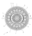
- the original pitch diameter of the external gear 42 of the external tooth unit 4 is set to be slightly smaller than the pitch diameter of the internal gear 37 of the tee score 32 and are arranged coaxially with each other. For this reason, when the motor 1 is in a non-energized state, the external gear 42 of the external tooth unit 4 and the internal gear 37 of the tee score 32 cannot mesh with each other. However, by energizing the stator winding 33 of the stator 3 and generating two magnetic poles facing each other with a phase difference of 180 ° around the central axis of the stator 3 as shown in FIG.
- the axial orthogonal cross section of the entire external tooth unit 4 made of an elastic body having magnetism is deformed by an attractive force into a substantially elliptical shape, and the external gear 42 and the internal gear 37 are locally meshed only at both ends in the long axis direction. it can.
- the magnetic flux lines between the two poles are not diffused inside the external tooth unit 4 but can be converged to the shaped magnetic flux circuit through the rotor body 71 made of a magnetic material. it can.
- the number of teeth of the external gear 42 is set to be slightly smaller than the number of teeth of the internal gear 37 (two in the example of the present embodiment).
- the combination of the internal gear 37 (corresponding to a circular spline) and the external gear 42 (corresponding to a flex spline) in mesh with each other constitutes a so-called wave gear device (harmonic drive (registered trademark)).
- the external tooth unit 4 is attached to the tee score 32. It can be rotated relatively.
- the operation will be sequentially described.
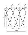
- FIG. 8 shows a waveform of a general three-phase alternating current. Three alternating currents having a phase difference of 120 ° from each other are set to Iu, Iv, and Iw in the order of electrical angles, and the timings at which the maximum value and the minimum value are set are I, II, III, IV, V, and VI in chronological order. And
- the three-phase alternating current Iu corresponds to the clockwise order of the mechanical central angle of the stator.
- Iv, and Iw are supplied in the order of electrical angles, and the alternating current of the same phase is passed in the opposite direction (that is, with a phase difference of 180 ° in terms of electrical angle) between slots facing each other by 180 ° at the mechanical center angle.
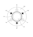
- the two magnetic pole directions shown in FIGS. 10 to 15 can be formed and sequentially rotated in the clockwise direction corresponding to the timings I, II, III, IV, V, and VI, respectively.
- the external tooth unit 104 is deformed so that the major axis direction of the substantially elliptical shape of the axis orthogonal cross section rotates in synchronization with the rotating magnetic field of the stator 103.
- the external gear unit 104 itself (and the output shaft) rotates at different speeds without being synchronized with the rotating magnetic pole. For example, when the number of teeth of the internal gear is 202 and the number of teeth of the external gear is 200, which is two less than that, the external gear unit 104 itself rotates at an angular velocity as shown in FIGS.
- the magnetic pole direction is in the horizontal direction in the figure as in FIG. 10, and the axial orthogonal cross section of the external tooth unit 104 is also substantially the long axis direction in the horizontal direction in the figure. Deforms into an ellipse.
- two external teeth at both ends in the major axis direction of the external gear meshing with the internal gear are denoted as A1 and A2.
- the major axis direction is also rotated in the clockwise direction in synchronization with the rotating magnetic pole rotating in the clockwise direction, so that the meshing position of the external gear and the internal gear is also sequentially moved in the clockwise direction.
- the magnetic pole direction is in the horizontal direction in the figure (180 ° opposite direction to FIG. 16; FIG. 10).
- the axial orthogonal cross section of the external tooth unit 104 is also deformed into a substantially elliptical shape with the major axis direction in the horizontal direction in the figure.
- FIG. 19 shows a torque characteristic in a case of a motor that uses an outer rotor system as a comparative example and does not include a secondary conductor that generates a force by an induced current (see, for example, JP-A-2002-325418).
- the operating point P1 of the rated torque and the rated speed is set using the drooping characteristic range of the starting torque region (the range where the slope of the curve is large).
- the rotating magnetic field of two poles (electrical angle 180 °) generated when the stator 3 is energized is generated on the external gear unit 4 according to the electric angle on the side of the internal gear 37 provided inside the stator 3.
- the dummy rotor 7 rotates synchronously with the movement of the magnetic field
- the external tooth unit 4 connected to the output shaft 5 has two fewer teeth than the internal gear 37 as described above, and therefore, the dummy rotor 7 performs slip rotation later than the synchronous rotation.
- the slip range can be narrowed as viewed in the entire motor 1.
- the slip range is narrow in this way, power loss in the stator 3 can be suppressed (that is, sufficient work is performed on the feeding current), and the motor 1 can be continuously operated while suppressing heat generation.
- the time can be increased, and the overall torque can be raised compared to the comparative example.
- stator 3 has a configuration of two poles and six slots
- the stator has 18 slots (see FIGS. 2 and 7 above).
- the same operation and characteristics can be obtained. That is, by supplying an alternating current to the stator winding 33 of each tooth portion 35 with an appropriate phase difference (20 ° in the case of 18 slots), a two-pole rotating magnetic field is generated similarly.
- the external tooth unit 4 can be deformed and rotated, thereby enabling a stable operation and improving torque while suppressing heat generation.
- the motor 1 according to the present embodiment is an inner rotor type motor including the external tooth unit 4 and the dummy rotor 7 inside the stator 3. Therefore, the heat generated in the stator windings 33 of the stator 3 can be easily radiated through the frame 2 and the cooling performance can be improved. Moreover, since the dummy rotor 7 can be rotated synchronously following the rotating magnetic field, the apparent slip amount with respect to the rotating magnetic field can be reduced. As a result, an increase in current can be suppressed and heat generation can be suppressed. Further, the speed-torque characteristics are greatly improved, and the efficiency can be improved.
- the dummy rotor 7 includes a plurality of rod-shaped secondary conductor bars 72 and a short-circuit ring 73.
- An induced current flows through each secondary conductor bar 72 by the rotating magnetic field of the stator winding 33, and the dummy rotor 7 receives a force in the rotating direction and rotates by the current and the rotating magnetic field.
- the dummy rotor 7 is configured to include the secondary conductor bar 72, the current suppressing effect can be enhanced and heat generation can be further suppressed. Further, the speed-torque characteristics are further improved, and the efficiency can be further increased.
- the dummy rotor 7 located on the inner diameter side of the external tooth unit 4 has the rotor main body 71 made of a magnetic material, the magnetic flux lines between the two poles released into the external tooth unit 4 are not diffused.
- the magnetic flux circuit can be shaped. This also further improves the speed-torque characteristics and further increases the efficiency.
- the tea score 32 and the internal gear 37 are integrally formed. This eliminates the need for an operation process for bonding or welding the internal gear 37 to the tee score 32 as compared with a case where it is a separate body, thereby simplifying the manufacturing process and significantly reducing the cost.
- the stator 3 has a tea score 32 and a yoke core 31.
- the stator 3 is manufactured as follows.
- the thin steel plate 36 for the tea score 32 and the thin steel plate 38 for the yoke core 31 are formed separately.
- a tooth mold is formed on the inner periphery, and when the thin steel plate 36 is punched out, a plurality of teeth portions 35 and a plurality of teeth portions 35 arranged radially are formed.
- a thin steel plate 36 (see FIG. 4 above) having an annular portion 34 with inner teeth formed on the inner periphery is formed.
- the thin steel plates 36 are laminated to form a tea score 32.
- the punching die of the thin steel plate 38 for the yoke core 31 is annular, and the cylindrical yoke core 31 is formed by laminating the annular thin steel plate 38 for the yoke core 31 formed by punching.
- the stator winding 33 is wound around the tee score 32, and then the yoke core 31 is fitted to the outside of the tee score 32, whereby the stator 3 is manufactured.
- the stator 3 configured integrally with the internal gear 37 can be manufactured. Moreover, since each teeth part 35 protrudes in the outer peripheral side in the tee score 32, the winding operation
- the internal gear 37 may be configured separately from the tee score 32 for the purpose of improving the strength against meshing with the external gear 42.
- the external tooth unit 4 is provided with a thick portion 43 in a range facing the tea score 32 on the inner periphery thereof.
- the thick portion 43 may be formed by, for example, winding a thin silicon steel plate around the inner periphery of the external tooth unit 4.
- the shafts of the stator 3A (yoke core 31A, teascore 32A), the thick portion 43A, and the dummy rotor 7A (rotor body 71A).
- the direction dimension is configured to be longer than that of the internal gear 37 and the external gear 42.
Landscapes
- Engineering & Computer Science (AREA)
- Power Engineering (AREA)
- Iron Core Of Rotating Electric Machines (AREA)
Abstract
【課題】 発熱を抑えるようにする。 【解決手段】モータ1は、フレーム2の内周に固定されたヨークコア31、ティースコア32、及び複数の固定子巻線33を備えた固定子3と、ティースコア32の内周に固定された内歯車37と、内歯車37と噛み合う外歯車42を外周に備え、固定子巻線33により生じる回転磁界により変形して外歯車42の一部を内歯車37に噛み合わせ、その噛み合い位置を順次移動させることで内歯車37に対して相対回転するように構成された、磁性を有する外歯ユニット4と、フレーム2により回転自在に支持され、外歯ユニット4に連結された出力軸5と、フレーム2に固定され、固定子3の内側に配置された固定軸6と、固定軸6周りに回転自在に支持され、ティースコア32の内側に外歯ユニット4を挟んで対向配置されたロータ本体71を備えたダミーロータ7と、を有する。
Description
開示の実施形態は、モータに関する。
特許文献1には、歯の付いた弾性体を磁性片を介して磁気力で変形させ、これを出力体と噛合させるとともに、コイルの電流を順次切り換えて噛み合い点を順次移動させていくことにより、弾性体と出力体との間に相対的な変位を得るモータが記載されている。
上記従来技術は、アウターロータ方式のモータであるので、熱源となるコイルがロータの内側に配置されており、熱を逃がしにくい。また、コイルの磁束の回転速度より大幅に減速されて出力体が回転するので、すべりが大きく、電流が増大して発熱が大きくなるという課題があった。
本発明はこのような問題点に鑑みてなされたものであり、発熱を抑えることができるモータを提供することを目的とする。
上記課題を解決するため、本発明の一の観点によれば、筐体の内周に固定された固定子鉄心及び複数の固定子巻線を備えた固定子と、前記固定子鉄心の内周に固定された内歯車と、前記内歯車と噛み合う外歯車を外周に備え、前記固定子巻線により生じる回転磁界により変形して前記外歯車の一部を前記内歯車に噛み合わせ、その噛み合い位置を順次移動させることで前記内歯車に対して相対回転するように構成された、磁性を有する筒部材と、前記筐体により回転自在に支持され、前記筒部材に連結されたシャフトと、前記筐体に固定され、前記固定子の内側に配置された固定軸と、前記固定軸周りに回転自在に支持され、前記固定子鉄心の内側に前記筒部材を挟んで対向配置された回転子鉄心を備えた回転子と、を有するモータが適用される。
また、本発明の別の観点によれば、筐体の内周に固定された固定子鉄心及び複数の固定子巻線を備えた固定子と、前記固定子鉄心の内周に固定された内歯車と、前記内歯車と噛み合う外歯車を外周に備え、前記固定子巻線により生じる回転磁界により変形して前記外歯車の一部を前記内歯車に噛み合わせ、その噛み合い位置を順次移動させることで前記内歯車に対して相対回転するように構成された、磁性を有する筒部材と、前記筐体により回転自在に支持され、前記磁性筒部材に連結されたシャフトと、前記回転磁界に追随して回転する手段と、を有するモータが適用される。
本発明によれば、発熱を抑えることができる。
以下、一実施の形態について図面を参照しつつ説明する。なお、以下では、モータの構成の説明の便宜上、上下左右等の方向を適宜使用するが、モータの各構成の位置関係を限定するものではない。
<モータの構成>
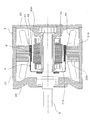
まず、図1~図6を用いて、本実施形態に係るモータ1の構成について説明する。図1はモータ1の軸方向断面を示しており、図2は図1中の矢視II-II断面で見た軸直交断面を示しており、図3は主要部位を軸方向に分解した状態を示している。また、図4、図5は固定子を構成するティースコアとヨークコアを分解した状態を示しており、図6は固定子全体の軸方向断面を示している。これら図1~図6に示すように、モータ1は、主にフレーム2と、固定子3と、外歯ユニット4と、出力軸5と、固定軸6と、ダミーロータ7とを備えている。
まず、図1~図6を用いて、本実施形態に係るモータ1の構成について説明する。図1はモータ1の軸方向断面を示しており、図2は図1中の矢視II-II断面で見た軸直交断面を示しており、図3は主要部位を軸方向に分解した状態を示している。また、図4、図5は固定子を構成するティースコアとヨークコアを分解した状態を示しており、図6は固定子全体の軸方向断面を示している。これら図1~図6に示すように、モータ1は、主にフレーム2と、固定子3と、外歯ユニット4と、出力軸5と、固定軸6と、ダミーロータ7とを備えている。
フレーム2(筐体に相当)は、略円筒形状のフレーム本体21と、このフレーム本体21の軸方向一方側(図1中の左側)の開口部を塞ぐよう固定された負荷側ブラケット22と、フレーム本体21の軸方向他方側(図1中に右側)の開口部を塞ぐよう固定された反負荷側ブラケット23とを備えている。
固定子3は、ヨークコア31と、ティースコア32と、固定子巻線33とを備えている。ティースコア32(第1の積層鉄心体に相当)は、図4に示すような内周側の円環部34(円環状の接続部に相当)から外周方向に向けて複数(この例では18本)のティース部35を設けるよう形成された薄鋼板36(ケイ素鋼板等;第1の鋼板に相当)を軸方向に積層したものである。また、ティースコア32の円環部34の内周面には内歯車37が一体に形成されている。ヨークコア31(第2の積層鉄心体に相当)は、図5に示すように円環状に形成された薄鋼板38(ケイ素鋼板等;第2の鋼板に相当)を軸方向に積層したものである。積層したティースコア32の各ティース部35に固定子巻線33を巻回し、当該ティースコア32全体をヨークコア31の内周面に嵌合することで、図6に示すように固定子3全体が略円筒形状に形成される。この固定子3は、その全体をフレーム本体21の内周面に嵌合して固定される。なお、一体に嵌合したヨークコア31とティースコア32の組み立て体(固定子巻線を除く)が、各請求項記載の固定子鉄心に相当する。
外歯ユニット4(筒部材に相当)は、全体が弾性を有する磁性体材料からなり、軸方向一方側(図1中の左側)の端部に底部41を有し他方側が開口している円筒形状、いわゆるカップ形状に形成されている。この外歯ユニット4の開口側の外周には、上記ティースコア32の内歯車37と略同じモジュール(歯の大きさ)で噛合い可能な外歯車42が一体に形成されている。また、外歯ユニット4はその底部41の中心に出力軸5を貫通させつつ軸周りに固定されており、当該外歯ユニット4の外歯車42と上記ティースコア32の内歯車37が噛合する軸方向位置に配置されている。
出力軸5(シャフトに相当)は、その軸方向一方側(図1中の左側)の端部を負荷側ブラケット22に貫通、突出させつつベアリング81を介して回転自在に支持されるとともに、軸方向他方側(図1中の右側)の端部がベアリング81を介して反負荷側ブラケット23に回転自在に支持されている。
固定軸6は、本実施形態の例ではその軸方向他方側(図1中の右側)の端部で反負荷側ブラケット23と一体に形成された略円筒形状の中空軸であり、その内径には上記出力軸5が回転自在に収容される。
ダミーロータ7(回転子に相当)は、ロータ本体71と、複数の二次導体バー72と、2つの短絡環73とを備えている。ロータ本体71(回転子鉄心に相当)は、全体が非導電性の磁性材料からなり、その全体は上記外歯ユニット4の内径側に収容されつつ上記固定軸6をその内径側に収容可能な略円筒形状に形成されている。複数(この例では14本)の二次導体バー72(複数の棒状の導体に相当)は、それぞれロータ本体71の内部で軸方向と平行(もしくは傾斜)かつ円周方向に均等な間隔で当該ロータ本体71を軸方向に貫通するよう設けられている(図2参照)。2つの短絡環73は、それぞれ導電性材料からなる略円筒形状体であり、ロータ本体71の軸方向両側にそれぞれ固定されて上記複数の二次導体バー72の同じ側の端部どうしを電気的に接続している。ダミーロータ7の全体は、その内径側に挿通する上記固定軸6にベアリング81を介して回転自在に支持されているとともに、上記外歯ユニット4の内径側で連結されることなく(回転自在に)収容されて上記固定子3と重複する軸方向位置に配置されている。特にロータ本体71に関しては、ティースコア32の内側に外歯ユニット4を挟んで対向配置されている。
以上説明した主要部位間の連結構成を整理すると、図3のようになる。すなわち、フレーム本体21には、その内周面に固定子3が軸固定され、両端の開口部に負荷側ブラケット22と反負荷側ブラケット23が軸固定される。また、軸固定した出力軸5と外歯ユニット4は負荷側ブラケット22と反負荷側ブラケット23に回転自在に支持されており、ダミーロータ7は反負荷側ブラケット23と一体の固定軸6に回転自在に支持されている。つまり、本実施形態のモータ1内には、出力軸5と外歯ユニット4の連結体と、ダミーロータ7の2つの回転体が、それぞれ固定子3と重複する軸方向位置に配置されつつそれぞれ独立して回転自在に備えられている。そして、軸出力を行う方の回転体(出力軸5と外歯ユニット4の連結体)が固定子3の内径側に配置されていることから、当該モータ1はインナーロータ型の構成となっている。また、固定子3とダミーロータ7の組み合わせに着目すると、これらはいわゆる2極18スロット14バーのかご型誘導モータと同等の構成となるが、この例のダミーロータ7はその軸回転を出力せずに自由に回転するだけである。
<外歯車と内歯車の噛み合い構成>
外歯ユニット4の外歯車42の本来のピッチ径はティースコア32の内歯車37のピッチ径よりも少し小さく設定されており、かつ互いに同軸的に配置されている。このためモータ1が無通電状態となっている際には、外歯ユニット4の外歯車42とティースコア32の内歯車37は噛み合うことができない。しかし、固定子3の固定子巻線33に通電して、図7に示すように固定子3の中心軸周りに180°の位相差で対向する2極の磁極を発生させることで、それぞれの吸引力により磁性を有する弾性体からなる外歯ユニット4全体の軸直交断面を略楕円形に変形させ、その長軸方向の両端部だけ局所的に外歯車42と内歯車37を噛み合わせることができる。なおこの際には、図示するように外歯ユニット4の内部において2極間の磁束線を拡散させることなく、磁性体からなるロータ本体71を通過して整形された磁束回路に収束させることができる。
外歯ユニット4の外歯車42の本来のピッチ径はティースコア32の内歯車37のピッチ径よりも少し小さく設定されており、かつ互いに同軸的に配置されている。このためモータ1が無通電状態となっている際には、外歯ユニット4の外歯車42とティースコア32の内歯車37は噛み合うことができない。しかし、固定子3の固定子巻線33に通電して、図7に示すように固定子3の中心軸周りに180°の位相差で対向する2極の磁極を発生させることで、それぞれの吸引力により磁性を有する弾性体からなる外歯ユニット4全体の軸直交断面を略楕円形に変形させ、その長軸方向の両端部だけ局所的に外歯車42と内歯車37を噛み合わせることができる。なおこの際には、図示するように外歯ユニット4の内部において2極間の磁束線を拡散させることなく、磁性体からなるロータ本体71を通過して整形された磁束回路に収束させることができる。
ここで、外歯車42の歯数は内歯車37の歯数より少しだけ少なく(本実施形態の例では2つ少なく)設定されている。このように噛合した状態の内歯車37(サーキュラスプラインに相当)と外歯車42(フレックススプラインに相当)の組み合わせは、いわゆる波動歯車装置(ハーモニックドライブ(登録商標))を構成する。そして、ティースコア32の各固定子巻線33に3相交流電力を給電して当該ティースコア32の中心軸周りに回転する磁界を発生させることで、外歯ユニット4をティースコア32に対して相対的に回転させることができる。以下、その動作について順次説明する。
<回転磁界と外歯車の変形について>
ここでは説明を簡易にするために、固定子が2極6スロット(2P6S)の構成であるモータのモデルに基づいて説明する。図8は、一般的な3相交流電流の波形を示している。互いに120°の位相差の関係にある3つの交流電流を電気角順にIu,Iv,Iwとし、それぞれの最大値、最小値となるタイミングを時系列順にI,II,III,IV,V,VIとする。
ここでは説明を簡易にするために、固定子が2極6スロット(2P6S)の構成であるモータのモデルに基づいて説明する。図8は、一般的な3相交流電流の波形を示している。互いに120°の位相差の関係にある3つの交流電流を電気角順にIu,Iv,Iwとし、それぞれの最大値、最小値となるタイミングを時系列順にI,II,III,IV,V,VIとする。
この3相交流電流を、図9に示す6スロット(ティース部が6つ)の構成の固定子103に給電する場合、固定子の機械的な中心角の時計方向順に対応して3相交流Iu,Iv,Iwを電気角順に給電し、かつ機械的な中心角で180°対向するスロットどうしは同相の交流電流を逆方向に(つまり電気角で180°の位相差で)通電させる。これにより、上記タイミングI,II,III,IV,V,VIにそれぞれ対応して、図10~図15のそれぞれに示す2極の磁極方向を形成して順次時計方向に回転させることができる。
<外歯ユニット及びダミーロータの回転について>
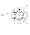
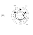
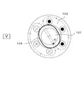
上記のように、外歯ユニット104は、その軸直交断面の略楕円形状の長軸方向が固定子103の回転磁界に同期して回転するよう変形する。しかし、外歯車と内歯車の噛み合いがあるため、外歯ユニット104自体(及び出力軸)は回転磁極に同期せずに異なる速度で回転する。例えば、内歯車の歯数を202とし、外歯車の歯数をそれより2つ少ない200とした場合には、図16~図18に示すような角速度で外歯ユニット104自体が回転する。
上記のように、外歯ユニット104は、その軸直交断面の略楕円形状の長軸方向が固定子103の回転磁界に同期して回転するよう変形する。しかし、外歯車と内歯車の噛み合いがあるため、外歯ユニット104自体(及び出力軸)は回転磁極に同期せずに異なる速度で回転する。例えば、内歯車の歯数を202とし、外歯車の歯数をそれより2つ少ない200とした場合には、図16~図18に示すような角速度で外歯ユニット104自体が回転する。
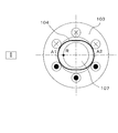
まず、タイミングIに対応する図16では、上記図10と同様に磁極方向が図中の横方向に向き、外歯ユニット104の軸直交断面も長軸方向を図中の横方向に向けた略楕円形に変形する。このときに内歯車と噛み合う外歯車の長軸方向両端部の2つの外歯をA1,A2とする。その後に時計方向に回転する回転磁極に同期して長軸方向も時計方向に回転することで、外歯車と内歯車の噛み合い位置も順次時計方向に移動する。
そしてタイミングII,IIIを経て1/2回転した際のタイミングIVに対応する図17では、上記図13と同様に磁極方向が図中の横方向に向き(図16と180°逆方向;図10、図13参照)、外歯ユニット104の軸直交断面も長軸方向を図中の横方向に向けた略楕円形に変形する。しかし、外歯車の歯数が内歯車の歯数より2つ少ないため、この時点で長軸方向両端における内歯車との噛み合い位置は上記の外歯A1,A2から見てそれぞれ歯の1つ分だけずれている。すなわち、外歯車における1つ分の歯の角度=1.8°だけ、外歯ユニット104自体が固定子103に対して反時計方向に相対的に回転し、出力軸を介して出力したことになる。
さらにタイミングV,VIを経て1回転した際のタイミングIに対応する図18では、この時点で長軸方向両端における外歯車と内歯車との噛み合い位置は上記の外歯A1,A2から見てそれぞれ歯の2つ分だけずれている。すなわち、外歯車における2つ分の歯の角度=3.6°だけ、外歯ユニット104自体が固定子103に対して反時計方向に相対的に回転したことになる。この場合、外歯ユニット104自体を反時計方向に1回転(360°回転)させるためには、回転磁界を時計方向に100回転させる必要がある。つまり、内歯車と外歯車の歯数比を202:200に設定した場合には、結果的に回転磁界に対して1/100の減速比を得ることができる。
なお、上述したようにティースコア32と、複数の二次導体バー72及び2つの短絡環73を備えているダミーロータ7の組み合わせは誘導モータと同等の構成にあり、ダミーロータ7には負荷トルクが付加されずフリーで回転するため回転磁界に対して同じ回転方向の同じ回転速度(負荷トルク=0の場合の同期速度)で同期回転する(図10~図18中におけるダミーロータ107外周の点R参照)。
<モータのトルク特性について>
図19は、比較例としてアウターロータ方式で、かつ誘起された電流で力を発生する二次導体をロータに備えていないモータの場合(例えば特開2002-325418号公報参照)のトルク特性を示しており、図20はダミーロータ7を備えた本実施形態のインナーロータ型モータの場合のトルク特性を示している。いずれも固定子3を上述した2極の誘導電動機に3相交流電流を給電した場合を示している(この場合はトルク=0で同期速度=3600rpm固定)。
図19は、比較例としてアウターロータ方式で、かつ誘起された電流で力を発生する二次導体をロータに備えていないモータの場合(例えば特開2002-325418号公報参照)のトルク特性を示しており、図20はダミーロータ7を備えた本実施形態のインナーロータ型モータの場合のトルク特性を示している。いずれも固定子3を上述した2極の誘導電動機に3相交流電流を給電した場合を示している(この場合はトルク=0で同期速度=3600rpm固定)。
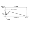
図19に示した比較例では、アウターロータ型の構造であるために外部への磁気漏れが大きく、かつ二次導体も有していないため高い電流が流れても発生トルクも小さく、比較的低い回転数で停動トルク(極大値トルク)となる。これにより、停動トルク時の回転速度と無負荷トルク時の同期速度の間ではトルク曲線の傾きが小さくなり、すなわちこの範囲ではトルク変動に対して回転速度も大きく変動してしまう。このために、比較例では起動トルク領域の垂下特性範囲(曲線の傾きの大きい範囲)を利用して定格トルクと定格速度の運転点P1を設定する。しかしこの場合には、運転点P1が特に磁気漏れのために漂遊負荷損が大きい漂遊負荷損領域の近傍に設定されるため、動作が不安定になりやすいという問題がある。また、この比較例では、ダミーロータ7を備えずに1/100に減速した出力軸5だけを回転駆動しているため、この実出力速度と同期速度との差であるスリップ範囲が大きくなっている。これにより、固定子3における電力の損失が大きくなり(つまり給電電流が仕事をしていない)、その分だけモータの発熱が大きく、持続的に運転できる時間も短くせざるを得ない。
これに対して図20に示した本実施形態では、インナーロータ型の構造であるために、固定子3から外部への磁気漏れは少なく、また二次導体を有するダミーロータ7を設けているので低い電流の流れで発生トルクも大きくなることから停動トルク時の回転速度を上げることができ、すなわち無負荷トルク時の同期速度との間のトルク曲線の傾きを大きくして垂下特性を持たせることができる。これにより、この停動トルク時の回転速度と無負荷トルク時の同期速度との間の垂下特性範囲に定格速度と定格トルクの運転点P2を設定することができ、トルク変動に対しても回転速度の変動幅を抑えた安定した動作が可能となる。また、本実施形態では、固定子3通電した際に生じる2極(電気角180°)の回転磁界が、固定子3の内側に設けた内歯車37側に電気角に応じて外歯ユニット4を楕円状に吸引し、その歯同士が噛み合い、順次回転磁界の動きに沿って回転する。ダミーロータ7は磁界の動きと同期回転するが、出力軸5とつながっている外歯ユニット4は、内歯車37より歯数が前述したように2つ少ないので、同期回転より遅れスリップ回転をするために、モータ1全体で見てスリップ範囲を狭めることができる。このようにスリップ範囲が狭いことで固定子3における電力の損失を抑える(つまり給電電流に十分な仕事をさせている)ことができ、その分だけモータ1の発熱を抑えて持続的に運転できる時間も長くできるとともに、比較例と比較しても全体のトルクを底上げできる。
なお、上記図9~図20では、固定子3が2極6スロットの構成である場合を例に説明したが、本実施形態のように18スロット(上記図2,図7参照)で固定子3を構成する場合でも同様の動作、特性を得ることができる。つまり、各ティース部35の固定子巻線33にそれぞれ適宜の位相差(18スロットの場合は20°)を持たせて交流電流を給電することで、同様に2極の回転磁界を発生させて外歯ユニット4を変形、回転させることができ、これにより安定動作が可能で発熱を抑えつつトルクの向上を図ることができる。
<本実施形態の効果>
以上説明したように、本実施形態のモータ1は、固定子3の内側に外歯ユニット4やダミーロータ7を備えたインナーロータ方式のモータである。したがって、固定子3の固定子巻線33で発生した熱がフレーム2を介して放熱し易く、冷却性能を向上できる。また、ダミーロータ7を回転磁界に追随して同期回転させることができるので、回転磁界に対する見かけ上のすべり量を低減することができる。その結果、電流の増大を抑制し、発熱を抑えることができる。また、速度-トルク特性が大幅に改善され、効率を向上できる。
以上説明したように、本実施形態のモータ1は、固定子3の内側に外歯ユニット4やダミーロータ7を備えたインナーロータ方式のモータである。したがって、固定子3の固定子巻線33で発生した熱がフレーム2を介して放熱し易く、冷却性能を向上できる。また、ダミーロータ7を回転磁界に追随して同期回転させることができるので、回転磁界に対する見かけ上のすべり量を低減することができる。その結果、電流の増大を抑制し、発熱を抑えることができる。また、速度-トルク特性が大幅に改善され、効率を向上できる。
また、本実施形態では特に、ダミーロータ7が、複数の棒状の二次導体バー72と、短絡環73とを有している。固定子巻線33の回転磁界により各二次導体バー72に誘導電流が流れ、その電流と回転磁界によりダミーロータ7が回転方向に力を受け回転する。このように、ダミーロータ7が二次導体バー72を有する構成とするので、電流の抑制効果を高め、発熱をより抑えることができる。また、速度-トルク特性がさらに改善され、効率をより高めることができる。さらに、外歯ユニット4の内径側に位置するダミーロータ7が磁性材料からなるロータ本体71を有していることにより、外歯ユニット4の内部に放出される2極間の磁束線を拡散させずに磁束回路を整形できる。これによっても、速度-トルク特性がさらに改善され、効率をより高めることができる。
また、本実施形態では特に、ティースコア32と内歯車37とが一体に構成されている。これにより、別体とする場合に比べて、内歯車37をティースコア32に接着あるいは溶接する作業工程が不要となるので、製造工程を簡易化でき、コストを大幅に低減できる。
また、本実施形態では特に、固定子3がティースコア32とヨークコア31とを有する。この固定子3は、次のようにして製造される。
すなわち、帯状の鋼板から固定子3用の鋼板をプレス抜きにて順次形成する際に、ティースコア32用の薄鋼板36と、ヨークコア31用の薄鋼板38とが、別々に形成される。ティースコア32用の薄鋼板36のプレス抜き型には内周に歯型が形成されており、薄鋼板36を打ち抜いた際に、放射状に配置された複数のティース部35及び複数のティース部35を接続し内周に内歯が形成された円環部34を備えた形状の薄鋼板36(上記図4参照)が形成される。この薄鋼板36が積層されて、ティースコア32が形成される。ヨークコア31用の薄鋼板38のプレス抜き型は円環状であり、プレス抜きにて形成された円環状のヨークコア31用の薄鋼板38が積層されて、円筒状のヨークコア31が形成される。ティースコア32に固定子巻線33が巻き回され、その後ヨークコア31がティースコア32の外側にはめ合わされることで、固定子3が製造される。
以上のようにして、内歯車37と一体に構成された固定子3を製造することができる。また、ティースコア32では各ティース部35が外周側に突出しているので、巻線33の巻回作業が容易となる。なお、特に図示しないが、外歯車42との噛み合いに対する強度の向上などの目的で、内歯車37をティースコア32と別体で構成してもよい。
<変形例>
なお、開示の実施形態は、上記に限られるものではなく、その趣旨及び技術的思想を逸脱しない範囲内で種々の変形が可能である。以下、そのような変形例を説明する。
なお、開示の実施形態は、上記に限られるものではなく、その趣旨及び技術的思想を逸脱しない範囲内で種々の変形が可能である。以下、そのような変形例を説明する。
(1)外歯ユニットの内周に厚肉部を設ける場合
例えば、内歯車37と外歯車42による減速比が小さい場合、内歯及び外歯のモジュールが大きくなるのでそれぞれの歯山が高くなり、歯同士が干渉しやすくなる。これに対し、内歯車37のピッチ径に対して外歯車42の本来のピッチ径を小さくすることで歯同士の干渉を回避できるが、この場合には磁極方向両端における噛み合いを確保するために外歯ユニット4をより大きな変形量(偏平率)で変形させる必要がある。
例えば、内歯車37と外歯車42による減速比が小さい場合、内歯及び外歯のモジュールが大きくなるのでそれぞれの歯山が高くなり、歯同士が干渉しやすくなる。これに対し、内歯車37のピッチ径に対して外歯車42の本来のピッチ径を小さくすることで歯同士の干渉を回避できるが、この場合には磁極方向両端における噛み合いを確保するために外歯ユニット4をより大きな変形量(偏平率)で変形させる必要がある。
このため本変形例では、上記図1に対応する図21に示すように、外歯ユニット4が、その内周においてティースコア32と対向する範囲に厚肉部43を設けている。この厚肉部43は、例えば薄肉のケイ素鋼板を外歯ユニット4の内周に巻回して形成すればよい。これにより、回転磁界による外歯ユニット4の吸引力を増大させて変形量を大きくすることができるので、減速比が小さい場合でも上述した歯の干渉を防止することができる。
(2)固定子、厚肉部、及びダミーロータを、内歯車及び外歯車よりも長く形成する場合
例えば、インバータによりモータ1の電流制御を行う際に、電流をモータ1の定格電流より下げた場合、回転磁界による吸引力の減少により外歯ユニット4の変形量が小さくなり、内歯車37と外歯車42との噛み合いが外れる可能性がある。
例えば、インバータによりモータ1の電流制御を行う際に、電流をモータ1の定格電流より下げた場合、回転磁界による吸引力の減少により外歯ユニット4の変形量が小さくなり、内歯車37と外歯車42との噛み合いが外れる可能性がある。
このため本変形例では、上記図1、図21に対応する図22に示すように、固定子3A(ヨークコア31A、ティースコア32A)、厚肉部43A、及びダミーロータ7A(ロータ本体71A)の軸方向寸法を、内歯車37及び外歯車42よりも長くなるように構成している。これにより、外歯ユニット4を吸引する面積を増大することができるので、電流が低下して単位面積当たりの吸引力が減少した場合でも、内歯車37と外歯車42との噛み合いを維持することが可能である。
なお、以上の説明における「平行」とは、厳密な意味での平行ではない。すなわち、「平行」とは、設計上、製造上の公差、誤差が許容され、「実質的に平行」という意味である。
なお、以上の説明における「等しい」、「均等」とは、厳密な意味ではない。すなわち、「等しい」、「均等」とは、設計上、製造上の公差、誤差が許容され、「実質的に等しい」、「実質的に均等」という意味である。
また、以上既に述べた以外にも、上記実施形態や各変形例による手法を適宜組み合わせて利用しても良い。
その他、一々例示はしないが、上記実施形態や各変形例は、その趣旨を逸脱しない範囲内において、種々の変更が加えられて実施されるものである。
1 モータ
2 フレーム(筐体)
3,3A 固定子
4 外歯ユニット(筒部材)
5 出力軸(シャフト)
6 固定軸
7,7A ダミーロータ(回転子)
31,31A ヨークコア(第2の積層鉄心体)
32,32A ティースコア(第1の積層鉄心体)
33 固定子巻線
34 円環部(円環状の接続部)
35 ティース部
36 薄鋼板(第1の鋼板)
37 内歯車
38 薄鋼板(第2の鋼板)
42 外歯車
43,43A 厚肉部
71,71A ロータ本体(回転子鉄心)
72 二次導体バー(棒状の導体)
73 短絡環
2 フレーム(筐体)
3,3A 固定子
4 外歯ユニット(筒部材)
5 出力軸(シャフト)
6 固定軸
7,7A ダミーロータ(回転子)
31,31A ヨークコア(第2の積層鉄心体)
32,32A ティースコア(第1の積層鉄心体)
33 固定子巻線
34 円環部(円環状の接続部)
35 ティース部
36 薄鋼板(第1の鋼板)
37 内歯車
38 薄鋼板(第2の鋼板)
42 外歯車
43,43A 厚肉部
71,71A ロータ本体(回転子鉄心)
72 二次導体バー(棒状の導体)
73 短絡環
Claims (7)
- 筐体の内周に固定された固定子鉄心及び複数の固定子巻線を備えた固定子と、
前記固定子鉄心の内周に固定された内歯車と、
前記内歯車と噛み合う外歯車を外周に備え、前記固定子巻線により生じる回転磁界により変形して前記外歯車の一部を前記内歯車に噛み合わせ、その噛み合い位置を順次移動させることで前記内歯車に対して相対回転するように構成された、磁性を有する筒部材と、
前記筐体により回転自在に支持され、前記筒部材に連結されたシャフトと、
前記筐体に固定され、前記固定子の内側に配置された固定軸と、
前記固定軸周りに回転自在に支持され、前記固定子鉄心の内側に前記筒部材を挟んで対向配置された回転子鉄心を備えた回転子と、
を有することを特徴とするモータ。 - 前記回転子は、
前記回転子鉄心に設けられた複数の棒状の導体と、
前記回転子鉄心の軸方向両側に配置され、前記複数の導体を接続する短絡環と、を有する
ことを特徴とする請求項1に記載のモータ。 - 前記固定子鉄心と前記内歯車とは、
一体に構成される
ことを特徴とする請求項1又は2に記載のモータ。 - 前記固定子鉄心は、
放射状に配置された複数のティース部及び前記複数のティース部を接続し内周に内歯が形成された円環状の接続部を備えた第1の鋼板が積層された第1の積層鉄心体と、
前記第1の積層鉄心体の外側にはめ合わされ、円環状の第2の鋼板が積層された第2の積層鉄心体と、を有する
ことを特徴とする請求項3に記載のモータ。 - 前記筒部材は、
内周の前記固定子鉄心と対向する範囲に厚肉部を有する
ことを特徴とする請求項1乃至4のいずれか1項に記載のモータ。 - 前記固定子鉄心、前記厚肉部、及び前記回転子は、
前記内歯車及び前記外歯車よりも軸方向寸法が長い
ことを特徴とする請求項5に記載のモータ。 - 筐体の内周に固定された固定子鉄心及び複数の固定子巻線を備えた固定子と、
前記固定子鉄心の内周に固定された内歯車と、
前記内歯車と噛み合う外歯車を外周に備え、前記固定子巻線により生じる回転磁界により変形して前記外歯車の一部を前記内歯車に噛み合わせ、その噛み合い位置を順次移動させることで前記内歯車に対して相対回転するように構成された、磁性を有する筒部材と、
前記筐体により回転自在に支持され、前記磁性筒部材に連結されたシャフトと、
前記回転磁界に追随して回転する手段と、
を有することを特徴とするモータ。
Priority Applications (1)
| Application Number | Priority Date | Filing Date | Title |
|---|---|---|---|
| PCT/JP2014/061193 WO2015162673A1 (ja) | 2014-04-21 | 2014-04-21 | モータ |
Applications Claiming Priority (1)
| Application Number | Priority Date | Filing Date | Title |
|---|---|---|---|
| PCT/JP2014/061193 WO2015162673A1 (ja) | 2014-04-21 | 2014-04-21 | モータ |
Publications (1)
| Publication Number | Publication Date |
|---|---|
| WO2015162673A1 true WO2015162673A1 (ja) | 2015-10-29 |
Family
ID=54331868
Family Applications (1)
| Application Number | Title | Priority Date | Filing Date |
|---|---|---|---|
| PCT/JP2014/061193 Ceased WO2015162673A1 (ja) | 2014-04-21 | 2014-04-21 | モータ |
Country Status (1)
| Country | Link |
|---|---|
| WO (1) | WO2015162673A1 (ja) |
Citations (5)
| Publication number | Priority date | Publication date | Assignee | Title |
|---|---|---|---|---|
| JPS4815049B1 (ja) * | 1964-11-04 | 1973-05-11 | ||
| JP2683364B2 (ja) * | 1988-07-01 | 1997-11-26 | 株式会社ハーモニック・ドライブ・システムズ | ステップモータ |
| JP2003284317A (ja) * | 2002-03-20 | 2003-10-03 | Sofutoronikusu Kk | 永久磁石を用いた調和歯車装置 |
| JP2007181348A (ja) * | 2005-12-28 | 2007-07-12 | Ginga Denki Kogyo Kk | ステータの製造方法 |
| US20120204674A1 (en) * | 2007-12-05 | 2012-08-16 | Ivan Lundberg | Harmonic motor, drive assembly, industrial robot, robot boom and robot joint |
-
2014
- 2014-04-21 WO PCT/JP2014/061193 patent/WO2015162673A1/ja not_active Ceased
Patent Citations (5)
| Publication number | Priority date | Publication date | Assignee | Title |
|---|---|---|---|---|
| JPS4815049B1 (ja) * | 1964-11-04 | 1973-05-11 | ||
| JP2683364B2 (ja) * | 1988-07-01 | 1997-11-26 | 株式会社ハーモニック・ドライブ・システムズ | ステップモータ |
| JP2003284317A (ja) * | 2002-03-20 | 2003-10-03 | Sofutoronikusu Kk | 永久磁石を用いた調和歯車装置 |
| JP2007181348A (ja) * | 2005-12-28 | 2007-07-12 | Ginga Denki Kogyo Kk | ステータの製造方法 |
| US20120204674A1 (en) * | 2007-12-05 | 2012-08-16 | Ivan Lundberg | Harmonic motor, drive assembly, industrial robot, robot boom and robot joint |
Similar Documents
| Publication | Publication Date | Title |
|---|---|---|
| JP7576113B2 (ja) | 磁束機械 | |
| JP4926107B2 (ja) | 回転電機 | |
| US8552609B2 (en) | Synchronous motor and system for driving synchronous motor | |
| JP5341908B2 (ja) | 同期電動機 | |
| EP3062426A1 (en) | Single-phase brushless motor | |
| JP2001037133A (ja) | ステータ及び電動機 | |
| KR101265825B1 (ko) | 이중 고정자 rfpm 발전기 | |
| CN105871156B (zh) | 感应同步电动机 | |
| JP2014533086A (ja) | 厚さが異なる永久磁石を有する回転子及びそれを含むモータ | |
| EP3007336A1 (en) | Synchronous electric machine with two rotors | |
| JP2014045630A (ja) | 回転電機 | |
| KR100565219B1 (ko) | 회전 마그네트 타입 유도 전동기 | |
| EP1964242B1 (en) | Rotor assembly for use in line start permanent magnet synchronous motor | |
| CN108964388A (zh) | 一种开关磁阻电机 | |
| WO2007061135A2 (en) | Electrical machine having a flattened stator with inclined teeth | |
| JP2008061485A (ja) | 交流電源で自起動可能な永久磁石型モータ | |
| CN104795952B (zh) | 开关磁阻电机 | |
| JP5778391B2 (ja) | 同期回転機 | |
| JP2018102090A (ja) | ステータおよびモータ | |
| KR20120129162A (ko) | 길이가 다른 도체바를 갖는 회전자 및 그를 포함하는 lspm 모터 | |
| US20240235360A1 (en) | Magnetic geared rotating machine, power generation system, and drive system | |
| WO2015162673A1 (ja) | モータ | |
| JP5460807B1 (ja) | 同期電動機 | |
| CN214013962U (zh) | 定子芯组件、定子组件、及电机装置 | |
| TWI587609B (zh) | Brushless DC motor |
Legal Events
| Date | Code | Title | Description |
|---|---|---|---|
| 121 | Ep: the epo has been informed by wipo that ep was designated in this application |
Ref document number: 14889912 Country of ref document: EP Kind code of ref document: A1 |
|
| NENP | Non-entry into the national phase |
Ref country code: DE |
|
| 122 | Ep: pct application non-entry in european phase |
Ref document number: 14889912 Country of ref document: EP Kind code of ref document: A1 |
|
| NENP | Non-entry into the national phase |
Ref country code: JP |