WO2015159985A1 - 車両駆動用モータの積層鉄心の製造方法 - Google Patents
車両駆動用モータの積層鉄心の製造方法 Download PDFInfo
- Publication number
- WO2015159985A1 WO2015159985A1 PCT/JP2015/061900 JP2015061900W WO2015159985A1 WO 2015159985 A1 WO2015159985 A1 WO 2015159985A1 JP 2015061900 W JP2015061900 W JP 2015061900W WO 2015159985 A1 WO2015159985 A1 WO 2015159985A1
- Authority
- WO
- WIPO (PCT)
- Prior art keywords
- laminated
- arc
- iron core
- core pieces
- shaped
- Prior art date
- Legal status (The legal status is an assumption and is not a legal conclusion. Google has not performed a legal analysis and makes no representation as to the accuracy of the status listed.)
- Ceased
Links
Images



Classifications
-
- H—ELECTRICITY
- H02—GENERATION; CONVERSION OR DISTRIBUTION OF ELECTRIC POWER
- H02K—DYNAMO-ELECTRIC MACHINES
- H02K15/00—Processes or apparatus specially adapted for manufacturing, assembling, maintaining or repairing of dynamo-electric machines
- H02K15/02—Processes or apparatus specially adapted for manufacturing, assembling, maintaining or repairing of dynamo-electric machines of stator or rotor bodies
Definitions
- the present invention relates to a method for manufacturing a laminated core of a vehicle drive motor.
- Japanese Patent Application Laid-Open No. 2013-5628 describes a laminated iron core formed by sequentially caulking and laminating annular iron core pieces composed of a plurality of segment iron core pieces arranged in a ring shape.
- the present invention has been made in view of the above facts, and an object of the present invention is to provide a method for manufacturing a laminated core of a vehicle drive motor that can reduce the manufacturing cost.
- a method for manufacturing a laminated iron core for a vehicle driving motor includes a pressing step of manufacturing a single plate with a carrier in which a plurality of arc-shaped iron core pieces are connected by a connecting portion by pressing a strip-shaped magnetic steel plate, The arc-shaped core pieces are sequentially cut off from the single plate with the carrier to be conveyed, and the plurality of the ring-shaped core pieces are arranged in a circumferential direction while arranging the cut-off arc-shaped core pieces in a ring shape.
- the laminated iron core of the vehicle drive motor can be manufactured by the above pressing process, laminating process, and welding process, dedicated equipment for performing caulking and laminating simultaneously becomes unnecessary. As a result, the manufacturing cost can be reduced. Moreover, since the pressing process and the laminating process are separate processes, it is not necessary to match the production speed of one process with the production speed of the other process. Thereby, the productivity of a process with a high production speed can be improved.
- the manufacturing cost can be reduced.
- FIG. 2 is a schematic cross-sectional view showing a cut surface along the line F3-F3 of FIG.
- FIG. 2 is a schematic cross-sectional view showing a cut surface along the line F3-F3 of FIG.
- FIG. 2 is a schematic cross-sectional view showing a cut surface along the line F3-F3 of FIG.
- FIG. 2 is a front view which shows the lamination
- the laminated core 10 manufactured by the manufacturing method of the laminated core of the vehicle drive motor which concerns on this embodiment is demonstrated.
- the laminated core 10 is a laminated rotor core used on the rotor side of a vehicle drive motor (electric motor), and is a constituent element of a rotor with magnets.
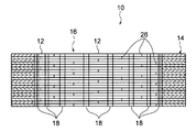
- the laminated core 10 includes a laminated core body 16 formed by laminating a plurality of annular core pieces 14 in which arc-shaped core pieces 12 (divided core pieces) divided into four pieces are arranged in a ring shape. Is formed by being integrated by a plurality of welds 18.
- Each arc-shaped iron core piece 12 has an arc angle ⁇ set to 90 degrees in this embodiment.
- a plurality of (here, four) arc-shaped magnet mounting portions 20 (magnetic pole pieces) arranged in the circumferential direction are formed on the outer peripheral portion of each arc-shaped core piece 12. These magnet mounting portions 20 have an arc angle ⁇ of 22.5 degrees, and each magnet mounting portion 20 has a magnet mounting hole 22 for mounting a magnet.
- each annular core piece 14 a plurality (four in this case) of circular guide holes arranged in the circumferential direction of each annular core piece 14 are formed in the width direction intermediate part (intermediate part between the outer circumference and the inner circumference) of each arc-shaped core piece 12. 24 is formed. These guide holes 24 are used to insert guide pins 68 provided in an alignment jig 62 (see FIGS. 7 and 8) used when the plurality of annular core pieces 14 are laminated and when the laminated core body 16 is welded. Pilot hole.
- the guide hole 24 and the magnet mounting portion 20 are provided so as to be arranged every 22.5 degrees in a state where the circular core pieces 14 are arranged by arranging the circular core pieces 12 in a ring shape.
- the hole 24 is provided in the same phase as the magnet mounting portion 20 in the circumferential direction of the annular core piece 14.
- the annular core pieces 14 that are overlapped with each other are laminated in a so-called brick pile, with the joints 26 between the arc-shaped core pieces 12 in the circumferential direction being phase-shifted in the circumferential direction.
- the phase shift angle is set to 22.5 degrees, which is the same as the arc angle ⁇ of the magnet mounting portion 20.
- the magnet mounting portion 20 and the guide hole 24 are arranged every 22.5 degrees, and therefore each of the magnet mounting portion 20 and the guide hole 24 is provided.
- the position of coincides with the stacking direction. Therefore, the magnet mounting part 20 and the guide hole 24 penetrate from the one axial end side of the laminated core body 16 to the other axial end side.
- a plurality of welded portions 18 for integrating the plurality of annular core pieces 14 laminated as described above are provided in the inner circumferential portion of the laminated core body 16 in the circumferential direction.
- the plurality of welds 18 are provided in the same number as the number of magnetic poles of the laminated core body 16 (here, 16 poles), and the arc-shaped core pieces 12 of each layer that are out of phase in the circumferential direction are arranged in the lamination direction. Welding (joining) along.
- the plurality of welded portions 18 are located on the opposite side of the magnet mounting portion 20 through the guide holes 24, and are provided on the inner peripheral portion of the laminated core body 16 every 22.5 degrees.
- the manufacturing method of the laminated core 10 is comprised by the press process which is the 1st process, the lamination process which is the 2nd process, the welding process which is the 3rd process, and the inspection process which is the 4th process.
- a single plate 30 with a carrier in which a plurality of arc-shaped core pieces 12 are connected by a pair of connecting portions 32 by pressing a strip-shaped magnetic steel plate with a die device (see FIGS. 4 to 6). Manufacturing. Then, the manufactured single plate 30 with a carrier is wound around a reel 34 (see FIG. 4), and the process proceeds to the next stacking step.
- the arc-shaped core pieces 12 are sequentially separated from the single plate 30 with the carrier to be conveyed, and the plurality of annular core pieces 14 are formed while arranging the separated arc-shaped core pieces 12 in a ring shape to form the annular core pieces 14.
- the laminated core body 16 is manufactured by laminating with the phases shifted in the circumferential direction. Specifically, first, the reel 34 is attached to the reel stand 36 shown in FIG. 4, and the single plate 30 with the carrier wound around the reel 34 is unwound so that the laminated assembly apparatus 38 shown in FIG. 4 and FIG. It is wound around the guide roller 40 and inserted into the laminated assembly apparatus 38.
- a feed feeder 42 In the laminating and assembling apparatus 38, a feed feeder 42, a servo press 46, an electric index machine 48, a robot cylinder 50, and a control panel 52 for controlling these operations are provided.
- the feed feeder 42 holds the single plate 30 with the carrier inserted into the stacking assembly apparatus 38 and conveys it to the servo press 46 and the electric index machine 48 side.
- the direction shown by the arrow A in FIG.4 and FIG.5 is a conveyance direction of the single plate 30 with a carrier.
- the servo press 46 is provided with a connecting portion cut type punch 54, and the carrier-attached single plate 30 conveyed between the servo press 46 and the connecting portion cut type die 56 disposed on the lower side of the punch 54.
- the arc-shaped core pieces 12 are sequentially cut off from the connecting portion 32.
- the connecting portion 32 from which the arc-shaped core piece 12 is cut is discharged out of the laminating and assembling apparatus 38 through the inside of the transport pipe 58 (not shown in FIGS. 4 and 5) shown in FIG. It is conveyed to the cutting machine.
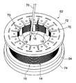
- the alignment jig 62 includes a ring-shaped lower plate 64 and a plurality of (here, 16) guide pins 68 (pilot pins) protruding upward from the lower plate 64. ) And a plurality (eight in this case) of columns 70 projecting upward from the alignment jig 62.
- pillars 70 can be changed suitably.
- the 16 guide pins 68 are arranged at equal intervals (interval of 22.5 degrees) in the circumferential direction of the lower plate 64, and are firmly fixed to the lower plate 64. Further, the eight struts 70 are arranged at equal intervals (intervals of 45 degrees) in the circumferential direction of the lower plate 64 on the inner peripheral side of the lower plate 64 relative to the 16 guide pins 68, and are firmly attached to the lower plate 64. It is fixed to.
- the alignment jig 62 includes the ring-shaped upper plate 72 shown in FIG. 8, but is used in a state where the upper plate 72 is removed in the stacking process.
- the arcuate core pieces 12 pushed onto the alignment jig 62 are held on the alignment jig 62 with the guide pins 68 inserted into the four guide holes 24, respectively.
- the alignment jig 62 is rotated about the vertical axis by the rotary table 60 of the electric index machine 48 in conjunction with the feed feeder 42 and the servo press 46 and is lowered by the ROBO cylinder 50 at a predetermined timing.
- the aligning jig 62 is shown in FIG. Is rotated 90 degrees (the arc angle ⁇ of the arc-shaped core piece 12) in the direction of arrow B of 5. By repeating this 90-degree rotation three times, one layer of the core piece 14 is completed.
- the alignment jig 62 is lowered by the thickness of the arc-shaped iron core piece 12 by the ROBO cylinder 50 and rotated 22.5 degrees (phase shift angle ⁇ ) in the direction of arrow B in FIG. Is done.
- the plurality of annular core pieces 14 are laminated (rotated and laminated) with the phases shifted in the circumferential direction, and the laminated core body 16 is manufactured. Then, the manufactured laminated core body 16 is removed from the turntable 60 together with the alignment jig 62, and the process proceeds to the next pressing step.
- the arc-shaped cores of the respective layers whose phases are shifted in the circumferential direction at a plurality of portions arranged in the circumferential direction in the inner circumferential portion of the laminated core body 16 (here, 16 locations: refer to the welded portions 18 in FIGS. 1 and 3).
- the pieces 12 are welded along the stacking direction.
- the upper plate 72 is attached to the alignment jig 62.
- the upper plate 72 is fixed to the upper ends of the eight columns 70 by, for example, bolt fastening, and holds the laminated core body 16 at a predetermined thickness.
- the laminated core body 16 is held at a predetermined thickness by a dedicated holding device that holds the upper plate 72 and the lower plate 64 up and down with eight columns 70 interposed therebetween.
- the alignment jig 62 is mounted on a turntable 74 (see FIG. 8) included in the fiber laser welder, and the above-mentioned welding is performed by the fiber laser welder (note that reference numeral 76 is attached in FIG. 8).
- the member is a torch of a fiber laser welder).
- the laminated iron core 10 is manufactured by the press process, the lamination process, and the welding process described above.
- the laminated core body 16 is formed by laminating a plurality of annular core pieces 14 each constituted by a plurality of circular arc-shaped core pieces 12 arranged in a ring with a phase shifted in the circumferential direction.
- a plurality of welded portions 18 are arranged in the circumferential direction on the inner peripheral portion of the laminated core body 16.
- the arc-shaped core pieces 12 of the respective layers that are out of phase in the circumferential direction are welded along the stacking direction.
- the arc-shaped core pieces 12 of each layer can be integrally joined, and therefore no dedicated equipment for simultaneously performing caulking and stacking is required. As a result, the manufacturing cost can be reduced.
- the cost of the mold can be greatly reduced.
- a dedicated press machine for simultaneously performing pressing and rotary lamination is unnecessary, a standard press machine can be used, and the cost of the press machine can be greatly reduced.
- the equipment can be made much cheaper than the conventional method.
- it can be dealt with by adding a relatively inexpensive laminated assembly device 38, which is preferable.
- the outer peripheral portion of the laminated core body 16 is provided with a plurality of magnet mounting portions 20 provided on the outer peripheral portion of the plurality of arc-shaped core pieces 12, while the inner periphery of the laminated core body 16 is arranged.
- the part is provided with a plurality of welds 18. Thereby, it can suppress that a welding distortion arises in the magnet mounting part 20 with the heat
- the arc-shaped iron core piece 12 is formed with the guide hole 24 into which the guide pin 68 provided in the alignment jig 62 used at the time of lamination and welding is inserted.
- the magnet mounting part 20 and the magnet mounting part 20 are located on the opposite sides of each other through the guide hole 24. Thereby, it can suppress that the heat at the time of welding the welding part 18 is transmitted to the magnet mounting part 20.
- FIG. the heat can be transmitted to the alignment jig 62 via the guide pins 68 inserted into the guide holes 24. As a result, it is possible to effectively suppress welding distortion from occurring in the magnet mounting portion 20.
- the arc-shaped core pieces 12 of each layer are welded in the stacking direction by the same number of welding portions 18 as the number of magnetic poles of the laminated core body 16 (the number of magnet mounting portions 20 provided in one annular core piece 14). ing. Thereby, the arc-shaped core pieces 12 of each layer can be firmly bonded.
- the pressing process and the laminating process are separate processes, it is not necessary to match the production speed of one process with the production speed of the other process. Thereby, the productivity of a process with a high production speed can be improved.
- the laminated core main body 16 was set as the structure made into 16 poles, this invention is not limited to this, The number of the magnetic poles of the laminated core main body 16 can be changed suitably.
- the number of welds 18 is the same as the number of magnetic poles of the laminated core body 16.
- the present invention is not limited to this, and the number of welds can be changed as appropriate.
- a configuration may be employed in which half the number of magnetic poles of the laminated core body is provided.
Landscapes
- Engineering & Computer Science (AREA)
- Manufacturing & Machinery (AREA)
- Power Engineering (AREA)
- Manufacture Of Motors, Generators (AREA)
Abstract
製造コストを低減する。 積層鉄心(10)の製造方法では、環状に並ぶ複数の円弧状鉄心片(12)によって各々が構成された複数の環状鉄心片(14)が、周方向に位相をずらして積層され、積層鉄心本体(16)が製造される。次いで、この積層鉄心本体(16)の内周部又は外周部における周方向に並ぶ複数の部位(複数の溶接部(18))において、周方向に位相ずれした各層の円弧状鉄心片(12)が積層方向に沿って溶接される。これにより、各層の円弧状鉄心片(12)を一体的に結合することができるので、かしめと積層を同時に行うための専用設備が不要になる。その結果、製造コストを低減することができる。
Description
本発明は、車両駆動用モータの積層鉄心の製造方法に関する。
特開2013-5628号公報には、環状に並ぶ複数のセグメント鉄心片からなる環状鉄心片が、順次かしめ積層されることにより形成された積層鉄心が記載されている。
上述の如き積層鉄心では、かしめと積層を同時に行うための専用設備が高価であるため、製造コストを低減する観点で改善の余地がある。
本発明は上記事実を考慮し、製造コストを低減することができる車両駆動用モータの積層鉄心の製造方法を得ることを目的とする。
本発明に係る車両駆動用モータの積層鉄心の製造方法は、帯状の磁性鋼板をプレス加工することにより、複数の円弧状鉄心片を連結部で連結したキャリア付き単板を製造するプレス工程と、搬送される前記キャリア付き単板から前記円弧状鉄心片を順次切り離すと共に、切り離した前記円弧状鉄心片を環状に並べて環状鉄心片を形成しつつ、複数の前記環状鉄心片を周方向に位相をずらして積層することにより積層鉄心本体を製造する積層工程と、前記積層鉄心本体の内周部又は外周部における周方向に並ぶ複数の部位において、周方向に位相ずれした各層の前記円弧状鉄心片を積層方向に沿って溶接する溶接工程と、を有している。
本発明では、上記のプレス工程、積層工程及び溶接工程によって車両駆動用モータの積層鉄心を製造することができるので、かしめと積層を同時に行うための専用設備が不要になる。その結果、製造コストを低減することができる。しかも、プレス工程と積層工程とが別工程とされているため、一方の工程の生産スピードに他方の工程の生産スピードを合わせる必要がない。それにより、生産スピードが速い工程の生産性を向上させることができる。
以上説明したように、本発明に係る車両駆動用モータの積層鉄心の製造方法では、製造コストを低減することができる。
以下、図1~図8を用いて本発明の実施形態に係る車両駆動用モータの積層鉄心の製造方法について説明する。
(積層鉄心の構成)
先ず、本実施形態に係る車両用駆動モータの積層鉄心の製造方法によって製造された積層鉄心10について説明する。この積層鉄心10は、車両駆動用モータ(電動機)の回転子側に用いられる積層回転子鉄心であり、磁石付き回転子の構成要素である。この積層鉄心10は、図1に示すように、4つに分割された円弧状鉄心片12(分割鉄心片)を環状に並べた環状鉄心片14を複数積層して構成された積層鉄心本体16が、複数の溶接部18によって一体化されることにより形成されている。
先ず、本実施形態に係る車両用駆動モータの積層鉄心の製造方法によって製造された積層鉄心10について説明する。この積層鉄心10は、車両駆動用モータ(電動機)の回転子側に用いられる積層回転子鉄心であり、磁石付き回転子の構成要素である。この積層鉄心10は、図1に示すように、4つに分割された円弧状鉄心片12(分割鉄心片)を環状に並べた環状鉄心片14を複数積層して構成された積層鉄心本体16が、複数の溶接部18によって一体化されることにより形成されている。
各円弧状鉄心片12は、本実施形態では円弧角θが90度に設定されている。各円弧状鉄心片12の外周部には、周方向に並ぶ複数(ここでは4つ)の円弧状の磁石装着部20(磁極片部)が形成されている。これらの磁石装着部20は、円弧角δが22.5度に設定されており、各磁石装着部20には、磁石を装着するための磁石装着孔22が形成されている。
また、各円弧状鉄心片12の幅方向中間部(外周と内周との間の中間部)には、各環状鉄心片14の周方向に並ぶ複数(ここでは4つ)の円形のガイド孔24が形成されている。これらのガイド孔24は、複数の環状鉄心片14の積層時及び積層鉄心本体16の溶接時に用いられる整列治具62(図7及び図8参照)に設けられたガイドピン68を挿入するためのパイロット孔である。
上記のガイド孔24および磁石装着部20は、円弧状鉄心片12を環状に並べて環状鉄心片14を構成した状態で、22.5度毎に配置されるように設けられており、上記のガイド孔24は、環状鉄心片14の周方向において磁石装着部20と同位相で設けられている。
互いに重なる環状鉄心片14は、図2に示されるように、周方向の円弧状鉄心片12同士の繋ぎ目26が周方向に位相ずれされて、いわゆるレンガ積みに所定枚数積層されている。そして、本実施形態では、上記の位相ずれ角が、磁石装着部20の円弧角δと同じ22.5度に設定されている。
22.5度の位相ずれを有して環状鉄心片14を積層すると、磁石装着部20およびガイド孔24が22.5度毎に配置されているため、磁石装着部20およびガイド孔24のそれぞれの位置が、積層方向に一致する。したがって、磁石装着部20およびガイド孔24は、積層鉄心本体16の軸線方向一端側から軸線方向他端側へ貫通する。
上記の如く積層された複数の環状鉄心片14を一体化する複数の溶接部18は、積層鉄心本体16の内周部に周方向に並んで設けられている。これら複数の溶接部18は、本実施形態では、積層鉄心本体16の磁極数と同数(ここでは16極)設けられており、周方向に位相ずれした各層の円弧状鉄心片12を積層方向に沿って溶接(接合)している。
上記複数の溶接部18は、ガイド孔24を介して磁石装着部20とは反対側に位置しており、積層鉄心本体16の内周部に22.5度毎に設けられている。
(積層鉄心10の製造方法)
次に、上記構成の積層鉄心10の製造方法について説明する。
次に、上記構成の積層鉄心10の製造方法について説明する。
積層鉄心10の製造方法は、第1工程であるプレス工程と、第2工程である積層工程と、第3工程である溶接工程と、第4工程である検査工程とによって構成されている。
プレス工程においては、帯状の磁性鋼板を、金型装置によりプレス加工することにより、複数の円弧状鉄心片12を一対の連結部32で連結したキャリア付き単板30(図4~図6参照)を製造する。そして、製造したキャリア付き単板30をリール34(図4参照)に巻き回し、次工程の積層工程へと移行する。
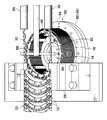
積層工程では、搬送されるキャリア付き単板30から円弧状鉄心片12を順次切り離すと共に、切り離した円弧状鉄心片12を環状に並べて環状鉄心片14を形成しつつ、複数の環状鉄心片14を周方向に位相をずらして積層することにより積層鉄心本体16を製造する。具体的には、先ず、図4に示されるリールスタンド36にリール34を取り付けると共に、リール34に巻き回されたキャリア付き単板30を解いて図4及び図5に示される積層組立装置38の案内ローラ40に巻きかけ、当該積層組立装置38内に挿入する。
積層組立装置38内には、送りフィーダー42、サーボプレス46、電気式インデックス機48、ロボシリンダー50、及びこれらの作動を制御する制御盤52が設けられている。送りフィーダー42は、積層組立装置38内に挿入されたキャリア付き単板30を保持してサーボプレス46および電気式インデックス機48側へ搬送する。なお、図4及び図5に矢印Aで示される方向が、キャリア付き単板30の搬送方向である。
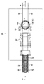
サーボプレス46には、つなぎ部カット型のパンチ54が取り付けられており、当該パンチ54の下方側に配設されたつなぎ部カット型のダイス56との間で、搬送されるキャリア付き単板30の連結部32から円弧状鉄心片12が順次切り離される。なお、円弧状鉄心片12が切り離された連結部32は、図6に示される搬送パイプ58(図4及び図5では図示省略)内を通って積層組立装置38外へ排出され、図示しないスクラップカット機へと搬送される。
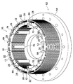
切り離された円弧状鉄心片12は、電気式インデックス機48の回転台60上に着脱可能に取り付けられた整列治具62上に、上記のパンチ54によって押し込まれる。この整列治具62は、図6及び図7に示されるように、リング形の下板64と、当該下板64から上方へ突出した複数本(ここでは16本)のガイドピン68(パイロットピン)と、整列治具62から上方へ突出した複数本(ここでは8本)の支柱70とを備えている。なお、ガイドピン68及び支柱70の数は適宜変更可能である。
16本のガイドピン68は、下板64の周方向に等間隔(22.5度の間隔)に並んでおり、下板64に強固に固定されている。また、8本の支柱70は、16本のガイドピン68よりも下板64の内周側で下板64の周方向に等間隔(45度の間隔)に並んでおり、下板64に強固に固定されている。なお、この整列治具62は、図8に示されるリング形の上板72を含んで構成されているが、積層工程では上板72が取り外された状態で使用される。
上記の整列治具62上に押し込まれた円弧状鉄心片12は、4つのガイド孔24にそれぞれガイドピン68が挿入された状態で整列治具62上に保持される。この整列治具62は、電気式インデックス機48の回転台60によって、送りフィーダー42及びサーボプレス46と連動して垂直軸回りに回転されると共に、ロボシリンダー50によって所定のタイミングで下降される。
具体的には、先ず、円弧状鉄心片12を環状に並べて環状鉄心片14を形成すべく、1枚の円弧状鉄心片12が整列治具62上に押し込まれる毎に整列治具62が図5の矢印B方向へ90度(円弧状鉄心片12の円弧角θ)回転される。この90度の回転が3回繰り返されることにより、一層の環状鉄心片14が完成する。次いで、整列治具62がロボシリンダー50によって円弧状鉄心片12の板厚分だけ下降されると共に、電気式インデックス機48によって図5の矢印B方向へ22.5度(位相ずれ角δ)回転される。上記の処理が順次繰り返されることにより、複数の環状鉄心片14が周方向に位相をずらされて積層(回転積層)され、積層鉄心本体16が製造される。そして、製造された積層鉄心本体16を整列治具62ごと回転台60から取り外し、次工程のプレス工程へと移行する。
プレス工程では、積層鉄心本体16の内周部における周方向に並ぶ複数の部位(ここでは16箇所:図1及び図3の溶接部18参照)において、周方向に位相ずれした各層の円弧状鉄心片12を積層方向に沿って溶接する。具体的には、先ず、図8に示されるように、整列治具62に上板72が取り付けられる。この上板72は、例えばボルト締結によって8本の支柱70の上端に固定され、積層鉄心本体16を所定の厚さに保持する。或いは例えば、上板72と下板64を8本の支柱70を間に挟んで上下に挟持する専用の挟持装置によって、積層鉄心本体16を所定の厚さに保持する。
次いで、ファイバーレーザー溶接機が備える回転台74(図8参照)の上に整列治具62が取り付けられ、当該ファイバーレーザー溶接機によって上記の溶接が行われる(なお、図8において符号76が付された部材は、ファイバーレーザー溶接機のトーチである)。これにより、積層鉄心10が完成する。完成した積層鉄心は、次工程の検査工程において所定の検査を受ける。
(作用および効果)
次に、本実施形態の作用及び効果について説明する。
次に、本実施形態の作用及び効果について説明する。
本実施形態では、上述したプレス工程、積層工程及び溶接工程によって積層鉄心10が製造される。この積層鉄心10では、積層鉄心本体16は、環状に並ぶ複数の円弧状鉄心片12によって各々が構成された複数の環状鉄心片14が、周方向に位相をずらして積層されている。この積層鉄心本体16の内周部には、複数の溶接部18が周方向に並んで設けられている。これらの溶接部18においては、周方向に位相ずれした各層の円弧状鉄心片12が積層方向に沿って溶接されている。これにより、各層の円弧状鉄心片12を一体的に結合することができるので、かしめと積層を同時に行うための専用設備が不要になる。その結果、製造コストを低減することができる。
つまり、かしめ工法を用いないため、金型の費用を大幅に低減することができる。また、プレスと回転積層を同時に行うための専用のプレス機が不要であるため、標準的なプレス機を用いることができ、プレス機の費用を大幅に低減することができる。その結果、積層組立装置38と溶接設備を含めても、従来工法よりも大幅に安価な設備とすることができる。また、生産しなければならない積層鉄心10の数量が増加した場合でも、比較的安価な積層組立装置38を追加することにより対応することができるので好適である。
また、本実施形態では、積層鉄心本体16の外周部には、複数の円弧状鉄心片12の外周部に設けられた複数の磁石装着部20が配置される一方、積層鉄心本体16の内周部には、複数の溶接部18が設けられる。これにより、溶接部18を溶接する際の熱によって磁石装着部20に溶接歪が生じることを抑制できる。
さらに、本実施形態では、円弧状鉄心片12には、積層時及び溶接時に用いられる整列治具62に設けられたガイドピン68が挿入されるガイド孔24が形成されており、溶接部18と磁石装着部20とがガイド孔24を介して互いに反対側に位置している。これにより、溶接部18を溶接する際の熱が磁石装着部20に伝達されることを抑制できる。しかも、上記の熱を、ガイド孔24に挿入されたガイドピン68を介して整列治具62に伝達することが可能になる。その結果、磁石装着部20に溶接歪が生じることを効果的に抑制できる。
また、本実施形態では、積層鉄心本体16の磁極数(1の環状鉄心片14が備える磁石装着部20の数)と同数の溶接部18によって各層の円弧状鉄心片12が積層方向に溶接されている。これにより、各層の円弧状鉄心片12を強固に結合することができる。
また、本実施形態では、プレス工程と積層工程とが別工程とされているため、一方の工程の生産スピードに他方の工程の生産スピードを合わせる必要がない。それにより、生産スピードが速い工程の生産性を向上させることができる。
(実施形態の補足説明)
上記実施形態では、積層鉄心本体16が16極とされた構成にしたが、本発明はこれに限らず、積層鉄心本体16の磁極数は適宜変更することができる。
上記実施形態では、積層鉄心本体16が16極とされた構成にしたが、本発明はこれに限らず、積層鉄心本体16の磁極数は適宜変更することができる。
また、上記実施形態では、積層鉄心本体16の磁極数と同数の溶接部18が設けられた構成にしたが、本発明はこれに限らず、溶接部の数は適宜変更することができる。例えば、積層鉄心本体の磁極数の半数の溶接部が設けられる構成にしてもよい。
また、上記実施形態では、溶接部18と磁石装着部20とがガイド孔24を介して互いに反対側に設けられた構成にしたが、本発明はこれに限らず、溶接部とガイド孔とが円弧状鉄心片の周方向にずれて設けられた構成にしてもよい。
また、上記実施形態では、溶接部18が積層鉄心本体16の内周部に設けられた構成にしたが、本発明はこれに限らず、溶接部が積層鉄心本体の外周部に設けられた構成にしてもよい。
その他、本発明は、その要旨を逸脱しない範囲で種々変更して実施できる。また、本発明の権利範囲が上記実施形態に限定されないことは勿論である。
なお、2014年4月17日に出願された日本国特許出願2014-085833号の開示は、その全体が参照により本明細書に取り込まれる。本明細書に記載された全ての文献、特許出願、および技術規格は、個々の文献、特許出願、および技術規格が参照により取り込まれることが具体的かつ個別に記された場合と同程度に、本明細書中に参照により取り込まれる。
Claims (1)
- 帯状の磁性鋼板をプレス加工することにより、複数の円弧状鉄心片を連結部で連結したキャリア付き単板を製造するプレス工程と、
搬送される前記キャリア付き単板から前記円弧状鉄心片を順次切り離すと共に、切り離した前記円弧状鉄心片を環状に並べて環状鉄心片を形成しつつ、複数の前記環状鉄心片を周方向に位相をずらして積層することにより積層鉄心本体を製造する積層工程と、
前記積層鉄心本体の内周部又は外周部における周方向に並ぶ複数の部位において、周方向に位相ずれした各層の前記円弧状鉄心片を積層方向に沿って溶接する溶接工程と、
を有する車両駆動用モータの積層鉄心の製造方法。
Applications Claiming Priority (2)
| Application Number | Priority Date | Filing Date | Title |
|---|---|---|---|
| JP2014085833A JP6469355B2 (ja) | 2014-04-17 | 2014-04-17 | 車両駆動用モータの積層鉄心の製造方法 |
| JP2014-085833 | 2014-04-17 |
Publications (1)
| Publication Number | Publication Date |
|---|---|
| WO2015159985A1 true WO2015159985A1 (ja) | 2015-10-22 |
Family
ID=54324186
Family Applications (1)
| Application Number | Title | Priority Date | Filing Date |
|---|---|---|---|
| PCT/JP2015/061900 Ceased WO2015159985A1 (ja) | 2014-04-17 | 2015-04-17 | 車両駆動用モータの積層鉄心の製造方法 |
Country Status (2)
| Country | Link |
|---|---|
| JP (1) | JP6469355B2 (ja) |
| WO (1) | WO2015159985A1 (ja) |
Cited By (1)
| Publication number | Priority date | Publication date | Assignee | Title |
|---|---|---|---|---|
| WO2024085049A1 (ja) * | 2022-10-19 | 2024-04-25 | 日本発條株式会社 | 積層鉄心の検査方法及び装置並びに補修方法及び装置 |
Families Citing this family (3)
| Publication number | Priority date | Publication date | Assignee | Title |
|---|---|---|---|---|
| JP6891973B2 (ja) | 2017-12-08 | 2021-06-18 | 日産自動車株式会社 | 回転電機の回転子鉄心、及び、回転電機の回転子鉄心の製造方法 |
| CN113491058B (zh) * | 2018-12-28 | 2023-09-26 | 日本发条株式会社 | 层叠铁芯以及层叠铁芯的制造方法 |
| KR102938741B1 (ko) | 2020-09-11 | 2026-03-13 | 엘지이노텍 주식회사 | 스테이터 모듈 정렬 장치 |
Citations (2)
| Publication number | Priority date | Publication date | Assignee | Title |
|---|---|---|---|---|
| JP2000295800A (ja) * | 1999-04-01 | 2000-10-20 | Mitsubishi Electric Corp | 車両用交流発電機の固定子コア及び車両用交流発電機の固定子コアの製造方法 |
| WO2012043632A1 (ja) * | 2010-09-29 | 2012-04-05 | 本田技研工業株式会社 | 積層体製造装置および積層体製造方法 |
Family Cites Families (4)
| Publication number | Priority date | Publication date | Assignee | Title |
|---|---|---|---|---|
| JP5347321B2 (ja) * | 2008-05-01 | 2013-11-20 | 日産自動車株式会社 | 積層鉄心の製造方法および製造装置、並びに積層鉄心 |
| JP2013143872A (ja) * | 2012-01-11 | 2013-07-22 | Aisin Aw Co Ltd | 回転電機のロータコア及びその製造方法 |
| JP6010976B2 (ja) * | 2012-03-30 | 2016-10-19 | 株式会社デンソー | 積層鉄心の製造方法 |
| JP2013226014A (ja) * | 2012-04-23 | 2013-10-31 | Honda Motor Co Ltd | 積層コアの製造方法及び積層コアの製造装置 |
-
2014
- 2014-04-17 JP JP2014085833A patent/JP6469355B2/ja active Active
-
2015
- 2015-04-17 WO PCT/JP2015/061900 patent/WO2015159985A1/ja not_active Ceased
Patent Citations (2)
| Publication number | Priority date | Publication date | Assignee | Title |
|---|---|---|---|---|
| JP2000295800A (ja) * | 1999-04-01 | 2000-10-20 | Mitsubishi Electric Corp | 車両用交流発電機の固定子コア及び車両用交流発電機の固定子コアの製造方法 |
| WO2012043632A1 (ja) * | 2010-09-29 | 2012-04-05 | 本田技研工業株式会社 | 積層体製造装置および積層体製造方法 |
Cited By (2)
| Publication number | Priority date | Publication date | Assignee | Title |
|---|---|---|---|---|
| WO2024085049A1 (ja) * | 2022-10-19 | 2024-04-25 | 日本発條株式会社 | 積層鉄心の検査方法及び装置並びに補修方法及び装置 |
| JP7542786B1 (ja) * | 2022-10-19 | 2024-08-30 | 日本発條株式会社 | 積層鉄心の検査方法及び装置並びに補修方法及び装置 |
Also Published As
| Publication number | Publication date |
|---|---|
| JP2015208066A (ja) | 2015-11-19 |
| JP6469355B2 (ja) | 2019-02-13 |
Similar Documents
| Publication | Publication Date | Title |
|---|---|---|
| JP6486930B2 (ja) | 車両駆動用モータの積層鉄心の製造方法 | |
| JP6653560B2 (ja) | 固定子積層鉄心及びその製造方法 | |
| JP6469355B2 (ja) | 車両駆動用モータの積層鉄心の製造方法 | |
| US9553495B2 (en) | Wound core, electromagnetic component and manufacturing method therefor, and electromagnetic equipment | |
| JP5971418B2 (ja) | 回転電機用同期ロータと回転電機用同期ロータの製造方法 | |
| JP6343557B2 (ja) | 回転子用積層体及びその製造方法並びに回転子の製造方法 | |
| JP5356897B2 (ja) | 回転電機及びその製造方法 | |
| JP6401605B2 (ja) | ダミーカシメを有する積層体及びその製造方法、並びに積層鉄心の製造方法 | |
| CN112134426B (zh) | 铁芯产品的制造方法及铁芯产品 | |
| JP2013090386A (ja) | 回転電機用コアの製造方法及びコア板の打ち抜き装置 | |
| JP6965465B2 (ja) | 積層鉄心及び積層鉄心の製造方法 | |
| JP2019103219A (ja) | 回転電機および回転電機の製造方法 | |
| JP6400458B2 (ja) | 打抜き方法及び積層鉄心の製造方法 | |
| JP7046265B2 (ja) | 電機子鉄心の製造方法、電気機械の製造方法、及び電気機械 | |
| JP5717555B2 (ja) | 固定子鉄心 | |
| JP6917325B2 (ja) | 車両駆動用モータの積層鉄心の製造方法及び積層鉄心 | |
| JP2019161984A (ja) | 回転体の製造方法 | |
| CN111247714A (zh) | 旋转电机的电枢铁芯、铁芯块连结体以及旋转电机的电枢铁芯的制造方法 | |
| KR101720673B1 (ko) | 복합재료를 이용하는 분할코어 및 그의 제조방법 | |
| JP2021093789A (ja) | 回転電機のステータ、及び回転電機のステータの製造方法 | |
| JP2024060339A (ja) | 積層鉄心及びその製造方法 | |
| KR100519114B1 (ko) | 리니어 모터용 코어의 제조방법 | |
| WO2018074088A1 (ja) | 回転電機のステータとその製造方法 | |
| CN111264016A (zh) | 铁芯块连结体以及旋转电机的电枢铁芯的制造方法 |
Legal Events
| Date | Code | Title | Description |
|---|---|---|---|
| 121 | Ep: the epo has been informed by wipo that ep was designated in this application |
Ref document number: 15780389 Country of ref document: EP Kind code of ref document: A1 |
|
| NENP | Non-entry into the national phase |
Ref country code: DE |
|
| 122 | Ep: pct application non-entry in european phase |
Ref document number: 15780389 Country of ref document: EP Kind code of ref document: A1 |