WO2015159897A1 - 切削インサート、工具ボデー及び刃先交換式回転切削工具 - Google Patents
切削インサート、工具ボデー及び刃先交換式回転切削工具 Download PDFInfo
- Publication number
- WO2015159897A1 WO2015159897A1 PCT/JP2015/061512 JP2015061512W WO2015159897A1 WO 2015159897 A1 WO2015159897 A1 WO 2015159897A1 JP 2015061512 W JP2015061512 W JP 2015061512W WO 2015159897 A1 WO2015159897 A1 WO 2015159897A1
- Authority
- WO
- WIPO (PCT)
- Prior art keywords
- cutting
- insert
- wall surface
- tool
- side wall
- Prior art date
- Legal status (The legal status is an assumption and is not a legal conclusion. Google has not performed a legal analysis and makes no representation as to the accuracy of the status listed.)
- Ceased
Links
Images








Classifications
-
- B—PERFORMING OPERATIONS; TRANSPORTING
- B23—MACHINE TOOLS; METAL-WORKING NOT OTHERWISE PROVIDED FOR
- B23C—MILLING
- B23C5/00—Milling-cutters
- B23C5/02—Milling-cutters characterised by the shape of the cutter
- B23C5/06—Face-milling cutters, i.e. having only or primarily a substantially flat cutting surface
-
- B—PERFORMING OPERATIONS; TRANSPORTING
- B23—MACHINE TOOLS; METAL-WORKING NOT OTHERWISE PROVIDED FOR
- B23C—MILLING
- B23C5/00—Milling-cutters
- B23C5/16—Milling-cutters characterised by physical features other than shape
- B23C5/20—Milling-cutters characterised by physical features other than shape with removable cutter bits or teeth or cutting inserts
- B23C5/22—Securing arrangements for bits or teeth or cutting inserts
- B23C5/2204—Securing arrangements for bits or teeth or cutting inserts with cutting inserts clamped against the walls of the recess in the cutter body by a clamping member acting upon the wall of a hole in the insert
- B23C5/2208—Securing arrangements for bits or teeth or cutting inserts with cutting inserts clamped against the walls of the recess in the cutter body by a clamping member acting upon the wall of a hole in the insert for plate-like cutting inserts
- B23C5/2213—Securing arrangements for bits or teeth or cutting inserts with cutting inserts clamped against the walls of the recess in the cutter body by a clamping member acting upon the wall of a hole in the insert for plate-like cutting inserts having a special shape
-
- B—PERFORMING OPERATIONS; TRANSPORTING
- B23—MACHINE TOOLS; METAL-WORKING NOT OTHERWISE PROVIDED FOR
- B23C—MILLING
- B23C2200/00—Details of milling cutting inserts
- B23C2200/04—Overall shape
- B23C2200/045—Round
-
- B—PERFORMING OPERATIONS; TRANSPORTING
- B23—MACHINE TOOLS; METAL-WORKING NOT OTHERWISE PROVIDED FOR
- B23C—MILLING
- B23C2200/00—Details of milling cutting inserts
- B23C2200/04—Overall shape
- B23C2200/0455—Square
- B23C2200/0461—Square rounded
-
- B—PERFORMING OPERATIONS; TRANSPORTING
- B23—MACHINE TOOLS; METAL-WORKING NOT OTHERWISE PROVIDED FOR
- B23C—MILLING
- B23C2200/00—Details of milling cutting inserts
- B23C2200/12—Side or flank surfaces
- B23C2200/128—Side or flank surfaces with one or more grooves
-
- B—PERFORMING OPERATIONS; TRANSPORTING
- B23—MACHINE TOOLS; METAL-WORKING NOT OTHERWISE PROVIDED FOR
- B23C—MILLING
- B23C2200/00—Details of milling cutting inserts
- B23C2200/20—Top or side views of the cutting edge
- B23C2200/203—Curved cutting edges
-
- B—PERFORMING OPERATIONS; TRANSPORTING
- B23—MACHINE TOOLS; METAL-WORKING NOT OTHERWISE PROVIDED FOR
- B23C—MILLING
- B23C2210/00—Details of milling cutters
- B23C2210/16—Fixation of inserts or cutting bits in the tool
- B23C2210/168—Seats for cutting inserts, supports for replacable cutting bits
Definitions
- the present invention relates to a cutting insert, a tool body, and a cutting edge exchange type rotary cutting tool. More specifically, the present invention relates to a cutting insert having a substantially circular outer shape in plan view, a tool body to which the cutting insert can be mounted, and a blade edge replacement to which the cutting insert is detachably mounted. And a rotary cutting tool.
- a blade cutter replaceable type radius cutter using a cutting insert having a circular or substantially circular outer shape in plan view Such a cutting insert has a cutting edge that is curved in an arc shape at an intersection ridge line portion between the upper surface or the lower surface and the side surface.
- this type of cutting insert it is possible to sequentially index cutting edges used for cutting into unused cutting edges by rotating the cutting insert around an axis.
- Patent Document 1 An example of a radial cutter using such a cutting insert is disclosed in Patent Document 1.
- the upper surface is not completely circular in a plan view, and arc-shaped curved portions having relatively long lengths and linear portions having relatively short lengths are alternately continued. It has a shape.
- Four arcuate curved portions and four straight portions are formed so as to be 90 ° rotationally symmetric about the center axis of the cutting insert. That is, the arcuate curved portion and the straight portion are provided at 90 ° intervals with the central axis as the center.
- the arcuate curved portion functions as a main cutting edge
- the straight portion functions as a sub-cutting edge (sweeper blade).
- the linear sub-cutting edge is disposed so as to be located closest to the tool tip side in the position along the center axis of the tool body, that is, the position where the machining bottom surface of the work material is cut.
- the cutting insert of patent document 1 has four sets of the main cutting edge and the sub-cutting edge, it is possible to index a cutting edge 4 times.
- the cutting insert of patent document 1 has the restraint part comprised from the plane in the side part directly under each sub-cutting edge in side view.
- the flat restraining portion comes into contact with the corresponding side surface portion of the insert seat.
- the insert seat has two side portions. One side surface portion is positioned on the most proximal side in the direction parallel to the center axis of the tool body in the side view of the tool body, and the other side surface portion is the most in the direction perpendicular to the center axis line of the tool body.
- the working auxiliary cutting edge is surely positioned closest to the tool tip side in the direction along the central axis of the tool body by firmly contacting the restraint portion of the cutting insert and the side surface portion of the insert seat with each other. Therefore, the cutting edge can be easily indexed by rotating the cutting insert.
- the radius cutter of Patent Document 1 has the following problems.
- the main cutting edge is curved in an arc shape as described above.
- the cutting force (combined force) applied to the main cutting edge is usually not directed in a direction perpendicular to the central axis of the tool body. That is, when the cutting insert attached to the insert seat is viewed from the direction facing it, the cutting force may be directed between the direction perpendicular to the central axis and the direction of the base end side of the tool body on the central axis. It is common.
- one side surface portion of the insert seat is arranged in a direction perpendicular to the central axis of the tool body.
- an arcuate cutting edge (that is, an inner cutting edge) arranged on the center axis side of the tool body is also involved in the cutting.
- the same situation as in the case of the main cutting edge described above occurs with respect to the cutting resistance applied to the inner cutting edge. That is, neither of the two side surfaces of the insert seat is arranged at a position where the cutting force applied to the inner blade can be sufficiently received.
- the present invention has been made in view of the above problems, and provides a substantially circular cutting insert, a tool body, and a blade-tip-exchange-type rotary cutting tool that can sufficiently improve the fixing property of the cutting insert in the tool body.
- the purpose is to provide.
- the first end surface has an outer shape in which a plurality of arc-shaped curved portions and the same number of linear portions as the arc-shaped curved portions are alternately arranged, and the arc-shaped curved portions and the linear portions are
- Each of the first end faces is configured to be capable of functioning as a cutting edge, and the first end face has a shape that is n times rotationally symmetric around a central axis that is defined to penetrate the first end face and the second end face.
- a plurality of restraining portions are provided on the peripheral side surface, Each constraining part is provided with a cutting insert located on the opposite side of the corresponding arcuate curved part across the central axis.
- each constraining portion on the peripheral side surface is located on the opposite side of the corresponding arcuate curved portion across the central axis. Therefore, when the arcuate curved portion acts as a cutting edge in the cutting edge-exchangeable cutting tool to which this cutting insert is attached, the cutting resistance applied to the working cutting edge is set to the opposite side of the working cutting edge across the central axis. It can be effectively received by the wall surface portion of the tool body that comes into contact with a certain restraining portion. Therefore, according to one aspect of the present invention, the fixing property of the cutting insert is improved, and the cutting performance and tool life are improved.
- the virtual line obtained by projecting any one of the straight portions and the most Positional relationship in which an intersecting line that cuts the restraining part or an extension line thereof and an imaginary line or an extension line that projects the straight line part intersect with any one restraining part that is in a close position It is in.
- one of the imaginary lines projected from the straight portion and the closest to it A crossing line or an extension line obtained by cutting the restriction part and a virtual line or an extension line obtained by projecting the straight part may be in a substantially parallel positional relationship with one restriction part at a position. .
- the second end surface has an outer shell shape in which a plurality of arc-shaped curved portions and a plurality of linear portions are alternately arranged, and the cutting insert is divided into two equal parts with respect to the central axis.
- an orthogonal virtual plane is defined as an intermediate plane M
- the second end surface has a shape symmetrical to the first end surface with respect to the intermediate plane.
- Each of the plurality of restricting portions may include a first surface portion and a second surface portion that are symmetrical with respect to the intermediate plane. In one restraint portion, the first surface portion may form an obtuse angle with the second surface portion outside the cutting insert.
- the present invention also exists in a tool body.
- a tool body for a cutting edge replaceable rotary cutting tool that includes at least one insert seat, and the cutting insert is detachably attached to the insert seat
- the insert seat has a tool rotation direction.
- a side wall surface intersecting the bottom wall surface at a certain angle the side wall surface being a first side wall surface facing the front end side and the outer peripheral surface side of the tool body, and the tool
- a second side wall surface facing the front end side of the body and the tool center axis side, and the first side wall surface and the second side wall surface are respectively when the cutting insert is mounted on the insert seat.
- a tool body is provided that is configured to be capable of abutting against a corresponding restraining portion.
- the present invention also exists in a blade cutting type rotary cutting tool.
- a tool body having a tool center axis, at least one insert seat formed on the tool body, and a cutting insert detachably mounted on the insert seat.
- the insert seat has a bottom wall surface facing the tool rotation direction, and a side wall surface intersecting the bottom wall surface at a certain angle, and the side wall surface is A first side wall surface facing the distal end side and the outer peripheral surface side of the tool body, and a second side wall surface facing the distal end side of the tool body and the tool center axis, and the cutting insert is attached to the insert seat
- the first side wall surface comes into contact with one corresponding restraining portion
- the second side wall surface comes into contact with another restraining portion different from the restraining portion with which the first side wall surface comes into contact.
- Each of the plurality of constraining portions includes a first surface portion and a second surface portion that are symmetrical with respect to the intermediate plane, and when the first surface portion forms an obtuse angle with the second surface portion outside the cutting insert, When the cutting insert is attached to the insert seat, the first side wall surface abuts only one of the first surface portion and the second surface portion of the restraining portion, and the second side wall surface is the first surface portion of the restraining portion. And only the second surface portion may be in contact with each other.
- FIG. 1 shows a perspective view of a cutting insert according to an embodiment of the present invention.
- FIG. 2 shows a plan view of the cutting insert of FIG.
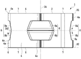
- FIG. 3 shows a side view of the cutting insert of FIG.
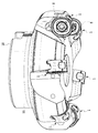
- FIG. 4 shows a perspective view of a blade-exchange-type rotary cutting tool according to an embodiment of the present invention provided with the cutting insert of FIG.
- FIG. 5 is a tool body according to an embodiment of the present invention, and shows a perspective view of the tool body of the cutting edge exchange type rotary cutting tool of FIG. 6 shows an enlarged view of the vicinity of one insert seat of the tool body of FIG. 7A is a partially enlarged view of the cutting tool of FIG.
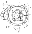
- FIG. 7B is a cross-sectional view taken along line VIIB-VIIB in FIG. 7A.
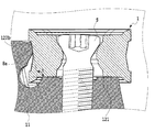
- FIG. 7C is a cross-sectional view taken along line VIIC-VIIC in FIG. 7A.
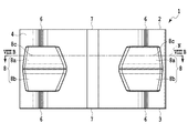
- 8A is a side view of the cutting insert of FIG. 1 and is a view as seen from a side different from FIG. 3.
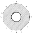
- 8B is a cross-sectional view of the cutting insert of FIG. 1 taken along the line VIIIB-VIIIB of FIG. 8A.
- FIG. 9 shows a perspective view of a cutting insert according to another embodiment of the present invention.
- FIG. 10 shows a plan view of the cutting insert of FIG.
- FIG. 11A shows a side view of the cutting insert of FIG.
- FIG. 11B is a cross-sectional view of the cutting insert of FIG. 9 taken along line XIB-XIB of FIG. 11A.
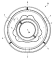
- 12 is a partially enlarged view of the rotary cutting tool with the cutting edge exchange type attached with the cutting insert of FIG. 9 as viewed from the side facing the cutting insert, and the cutting resistance and the insert seat applied to the cutting edge of the cutting insert of FIG. It is a figure for demonstrating the relationship with the side wall surface.
- the cutting insert 1 of this embodiment is shown in FIGS.
- the cutting insert 1 has a first end surface 2 that is substantially circular in a plan view (FIG. 2 when the cutting insert 1 is viewed from the side facing the first end surface 2), a shape similar to the first end surface 2, and a first shape. It basically includes a second end surface 3 disposed so as to face the one end surface 2, and a peripheral side surface 4 connecting the first end surface 2 and the second end surface 3.
- An attachment hole 5 that penetrates the first end surface 2 and the second end surface 3 is provided at the approximate center of the first end surface 2 and the second end surface 3.
- peripheral side surface 4 intersects the first end surface 2 and the second end surface 3 at a substantially right angle (that is, extends substantially parallel to the central axis IA of the mounting hole 5). Therefore, although the cutting insert 1 of this embodiment is what is called a negative type, this invention is not limited to this.
- the first end surface 2 has a substantially circular outer shape in which arc-shaped curved portions 6 and linear portions 7 having a certain curvature are alternately arranged in plan view.
- the outer shape of the first end surface 2 is composed of four arcuate curved portions 6 and four straight portions 7 that are continuous with each other.
- the arcuate curved portion 6 is relatively longer than the straight portion 7.
- the four arcuate curved portions 6 are arranged so as to sandwich the central axis IA of the cutting insert between them, and are arranged so as to be 90 ° rotationally symmetric around the central axis IA.
- the straight portion 7 is also arranged so as to be 90 ° rotationally symmetrical around the central axis IA of the cutting insert 1.
- the arcuate curved portions 6 are arranged at 90 ° intervals with the center axis IA as the center, and the straight portions 7 are also arranged at 90 ° intervals with the center axis IA as the center.
- the lengths of the arcuate curved portion 6 and the straight line portion 7 are not limited to those shown in the drawings, and can be appropriately changed as necessary. Further, the numbers of the arcuate curved portions 6 and the straight portions 7 are not limited to those described above, and can be set as appropriate.
- the central axis IA coincides with the central axis of the mounting hole 5.
- the second end surface 3 has the same outline shape as the first end surface 2.
- the second end face 3 has the same shape, length and number of arcuate curved portions 6 and straight portions 7 as the first end surface 2.
- a virtual plane orthogonal to the central axis IA is defined as an intermediate plane M so as to divide the cutting insert 1 into two equal parts
- the first end surface 2 and the second end surface 3 are symmetrical with respect to the intermediate plane M. It is configured. Therefore, the positions of the arcuate curved portion 6 and the straight portion 7 of the first end surface 2 in the plan view of the cutting insert 1 (FIG. 2) are the bottom view of the cutting insert 2 (not shown) (cut from the side facing the second end surface 3). This corresponds to the positions of the arcuate curved portion 6 and the straight line portion 7 of the second end face 3 in the view of the insert 1.
- the intermediate plane M passes through a central point between the first end surface 2 and the second end surface 3.
- the cutting insert 1 has four arcuate curved portions 6 and four straight portions 7 in each of the first end surface 2 and the second end surface 3 and is 90 ° rotationally symmetric around the central axis IA (4 (Rotational symmetry).
- the arcuate curved portion 6 has a certain curvature as described above in each of the plan view and the bottom view of the cutting insert.
- the linear part 7 is extended linearly in each of planar view and bottom view of the cutting insert.
- each of the circular-arc-shaped curve part 6 and the linear part 7 in each end surface 2 and 3 is extended along the virtual planes P1 and P2 orthogonal to the central axis IA (FIG. 3).
- the present invention does not exclude a cutting insert in which one or both of the arcuate curved portion 6 and the straight portion 7 are curved in the direction of the central axis IA or inclined with respect to a virtual plane perpendicular to the central axis IA.
- the cutting insert 1 of this embodiment is a double-sided use type having cutting edges on both the first end surface 2 and the second end surface 3.
- the intersecting ridge line portion corresponding to the arcuate curved portion 6 can function as a main cutting edge
- the intersecting ridge line portion corresponding to the straight line portion 7 can function as a secondary cutting edge (sieving blade).
- the main cutting edge is a cutting edge in charge of cutting on the side surface side of the workpiece processing surface
- the secondary cutting edge is a cutting blade in charge of cutting on the bottom surface side of the workpiece processing surface.
- the arcuate curved portion 6 is configured to function as a main cutting edge
- the linear portion 7 is configured to function as a secondary cutting edge, so that the arcuate curved portion 6 functions as a main cutting edge.
- the symbol “6” is used for the main cutting edge
- the linear portion 7 functions as a sub cutting edge
- the symbol “7” is used for the sub cutting edge.
- the second end surface 3 when the cutting edge formed on the second end surface 3 side is involved in cutting, the second end surface 3 functions as a rake surface, and the first end surface 2 functions as a seating surface.
- the seating surface means a portion that comes into contact with the bottom wall surface 121 of the insert seat 12 of the tool body 11 to be described later.
- each end surface of the cutting insert 1 has the four arcuate curved portions 6 and the four straight portions 7, and therefore, a set of cutting edges (cutting blade section) is used four times for each end surface. It is possible.
- a cutting insert with a complete circular end face there is no distinction of a main cutting edge and a secondary cutting edge, whereas a part of the arc-shaped cutting edge cuts the bottom side of the work surface of the work material
- the linear sub-cutting edge 7 cuts the bottom surface side of the processed surface of the work material. Therefore, according to the cutting insert 1, the surface roughness of the processed bottom surface of the work material is better than that of a complete circular cutting insert. Therefore, the cutting insert 1 with the secondary cutting edge 7 as in this embodiment is arranged on the tool body 11 so that the linear working secondary cutting edge 7 always cuts the bottom surface side of the processing surface of the work material. Is required.
- the peripheral side surface 4 is formed with a constraining portion 8 that is recessed in a concave shape toward the inner side (center axis IA side) of the cutting insert 1 in an intermediate region between the first end surface 2 and the second end surface 3.
- the restraint portion 8 is clearly shown in a side view (FIG. 3) of the cutting insert 1.
- the restraint portion 8 is a portion of the peripheral side surface 4 configured to contact the side wall surface 122 of the insert seat 12 of the tool body 11.
- the restraining portion 8 includes two surface portions (a first surface portion and a second surface portion).
- the 1st plane 8a as a 1st surface part inclines inward of the cutting insert 1 toward the 2nd end surface 3 side from the 1st end surface 2 side.
- the 2nd plane 8b as a 2nd surface part inclines inward of the cutting insert 1 toward the 1st end surface 2 side from the 2nd end surface 3 side.
- the first plane 8a is connected to the second plane 8b.
- the first plane 8a and the second plane 8b are formed so as to be symmetric with respect to the above-described intermediate plane M.
- the first plane 8a is located in a region on the first end face 2 side of the intermediate plane M, and extends to form an acute angle with the intermediate plane M outside the cutting insert 1 (in FIG. 3, an angle ⁇ ⁇ 90). °).
- the second plane 8b is located in a region on the second end face 3 side of the intermediate plane M and extends so as to form an acute angle with the intermediate plane M outside the cutting insert 1 (angle ⁇ ⁇ 90 in FIG. 3). °).
- the first plane 8a forms an obtuse angle with the second plane 8b outside the cutting insert 1 (90 ° ⁇ + ⁇ ⁇ 180 °).
- the inclination angles of the first and second planes 8a and 8b with respect to the intermediate plane M may be different ( ⁇ ⁇ ⁇ ).
- the first plane 8a may be connected to the second plane 8b via a further plane portion.
- the plurality of restraining portions 8 are peripheral side surfaces 4 between the arcuate curved portion 6 of the first end surface 2 and the arcuate curved portion 6 of the second end surface 3 aligned in the direction of the central axis IA in a side view of the cutting insert 1. Is provided on each side surface portion 4a. Therefore, although the number of the restraint parts 8 provided in the cutting insert 1 of this embodiment is four, naturally this can be suitably changed similarly to the number of the arcuate curved parts 6.
- the restraint part 8 is arrange
- the shape of the restraint part 8 is not limited to what was mentioned above, The other shape which can achieve the objective as the restraint part 8 may be sufficient.
- the first plane 8a and the second plane 8b of the restricting portion 8 can be planes that are substantially perpendicular to the first end face 2 and the second end face 3 (that is, planes parallel to the central axis IA). In this case, the first plane 8a and the second plane 8b constitute one plane, and the restraining portion 8 has only one plane that is symmetrical with respect to the intermediate plane M.
- the cutting insert 1 is configured to be 90 ° rotationally symmetric (four times rotationally symmetric) around the central axis IA. Therefore, when attention is paid to one certain restraining portion 8, this restraining portion 8 is located on the opposite side of one arcuate curved portion 6 on each corresponding end face across the central axis IA.
- FIGS. 1 and 3 Attention is paid to the arcuate curved portion 6z of the first end face 2 on the right back side in FIG.
- an axis IA2 that is orthogonal to the central axis IA and passes through the side surface portion 4z having the arcuate curved portion 6z at the edge is defined and shown.
- the front restraint portion 8z in FIG. 3 through which the axis IA2 passes is a restraint portion located on the opposite side of the corresponding arcuate curved portion 6z across the center axis IA.
- the restraining portion 8 located on the right side in FIG. 3 is a restraining portion 8z
- the side surface portion 4a located on the left side in FIG. 3 becomes the side surface portion 4z.
- the arcuate curved portion 6 at the edge of the side surface portion 4z on the first end surface 2 side is the arcuate curved portion 6z on the opposite side across the central axis IA of the restricting portion 8z.
- the arcuate curved portion 6 at the edge of the side surface portion 4z on the second end surface 3 side is also an arcuate curved portion on the opposite side across the central axis IA of the restricting portion 8z.
- the first end surface 2 is a rake face portion that is inclined so as to approach the intermediate plane M from each of the arcuate curved portion 6 and the straight portion 7 toward the central axis IA of the cutting insert 1. And a boss surface connected to the rake face portion.
- the second end face 3 is connected to the rake face part inclined from the arcuate curved part 6 and the straight line part 7 toward the central axis IA of the cutting insert 1 so as to approach the intermediate plane M, and the rake face part. And a boss surface. More specifically, the first end face 2 will be described.
- the arcuate curved portions are perpendicular to the central axis IA and the arcuate curved portion 6 and the linear portion 7 extend substantially.
- a portion (rake face portion) corresponding to the rake face when 6 and the straight line portion 7 are cutting edges is located on the second end face 3 side.
- the rake face portion is inclined so that the inclination angle of the rake face portion with respect to the virtual plane P1 becomes smaller toward the center axis IA side, and finally connected to a boss surface that can come into contact with the bottom wall surface of the insert seat.
- the boss surface is formed around the through hole and is formed as a flat surface substantially perpendicular to the central axis IA. The same applies to the second end face 3.
- the shape of the 1st end surface 2 or the 2nd end surface 3 is not limited to this, It is possible to change suitably as needed.
- the boss surface is not limited to a flat surface, and may be formed as a curved surface.
- the cutting insert 1 is coated around a hard material such as cemented carbide, cermet, ceramic, or an ultra-high pressure sintered body containing diamond or cubic boron nitride, or the surface of these hard materials. Can be made from the material.
- a hard material such as cemented carbide, cermet, ceramic, or an ultra-high pressure sintered body containing diamond or cubic boron nitride, or the surface of these hard materials. Can be made from the material.
- the cutting edge exchange type rotary cutting tool 10 of the present embodiment is a face mill as shown in FIG.
- the cutting tool 10 includes a tool body 11 on which a plurality of cutting inserts 1 are mounted.
- the cutting tool 10 can be rotated around the tool center axis TA of the tool body 11 extending from the distal end side to the proximal end side and advanced with respect to the work material.
- the cutting insert 1 is mounted on the distal end side of the tool body 11, and the proximal end side of the tool body 11 is a part connected to a machine tool.
- the tool body 11 is formed with a plurality of insert seats 12 provided so as to open to the tool front end side of the outer peripheral surface, and a chip pocket 13 corresponding to each of the insert seats 12.
- the insert seat 12 is a part for fixing the cutting insert 1.
- the chip pocket 13 is a space for discharging chips generated in the cutting process.
- all the insert seats 12 are formed so as to form a certain angle with respect to the bottom wall surface 121 facing the front in the tool rotation direction around the tool center axis TA and the bottom wall surface 121.
- Side wall surface 122 When the cutting insert 1 is mounted on the insert seat 12, the bottom wall surface 121 comes into contact with the boss surface of the first end surface 2 or the second end surface 3 of the cutting insert 1, and the side wall surface 122 is a restraining portion of the peripheral side surface 4 of the cutting insert 1. 8 abuts.
- a screw hole 14 into which the fixing screw S is screwed when the cutting insert 1 is attached with the fixing screw S is provided at the center of the bottom wall surface 121.
- the side wall surface 122 is positioned on the tool outer peripheral side with respect to the first side wall surface 122a positioned on the tool center axis TA side and the first side wall surface 122a.
- Second side wall surface 122b faces the tool outer peripheral direction and the tool tip direction
- the second side wall surface 122b faces the tool center axis TA direction and the tool tip direction.
- the first side wall surface 122a and the second side wall surface 122b are such that each extension line intersects at an angle of about 90 ° when viewed from the direction facing the bottom wall surface 121.
- the cutting insert 1 When the cutting insert 1 is mounted on the insert seat 12, the first side wall surface 122 a and the second side wall surface 122 b of the insert seat 12 and the two adjacent restraining portions 8 provided on the peripheral side surface 4 of the cutting insert 1 are Each abuts against each other.
- the cutting insert 1 is mounted on the insert seat 12 so that a set of cutting edges 6 and 7 formed on the first end face 2 of the cutting insert 1 is involved in cutting.
- the first side wall surface 122a of the insert seat 12 abuts only on the second flat surface 8b on the second end surface 3 side of the single restraining portion 8, and the second side surface 122b of the insert seat 12 is in contact with the first side wall surface 122a. Only the first flat surface 8a on the first end face 2 side of the restraining portion 8 different from the restraining portion 8 that is in contact with the contact portion 8 is in contact. Therefore, the contact portion that contacts the second flat surface 8b of the first side wall surface 122a extends so as to form an acute angle (angle ⁇ in FIG. 7C) with respect to the bottom wall surface 121, and the first flat surface of the second side wall surface 122b.
- the abutting portion that abuts on 8b extends so as to form an obtuse angle (angle ⁇ in FIG. 7B) with respect to the bottom wall surface 121.
- angle ⁇ in FIG. 7B the contact relationship between the first side wall surface 2 and the second side wall surface 3 of the insert seat 12 and the second plane 8b and the first plane 8a of the restraint portion 8 is not limited to this, and as necessary.
- the first side wall surface 122a may abut only on the first plane 8a
- the second side wall surface 122b may abut only on the second plane 8b.
- the restraining surface 8 that contacts the side wall surface 122 of the insert seat 12 can be changed.
- the constraining surface 8 in contact with the insert seat 122 the cutting edge involved in cutting, that is, the arcuate curved portion 6 and the straight portion 7 are also changed. This makes it possible to sequentially determine the cutting edges involved in cutting.
- each of the first end surface 2 and the second end surface 3 of the cutting insert 1 of the present embodiment has a substantially circular outer shape in which four arcuate curved portions 6 and four straight portions 7 are alternately arranged. have.
- the restraining portion 8 of the peripheral side surface 4 is provided on each of the side surface portions 4 a between the arcuate curved portion 6 of the first end surface 2 and the arcuate curved portion 6 of the second end surface 3.
- the one circular-arc-shaped curve part 6 is located in the other side of the one restraint part 8 on both sides of the center axis line IA.
- a tool body having an insert seat 12 including a first side wall surface 122a facing the tool outer peripheral surface direction and the tool tip direction, and a second side wall surface 122b facing the tool center axis TA direction and the tool tip direction.
- the first side wall surface 122a and the second side wall surface 122b are mounted.
- the first side wall surface 122a and the second side wall surface 122b are mounted.
- the first linear portion 7 of the upper surface 2 becomes a sub-cutting edge for cutting the machining bottom surface of the work material (action sub-cutting blade).
- the cutting resistance F1 applied to the arcuate main cutting edge 6 'that is involved in is directed substantially perpendicular to the first side wall surface 122a. Therefore, it is possible for the first side wall surface 122a to reliably receive the largest cutting force applied to the working main cutting edge 6 'among all the cutting resistances applied to the cutting edge. Further, the cutting force F2 applied to the linear action auxiliary cutting edge 7 'acts on the tool base end side along the tool center axis TA in FIG.
- the first side wall surface 122a and the second side wall surface 122b can reliably receive the cutting force F2 in the form of equally dividing into two.
- the arcuate curved portion 6 adjacent to the working sub-cutting blade 7 (different from the arcuate curved portion 6 as the main cutting edge 6) functions as the inner blade 9, and in FIG.
- the cutting resistance F3 is directed to the second side wall surface 122b. Therefore, the cutting force F3 can be reliably received by the second side wall surface 122b.
- the cutting resistance can be reliably received regardless of the processing form. Oscillation is greatly suppressed, and as a result, effects such as improved cutting performance and improved tool life can be obtained.
- the first pattern is provided with an even number of arcuate curved portions 6 serving as main cutting edges and straight line portions 7 serving as auxiliary cutting edges on each end face, like the cutting insert 1 of the embodiment described above. This is the case.
- the first pattern is provided with an even number of arcuate curved portions 6 serving as main cutting edges and straight line portions 7 serving as auxiliary cutting edges on each end face, like the cutting insert 1 of the embodiment described above. This is the case.
- the intersecting line 8c or its extension line generated in the above and the virtual line 7a or its extension line on which the straight line portion 7 is projected are in an intersecting positional relationship.
- the “virtual line 7 a on which the straight line portion 7 is projected” is a virtual description of the shape of the straight line portion 7 on a cross-section cut along the plane N.
- FIG. 8B the intersection A of the extension line of the intersection line 8c and the extension line of the virtual line 7a is shown.
- the intersecting line 8c is not limited to a linear shape. This is because, in the cutting insert 1 of the present embodiment, the constraining portion 8 is substantially constituted by the two flat surfaces 8a and 8b, so that the intersecting line 8c has a linear shape, but the constraining portion 8 is a curved surface. This is because the intersection line 8c may have a curved shape in the case of being configured. In that case, the intersecting line 8c may be a straight line shape that approximates a curved shape. That is, the straight line approximating the curved intersection line 8c or its extension line may be in a positional relationship where it intersects the virtual line 7a projected from the straight line portion 7 or its extension line.
- the second pattern is similar to the cutting insert 21 of another embodiment shown in FIGS. 9 and 10, and each end face has an arcuate curved portion 6 as a main cutting edge and a straight line as a sub cutting edge. This is a case where an odd number of parts 7 are provided.
- the cutting insert 21 has three arcuate curved portions 6 and three straight portions 7 in each of the first end surface 2 and the second end surface 3, and is 120 ° rotationally symmetric (three-fold rotational symmetry) around the central axis IA. It is configured.
- one restraint portion 8 is located on the opposite side of the corresponding arcuate curved portion 6 with the central axis IA interposed therebetween. Specifically, as is clear from the following description, the restraining portion 8 is positioned between the straight portion 7 of the first end face 2 and the straight portion 8 of the second end face 3 aligned in the central axis IA direction. Is provided.
- the working auxiliary cutting edge 7 ′ is covered.
- the cutting insert 21 is arranged so as to be involved in the cutting of the machining bottom surface of the cutting material (when the working auxiliary cutting edge 7 'is arranged substantially parallel to the plane RP perpendicular to the tool center axis TA), it is involved in the cutting.
- the restraining part 8 comes to be located in the direction facing the cutting resistances F4 and F5 applied to the working main cutting edge 6 'and the working inner blade 9. Therefore, it is possible to reliably achieve the effects described above.
- the crossing line 8c is not limited to a linear shape.
- the constraining portion 8 is substantially composed of the two planes 8a and 8b, so that the intersecting line 8c has a linear shape, but the constraining portion 8 is a curved surface.
- the intersection line 8c may have a curved shape in the case of being configured.
- the intersecting line 8c may be a straight line shape that approximates a curved line shape. That is, the straight line approximating the curved intersection line 8c or its extension line may be in a substantially parallel positional relationship with the virtual line 7a projecting the straight line portion 7 or its extension line.
- the insert seat 12 of the tool body 11 includes the first side wall surface 122a facing the front end side and the outer peripheral surface side of the tool body 11, the front end side of the tool body 11, and the tool center axis TA side. And a second side wall surface 122b facing the surface. Therefore, the above-described effects can be reliably achieved even when the cutting inserts 1 and 21 of any one of the two patterns are mounted.
- the above-described blade-tip-exchange-type rotary cutting tool 10 and tool body 11 are face mills, but the present invention is not limited to this. That is, the present invention can be applied to a rotary cutting tool having an end mill or other shapes. In addition, the present invention can be applied to a lathe cutting tool as long as a substantially circular cutting insert having a sub-cutting edge (wiping edge) is used.
Landscapes
- Engineering & Computer Science (AREA)
- Mechanical Engineering (AREA)
- Milling Processes (AREA)
Abstract
本発明は、略円形の第1端面(2)と、該第1端面(2)に対向する第2端面(3)と、該第1端面(2)と該第2端面(3)とを接続する周側面(4)と、を有し、該第1端面(2)と該周側面(4)との交差稜線部に切れ刃が延在する、切削インサート(1)を提供する。第1端面(2)は、複数の円弧状曲線部(6)と、該円弧状曲線部(6)と同数の直線部(7)と、が交互に並んだ外郭形状を有している。該円弧状曲線部(6)と該直線部(7)とはそれぞれ切れ刃として機能することができる。第1端面は、中心軸線(IA)周りにn回回転対称な形状を有する(ただし、nは、該第1端面の円弧状曲線部の数である)。周側面(4)には、複数の拘束部(8)が設けられている。各拘束部は、中心軸線(IA)を挟んで、対応する円弧状曲線部(6)の反対側に位置する。
Description
本発明は、切削インサートと、工具ボデーと、刃先交換式回転切削工具と、に関する。より詳細には、本発明は、平面視にて略円形の外郭形状を有する切削インサートと、その切削インサートを装着することが可能な工具ボデーと、その切削インサートが着脱自在に装着される刃先交換式回転切削工具と、に関する。
従来、平面視にて円形又は略円形の外郭形状を有する切削インサートを使用した刃先交換式のラジアスカッタが存在している。このような切削インサートは、上面又は下面と側面との交差稜線部に、円弧状に湾曲した切れ刃を有している。このタイプの切削インサートにおいては、切削インサートを軸線周りに回転させることによって、切削加工に使用した切れ刃を未使用の切れ刃へと順次割り出すことが可能である。
そのような切削インサートを使用したラジアスカッタの一例が、特許文献1に開示されている。特許文献1の切削インサートは、平面視にて上面が完全な円形状ではなく、相対的に長さの長い円弧状湾曲部と、相対的に長さの短い直線部と、が交互に連続した形状を有している。円弧状湾曲部と直線部とは、切削インサートの中心軸線を中心として90°回転対称となるように、それぞれ4つ形成されている。すなわち、円弧状湾曲部と直線部とはそれぞれ、中心軸線を中心として90°間隔に設けられている。この切削インサートにおいては、円弧状湾曲部は主切れ刃として機能し、直線部は副切れ刃(さらい刃)として機能する。したがって、直線状の副切れ刃は、被削材の加工底面を切削する位置、すなわち、工具ボデーの中心軸に沿った方向において最も工具先端側に位置するように配置される。このように特許文献1の切削インサートは、主切れ刃と副切れ刃の組を4つ有しているので、切れ刃を4回割り出すことが可能である。
また、特許文献1の切削インサートは、側面視にて各副切れ刃の直下の側面部分に、平面から構成された拘束部を有している。この平坦な拘束部は、工具ボデーのインサート座に切削インサートが取り付けられるとき、そのインサート座の対応する側面部と接触する。このため、特許文献1の切削インサートは略円形の外郭形状を有しながらも、インサート座において回転しないように確実にインサート座に固定される。さらに、インサート座は2つの側面部を有する。一方の側面部は、工具ボデーの側面視にて、工具ボデーの中心軸線に平行な方向における最も工具基端側に位置付けられ、他方の側面部は、工具ボデーの中心軸線に直角な方向における最も中心軸線側に位置付けられている。したがって、切削インサートの拘束部とインサート座の側面部とを互いに対してしっかりと当接させることで、作用副切れ刃は工具ボデーの中心軸線に沿った方向において最も工具先端側に必ず位置する。そのため、切削インサートを回転させることによる切れ刃の割り出しを容易に行うことができる。
しかしながら、特許文献1のラジアスカッタにおいては、次のような問題があった。特許文献1の切削インサートは、前述したように主切れ刃が円弧状に湾曲している。そのため、主切れ刃にかかる切削抵抗(合力)は、通常、工具ボデーの中心軸線に直角な方向を向いていない。すなわち、インサート座に取り付けられた切削インサートをそれに対向する方向からみたとき、切削抵抗は、中心軸線に直角な方向と中心軸線の工具ボデーの基端側の方向との間の方向を向くことが一般的である。これに対し、インサート座の1つの側面部は工具ボデーの中心軸線に直角な方向に配置されている。そのため、切削抵抗の中でも最も大きいとされる、主切れ刃にかかる切削抵抗を正面から十分に受け止めることが難しかった。したがって、切削抵抗が過度に大きくなるとき切削インサートの固定力が不足し、切削インサートのがたつきやびびりが生じてしまう場合があった。
さらに、工具を斜め下方向に送るスラント加工では、刃先交換式回転切削工具に装着されている略円形の切削インサートにおいて、工具外周側に延びる主切れ刃およびそれにつながる先端側の副切れ刃に加えて、工具ボデーの中心軸線側に配置されている円弧状の切れ刃(すなわち、内刃)も切削に関与する。このとき内刃にかかる切削抵抗に関しても、前述した主切れ刃の場合と同様の事態が発生する。すなわち、内刃にかかる切削抵抗を十分に受け止めることが可能な位置に、インサート座の2つの側面部のいずれもが配置されていない。
本発明は、上記課題に鑑みてなされたものであり、工具ボデーでの切削インサートの固定性を十分に改善することが可能な略円形形状の切削インサート、工具ボデー及び刃先交換式回転切削工具を提供することを目的とする。
本発明の一態様によれば、
略円形の第1端面と、該第1端面に対向する第2端面と、該第1端面と該第2端面とを接続する周側面と、を有し、該第1端面と該周側面との交差稜線部に切れ刃が延在する、切削インサートにおいて、
前記第1端面は、複数の円弧状曲線部と、該円弧状曲線部と同数の直線部と、が交互に並んだ外郭形状を有しており、該円弧状曲線部と該直線部とはそれぞれ切れ刃として機能することができるように構成されていて、該第1端面と該第2端面とを貫通するように定められる中心軸線周りに、該第1端面はn回回転対称な形状を有し(ただし、nは、該第1端面の円弧状曲線部の数である)、
前記周側面には、複数の拘束部が設けられており、
各拘束部は、中心軸線を挟んで、対応する円弧状曲線部の反対側に位置する
切削インサート
が提供される。
略円形の第1端面と、該第1端面に対向する第2端面と、該第1端面と該第2端面とを接続する周側面と、を有し、該第1端面と該周側面との交差稜線部に切れ刃が延在する、切削インサートにおいて、
前記第1端面は、複数の円弧状曲線部と、該円弧状曲線部と同数の直線部と、が交互に並んだ外郭形状を有しており、該円弧状曲線部と該直線部とはそれぞれ切れ刃として機能することができるように構成されていて、該第1端面と該第2端面とを貫通するように定められる中心軸線周りに、該第1端面はn回回転対称な形状を有し(ただし、nは、該第1端面の円弧状曲線部の数である)、
前記周側面には、複数の拘束部が設けられており、
各拘束部は、中心軸線を挟んで、対応する円弧状曲線部の反対側に位置する
切削インサート
が提供される。
かかる本発明の一態様の切削インサートによれば、周側面の各拘束部は、中心軸線を挟んで、対応する円弧状曲線部の反対側に位置する。したがって、この切削インサートが取り付けられた刃先交換式切削工具において、円弧状曲線部が切れ刃として作用するとき、この作用切れ刃にかかる切削抵抗を、中心軸を挟んで作用切れ刃の反対側にある拘束部に当接する工具ボデーの壁面部で効果的に受け止めることができる。したがって、本発明の一態様によれば、切削インサートの固定性が向上し、切削性能や工具寿命が向上する。
好ましくは、前記第1端面が偶数個の円弧状曲線部を有するとき、前記中心軸線に直交するように定められる平面での断面において、いずれか1つの前記直線部を投影した仮想線とそれと最も近接した位置にあるいずれか1つの拘束部との間にて、前記拘束部を切断した交差線又はその延長線と、前記直線部を投影した仮想線又はその延長線と、は交差する位置関係にある。あるいは、前記第1端面が奇数個の円弧状曲線部を有するとき、中心軸線に直交するように定められる平面での断面において、いずれか1つの前記直線部を投影した仮想線とそれと最も近接した位置にある1つの拘束部との間において、前記拘束部を切断した交差線又はその延長線と、前記直線部を投影した仮想線又はその延長線と、は略平行の位置関係にあるとよい。
好ましくは、前記第2端面は、複数の円弧状曲線部と、複数の直線部とが交互に並んだ外殻形状を有しており、切削インサートを2等分するように中心軸線に対して直交する仮想平面を中間平面Mと定義するとき、該第2端面は、該中間平面を基準にして前記第1端面と対称な形状を有する。複数の拘束部の各々は、中間平面に対して対称な第1面部と第2面部とを含むことができる。1つの拘束部において、第1面部は切削インサートの外部において第2面部との間に鈍角を形成するとよい。
本発明は、工具ボデーにも存する。本発明の別の態様によれば、少なくとも1つのインサート座を備え、該インサート座に切削インサートが着脱自在に装着される刃先交換式回転切削工具用の工具ボデーにおいて、インサート座は、工具回転方向を向いた底壁面と、該底壁面に一定の角度で交差する側壁面と、を有し、前記側壁面は、前記工具ボデーの先端側且つ外周面側を向く第1側壁面と、前記工具ボデーの先端側且つ工具中心軸側を向く第2側壁面と、から構成されていて、該第1側壁面および該第2側壁面は、それぞれ、上記切削インサートが該インサート座に装着されたとき、対応する拘束部に当接可能に構成されている、工具ボデーが提供される。
本発明は、刃先交換式回転切削工具にも存する。本発明のさらに別の態様によれば、工具中心軸線を有する工具ボデーと、該工具ボデーに形成された少なくとも1つのインサート座と、該インサート座に着脱自在に装着される切削インサートと、から少なくとも構成される刃先交換式回転切削工具において、前記インサート座は、工具回転方向を向いた底壁面と、該底壁面に一定の角度で交差する側壁面と、を有し、前記側壁面は、前記工具ボデーの先端側且つ外周面側を向く第1側壁面と、前記工具ボデーの先端側且つ工具中心軸線側を向く第2側壁面と、から構成されていて、上記切削インサートが該インサート座に装着されたとき、前記第1側壁面は対応する1つの拘束部に当接し、前記第2側壁面は該第1側壁面が当接する拘束部とは異なる別の拘束部に当接し、1つの直線部が該工具中心軸に直交する平面に実質的に沿って延在して作用切れ刃として作用する、刃先交換式回転切削工具が提供される。複数の拘束部の各々が中間平面に対して対称な第1面部と第2面部とを含み、該第1面部は切削インサートの外部において該第2面部との間に鈍角を形成するとき、その切削インサートが該インサート座に装着されたとき、第1側壁面は、拘束部の第1面部と第2面部とのいずれか一方にのみ当接し、第2側壁面は、拘束部の第1面部と第2面部とのいずれか一方にのみ当接するとよい。
以下、本発明の実施形態について図面を参照しながら詳細に説明する。
本実施形態の切削インサート1は、図1から図3に示されている。切削インサート1は、平面視(第1端面2に対向する側から切削インサート1をみた図2)にて略円形をなす第1端面2と、第1端面2と同様の形状を有し且つ第1端面2と対向するように配置された第2端面3と、第1端面2と第2端面3とを接続する周側面4と、から基本的に構成されている。また、第1端面2及び第2端面3の略中央には、第1端面2と第2端面3とを貫通する取付穴5が設けられている。また、周側面4は、第1端面2及び第2端面3に対して略直角に交差している(つまり取付穴5の中心軸線IAに略平行に延在している)。したがって、本実施形態の切削インサート1は、いわゆるネガタイプであるが、本発明はこれに限定されることはない。
第1端面2は、平面視にて、一定の曲率を有する円弧状曲線部6と直線部7とが、それぞれ交互に配列された略円形の外郭形状を有している。具体的には、第1端面2の外郭形状は互いに対して連続する4つの円弧状曲線部6と4つの直線部7とから構成されている。円弧状曲線部6は直線部7と比較して相対的に長さが長い。4つの円弧状曲線部6は、切削インサートの中心軸線IAをそれらの間に挟んで配置され、該中心軸IA周りに90°回転対称となるように配置されている。直線部7も、円弧状曲線部6と同様に、切削インサート1の中心軸線IAをそれらの間に挟んでその周りに90°回転対称となるように配置されている。したがって、各々の円弧状曲線部6は中心軸線IAを中心として90°間隔に配置されており、各々の直線部7も中心軸線IAを中心として90°間隔に配置されている。円弧状曲線部6及び直線部7の長さについては、図示されているものに限定されることはなく、必要に応じて適宜変更することが可能である。また、円弧状曲線部6及び直線部7のそれぞれの数も、上述したものに限定されることはなく、適宜設定することが可能である。なお、中心軸線IAは、取付穴5の中心軸線に一致する。
第2端面3は、第1端面2と同様の外郭形状を有している。すなわち、第2端面3は、第1端面2と同様の形状、長さ及び数の円弧状曲線部6及び直線部7を有している。切削インサート1を2等分するように中心軸線IAに対して直交する仮想平面を中間平面Mと定義するとき、第1端面2と第2端面3とは中間平面Mを基準として対称となるように構成されている。したがって、切削インサート1の平面視(図2)における第1端面2の円弧状曲線部6及び直線部7の位置は、切削インサート2の図示しない底面視(第2端面3に対向する側から切削インサート1をみた図)における第2端面3の円弧状曲線部6及び直線部7の位置と一致している。なお、中間平面Mは、第1端面2と第2端面3との間の中央の地点を通る。
このように、切削インサート1は、第1端面2及び第2端面3の各々において4つの円弧状曲線部6と4つの直線部7とを有し、中心軸線IA周りに90°回転対称(4回回転対称)に構成されている。
円弧状曲線部6は切削インサートの平面視及び底面視の各々にて上で述べたように一定の曲率を有する。また、直線部7は、切削インサートの平面視及び底面視の各々にて直線状に延在する。そして、本実施形態の切削インサート1では、各端面2、3における円弧状曲線部6及び直線部7の各々は、中心軸線IAに直交する仮想平面P1、P2に沿って、延在する(図3参照)。しかし、本発明は、円弧状曲線部6及び直線部7のいずれか一方または両方が中心軸線IA方向において湾曲するまたは中心軸線IAに直交する仮想平面に対して傾斜する切削インサートを排除しない。
第1端面2と周側面4との交差稜線部及び第2端面3と周側面4との交差稜線部のそれぞれには、切れ刃が形成されている。したがって、本実施形態の切削インサート1は、第1端面2と第2端面3の両方に切れ刃を有する両面使いタイプである。詳細には、円弧状曲線部6に相当する交差稜線部は主切れ刃として機能することができ、直線部7に相当する交差稜線部は副切れ刃(さらい刃)として機能することができる。ここでは、主切れ刃は被削材加工面の側面側の切削を担当する切れ刃であり、副切れ刃は被削材加工面の底面側の切削を担当する切れ刃である。このように、円弧状曲線部6は主切れ刃として機能するように構成され、直線部7は副切れ刃として機能するように構成されているので、円弧状曲線部6が主切れ刃として機能する(作用する)ときには主切れ刃に符号「6」を用い、直線部7が副切れ刃として機能するときには副切れ刃に符号「7」を用いる。第1端面2側に形成されている切れ刃が切削に関与するとき、第1端面2はすくい面として機能し、第2端面3は着座面として機能する。一方、第2端面3側に形成されている切れ刃が切削に関与するとき、第2端面3はすくい面として機能し、第1端面2は着座面として機能する。ここにおいて、着座面とは、後述する工具ボデー11のインサート座12の底壁面121と当接する部分のことを意味する。
本実施形態の切削インサート1においては、後述する工具ボデーのインサート座に取り付けられたとき、互いに対して隣り合う1つの主切れ刃6と1つの副切れ刃7とが組となって1つの作用切れ刃を構成し、切削に関与することができる。前述したように、切削インサート1の各端面は4つの円弧状曲線部6と4つの直線部7とを有しているので、各端面に関して切れ刃の組(切れ刃セクション)を4回使用することが可能である。端面が完全な円形状の切削インサートでは、主切れ刃及び副切れ刃と言った区別はなく、円弧状の切れ刃の一部が被削材の加工面の底面側を切削するのに対し、本実施形態の切削インサート1では、直線状の副切れ刃7が被削材の加工面の底面側を切削する。そのため、切削インサート1によれば、被削材の加工底面の面粗さが、完全な円形状の切削インサートと比較して良好である。したがって、本実施形態のような、副切れ刃7付きの切削インサート1は、必ず直線状の作用副切れ刃7が被削材の加工面の底面側を切削するように工具ボデー11に配置されることが求められる。
周側面4には、第1端面2と第2端面3との中間の領域において、切削インサート1の内方(中心軸線IA側)に向かって凹状に陥没した拘束部8が形成されている。拘束部8は、切削インサート1の側面視(図3)に明瞭に表されている。拘束部8とは、工具ボデー11のインサート座12の側壁面122と当接するように構成されている周側面4の部分である。本実施形態において、拘束部8は、2つの面部(第1面部及び第2面部)を含む。第1面部としての第1平面8aは、第1端面2側から第2端面3側に向かって切削インサート1の内方へと傾斜する。第2面部としての第2平面8bは、第2端面3側から第1端面2側に向かって切削インサート1の内方へと傾斜する。第1平面8aは第2平面8bと接続している。第1平面8a及び第2平面8bは、前述した中間平面Mを基準として対称となるように形成されている。第1平面8aは、中間平面Mの第1端面2側の領域に位置し、切削インサート1の外側において中間平面Mとの間に鋭角をなすように延在する(図3において角度α<90°)。第2平面8bは、中間平面Mの第2端面3側の領域に位置し、切削インサート1の外側において中間平面Mとの間に鋭角をなすように延在する(図3において角度β<90°)。これら第1および第2平面8a、8bの中間平面Mに対する傾斜角度は同じである(α=β)。そして、第1平面8aは、切削インサート1の外部において、第2平面8bとの間に鈍角を形成する(90°<α+β<180°)。しかし、第1および第2平面8a、8bの中間平面Mに対する傾斜角度は異なってもよい(α≠β)。また、第1平面8aは第2平面8bに、さらなる面部分を介して接続されてもよい。
この拘束部8は、複数ある。複数の拘束部8は、切削インサート1の側面視にて、中心軸線IA方向に並ぶ第1端面2の円弧状曲線部6と第2端面3の円弧状曲線部6との間の周側面4の側面部分4aにそれぞれ設けられている。したがって、本実施形態の切削インサート1に設けられている拘束部8の数は4つであるが、当然ながらこれは円弧状曲線部6の数と同様に適宜変更可能である。また、拘束部8は、中心軸線IA周りの周方向において、等間隔(ここでは90°間隔)で配置されているが、これはそれらが不等間隔で配置されることを排除するものではない。また、拘束部8の形状は上述したものに限定されることはなく、拘束部8としての目的を達成することが可能な他の形状であっても構わない。例えば、拘束部8の第1平面8a及び第2平面8bは、第1端面2及び第2端面3に略直角な平面(つまり中心軸線IAに平行な平面)とすることも可能である。この場合、第1平面8a及び第2平面8bは1つの平面を構成し、拘束部8は中間平面Mに対して対称なたった1つの平面を有する。
上で述べたように、切削インサート1は、中心軸線IA周りに90°回転対称(4回回転対称)に構成されている。したがって、ある1つの拘束部8に着目したとき、この拘束部8は、中心軸線IAを挟んで、対応する各端面における1つの円弧状曲線部6の反対側に位置する。ここで、より具体的に、この位置関係について図1及び図3に基づいて説明する。図1で右奥側の第1端面2の円弧状曲線部6zに着目する。図1では、中心軸線IAに直交すると共に、円弧状曲線部6zを縁部に有する側面部分4zを通過する軸線IA2が定義されて示されている。この軸線IA2が通過する図3の手前側の拘束部8zが、中心軸線IAを挟んで、対応する円弧状曲線部6zの反対側に位置する拘束部である。図3において右側に位置する拘束部8を拘束部8zとすると、図3の左側に位置する側面部分4aが側面部分4zになる。そして、側面部分4zの第1端面2側の縁部の円弧状曲線部6が、拘束部8zの中心軸線IAを挟んで反対側の円弧状曲線部6zである。もちろん、側面部分4zの第2端面3側の縁部の円弧状曲線部6も、拘束部8zの中心軸線IAを挟んで反対側の円弧状曲線部である。
本実施形態の切削インサート1においては、第1端面2は、円弧状曲線部6及び直線部7の各々から切削インサート1の中心軸線IAに向かって、中間平面Mに近づくように傾斜するすくい面部と、このすくい面部につながるボス面とを有する。同様に、第2端面3は、円弧状曲線部6及び直線部7の各々から切削インサート1の中心軸線IAに向かって、中間平面Mに近づくように傾斜するすくい面部と、このすくい面部につながるボス面とを有する。より具体的に、第1端面2に関して説明すると、中心軸IAに直交すると共に円弧状曲線部6および直線部7が実質的に延在する上記仮想平面P1に対して、これらの円弧状曲線部6および直線部7が切れ刃となるときのすくい面に相当する部分(すくい面部)は、第2端面3側に位置する。そして、すくい面部は、該仮想平面P1に対するすくい面部の傾斜角度が中心軸線IA側に至るほど小さくなるように傾斜し、最終的にインサート座の底壁面に当接可能なボス面につながる。ボス面は、貫通孔の周囲に形成され、中心軸IAに略直角な平坦な面として形成されている。第2端面3に関しても同様である。第1端面2又は第2端面3の形状は、これに限定されることはなく、必要に応じて適宜変更することが可能である。例えば、ボス面は、平坦な面であることに限定されず、湾曲面として形成されてもよい。また、円弧状曲線部6および直線部7の各々には、必要に応じてランドやホーニングを形成してもよい。
切削インサート1は、特に、切れ刃周囲は、超硬合金、サーメット、セラミック、又はダイヤモンドあるいは立方晶窒化硼素を含有する超高圧焼結体といった硬質材料、あるいはこれらの硬質材料の表面にコーティングを施した材料から作製されることができる。
次に、前述の切削インサート1を装着した刃先交換式回転切削工具10について図面を参照しながら詳細に説明する。
本実施形態の刃先交換式回転切削工具10は、図4に示されているように、正面フライスである。切削工具10は、工具ボデー11を備え、そこに複数の切削インサート1が装着されている。切削工具10は、先端側から基端側に延びる工具ボデー11の工具中心軸線TA周りに回転されて、被削材に対して進められることができる。切削インサート1は、工具ボデー11の先端側に装着されており、工具ボデー11の基端側は工作機械と接続する部位である。工具ボデー11には、図5に示されているように、外周面の工具先端側に開口するように設けられた複数のインサート座12と、その各々と対応する切りくずポケット13と、が形成されている。インサート座12は切削インサート1を固定する部位である。切りくずポケット13は切削加工において発生した切りくずを排出するための空間のことである。
全てのインサート座12は、図6に示されているように、工具中心軸線TA周りの工具回転方向前方を向いた底壁面121と、底壁面121に対して一定の角度をなすように形成された側壁面122と、から構成されている。切削インサート1をインサート座12に装着したとき、底壁面121は切削インサート1の第1端面2又は第2端面3のボス面と当接し、側壁面122は切削インサート1の周側面4の拘束部8と当接する。底壁面121の中央部には切削インサート1を固定ねじSによって取り付けるときに該固定ねじSが螺合するねじ穴14が設けられている。側壁面122は、底壁面121に対向する方向から見た図6において、工具中心軸線TA側に位置している第1側壁面122aと、第1側壁面122aに対して工具外周側に位置している第2側壁面122bと、からなる。第1側壁面122aは工具外周方向及び工具先端方向を向いており、第2側壁面122bは工具中心軸線TA方向及び工具先端方向を向いている。また、本実施形態においては、第1側壁面122aと第2側壁面122bとは、底壁面121に対向する方向から見たときに、各々の延長線同士が約90°の角度で交わるように配置されているが、これに限定されることはない。
切削インサート1をインサート座12に装着したとき、インサート座12の第1側壁面122a及び第2側壁面122bと、切削インサート1の周側面4に設けられた隣り合う2つの拘束部8と、がそれぞれ互いに対して当接する。本実施形態の刃先交換式回転切削工具10においては、切削インサート1の第1端面2に形成された1組の切れ刃6,7が切削に関与するように切削インサート1がインサート座12に装着されている場合、インサート座12の第1側壁面122aは1つの拘束部8の第2端面3側の第2平面8bとのみ当接し、インサート座12の第2側面122bは第1側壁面122aに当接する拘束部8とは異なる拘束部8の第1端面2側の第1平面8aとのみ当接している。したがって、第1側壁面122aの第2平面8bに当接する当接部は底壁面121に対して鋭角(図7Cの角度γ)をなすように延在し、第2側壁面122bの第1平面8bに当接する当接部は底壁面121に対して鈍角(図7Bの角度δ)をなすように延在する。しかしながら、インサート座12の第1側壁面2及び第2側壁面3と拘束部8の第2平面8b及び第1平面8aとの当接関係はこれに限定されることはなく、必要に応じて様々な組み合わせを採用してもよい。例えば、第1側壁面122aは第1平面8aにのみ当接してもよく、第2側壁面122bは第2平面8bにのみ当接してもよい。
固定ねじSを外して切削インサート1を回転させることによって、インサート座12の側壁面122と当接する拘束面8を変えることができる。インサート座122と当接する拘束面8が変わることによって、切削に関与する切れ刃つまり円弧状曲線部6及び直線部7も変わる。これによって、切削に関与する切れ刃を順に割り出すことが可能になる。
以下、本実施形態の切削インサート1及びそれを装着した刃先交換式回転切削10の作用及び効果について説明する。
本実施形態の切削インサート1の第1端面2及び第2端面3の各々は、前述したように、4つの円弧状曲線部6と4つの直線部7とが交互に並んだ略円形の外郭形状を有している。加えて、周側面4の拘束部8は第1端面2の円弧状曲線部6と第2端面3の円弧状曲線部6との間の側面部分4aのそれぞれに設けられている。そして、各端面に関して、中心軸線IAを挟んで1つの拘束部8の反対側に、1つの円弧状曲線部6が位置する。ここで、工具外周面方向及び工具先端方向を向いている第1側壁面122aと、工具中心軸線TA方向及び工具先端方向を向いている第2側壁面122bとを備えるインサート座12を有する工具ボデー11に、第1端面2側の1つの円弧状曲線部6および1つの直線部7を少なくとも作用切れ刃とするように切削インサート1を装着したとき、第1側壁面122a及び第2側壁面122bは切削インサート1の対応する拘束部8とそれぞれ当接し、結果として上面2の1つの直線部7が被削材の加工底面を切削する副切れ刃となるように配置される(作用副切れ刃7´は工具中心軸線TAに直交する平面RPに実質的に平行に延在する)。そして、このように切削インサート1がインサート座12に取り付けられることで、作用主切れ刃6´は、切削インサート1の中心軸線IAを挟んで、第1側壁面122aによって当接される拘束部8の反対側に位置する。また、この場合、後述する内刃9は、切削インサート1の中心軸線IAを挟んで、第2側壁面122bによって当接される拘束部8の反対側に位置する。そのため、(インサート座12に取り付けられた切削インサート1の中心軸線IAに沿って第1端面2に対向する側から該切削インサートをみた)図7Aに示されているように、切削インサート1の切削に関与している円弧状の作用主切れ刃6´にかかる切削抵抗F1は、第1側壁面122a対してほぼ直角に向く。そのため、切れ刃にかかる全ての切削抵抗のうちで最も大きな、作用主切れ刃6´にかかる切削抵抗を、第1側壁面122aが確実に受け止めることが可能となる。また、直線状の作用副切れ刃7´にかかる切削抵抗F2は、図7において、工具中心軸線TAに沿った工具基端側に作用する。この切削抵抗F2に対しては、第1側壁面122aと第2側壁面122bとが切削抵抗F2を均等に2分割する形で確実に受け止めることができる。さらに、スラント加工においては、作用副切れ刃7に隣接する(主切れ刃6としての円弧状曲線部6とは異なる)円弧状曲線部6が内刃9として機能し、図7において内刃9にかかる切削抵抗F3は第2側壁面122bに向く。したがって、この切削抵抗F3も第2側壁面122bによって確実に受け止めることが可能となる。このように、本実施形態の刃先交換式回転切削工具10においては、どのような加工形態であっても、切削抵抗を確実に受け止めることが可能であるので、切削抵抗に起因する切削インサート1の動揺を大幅に抑制し、結果として、切削性能の向上や工具寿命の向上といった効果を得ることができる。
上記効果を達成することが可能な切削インサートの構成を一般化して表現すると、次の2つのパターンに分けられる。1つ目のパターンは、前述した実施形態の切削インサート1のように、各端面に、主切れ刃となる円弧状曲線部6と、副切れ刃となる直線部7と、がそれぞれ偶数個設けられている場合である。まず、図8Aに示されている中間平面Mと平行な平面N(図8AのVIIIB-VIIIB線相当)によって、切削インサート1の拘束部8上を切断した図8Bの断面を考える。このとき、いずれか1つの直線部7をその断面(図8B)に投影した仮想線7aとそれと最も近接した位置にあるいずれか1つの拘束部8との間において、拘束部8を切断したときに生じる交差線8c又はその延長線と、直線部7を投影した仮想線7a又はその延長線と、は交差する位置関係にあることが求められる。ここで、「直線部7を投影した仮想線7a」とは、直線部7の形状を、平面Nで切り取った断面上に仮想的に記載したものである。図8Bにおいては、交差線8cの延長線と仮想線7aの延長線との交差点Aが示されている。この構成によって、副切れ刃7を被削材の加工底面の切削に関与するように切削インサート1を配置したとき、切削に関与する作用主切れ刃6´及び内刃9のそれぞれに対向する方向に対応する拘束部8が位置するようになる。したがって、上述した効果を達成することが可能となる。
平面Nで切断した断面において、交差線8cは直線形状に限られない。なぜなら、本実施形態の切削インサート1においては、拘束部8が2つの平面8a、8bにより実質的に構成されているために交差線8cは直線形状になるのであるが、拘束部8が湾曲面より構成されている場合は交差線8cが曲線形状になることがあるからである。その場合、交差線8cは、曲線形状を近似する直線形状を考えればよい。すなわち、曲線状の交差線8cを近似する直線又はその延長線が、直線部7を投影した仮想線7a又はその延長線と交差する位置関係にあればよい。
2つ目のパターンは、図9及び10に示されている別の実施形態の切削インサート21のように、各端面に、主切れ刃となる円弧状曲線部6と、副切れ刃となる直線部7と、がそれぞれ奇数個設けられている場合である。切削インサート21は、第1端面2及び第2端面3の各々において3つの円弧状曲線部6と3つの直線部7とを有し、中心軸線IA周りに120°回転対称(3回回転対称)に構成されている。ただし、切削インサート21でも、各端面に関して、1つの拘束部8は、中心軸線IAを挟んで、対応する円弧状曲線部6の反対側に位置する。具体的には、後の説明から明らかなように、中心軸線IA方向に並ぶ第1端面2の直線部7と第2端面3の直線部8との間に位置するように、拘束部8は設けられている。
この実施形態の切削インサート21においては、前述した切削インサート1の場合と同様に、中間面Mに平行な平面N2(図11AのXIB-XIB線相当)での、図11Bの断面を考える。図11A、11Bに示されているように、いずれか1つの直線部7を投影した仮想線7aとそれと最も近接した位置にある1つの拘束部8との間において、拘束部8を切断したときに生じる交差線8c又はその延長線と、直線部7を投影した仮想線7a又はその延長線と、は略平行の位置関係にある。この構成によって、(図6の工具ボデー11のインサート座12とは、2つの側壁面122a、122bの交差角度が異なるが)図12に示されているように、作用副切れ刃7´を被削材の加工底面の切削に関与するように切削インサート21を配置したとき(作用副切れ刃7´を工具中心軸線TAに直交する平面RPに実質的に平行に配置したとき)、切削に関与する作用主切れ刃6´及び作用内刃9にかかる切削抵抗F4、F5に対向する方向に拘束部8が位置するようになる。したがって、上述した効果を確実に達成することが可能となる。
平面N2で切断した断面において、交差線8cは直線形状に限られない。なぜなら、本実施形態の切削インサート21においては、拘束部8が2つの平面8a、8bより実質的に構成されているために交差線8cは直線形状になるのであるが、拘束部8が湾曲面より構成されている場合は交差線8cが曲線形状になることがあるからである。その場合、交差線8cは曲線形状を近似する直線形状を考えればよい。すなわち、曲線状の交差線8cを近似する直線又はその延長線が、直線部7を投影した仮想線7a又はその延長線と略平行の位置関係にあればよい。
当然ながら、いずれの場合にしても、工具ボデー11のインサート座12は、工具ボデー11の先端側且つ外周面側を向く第1側壁面122aと、工具ボデー11の先端側且つ工具中心軸TA側を向く第2側壁面122bとを有して構成されている。したがって、上記2つのパターンの内のいずれのパターンの切削インサート1、21が装着されたときにも、上述した効果を確実に達成することが可能である。
上記の刃先交換式回転切削工具10及び工具ボデー11は、正面フライスであったが、本発明はこれに限定されることはない。すなわち、本発明は、エンドミルやその他の形状をした回転切削工具に適用することが可能である。また、本発明は、副切れ刃(さらい刃)を有する略円形の切削インサートを用いる限り、旋盤用の切削工具にも適用することが可能である。
以上、本発明の代表的な実施形態について説明したが、本発明は、それらの実施形態に限定されない。本発明は種々の変更が可能であり、本願の請求の範囲によって定義される本発明の精神及び範囲から逸脱しない限り、置換、変更が可能である。
Claims (8)
- 略円形の第1端面(2)と、該第1端面(2)に対向する第2端面(3)と、該第1端面(2)と該第2端面(3)とを接続する周側面(4)と、を有し、該第1端面(2)と該周側面(4)との交差稜線部に切れ刃が延在する、切削インサート(1、21)において、
前記第1端面(2)は、複数の円弧状曲線部(6)と、該円弧状曲線部(6)と同数の直線部(7)と、が交互に並んだ外郭形状を有しており、該円弧状曲線部(6)と該直線部(7)とはそれぞれ切れ刃として機能することができるように構成されていて、該第1端面と該第2端面とを貫通するように定められる中心軸線(IA)周りに、該第1端面(2)はn回回転対称な形状を有し(ただし、nは、該第1端面の円弧状曲線部の数である)、
前記周側面(4)には、複数の拘束部(8)が設けられており、
各拘束部は、中心軸線(IA)を挟んで、対応する円弧状曲線部(6)の反対側に位置する
切削インサート。 - 前記第1端面(2)は、偶数個の円弧状曲線部(6)を有するとき、
前記中心軸線に直交するように定められる平面での断面において、いずれか1つの前記直線部(7)を投影した仮想線(7a)とそれと最も近接した位置にあるいずれか1つの拘束部(8)との間にて、前記拘束部(8)を切断した交差線(8c)又はその延長線と、前記直線部(7)を投影した仮想線(7a)又はその延長線と、は交差する位置関係にある、
請求項1に記載の切削インサート(1)。 - 前記第1端面(2)は、奇数個の円弧状曲線部(6)を有するとき、
前記中心軸線に直交するように定められる平面での断面において、いずれか1つの前記直線部(7)を投影した仮想線(7A)とそれと最も近接した位置にある1つの拘束部(8)との間において、前記拘束部(8)を切断した交差線(8c)又はその延長線と、前記直線部(7)を投影した仮想線(7a)又はその延長線と、は略平行の位置関係にある、
請求項1に記載の切削インサート(21)。 - 前記第2端面(2)は、複数の円弧状曲線部(6)と、複数の直線部(7)とが交互に並んだ外殻形状を有しており、
切削インサート(1)を2等分するように前記中心軸線(IA)に対して直交する仮想平面を中間平面Mと定義するとき、該第2端面は、該中間平面(M)を基準にして前記第1端面と対称な形状を有する、請求項1から3のいずれか一項に記載の切削インサート(1,21)。 - 前記複数の拘束部(8)の各々は、前記中間平面(M)に対して対称な第1面部(8a)と第2面部(8b)とを含み、該第1面部(8a)は前記切削インサートの外部において該第2面部(8b)との間に鈍角を形成する、
請求項4に記載の切削インサート(1、21)。 - 少なくとも1つのインサート座(12)を備え、該インサート座に切削インサートが着脱自在に装着される刃先交換式回転切削工具用の工具ボデー(11)において、
前記インサート座(12)は、工具回転方向を向いた底壁面(121)と、該底壁面(121)に一定の角度で交差する側壁面(122)と、を有し、
前記側壁面(122)は、前記工具ボデー(11)の先端側且つ外周面側を向く第1側壁面(122a)と、前記工具ボデー(11)の先端側且つ工具中心軸線(TA)側を向く第2側壁面(122b)と、から構成されていて、
該第1側壁面および該第2側壁面は、それぞれ、請求項1から5のいずれか一項に記載の切削インサートが該インサート座に装着されたとき、対応する拘束部(8)に当接可能に構成されている、
工具ボデー(11)。 - 工具中心軸線(TA)を有する工具ボデーと、該工具ボデーに形成された少なくとも1つのインサート座と、該インサート座に着脱自在に装着される切削インサートと、から少なくとも構成される刃先交換式回転切削工具(10)において、
前記インサート座は、工具回転方向を向いた底壁面(121)と、該底壁面(121)に一定の角度で交差する側壁面(122)と、を有し、前記側壁面(122)は、前記工具ボデー(11)の先端側且つ外周面側を向く第1側壁面(122a)と、前記工具ボデー(11)の先端側且つ工具中心軸線(TA)側を向く第2側壁面(122b)と、から構成されていて、
請求項1から5のいずれか一項に記載の切削インサートが該インサート座に装着されたとき、前記第1側壁面は対応する1つの拘束部(8)に当接し、前記第2側壁面は該第1側壁面が当接する拘束部とは異なる別の拘束部(8)に当接し、1つの直線部(7)が該工具中心軸(TA)に直交する平面に実質的に沿って延在して作用切れ刃として作用する、刃先交換式回転切削工具(10)。 - 前記複数の拘束部(8)の各々は、前記中間平面(M)に対して対称な第1面部(8a)と第2面部(8b)とを含み、該第1面部(8a)は前記切削インサートの外部において該第2面部(8b)との間に鈍角を形成し、
前記切削インサートが該インサート座に装着されたとき、前記第1側壁面(122a)は、前記拘束部の前記第1面部(8a)と前記第2面部(8b)とのいずれか一方にのみ当接し、前記第2側壁面(122b)は、前記拘束部の前記第1面部(8a)と前記第2面部(8b)とのいずれか一方にのみ当接する、
請求項7に記載の刃先交換式回転切削工具。
Priority Applications (1)
| Application Number | Priority Date | Filing Date | Title |
|---|---|---|---|
| JP2016513800A JP5963034B2 (ja) | 2014-04-15 | 2015-04-14 | 切削インサート、工具ボデー及び刃先交換式回転切削工具 |
Applications Claiming Priority (2)
| Application Number | Priority Date | Filing Date | Title |
|---|---|---|---|
| JP2014083683 | 2014-04-15 | ||
| JP2014-083683 | 2014-04-15 |
Publications (1)
| Publication Number | Publication Date |
|---|---|
| WO2015159897A1 true WO2015159897A1 (ja) | 2015-10-22 |
Family
ID=54324102
Family Applications (1)
| Application Number | Title | Priority Date | Filing Date |
|---|---|---|---|
| PCT/JP2015/061512 Ceased WO2015159897A1 (ja) | 2014-04-15 | 2015-04-14 | 切削インサート、工具ボデー及び刃先交換式回転切削工具 |
Country Status (2)
| Country | Link |
|---|---|
| JP (2) | JP5963034B2 (ja) |
| WO (1) | WO2015159897A1 (ja) |
Cited By (5)
| Publication number | Priority date | Publication date | Assignee | Title |
|---|---|---|---|---|
| JP2019093497A (ja) * | 2017-11-24 | 2019-06-20 | 三菱日立ツール株式会社 | 切削インサート及び刃先交換式回転切削工具 |
| EP3689522A1 (en) * | 2019-01-31 | 2020-08-05 | AB Sandvik Coromant | A round cutting insert for a milling tool |
| KR102284505B1 (ko) * | 2020-03-06 | 2021-08-02 | 주식회사 와이지-원 | 절삭 인서트 |
| JP2023544442A (ja) * | 2020-10-13 | 2023-10-23 | セコ ツールズ アクティエボラーグ | 両面切削インサートおよびフライス工具 |
| EP4670879A1 (en) * | 2024-06-28 | 2025-12-31 | AB Sandvik Coromant | Cutting insert for turning and associated turning tool |
Families Citing this family (1)
| Publication number | Priority date | Publication date | Assignee | Title |
|---|---|---|---|---|
| JP7730096B1 (ja) * | 2025-05-14 | 2025-08-27 | 株式会社タンガロイ | 切削インサートおよびこれを備えた切削工具 |
Citations (3)
| Publication number | Priority date | Publication date | Assignee | Title |
|---|---|---|---|---|
| JP2012500732A (ja) * | 2008-08-31 | 2012-01-12 | イスカーリミテッド | 切削工具およびその工具用の丸い両面切削インサート |
| WO2012113006A1 (de) * | 2011-02-24 | 2012-08-30 | Ceratizit Austria Gesellschaft M.B.H. | Schneideinsatz zur spanabhebenden bearbeitung |
| WO2013180161A1 (ja) * | 2012-05-30 | 2013-12-05 | 京セラ株式会社 | 切削インサート、切削工具および被削加工物の製造方法 |
Family Cites Families (1)
| Publication number | Priority date | Publication date | Assignee | Title |
|---|---|---|---|---|
| WO2014021250A1 (ja) * | 2012-07-31 | 2014-02-06 | 京セラ株式会社 | 切削インサート、切削工具および切削加工物の製造方法 |
-
2015
- 2015-04-14 WO PCT/JP2015/061512 patent/WO2015159897A1/ja not_active Ceased
- 2015-04-14 JP JP2016513800A patent/JP5963034B2/ja active Active
-
2016
- 2016-06-16 JP JP2016119979A patent/JP6032513B2/ja active Active
Patent Citations (3)
| Publication number | Priority date | Publication date | Assignee | Title |
|---|---|---|---|---|
| JP2012500732A (ja) * | 2008-08-31 | 2012-01-12 | イスカーリミテッド | 切削工具およびその工具用の丸い両面切削インサート |
| WO2012113006A1 (de) * | 2011-02-24 | 2012-08-30 | Ceratizit Austria Gesellschaft M.B.H. | Schneideinsatz zur spanabhebenden bearbeitung |
| WO2013180161A1 (ja) * | 2012-05-30 | 2013-12-05 | 京セラ株式会社 | 切削インサート、切削工具および被削加工物の製造方法 |
Cited By (13)
| Publication number | Priority date | Publication date | Assignee | Title |
|---|---|---|---|---|
| JP7006179B2 (ja) | 2017-11-24 | 2022-01-24 | 株式会社Moldino | 切削インサート及び刃先交換式回転切削工具 |
| JP2019093497A (ja) * | 2017-11-24 | 2019-06-20 | 三菱日立ツール株式会社 | 切削インサート及び刃先交換式回転切削工具 |
| JP7432611B2 (ja) | 2019-01-31 | 2024-02-16 | エービー サンドビック コロマント | フライス工具用の丸形切削インサート |
| CN113272091A (zh) * | 2019-01-31 | 2021-08-17 | 山特维克科洛曼特公司 | 用于铣刀的圆形切削刀片 |
| WO2020156691A1 (en) * | 2019-01-31 | 2020-08-06 | Ab Sandvik Coromant | A round cutting insert for a milling tool |
| JP2022518525A (ja) * | 2019-01-31 | 2022-03-15 | エービー サンドビック コロマント | フライス工具用の丸形切削インサート |
| CN113272091B (zh) * | 2019-01-31 | 2023-12-05 | 山特维克科洛曼特公司 | 用于铣刀的圆形切削刀片 |
| EP3689522A1 (en) * | 2019-01-31 | 2020-08-05 | AB Sandvik Coromant | A round cutting insert for a milling tool |
| US11945039B2 (en) | 2019-01-31 | 2024-04-02 | Ab Sandvik Coromant | Round cutting insert for a milling tool |
| KR102284505B1 (ko) * | 2020-03-06 | 2021-08-02 | 주식회사 와이지-원 | 절삭 인서트 |
| JP2023544442A (ja) * | 2020-10-13 | 2023-10-23 | セコ ツールズ アクティエボラーグ | 両面切削インサートおよびフライス工具 |
| JP7742403B2 (ja) | 2020-10-13 | 2025-09-19 | セコ ツールズ アクティエボラーグ | 両面切削インサートおよびフライス工具 |
| EP4670879A1 (en) * | 2024-06-28 | 2025-12-31 | AB Sandvik Coromant | Cutting insert for turning and associated turning tool |
Also Published As
| Publication number | Publication date |
|---|---|
| JP6032513B2 (ja) | 2016-11-30 |
| JP2016165797A (ja) | 2016-09-15 |
| JPWO2015159897A1 (ja) | 2017-04-13 |
| JP5963034B2 (ja) | 2016-08-03 |
Similar Documents
| Publication | Publication Date | Title |
|---|---|---|
| JP6032513B2 (ja) | 切削インサート、工具ボデー及び刃先交換式回転切削工具 | |
| JP6315223B2 (ja) | 工具ボデー及び切削工具 | |
| JP6277185B2 (ja) | 回転切削工具およびそのリバーシブル切削インサート | |
| JP5988186B1 (ja) | 切削インサート及び刃先交換式回転切削工具 | |
| JP6532940B2 (ja) | 両面型切削インサートおよびフライス工具 | |
| CN103128350B (zh) | 切削刀片和铣削刀具 | |
| JP5999586B2 (ja) | 切削インサート及び刃先交換式回転切削工具 | |
| JP6146924B2 (ja) | 切削インサートおよび切削工具 | |
| JP6436093B2 (ja) | 切削インサート及び刃先交換式切削工具 | |
| JP6330913B2 (ja) | 切削インサート及び刃先交換式回転切削工具 | |
| JP2010526677A (ja) | 八枚刃の切削インサート、およびその切削インサート用工具ホルダ | |
| JP4860882B2 (ja) | フライス工具 | |
| JP5556957B2 (ja) | 切削インサートおよび切削工具 | |
| JP2019524456A (ja) | 表および裏面取り用回転式フライスのための星形切削インサート | |
| JP6361948B2 (ja) | 切削インサートおよび切削工具 | |
| CN105813785A (zh) | 刀头更换式旋转切削工具 | |
| JP6292425B2 (ja) | 刃先交換式回転切削工具 | |
| JP2015196203A (ja) | 刃先交換式メタルソー | |
| JP2002052415A (ja) | スローアウェイチップ及びスローアウェイ式切削工具 | |
| JP5483872B2 (ja) | 切削インサートおよび切削工具ならびにそれらを用いた切削方法 | |
| JP4364173B2 (ja) | スローアウェイインサートおよびそれを装着した転削工具 | |
| JP5729027B2 (ja) | 切削インサートおよび刃先交換式切削工具 | |
| JPH0574725U (ja) | スローアウェイチップ | |
| JPH0839327A (ja) | 切削工具 |
Legal Events
| Date | Code | Title | Description |
|---|---|---|---|
| 121 | Ep: the epo has been informed by wipo that ep was designated in this application |
Ref document number: 15779566 Country of ref document: EP Kind code of ref document: A1 |
|
| ENP | Entry into the national phase |
Ref document number: 2016513800 Country of ref document: JP Kind code of ref document: A |
|
| NENP | Non-entry into the national phase |
Ref country code: DE |
|
| 122 | Ep: pct application non-entry in european phase |
Ref document number: 15779566 Country of ref document: EP Kind code of ref document: A1 |