WO2015159735A1 - 充放電システムと建物 - Google Patents
充放電システムと建物 Download PDFInfo
- Publication number
- WO2015159735A1 WO2015159735A1 PCT/JP2015/060595 JP2015060595W WO2015159735A1 WO 2015159735 A1 WO2015159735 A1 WO 2015159735A1 JP 2015060595 W JP2015060595 W JP 2015060595W WO 2015159735 A1 WO2015159735 A1 WO 2015159735A1
- Authority
- WO
- WIPO (PCT)
- Prior art keywords
- power
- electric vehicle
- distribution board
- conditioner
- supplied
- Prior art date
- Legal status (The legal status is an assumption and is not a legal conclusion. Google has not performed a legal analysis and makes no representation as to the accuracy of the status listed.)
- Ceased
Links
Images



Classifications
-
- H—ELECTRICITY
- H02—GENERATION; CONVERSION OR DISTRIBUTION OF ELECTRIC POWER
- H02J—ELECTRIC POWER NETWORKS; CIRCUIT ARRANGEMENTS OR SYSTEMS FOR SUPPLYING OR DISTRIBUTING ELECTRIC POWER; SYSTEMS FOR STORING ELECTRIC ENERGY
- H02J7/00—Circuit arrangements for charging or discharging batteries or for supplying loads from batteries
-
- B—PERFORMING OPERATIONS; TRANSPORTING
- B60—VEHICLES IN GENERAL
- B60L—PROPULSION OF ELECTRICALLY-PROPELLED VEHICLES; SUPPLYING ELECTRIC POWER FOR AUXILIARY EQUIPMENT OF ELECTRICALLY-PROPELLED VEHICLES; ELECTRODYNAMIC BRAKE SYSTEMS FOR VEHICLES IN GENERAL; MAGNETIC SUSPENSION OR LEVITATION FOR VEHICLES; MONITORING OPERATING VARIABLES OF ELECTRICALLY-PROPELLED VEHICLES; ELECTRIC SAFETY DEVICES FOR ELECTRICALLY-PROPELLED VEHICLES
- B60L50/00—Electric propulsion with power supplied within the vehicle
- B60L50/50—Electric propulsion with power supplied within the vehicle using propulsion power supplied by batteries or fuel cells
-
- B—PERFORMING OPERATIONS; TRANSPORTING
- B60—VEHICLES IN GENERAL
- B60L—PROPULSION OF ELECTRICALLY-PROPELLED VEHICLES; SUPPLYING ELECTRIC POWER FOR AUXILIARY EQUIPMENT OF ELECTRICALLY-PROPELLED VEHICLES; ELECTRODYNAMIC BRAKE SYSTEMS FOR VEHICLES IN GENERAL; MAGNETIC SUSPENSION OR LEVITATION FOR VEHICLES; MONITORING OPERATING VARIABLES OF ELECTRICALLY-PROPELLED VEHICLES; ELECTRIC SAFETY DEVICES FOR ELECTRICALLY-PROPELLED VEHICLES
- B60L50/00—Electric propulsion with power supplied within the vehicle
- B60L50/50—Electric propulsion with power supplied within the vehicle using propulsion power supplied by batteries or fuel cells
- B60L50/60—Electric propulsion with power supplied within the vehicle using propulsion power supplied by batteries or fuel cells using power supplied by batteries
-
- Y—GENERAL TAGGING OF NEW TECHNOLOGICAL DEVELOPMENTS; GENERAL TAGGING OF CROSS-SECTIONAL TECHNOLOGIES SPANNING OVER SEVERAL SECTIONS OF THE IPC; TECHNICAL SUBJECTS COVERED BY FORMER USPC CROSS-REFERENCE ART COLLECTIONS [XRACs] AND DIGESTS
- Y02—TECHNOLOGIES OR APPLICATIONS FOR MITIGATION OR ADAPTATION AGAINST CLIMATE CHANGE
- Y02B—CLIMATE CHANGE MITIGATION TECHNOLOGIES RELATED TO BUILDINGS, e.g. HOUSING, HOUSE APPLIANCES OR RELATED END-USER APPLICATIONS
- Y02B10/00—Integration of renewable energy sources in buildings
- Y02B10/10—Photovoltaic [PV]
-
- Y—GENERAL TAGGING OF NEW TECHNOLOGICAL DEVELOPMENTS; GENERAL TAGGING OF CROSS-SECTIONAL TECHNOLOGIES SPANNING OVER SEVERAL SECTIONS OF THE IPC; TECHNICAL SUBJECTS COVERED BY FORMER USPC CROSS-REFERENCE ART COLLECTIONS [XRACs] AND DIGESTS
- Y02—TECHNOLOGIES OR APPLICATIONS FOR MITIGATION OR ADAPTATION AGAINST CLIMATE CHANGE
- Y02T—CLIMATE CHANGE MITIGATION TECHNOLOGIES RELATED TO TRANSPORTATION
- Y02T10/00—Road transport of goods or passengers
- Y02T10/60—Other road transportation technologies with climate change mitigation effect
- Y02T10/70—Energy storage systems for electromobility, e.g. batteries
Definitions
- the present invention relates to a charge / discharge system for charging a storage battery of an electric vehicle with a commercial power source for home use or supplying electric power from the storage battery to a home appliance load, and a building equipped with the charge / discharge system.
- Patent Document 1 a charge / discharge system that supplies electric power from a storage battery of an electric vehicle to a home appliance load or charges the storage battery of an electric vehicle from a household commercial power supply is known (see Patent Document 1).
- the charging / discharging system When charging / discharging the storage battery of an electric vehicle from a commercial power source, the charging / discharging system performs charging by converting an AC voltage into a predetermined DC voltage by a power conditioner for an electric vehicle provided as a residential facility. Conversely, when power is supplied from a storage battery of an electric vehicle to a home appliance load, the DC power output from the storage battery of the electric vehicle is converted into AC power by the power conditioner for the electric vehicle and supplied to the home appliance load. ing.
- such a charge / discharge system has a problem that, for example, when a power conditioner for an electric vehicle is being maintained, the storage battery of the electric vehicle cannot be charged.
- An object of the present invention is to provide a charging / discharging system capable of charging a storage battery of an electric vehicle even when a power conditioner for an electric vehicle is being maintained, and a building including the charging / discharging system. .
- AC power supplied from a distribution board connected to a system power source and connected to a home appliance load is supplied to a storage battery of an electric vehicle, or DC power output from the storage battery is converted to AC power.
- It is a charge / discharge system equipped with a power conditioner for an electric vehicle that converts the power into the distribution board and supplies it to the distribution board,
- a charging-dedicated outlet to which AC power is supplied from the distribution board is provided, and the storage battery of the electric vehicle can be charged by the charging-dedicated outlet.
- the storage battery of the electric vehicle can be charged even when the power conditioner for the electric vehicle is being maintained.
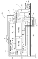
- a charging / discharging system S1 shown in FIG. 1 includes a solar power generation system (natural energy power generation system) 10, first and second distribution boards (indoor distribution boards) 20, 30, and a power measurement device (measurement device) 60. And an information collecting apparatus 100 and a stationary electric vehicle power conditioner 120 provided outdoors.
- This solar power generation system 10 is a system that is arranged in a building H such as a detached house and supplies generated power to a load (home appliance load).
- This building H is connected to a system power network (system power source) E as a power network for receiving power supply from the system power.
- system power network system power source
- the grid power grid E and the electric wire 20a wired to the building H are connected via the first and second electric energy meters M1 and M2, and the electric wire 20a is connected to the main trunk (not shown) of the first distribution board 20.
- the main trunk of the first distribution board 20 is connected to the main trunk (not shown) of the second distribution board 30.
- the first power meter M1 measures the amount of power flowing from the system power source E to the building H
- the second power meter M2 measures the amount of power flowing from the building H to the system power source E. That is, the first power meter M1 integrates the purchased power amount, and the second power meter M2 integrates the sold power amount.
- a current sensor (not shown) for detecting a current flowing through the main trunk is provided.
- a power measurement device 60 is installed in the vicinity of the second distribution board 30.
- a plurality of branch trunks 31 are connected to the main trunk of the second distribution board 30, and each of the plurality of branch trunks 31 is connected to an outlet (not shown) provided in a room of the building H with a feed line (see FIG. (Not shown).
- the solar power generation system 10 includes a solar power generation device (power generation means) 11 as a distributed power generation device, and a PV power conditioner (power conditioner for power generation) 12, and the solar power generation device 11 and the PV The power conditioner 12 is provided outdoors.
- a solar power generation device power generation means
- a PV power conditioner power conditioner for power generation
- This solar power generation device 11 is a device that generates power by directly converting solar energy, which is natural energy, into electric power.
- the PV power conditioner 12 converts the DC power generated by the solar power generator 11 into AC power and outputs the AC power.
- the PV power conditioner 12 is connected to the main trunk (not shown) of the second distribution board 30 by the feeder line 18, and the AC power of the PV power conditioner 12 is connected from the trunk to the branch trunk 31 and the feeder line. It supplies to the household appliance load connected to the said electrical outlet. 13 is an emergency outlet.
- the outer wall Ha of the building H in the vicinity of the electric vehicle power conditioner 120 is provided with a waterproof grounding outlet (charging outlet) 121, and the waterproof grounding outlet 121 is connected to the second distribution board 30 by a feeder line 122. It is connected to the main manager. AC power output from the PV power conditioner 12 and AC power from the system power source E are supplied to the waterproof grounding outlet 121 through the feeder line 122.
- the electric vehicle power conditioner 120 and the first distribution board 20 are connected by power supply lines 125 and 126, and the AC power of the system power supply E is supplied to the electric vehicle power conditioner 120 through the power supply line 125. It is like that.
- the electric vehicle power conditioner 120 and the waterproof grounding outlet 121 are arranged so as to face the parking space U.
- the electric vehicle power conditioner 120 converts AC power of the system power supply E into a predetermined DC voltage and supplies it to the electric vehicle C in the charging mode, and outputs it from the storage battery Ba of the electric vehicle C in the discharging mode.
- the direct current voltage is converted into a predetermined alternating current voltage and supplied to the first distribution board 20 via the feeder 126.
- the power conditioner 120 for electric vehicles and the main part of the 2nd distribution board 30 are connected with the feeder 127, and the alternating current power from the PV power conditioner 12 is supplied to the power conditioner 120 for electric vehicles. It has become.
- the remote control 102 is for setting the charging mode and discharging mode of the power conditioner 120 for electric vehicles.
- the information collection device 100 displays the current power generated by the solar power generation system 10 based on the transmitted measurement data, the accumulated power amount, and the like on a display device (not shown).
- the information collecting apparatus 100 is connected to an external communication network such as the Internet via the router 101, and can transmit and receive data such as measurement values to and from an external server (not shown). It can be done. [Operation]
- the power conditioner 120 for the electric vehicle and the electric vehicle C are connected by the power supply cord 130 as shown in FIG.
- the electric vehicle power conditioner 120 is set to the charging mode.
- the charging mode is set by operating the remote control 102 or a mode switch (not shown) provided in the electric vehicle power conditioner 120.
- the electric vehicle power conditioner 120 converts the AC voltage of the system power supply E input via the power supply line 125 into a predetermined DC voltage and inputs it to the electric vehicle C. Thereby, the storage battery Ba of the electric vehicle C is charged.
- the remote control 102 When charging the storage battery of the electric vehicle C with the AC power output from the PV power conditioner 12, the remote control 102 is operated to set the PV power conditioner mode. By setting this mode, the AC power output from the PV power conditioner 12 is supplied to the power conditioner 120 for the electric vehicle via the second distribution board 30 and the feeder 127, and the electric vehicle C is processed in the same manner as described above. The storage battery will be charged.
- the accumulator of the electric vehicle C is not charged with the AC power of the system power supply E.
- This is performed by switching a selector switch (not shown) built in the power conditioner 120 for an electric vehicle.
- the electric vehicle power conditioner 120 converts an AC voltage supplied from the power supply line 127 into a DC voltage
- the AC power supplied from the power supply line 125 is converted. This is done by converting the voltage to a DC voltage.
- the power conditioner 120 for the electric vehicle converts the DC voltage of the storage battery of the electric vehicle C into an AC voltage, that is, converts the DC power output from the storage battery into AC power and supplies the power line.
- the first distribution board 20 is supplied via 126.
- AC power supplied to the first distribution board 20 is supplied to the home appliance load via the second distribution board 30 and the plurality of branch trunks 31.
- the waterproof grounding outlet 121 and the electric vehicle C are connected by the power supply cord 130 as shown in FIG. Thereby, the AC power of the system power supply E or the AC power output from the PV power conditioner 12 is input to the power storage power conditioner (not shown) of the electric vehicle C.
- This storage power conditioner converts the AC voltage of AC power into a predetermined DC voltage and charges the storage battery Ba.
- the battery Ba of the electric vehicle C is charged by connecting the waterproof grounding outlet 121 and the electric vehicle C with the power supply cord 130. can do.
- the system power supply E The two electric vehicles C1 and C2 can be charged at the same time by the AC power and the AC power output from the PV power conditioner 12.
- the electric vehicle power conditioner 120 converts the DC voltage output from the storage battery Ba1 of the electric vehicle C1 into a predetermined AC voltage, and the AC power. Is supplied to the first distribution board 20, and this AC power is further supplied to the electric vehicle C2 via the second distribution board 30, the power supply line 122, the waterproof grounding outlet 121 and the power supply cord 130, whereby the electric vehicle C2 is supplied.
- the storage battery Ba2 can be charged.
- the storage battery Ba2 of the electric vehicle C2 can be charged from the storage battery Ba1 of the electric vehicle C1, and the electric vehicle C2 can be charged by the AC power of the system power supply E or the AC power of the PV power conditioner 12, for example, during a power outage at night. Even when the storage battery Ba2 cannot be charged, the storage battery Ba1 of the electric vehicle C1 can be charged from the storage battery Ba1 of the electric vehicle C1.
- the travel distance of the electric vehicle C2 can be made sufficient by charging the storage battery Ba1 of the electric vehicle C1 to the storage battery Ba2 of the electric vehicle C2. it can. That is, when a plurality of electric vehicles do not have sufficient travel distance, for example, one electric vehicle with good power consumption can be charged from storage batteries of other plurality of electric vehicles to make the travel distance sufficient.
- the amount of electricity stored in the storage battery of the electric vehicle C2 having a low power consumption can be changed from the storage battery of the electric vehicle C1 to the storage battery of the electric vehicle C2 having a high power consumption.
- the electric vehicle C2 can be charged with an amount of electricity corresponding to, for example, a traveling distance of 10 km as required.
- a charge / discharge system S1 is configured by retrofitting a first distribution board 20, an electric vehicle power conditioner 120, and a waterproof grounding outlet 121 to a building H provided with a photovoltaic power generation system 10. It is. And since the 1st distribution board 20 and the power conditioner 120 for electric vehicles were only connected with the feeder wires 125 and 126, it can attach easily after that.
- the first distribution board 20 and the electric vehicle power conditioner 120 are connected by the power supply lines 125 and 126, and the second distribution board 30 and the PV power conditioner 12 are connected by the power supply line 18. Since the second distribution board 30 and the electric vehicle power conditioner 120 are connected by the feeder line 127, the electric vehicle power conditioner 12 is installed in the building H having the existing solar power generation system 10.
- the first distribution board 20 is attached as shown in FIG. 1, and the first distribution board 20 and the electric vehicle power conditioner 120 are connected to the feeder lines 125, 126. Since the second distribution board 30 and the electric vehicle power conditioner 120 are simply connected by the feeder line 127, the charge / discharge system S1 can be easily constructed. Kill. Moreover, since the existing second distribution board 30 can be used, the charge / discharge system S1 is inexpensive.
- FIG. 4 shows the configuration of the charge / discharge system S2 of the second embodiment.
- This charging / discharging system S2 is obtained by providing a photovoltaic power generation system 15 to the charging / discharging system S1.
- This solar power generation system 15 includes a solar power generation device 16 and a PV power conditioner (power conditioner for power generation) 17, and the AC power output from the PV power conditioner 17 is the first distribution board. It is supplied to 20 main lines.
- the AC power output from the PV power conditioner 17 can be supplied only to the power conditioner 120 for an electric vehicle by switching a changeover switch (not shown). Others are the same as in the first embodiment, and a description thereof will be omitted.
- the first distribution board 20 and the second distribution board 30 are divided. However, one distribution board may be used, and the first distribution board 20 and the second distribution board may be used.
- the panel 30 is an indoor distribution board, but may be an outdoor distribution board.
- the electric vehicle power conditioner 120 and the waterproof grounding outlet 121 are provided outdoors, they may be provided indoors.
Landscapes
- Engineering & Computer Science (AREA)
- Power Engineering (AREA)
- Life Sciences & Earth Sciences (AREA)
- Sustainable Development (AREA)
- Sustainable Energy (AREA)
- Transportation (AREA)
- Mechanical Engineering (AREA)
- Charge And Discharge Circuits For Batteries Or The Like (AREA)
- Electric Propulsion And Braking For Vehicles (AREA)
- Distribution Board (AREA)
Abstract
系統電源(E)に接続された第1,第2分電盤(20),(30)から供給される交流電力を電気自動車(C)の蓄電池(Ba)へ供給したりこの蓄電池(Ba)から出力される直流電圧を交流電力に変換して第1分電盤(20)へ供給したりする電気自動車用パワーコンディショナ(120)を備えた充放電システム(S1)であって、第2分電盤(30)から交流電力が供給される防水接地コンセント(121)を設け、この防水接地コンセント(121)によって電気自動車(C)の蓄電池(Ba)を充電可能にする。
Description
この発明は、家庭用の商用電源によって電気自動車の蓄電池に充電を行ったり、この蓄電池から家電負荷へ電力を供給したりする充放電システムとこの充放電システムを備えた建物に関する。
従来から、電気自動車の蓄電池から家電負荷に電力を供給したり、家庭用の商用電源から電気自動車の蓄電池を充電したりする充放電システムが知られている(特許文献1参照)。
係る充放電システムは、商用電源から電気自動車の蓄電池を充電する場合、住宅用設備として設けた電気自動車用パワーコンディショナによって交流電圧を所定の直流電圧に変換して充電を行う。逆に、電気自動車の蓄電池から家電負荷に電力を供給する場合、上記電気自動車用パワーコンディショナによって電気自動車の蓄電池から出力される直流電力を交流電力に変換して家電負荷に供給するようになっている。
ところで、このような充放電システムにあっては、電気自動車用パワーコンディショナを例えばメンテナンスしている場合、電気自動車の蓄電池に充電することができなくなってしまうという問題がある。
この発明の目的は、電気自動車用パワーコンディショナをメンテナンスしている場合であっても電気自動車の蓄電池を充電することのできる充放電システムとこの充放電システムを備えた建物を提供することにある。
請求項1の発明は、系統電源に接続されるとともに家電負荷が接続される分電盤から供給される交流電力を電気自動車の蓄電池へ供給したり、この蓄電池から出力される直流電力を交流電力に変換して前記分電盤へ供給したりする電気自動車用パワーコンディショナを備えた充放電システムであって、
前記分電盤から交流電力が供給される充電専用コンセントを設け、この充電専用コンセントによって電気自動車の蓄電池を充電可能にしたことを特徴とする。
この発明によれば、電気自動車用パワーコンディショナをメンテナンスしている場合であっても電気自動車の蓄電池を充電することができる。
以下、この発明に係る充放電システムの実施の形態である実施例を図面に基づいて説明する。
[第1実施例]
図1に示す充放電システムS1は、太陽光発電システム(自然エネルギー発電システム)10と、第1,第2分電盤(屋内分電盤)20,30と、電力測定装置(測定装置)60と、情報収集装置100と、屋外に設けられた定置型の電気自動車用パワーコンディショナ120等とを備えている。
この太陽光発電システム10は、戸建て住宅などの建物Hに配置されて、発電した電力を負荷(家電負荷)に供給したりするシステムである。
まず、この建物Hについて説明する。この建物Hは、系統電力から電力の供給を受けるための電力網としての系統電力網(系統電源)Eに接続されている。
この系統電力網Eと建物Hに配線された電線20aとが第1,第2電力量メータM1,M2を介して繋がっており、電線20aは第1分電盤20の主幹(図示せず)に繋がっており、第1分電盤20の主幹は第2分電盤30の主幹(図示せず)に繋がっている。
第1電力量メータM1は、系統電源Eから建物Hへ流れる電力量を計測し、第2電力量メータM2は、建物Hから系統電源Eへ流れる電力量を計測する。すなわち、第1電力量メータM1は買電した電力量を積算し、第2電力量メータM2は売電した電力量を積算していく。
第2分電盤30内には、主幹に流れる電流を検出する電流センサ(図示せず)が設けられている。この第2分電盤30の近傍には電力測定装置60が設置されている。
また、第2分電盤30の主幹には、複数の分岐幹31が繋がっており、この複数の各分岐幹31には建物Hの部屋に設けたコンセント(図示せず)に給電線(図示せず)を介して繋がっている。
太陽光発電システム10は、分散型の発電装置としての太陽光発電装置(発電手段)11と、PVパワーコンディショナ(発電用パワーコンディショナ)12とを備えており、太陽光発電装置11及びPVパワーコンディショナ12は屋外に設けられている。
この太陽光発電装置11は、自然エネルギーである太陽光エネルギーを直接電力に変換して発電を行う装置である。
PVパワーコンディショナ12は、太陽光発電装置11が発電した直流電力を交流電力に変換して出力するものである。
また、PVパワーコンディショナ12は、給電線18によって第2分電盤30の主幹(図示せず)に繋がっており、PVパワーコンディショナ12の交流電力をその主幹から分岐幹31及び給電線を介して上記コンセントに接続された家電負荷に供給するようになっている。13は非常用コンセントである。
電気自動車用パワーコンディショナ120の近傍の建物Hの外壁面Haには、防水接地コンセント(充電専用コンセント)121が設けられており、この防水接地コンセント121は給電線122により第2分電盤30の主幹に繋がっている。この給電線122によりPVパワーコンディショナ12から出力される交流電力や系統電源Eの交流電力が防水接地コンセント121へ供給されるようになっている。
電気自動車用パワーコンディショナ120と第1分電盤20とは給電線125,126で繋がっており、系統電源Eの交流電力が給電線125を介して電気自動車用パワーコンディショナ120へ供給されるようになっている。
また、電気自動車用パワーコンディショナ120及び防水接地コンセント121は駐車スペースUを臨むように配置されている。
電気自動車用パワーコンディショナ120は、充電モードのとき系統電源Eの交流電力を所定の直流電圧に変換して電気自動車Cへ供給するものであり、放電モードのとき電気自動車Cの蓄電池Baから出力される直流電圧を所定の交流電圧に変換して給電線126を介して第1分電盤20へ供給するようになっている。また、電気自動車用パワーコンディショナ120と第2分電盤30の主幹とが給電線127で繋がっており、PVパワーコンディショナ12からの交流電力が電気自動車用パワーコンディショナ120へ供給されるようになっている。
リモートコントロール102は、電気自動車用パワーコンディショナ120の充電モードや放電モードを設定したりするものである。
情報収集装置100は、送信されてきた測定データに基づいて太陽光発電システム10が発電している現時点の電力や積算した電力量などを図示しない表示装置に表示したりする。
また、情報収集装置100は、ルータ101を介してインターネットなどの外部の通信網に繋がっており、外部のサーバ(図示せず)との間で、計測値などのデータの送受信などを行うことができるようになっている。
[動 作]
[動 作]
次に、上記のように構成される充放電システムS1の動作について簡単に説明する。
電気自動車Cの蓄電池(図示せず)を充電する場合、先ず、電気自動車用パワーコンディショナ120と電気自動車Cとを図1に示すように給電コード130で接続する。次に、電気自動車用パワーコンディショナ120を充電モードに設定する。この充電モードの設定は、リモートコントロール102の操作または電気自動車用パワーコンディショナ120に設けられている図示しないモードスイッチの操作によって行う。
電気自動車用パワーコンディショナ120は、充電モードが設定されると、給電線125を介して入力される系統電源Eの交流電圧を所定の直流電圧に変換して電気自動車Cへ入力させる。これにより、電気自動車Cの蓄電池Baは充電されていく。
PVパワーコンディショナ12から出力される交流電力で電気自動車Cの蓄電池を充電する場合には、リモートコントロール102を操作してPVパワーコンディショナモードを設定する。このモードの設定により、PVパワーコンディショナ12から出力される交流電力が第2分電盤30及び給電線127を介して電気自動車用パワーコンディショナ120へ供給されて上記と同様にして電気自動車Cの蓄電池が充電されていく。
この場合、系統電源Eの交流電力では電気自動車Cの蓄電池は充電されないようになっている。これは、電気自動車用パワーコンディショナ120に内蔵されている図示しない切換スイッチの切り換えによって行う。例えば、PVパワーコンディショナモードのとき、電気自動車用パワーコンディショナ120は給電線127から供給されてくる交流電圧を直流電圧に変換し、系統電源モードのとき、給電線125から供給されてくる交流電圧を直流電圧に変換することによって行う。
放電モードが設定された場合、電気自動車用パワーコンディショナ120は、電気自動車Cの蓄電池の直流電圧を交流電圧に変換して、すなわち蓄電池から出力される直流電力を交流電力に変換して給電線126を介して第1分電盤20へ供給する。
第1分電盤20に供給された交流電力は第2分電盤30及び複数の分岐幹31を介して家電負荷に供給される。
電気自動車用パワーコンディショナ120がメンテナンスなどにより使用できない場合、図2に示すように、防水接地コンセント121と電気自動車Cとを給電コード130で接続する。これにより、系統電源Eの交流電力またはPVパワーコンディショナ12から出力される交流電力が電気自動車Cの蓄電パワーコンディショナ(図示せず)へ入力することになる。この蓄電パワーコンディショナは交流電力の交流電圧を所定の直流電圧に変換して蓄電池Baを充電していく。
このように、電気自動車用パワーコンディショナ120がメンテナンスなどにより使用できない場合であっても、防水接地コンセント121と電気自動車Cとを給電コード130で接続することにより、電気自動車Cの蓄電池Baを充電することができる。
また、図3に示すように、電気自動車用パワーコンディショナ120と電気自動車C1とを給電コード130で接続し、防水接地コンセント121と電気自動車C2とを給電コード130で接続すれば、系統電源Eの交流電力やPVパワーコンディショナ12から出力される交流電力によって、二台の電気自動車C1,C2を同時に充電することができる。
図3に示すように電気自動車C1,C2を接続した状態で、電気自動車用パワーコンディショナ120によって、電気自動車C1の蓄電池Ba1から出力される直流電圧を所定の交流電圧に変換してその交流電力を第1分電盤20に供給し、さらにこの交流電力を第2分電盤30、給電線122、防水接地コンセント121及び給電コード130を介して電気自動車C2へ供給することにより、電気自動車C2の蓄電池Ba2を充電することができる。
このように、電気自動車C1の蓄電池Ba1から電気自動車C2の蓄電池Ba2を充電することができ、例えば夜間の停電時、系統電源Eの交流電力やPVパワーコンディショナ12の交流電力によって電気自動車C2の蓄電池Ba2を充電することができない場合であっても、電気自動車C1の蓄電池Ba1から電気自動車C2の蓄電池Ba2へ充電することができる。
例えば、電気自動車C1,C2の両方とも走行距離が十分でない場合、電気自動車C1の蓄電池Ba1から電気自動車C2の蓄電池Ba2へ充電することにより、電気自動車C2の走行距離を十分なものにすることができる。すなわち、複数の電気自動車が走行距離が十分でない場合、例えば電費のよい1台の電気自動車に他の複数の電気自動車の蓄電池から充電させて走行距離を十分なものにすることができる。
また、電費の悪い例えば電気自動車C1の蓄電池から電費の良い電気自動車C2の蓄電池へ蓄えられた電気量を入れ替えることができる。
また、多人数が乗れるが電費の悪い電気自動車と、少人数しか乗れないが電費の良い電気自動車とから、そのときの必要に応じた電気自動車を選択し、その電気自動車に電力を集中させて使用することができる。
また、必要に応じて例えば走行距離10km分だけの電気量を電気自動車C2に充電させることもできる。
第1実施例では、太陽光発電システム10を設けた建物Hに第1分電盤20と電気自動車用パワーコンディショナ120と防水接地コンセント121とを後付けして、充放電システムS1を構成したものである。そして、第1分電盤20と電気自動車用パワーコンディショナ120とを給電線125,126で繋いだだけなので、その後付けは簡単に行える。
この充放電システムS1は、第1分電盤20と電気自動車用パワーコンディショナ120とを給電線125,126で繋げ、第2分電盤30とPVパワーコンディショナ12とを給電線18で繋げ、第2分電盤30と電気自動車用パワーコンディショナ120とを給電線127で繋げて構成したものであるから、既存の太陽光発電システム10を備えた建物Hに電気自動車用パワーコンディショナ12を後付けして充放電システムS1を構築する場合、第1分電盤20を図1に示すように取り付け、この第1分電盤20と電気自動車用パワーコンディショナ120とを給電線125,126で繋げ、第2分電盤30と電気自動車用パワーコンディショナ120とを給電線127で繋げるだけなので、充放電システムS1を簡単に構築することができる。しかも、既存の第2分電盤30を利用することができるので、充放電システムS1は安価なものとなる。
[第2実施例]
[第2実施例]
図4は第2実施例の充放電システムS2の構成を示す。この充放電システムS2は、充放電システムS1に太陽光発電システム15を設けたものである。この太陽光発電システム15は、太陽光発電装置16と、PVパワーコンディショナ(発電用パワーコンディショナ)17とを備えており、PVパワーコンディショナ17から出力される交流電力が第1分電盤20の主幹線に供給されるようになっている。
また、PVパワーコンディショナ17から出力される交流電力は、図示しない切換スイッチの切り換えによって電気自動車用パワーコンディショナ120のみに供給することができるようになっている。他は、第1実施例と同様なのでその説明は省略する。
上記実施例はいずれも第1分電盤20と第2分電盤30とに分けているが、1つの分電盤であってもよく、また、第1分電盤20及び第2分電盤30は屋内分電盤であるが、屋外分電盤であってもよい。
上記実施例はいずれも太陽光発電システムを備えているが必ずしも備えている必要はない。
また、電気自動車用パワーコンディショナ120や防水接地コンセント121を屋外に設けているが、屋内に設けてもよい。
この発明は、上記実施例に限られるものではなく、請求の範囲の発明の要旨を逸脱しない限り、設計の変更や追加等は許容される。
本出願は、2014年4月17日に日本国特許庁に出願された特願2014-085358に基づいて優先権を主張し、その全ての開示は完全に本明細書で参照により組み込まれる。
Claims (8)
- 系統電源に接続されるとともに家電負荷が接続される分電盤から供給される交流電力を電気自動車の蓄電池へ供給したり、この蓄電池から出力される直流電力を交流電力に変換して前記分電盤へ供給したりする電気自動車用パワーコンディショナを備えた充放電システムであって、
前記分電盤から交流電力が供給される充電専用コンセントを設け、この充電専用コンセントによって電気自動車の蓄電池を充電可能にしたことを特徴とする充放電システム。 - 前記充電専用コンセント及び電気自動車用パワーコンディショナを屋外に設けるとともに、該充電専用コンセント及び電気自動車用パワーコンディショナを駐車スペースを臨む位置に配置したことを特徴とする請求項1に記載の充放電システム。
- 自然エネルギによって発電する発電手段と、この発電手段から出力される直流電力を交流電力に変換して前記分電盤へ出力する発電用パワーコンディショナとを備え、
前記充電専用コンセントには、前記発電用パワーコンディショナから出力される交流電力が供給可能となっていることを特徴とする請求項1または請求項2に記載の充放電システム。 - 前記電気自動車用パワーコンディショナには、前記発電用パワーコンディショナから出力される交流電力が供給可能となっていることを特徴とする請求項3に記載の充放電システム。
- 前記電気自動車用パワーコンディショナに接続される電気自動車の蓄電池を放電させることによって、前記充電専用コンセントに接続される他の電気自動車の蓄電池を充電可能にしたことを特徴とする請求項1ないし請求項4のいずれか1項に記載の充放電システム。
- 前記分電盤は、第1分電盤と第2分電盤とで構成され、
前記第1分電盤は、前記系統電源Eに接続されるとともに前記電気自動車用パワーコンディショナに接続され、
前記第2分電盤は、前記家電負荷及び充電専用コンセントが接続され且つ前記発電用パワーコンディショナから出力される交流電力が供給されることを特徴とする請求項3に記載の充放電システム。 - 前記第2分電盤に前記電気自動車用パワーコンディショナが接続され、前記発電用パワーコンディショナから出力される交流電力が前記電気自動車用パワーコンディショナに供給可能となっていることを特徴とする請求項6に記載の充放電システム。
- 請求項1ないし請求項7のいずれか1項に記載の充放電システムを備えたことを特徴とする建物。
Applications Claiming Priority (3)
| Application Number | Priority Date | Filing Date | Title |
|---|---|---|---|
| JP2014-085358 | 2014-04-17 | ||
| JP2014085358A JP5668161B1 (ja) | 2014-04-17 | 2014-04-17 | 充放電システムと建物 |
| JP2014251590A JP6243832B2 (ja) | 2014-04-17 | 2014-12-12 | 充放電システムと建物 |
Publications (1)
| Publication Number | Publication Date |
|---|---|
| WO2015159735A1 true WO2015159735A1 (ja) | 2015-10-22 |
Family
ID=59313369
Family Applications (1)
| Application Number | Title | Priority Date | Filing Date |
|---|---|---|---|
| PCT/JP2015/060595 Ceased WO2015159735A1 (ja) | 2014-04-17 | 2015-04-03 | 充放電システムと建物 |
Country Status (2)
| Country | Link |
|---|---|
| JP (2) | JP5668161B1 (ja) |
| WO (1) | WO2015159735A1 (ja) |
Families Citing this family (4)
| Publication number | Priority date | Publication date | Assignee | Title |
|---|---|---|---|---|
| JP6427044B2 (ja) * | 2015-03-11 | 2018-11-21 | 積水化学工業株式会社 | 充放電システム |
| JP6386401B2 (ja) * | 2015-03-18 | 2018-09-05 | 積水化学工業株式会社 | 充放電システム |
| JP6423746B2 (ja) * | 2015-03-20 | 2018-11-14 | 積水化学工業株式会社 | 充放電システム |
| JP2017127137A (ja) * | 2016-01-14 | 2017-07-20 | 三菱電機株式会社 | 開閉器箱および電力供給システム |
Citations (3)
| Publication number | Priority date | Publication date | Assignee | Title |
|---|---|---|---|---|
| JP2012228034A (ja) * | 2011-04-18 | 2012-11-15 | Mitsubishi Electric Corp | 電気自動車と家屋間の充放電システム |
| JP2013081289A (ja) * | 2011-10-03 | 2013-05-02 | Panasonic Corp | 電力制御装置 |
| JP2014068451A (ja) * | 2012-09-25 | 2014-04-17 | Daiwa House Industry Co Ltd | 電力供給システム |
Family Cites Families (5)
| Publication number | Priority date | Publication date | Assignee | Title |
|---|---|---|---|---|
| JPH09107605A (ja) * | 1995-10-11 | 1997-04-22 | Sumitomo Wiring Syst Ltd | 電気自動車用充電システム |
| JP5368915B2 (ja) * | 2009-09-09 | 2013-12-18 | 中国電力株式会社 | 継電器、及び、電力供給システム |
| JP5461445B2 (ja) * | 2011-01-07 | 2014-04-02 | 中国電力株式会社 | 電力利用システム |
| JP2013034326A (ja) * | 2011-08-02 | 2013-02-14 | Toyota Industries Corp | 車両用充電システムおよび車両用充電ケーブル |
| JP5967516B2 (ja) * | 2011-11-22 | 2016-08-10 | パナソニックIpマネジメント株式会社 | 電力管理装置、電力管理プログラム、及び、電力分配システム |
-
2014
- 2014-04-17 JP JP2014085358A patent/JP5668161B1/ja active Active
- 2014-12-12 JP JP2014251590A patent/JP6243832B2/ja active Active
-
2015
- 2015-04-03 WO PCT/JP2015/060595 patent/WO2015159735A1/ja not_active Ceased
Patent Citations (3)
| Publication number | Priority date | Publication date | Assignee | Title |
|---|---|---|---|---|
| JP2012228034A (ja) * | 2011-04-18 | 2012-11-15 | Mitsubishi Electric Corp | 電気自動車と家屋間の充放電システム |
| JP2013081289A (ja) * | 2011-10-03 | 2013-05-02 | Panasonic Corp | 電力制御装置 |
| JP2014068451A (ja) * | 2012-09-25 | 2014-04-17 | Daiwa House Industry Co Ltd | 電力供給システム |
Also Published As
| Publication number | Publication date |
|---|---|
| JP2015208059A (ja) | 2015-11-19 |
| JP5668161B1 (ja) | 2015-02-12 |
| JP6243832B2 (ja) | 2017-12-06 |
| JP2015208209A (ja) | 2015-11-19 |
Similar Documents
| Publication | Publication Date | Title |
|---|---|---|
| JP5153959B1 (ja) | エネルギマネジメントシステム | |
| JP5990786B2 (ja) | 充放電システム | |
| JP6460257B2 (ja) | 蓄電装置、蓄電装置組立体、電気・電子機器、電動移動手段及び電力システム、並びに、蓄電装置組立体の組み立て方法 | |
| WO2018029937A1 (ja) | 電力供給装置 | |
| JP6243832B2 (ja) | 充放電システムと建物 | |
| JP6118691B2 (ja) | エネルギマネジメントシステム | |
| EP3811486A1 (en) | System for the control of electric energy | |
| JP5433105B1 (ja) | エネルギマネジメントシステム | |
| US10389134B2 (en) | Electrical power distribution system and method | |
| JP6243617B2 (ja) | 電力システム | |
| JP6182032B2 (ja) | エネルギマネジメントシステム | |
| JP7012279B2 (ja) | 配電システム及び設置方法 | |
| JP4722585B2 (ja) | 電力料金だけでなくco2排出量をも削減することができる、太陽電池及び/又はキュービクルを使用した集合住宅用電力削減システム | |
| JP2016116253A (ja) | 充放電システム | |
| JP2016046829A (ja) | 電力供給システム | |
| JP6081329B2 (ja) | エネルギマネジメントシステム | |
| JP3223017U (ja) | 太陽光発電用蓄放電装置 | |
| JP6313197B2 (ja) | 充放電システム | |
| JP6181912B2 (ja) | 建物の改修方法 | |
| JP7320795B2 (ja) | 配電システム及び設置方法 | |
| JP6313144B2 (ja) | 充放電システム | |
| JP5364199B1 (ja) | エネルギマネジメントシステム | |
| JP2018137863A (ja) | 蓄電池地域共用システム | |
| JP2014192985A (ja) | 電力システム | |
| JP6423746B2 (ja) | 充放電システム |
Legal Events
| Date | Code | Title | Description |
|---|---|---|---|
| 121 | Ep: the epo has been informed by wipo that ep was designated in this application |
Ref document number: 15779715 Country of ref document: EP Kind code of ref document: A1 |
|
| NENP | Non-entry into the national phase |
Ref country code: DE |
|
| 122 | Ep: pct application non-entry in european phase |
Ref document number: 15779715 Country of ref document: EP Kind code of ref document: A1 |