WO2015159393A1 - アイドラ及び履帯式走行装置 - Google Patents
アイドラ及び履帯式走行装置 Download PDFInfo
- Publication number
- WO2015159393A1 WO2015159393A1 PCT/JP2014/060851 JP2014060851W WO2015159393A1 WO 2015159393 A1 WO2015159393 A1 WO 2015159393A1 JP 2014060851 W JP2014060851 W JP 2014060851W WO 2015159393 A1 WO2015159393 A1 WO 2015159393A1
- Authority
- WO
- WIPO (PCT)
- Prior art keywords
- idler
- wear plate
- contact surface
- crawler belt
- fixing member
- Prior art date
- Legal status (The legal status is an assumption and is not a legal conclusion. Google has not performed a legal analysis and makes no representation as to the accuracy of the status listed.)
- Ceased
Links
Images





Classifications
-
- B—PERFORMING OPERATIONS; TRANSPORTING
- B62—LAND VEHICLES FOR TRAVELLING OTHERWISE THAN ON RAILS
- B62D—MOTOR VEHICLES; TRAILERS
- B62D55/00—Endless track vehicles
- B62D55/08—Endless track units; Parts thereof
- B62D55/14—Arrangement, location, or adaptation of rollers
- B62D55/145—Rollers with replaceable wear rings or rims
-
- B—PERFORMING OPERATIONS; TRANSPORTING
- B60—VEHICLES IN GENERAL
- B60Y—INDEXING SCHEME RELATING TO ASPECTS CROSS-CUTTING VEHICLE TECHNOLOGY
- B60Y2200/00—Type of vehicle
- B60Y2200/20—Off-Road Vehicles
- B60Y2200/25—Track vehicles
-
- B—PERFORMING OPERATIONS; TRANSPORTING
- B60—VEHICLES IN GENERAL
- B60Y—INDEXING SCHEME RELATING TO ASPECTS CROSS-CUTTING VEHICLE TECHNOLOGY
- B60Y2200/00—Type of vehicle
- B60Y2200/40—Special vehicles
- B60Y2200/41—Construction vehicles, e.g. graders, excavators
- B60Y2200/411—Bulldozers, Graders
-
- B—PERFORMING OPERATIONS; TRANSPORTING
- B62—LAND VEHICLES FOR TRAVELLING OTHERWISE THAN ON RAILS
- B62D—MOTOR VEHICLES; TRAILERS
- B62D55/00—Endless track vehicles
- B62D55/08—Endless track units; Parts thereof
- B62D55/18—Tracks
- B62D55/20—Tracks of articulated type, e.g. chains
Definitions
- the present invention relates to an idler and a crawler type traveling device.
- a crawler type traveling device having a crawler belt wound around an idler and a drive wheel has been widely used for work machines such as bulldozers.
- a technique has been proposed in which a disk-shaped idler body is surrounded by a plurality of arc-shaped wear plates (see Patent Document 1).
- the wear plate is fixed to the idler body by a fixing member disposed on the wear plate.
- the wear plate has a crawler belt contact surface provided on both sides of the fixing member, and the fixing member functions as a guide portion for guiding the crawler belt so that the crawler belt is held at a position in contact with the crawler belt contact surface.
- the present invention has been made in view of the above-described situation, and an object thereof is to provide an idler and a crawler type traveling device capable of suppressing breakage of a fastener for fixing a wear plate.
- the idler according to the first aspect is an idler around which a crawler belt is wound.
- the idler includes a disk-shaped idler body having a rotation center axis, and a plurality of wear plate assemblies arranged so as to surround the peripheral surface of the idler body.
- Each of the plurality of wear plate assemblies includes an arcuate wear plate disposed on the peripheral surface of the idler body, a first fixing member for fixing the wear plate to the idler body, and a first fixing member fastened to the idler body.
- a first fastener for carrying out.
- the wear plate is a track contact surface that contacts the track, a guide portion that projects from the track contact surface, guides the track on the track contact surface, contacts the idler body, and is perpendicular to the axial direction of the center axis of rotation.
- the first contact surface is opposed to the second contact surface in the axial direction.
- the wear plate is pivoted when an axial force is applied from the crawler belt to the guide portion. Shifting in the direction can be suppressed. Moreover, since a force is not applied to a 1st fastener via a 1st fixing member, it can suppress that a 1st fastener is damaged.
- the idler according to the second aspect relates to the first aspect, and the wear plate has an opening.
- the idler body is formed on the peripheral surface and has a convex portion arranged in the opening.
- Each of the first contact surface and the second contact surface is a part of the inner surface of the opening, and contacts the convex portion.
- the wear plate can be reduced in size and weight as compared with a case where a part of the wear plate is extended on both side surfaces of the idler body and brought into contact with the idler body.
- the idler according to the third aspect relates to the second aspect, and the guide portion is provided at the periphery of the opening.
- the guide portion can be effectively used as the opening for providing the first contact surface and the second contact surface, the opening is formed separately from the guide portion. Compared to the above, the wear plate can be reduced in size and weight.
- the idler according to the fourth aspect relates to the second aspect, and the first fixing member is disposed in the opening.
- gravel entering between the crawler belt and the idler can be prevented from coming into contact with the first fixing member.
- the idler according to the fifth aspect relates to the first aspect, and the idler main body has an outer surface continuous to the peripheral surface and an inner surface connected to the peripheral surface and provided on the opposite side of the outer surface.
- the wear plate has a first extending portion extending on the outer surface and a second extending portion extending on the inner surface. The first contact surface is in contact with the outer surface, and the second contact surface is in contact with the inner surface.
- the displacement of the wear plate can be more effectively suppressed.
- the idler according to a sixth aspect relates to the first aspect, and each of the plurality of wear plate assemblies fastens the second fixing member for fixing the wear plate to the idler body and the second fixing member to the idler body. And a second fastener.
- the first fixing member is separated from the second fixing member in the circumferential direction around the rotation center axis.
- the wear plate can be fixed by the first fixing member and the second fixing member, when the wear plate is pressed down by the crawler belt, a part of the wear plate is lifted from the idler body. Can be suppressed.
- the idler according to the seventh aspect relates to the sixth aspect, and the guide portion of the wear plate has an opening extending in the circumferential direction.
- the first fixing member and the second fixing member are disposed in the opening.
- the wear plate can be further reduced in weight by increasing the size of the opening.
- An idler relates to any one of the first to seventh aspects, and the wear plate includes a first locking portion locked between the first fixing member and the idler body, and the first engagement.
- a first buffer member disposed between the stopper and the first fixing member;
- rattling of the wear plate relative to the idler body can be suppressed.
- the idler according to the ninth aspect relates to any one of the first to eighth aspects, and the plurality of wear plate assemblies include a first wear plate and a second wear plate adjacent to each other.
- Each of the first wear plate and the second wear plate includes a first crawler belt contact surface and a second crawler belt contact surface.
- the first wear plate has a first end that defines the end of the first crawler belt contact surface on the second wear plate side and a second end of the second crawler belt contact surface that defines the end of the second crawler track contact surface on the second wear plate side in plan view. And end.
- the first end portion is inclined with respect to the axial direction.
- the idler according to the ninth aspect it is possible to suppress the crawler belt and the first crawler belt contact surface from being in line contact as compared with the case where the first end portion is parallel to the axial direction. Therefore, since the load pressure applied near the first end can be reduced, local wear in the vicinity of the first end can be suppressed.
- the idler according to the tenth aspect relates to the ninth aspect, and the second end portion is inclined with respect to the axial direction.
- the crawler belt and the second crawler belt contact surface can be prevented from making line contact as compared with the case where the second end portion is parallel to the axial direction. Therefore, since the load pressure applied to the vicinity of the second end can be reduced, local wear in the vicinity of the second end can be suppressed.
- An idler according to an eleventh aspect relates to the ninth or tenth aspect, and the second wear plate includes a third end portion that defines an end of the first crawler belt contact surface on the first wear plate side in a plan view. , And a fourth end portion defining an end of the second crawler belt contact surface on the first wear plate side.
- the third end portion is inclined with respect to the axial direction.
- line contact between the crawler belt and the first crawler belt contact surface can be suppressed as compared with the case where the third end portion is parallel to the axial direction. Therefore, since the load pressure applied to the vicinity of the third end can be reduced, local wear in the vicinity of the third end can be suppressed.
- the idler according to the twelfth aspect relates to the eleventh aspect, and the fourth end portion is inclined with respect to the axial direction.
- the crawler belt and the second crawler belt contact surface can be prevented from making line contact as compared with the case where the fourth end portion is parallel to the axial direction. Therefore, since the load pressure applied to the vicinity of the fourth end can be reduced, local wear in the vicinity of the fourth end can be suppressed.
- An idler according to a thirteenth aspect relates to the twelfth aspect, wherein the first end and the third end are point-symmetric with respect to a predetermined center of symmetry in plan view, and the second end and the fourth end The end portion is point symmetric with respect to a predetermined symmetry center point in plan view.
- the productivity of the wear plate can be increased.
- a crawler type traveling apparatus is any one of the first to thirteenth, which is disposed on the opposite side of the sprocket via the track frame, the sprocket disposed in front of or behind the track frame.
- an idler and a crawler type traveling device capable of suppressing breakage of a fastener for fixing a wear plate.
- upper”, “lower”, “front”, and “rear” are terms based on an operator seated in a driver's seat of a work machine to which the crawler type traveling device is mounted. Further, “inside” and “outside” are terms based on the center line in the width direction of the work machine to which the crawler type traveling device is attached.
- FIG. 1 is a side view of a crawler belt type traveling apparatus 1 according to the embodiment.
- the crawler belt type traveling device 1 includes a track frame 10, an idler moving mechanism 20, a sprocket 30, an idler 40, a crawler belt 50, two upper rollers 60, and six lower rollers 70.
- the track frame 10 is a framework of a vehicle body of a working machine (not shown) (for example, a bulldozer or an excavator).
- the track frame 10 extends in the front-rear direction.
- the idler moving mechanism 20 is attached to the front end portion of the track frame 10.
- the idler moving mechanism 20 can move back and forth with respect to the track frame 10.
- the idler moving mechanism 20 adjusts the tension of the crawler belt 50 that varies depending on the shape of the ground by changing the position of the idler 30 with respect to the sprocket 20 while the crawler type traveling device 1 is traveling.
- the sprocket 30 is disposed behind the track frame 10.
- the sprocket 30 is rotationally driven by a hydraulic motor (not shown).
- a crawler belt 50 is wound around the sprocket 30.
- the sprocket 30 has a tooth 31 that meshes with the crawler belt 50.
- the idler 40 is disposed in front of the track frame 10.
- the idler 40 is rotatably supported by the idler moving mechanism 20.
- the idler 40 is attached to the idler moving mechanism 20 via the support shaft 40a.
- a crawler belt 50 is wound around the idler 40. The configuration of the idler 40 will be described later.
- the crawler belt 50 is wound around the sprocket 30 and the idler 40.
- the crawler belt type traveling device 1 travels as the crawler belt 50 revolves by the rotational drive of the sprocket 30.
- the crawler belt 50 includes a plurality of track links 51, a plurality of bearing portions 52, and a plurality of shoe plates 53. Two adjacent track links 51 are pivotally connected by a bearing portion 52.
- the track link 51 has a pair of left and right treads 51a.
- the pair of left and right tread surfaces 51a are in contact with first and second crawler belt contact surfaces 200a and 200b of a wear plate 200 to be described later.
- Each tread surface 51a is formed in a substantially flat planar shape.
- the bearing portion 52 includes a pin inserted through two adjacent track links 51 and a bush fitted around the pin.
- the two upper rollers 60 are arranged on the upper side of the track frame 10.
- the upper roller 60 guides the crawler belt 50 from below.
- the two upper rollers 60 are separated in the front-rear direction.
- the upper roller 60 rolls in contact with the crawler belt 50.
- the six lower rollers 70 are disposed below the track frame 10.
- the six lower rollers 70 distribute the weight of the vehicle body applied to the crawler belt 50.
- the six lower rollers 70 are separated in the front-rear direction.
- the lower roller 70 rolls in contact with the crawler belt 50.
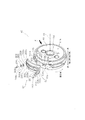
- FIG. 2 is a perspective view of the idler 40.
- FIG. 3 is a plan view of the wear plate assembly 42.
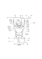
- 4 is a cross-sectional view taken along the line AA in FIG. In FIG. 2, one wear plate assembly 42 is disassembled to explain the configuration of the idler 40.
- the idler 40 includes an idler body 41 and five wear plate assemblies 42.
- the idler body 41 is formed in a disk shape having a rotation center axis AX.
- the idler body 41 includes a peripheral surface 41a, an outer surface 41b, an inner surface 41c, an insertion hole 41d, and a convex portion 41e.
- the peripheral surface 41 a is the entire side surface of the idler body 41.
- the outer surface 41b continues to the peripheral surface 41a.
- the outer surface 41b is a surface arranged outward in the width direction when the crawler type traveling device 1 is attached to the work machine.
- the inner surface 41c is continuous with the peripheral surface 41a.
- the inner surface 41c is provided on the opposite side of the outer surface 41b.
- the inner surface 41c is a surface arranged inward in the width direction when the crawler type traveling device 1 is attached to the work machine.
- the insertion hole 41 d is formed along the rotation center axis AX at the center of the idler body 41. As shown in FIG. 4, the support shaft 40a is inserted through the insertion hole 41d.
- the convex portion 41e is formed on the peripheral surface 41a.
- the convex part 41e is arrange
- the convex portion 41 e includes a support portion 100, a first boss 101, a second boss 102, a first island portion 103, a second island portion 104, and a third island portion 105.
- the support part 100 is formed so as to extend in the circumferential direction around the rotation center axis AX.
- the support part 100 is formed in an annular shape. That is, the support part 100 is continuously formed over the entire circumference of the peripheral surface 41a.
- the support portion 100 supports the wear plate 200 so that the wear plate 200 does not shift in the axial direction when a force in the axial direction (that is, the width direction) of the rotation center axis AX is applied to the wear plate 200 from the crawler belt 50.
- the support portion 100 has a first support surface 100S and a second support surface 100T.
- the first support surface 100S is provided perpendicular to the axial direction of the rotation center axis AX.
- the first support surface 100S is formed in an arc shape extending in the circumferential direction.
- the second support surface 100T is provided perpendicular to the axial direction of the rotation center axis AX.
- the second support surface 100T is formed in an arc shape extending in the circumferential direction.
- the first support surface 100S is provided on the opposite side of the second support surface 100T. Since the first support surface 100S and the second support surface 100T are in contact with the wear plate 200, they may be referred to as “contacted surfaces”.
- the first boss 101 is integrally formed on the support portion 100.
- the first boss 101 is disposed between the first island portion 103 and the second island portion 104 in the circumferential direction.
- the first boss 101 is formed in a cylindrical shape.
- a first fastener 203 (described later) is inserted through the first boss 101.
- the first fastening hole 101 a into which the first fastener 203 is inserted passes through the first boss 101 and the support portion 100 and reaches the idler body 41.
- the first fastening hole 101a is formed along a radial direction centered on the rotation center axis AX.
- the second boss 102 is integrally formed on the support portion 100.
- the second boss 102 is disposed between the first island portion 103 and the third island portion 105 in the circumferential direction.
- the second boss 102 is formed in a cylindrical shape.
- a second fastener 204 described later is inserted into the second boss 102. Similar to the first fastening hole 101a, the second fastening hole 102a into which the second fastener 204 is inserted penetrates the second boss 102 and the support portion 100 and reaches the idler body 41.
- the second fastening hole 102a is formed along the radial direction.
- Each of the first to third island portions 103 to 105 is integrally formed on the support portion 100.
- Each of the first to third island portions 103 to 105 is formed in a trapezoidal shape.
- the first island portion 103 is disposed between the first boss 101 and the second boss 102 in the circumferential direction.
- the second island 104 is arranged on the opposite side of the first island 103 via the first boss 101.
- the third island 105 is disposed on the opposite side of the first island 103 via the second boss 102.
- each of the first to third island portions 103 to 105 is not in contact with the wear plate assembly 42.
- the five wear plate assemblies 42 are arranged in order so as to surround the peripheral surface 41a of the idler body 41.
- Each of the five wear plate assemblies 42 includes a wear plate 200, a first fixing plate (first fixing member) 201, a second fixing plate (second fixing member) 202, a first fastener 203, and a second fastener.
- a fastener 204, a first buffer member 205, and a second buffer member 206 are provided.
- the wear plate 200 is an arc-shaped plate member as viewed in the width direction.
- the wear plate 200 can be made of, for example, a steel plate.
- the wear plate 200 includes a first crawler belt contact surface 200a, a second crawler belt contact surface 200b, a guide portion 200c, an opening portion 200d, and a pair of first locking portions 200e. And a pair of second locking portions 200f.
- the planar shape of the wear plate 200 will be described later.
- the first crawler belt contact surface 200a is the outer circumferential surface of the wear plate 200 in the width direction.
- the second crawler belt contact surface 200 b is a circumferential surface on the inner side in the width direction of the wear plate 200.
- Each of the first and second crawler belt contact surfaces 200a, 200b is formed in an arc shape extending in the circumferential direction.
- the first crawler belt contact surface 200a is formed on the opposite side of the second crawler belt contact surface 200b via the guide portion 200c.
- each of the first and second crawler belt contact surfaces 200 a and 200 b comes into contact with a pair of tread surfaces 51 a of the track link 51 of the crawler belt 50. Therefore, since the first and second crawler belt contact surfaces 200a and 200b are easily worn, the first and second crawler belt contact surfaces 200a and 200b are subjected to hardening techniques such as quenching, carburizing or nitriding, and PVD (physical vapor deposition). It is preferable that the curing treatment is performed by a surface treatment technique such as CVD (chemical evaporation) or ion coating. Specifically, the hardness HRC of the first and second crawler belt contact surfaces 200a and 200b is preferably 45 or more.
- the first and second crawler belt contact surfaces 200a and 200b are an example of a crawler belt contact surface that contacts the track link 51 of the crawler belt 50.
- the shape and size of the first and second crawler belt contact surfaces 200a and 200b can be changed as appropriate.
- the guide portion 200c is formed between the first and second crawler belt contact surfaces 200a and 200b.
- the guide part 200c extends in the circumferential direction.
- the guide part 200c protrudes radially outward from the first and second crawler belt contact surfaces 200a, 200b.
- the guide portion 200 c is a flange that guides the track link 51 so as to properly contact the first and second crawler belt contact surfaces 200 a and 200 b.
- the opening part 200d is formed in the guide part 200c.
- the opening 200d extends in the circumferential direction.
- a protrusion 41e of the idler body 41 is disposed in the opening 200d.
- a first fixing plate 201, a second fixing plate 202, a first fastener 203, a second fastener 204, a first buffer member 205, and a second buffer member 206 are disposed in the opening 200d.
- the opening 200d has an inner surface Sd.
- the inner side surface Sd includes a first contact surface 200S and a second contact surface 200T.
- the first contact surface 200S and the second contact surface 200T are regions of the inner surface Sd that are closest to the idler body 41 in the radial direction.
- the first contact surface 200S is provided perpendicular to the axial direction.
- the first contact surface 200S is formed in an arc shape extending in the circumferential direction.
- the second contact surface 200T is provided perpendicular to the axial direction.
- the second contact surface 200T is formed in an arc shape extending in the circumferential direction.
- the first contact surface 200S is provided so as to face the second contact surface 200T in the axial direction.
- the first contact surface 200 ⁇ / b> S contacts the first support surface 100 ⁇ / b> S of the support unit 100.
- the second contact surface 200T is in contact with the second support surface 100T of the support unit 100.
- the wear plate 200 does not come off even if an axial force is applied from the crawler belt 50 by being in contact with the idler body 41 at the first contact surface 200S and the second contact surface 200T.
- the pair of first locking portions 200e is formed on the inner surface Sd of the opening 200d.
- locking part 200e is arrange
- locking part 200e protrudes in the opening part 200d.
- the pair of first locking portions 200 e are formed symmetrically via the first fastener 203.
- Each of the pair of first locking portions 200 e is disposed on the support portion 100 of the idler body 41.
- Each of the pair of first locking portions 200e is separated from the first boss 101 of the idler body 41.
- the pair of second locking portions 200f are formed on the inner surface Sd of the opening 200d.
- the pair of second locking portions 200f are separated from the pair of first locking portions 200e in the circumferential direction.
- locking part 200f is arrange
- the pair of second locking portions 200f protrudes into the opening 200d.
- locking part 200f is symmetrically formed via the 2nd fastener 204 similarly to a pair of 1st latching
- Each of the pair of second locking portions 200f is disposed on the support portion 100 of the idler body 41.
- Each of the pair of second locking portions 200f is separated from the second boss 102 of the idler body 41.
- the first fixing plate 201 is a plate-like annular member for fixing the wear plate 200 to the idler body 41.
- the first fixing plate 201 has an insertion hole 201a through which the first fastener 203 is inserted.
- the first fixing plate 201 is fastened to the idler body 41 by the first fastener 203.
- the first fastener 203 is inserted into the first fastening hole 101 a of the idler body 41.
- the first fastener 203 only needs to be able to fix the first fixing plate 201 to the idler body 41, and the material, shape, size, and the like are not particularly limited.
- the first fastener 203 is a bolt.
- the second fixing plate 202 is a plate-like annular member for fixing the wear plate 200 to the idler body 41.
- the second fixing plate 202 has an insertion hole 202a through which the second fastener 204 is inserted.
- the second fixing plate 202 is fastened to the idler body 41 by the second fastener 204.
- the second fastener 204 is inserted into the second fastening hole 102 a of the idler body 41.
- the second fastener 204 only needs to be capable of fixing the second fixing plate 202 to the idler body 41, and the material, shape, size, and the like are not particularly limited.
- the second fastener 204 is a bolt.
- the first buffer member 205 is disposed between the pair of first locking portions 200e and the first fixed plate 201.
- the first buffer member 205 only needs to be able to prevent the pair of first locking portions 200e from directly contacting the first fixed plate 201, and the material, shape, size, and the like are not particularly limited.
- a disc spring is used as the first buffer member 205, but an annular rubber plate, a general-purpose O-ring, or the like can be used instead of the disc spring.
- the second buffer member 206 is disposed between the pair of first locking portions 200e and the first fixed plate 201.
- the first buffer member 205 only needs to be able to prevent the pair of first locking portions 200e from directly contacting the first fixed plate 201, and the material, shape, size, and the like are not particularly limited.
- a disc spring is used as the second buffer member 206, but an annular rubber plate, a general-purpose O-ring, or the like can be used instead of the disc spring.
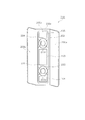
- FIG. 5 is a view of the wear plate assembly 42 as seen from the direction of the arrow X in FIG.
- two adjacent wear plates 200 are shown.
- one of the two adjacent wear plates 200 is referred to as a first wear plate 200P, and the other is referred to as a second wear plate 200Q.
- the planar shape of the wear plate 200 described below is common to all five wear plates 200.
- the first wear plate 200P has a first end side 300 that defines an end on the second wear plate 200Q side.
- “to define” means that a contour of a certain member or a certain region is defined.
- the first end side 300 is opposed to the second wear plate 200Q with a predetermined gap.
- the first end side 300 includes a first end portion 301, a second end portion 302, and a first center portion 303.
- the first end 301 defines the end of the first crawler belt contact surface 200a on the second wear plate 200Q side.
- the first end 301 is located outside the first central portion 303. That is, the first end 301 is located on the outermost side of the first end side 300 when the crawler type traveling device 1 is attached to the work machine.
- the first end 301 is linearly provided.
- the first end 301 is inclined with respect to the axial direction.
- the first end 301 extends in a direction that intersects the axial direction.
- the second end portion 302 defines the end of the second crawler belt contact surface 200b on the second wear plate 200Q side.
- the second end portion 302 is located inside the first center portion 303. That is, the second end portion 302 is located on the innermost side of the first end side 300 when the crawler type traveling device 1 is attached to the work machine.
- the second end portion 302 is linearly provided.
- the second end 302 is inclined with respect to the axial direction.
- the second end 302 extends in a direction that intersects the axial direction. In the present embodiment, the second end portion 302 is parallel to the first end portion 301.
- the first central portion 303 is provided between the first end portion 301 and the second end portion 302 and is continuous with both.
- the first central portion 303 is located at the center of the first end side 300.
- the 1st center part 303 is provided in linear form.
- the first central portion 303 is parallel to the axial direction.
- the first central portion 303 extends along the axial direction. Accordingly, the first central portion 303 is inclined with respect to each of the first end portion 301 and the second end portion 302.
- the second wear plate 200Q has a second end side 400 that defines an end on the first wear plate 200P side.
- the second end side 400 includes a third end portion 401, a fourth end portion 402, and a second central portion 403.
- the third end 401 defines the end of the first crawler belt contact surface 200a on the first wear plate 200P side.
- the third end 401 is located outside the second central portion 403. That is, the third end 401 is located on the outermost side of the second end side 400 when the crawler type traveling device 1 is attached to the work machine.
- the third end 401 is linearly provided.
- the third end 401 is inclined with respect to the axial direction.
- the third end 401 extends in a direction that intersects the axial direction.
- the fourth end 402 defines the end of the second crawler belt contact surface 200b on the first wear plate 200P side.
- the fourth end portion 402 is located inside the second central portion 403. That is, the fourth end portion 402 is located on the innermost side of the second end side 400 when the crawler type traveling device 1 is attached to the work machine.
- the fourth end portion 402 is provided in a straight line shape.
- the fourth end portion 402 is inclined with respect to the axial direction.
- the fourth end portion 402 extends in a direction that intersects the axial direction. In the present embodiment, the fourth end portion 402 is parallel to the third end portion 401.
- the second central portion 403 is provided between the third end portion 401 and the fourth end portion 402, and is continuous with both.
- the second center portion 403 is located at the center of the second end side 400.
- the second central portion 403 is provided in a straight line.
- the second central portion 403 is parallel to the axial direction.
- the second central portion 403 extends along the axial direction. Accordingly, the second central portion 403 is inclined with respect to each of the third end portion 401 and the fourth end portion 402.
- the second end 400 of the second wear plate 200Q is along the first end 300 of the first wear plate 200P.
- the first end 301 of the first end side 300 is parallel to the third end 401 of the second end side 400.
- the second end 302 of the first end side 300 is parallel to the fourth end 402 of the second end side 400.
- the first center portion 303 of the first end side 300 is parallel to the second center portion 403 of the second end side 400.
- first end side 300 and the second end side 400 are point symmetric with respect to the symmetry center CP.
- the center of symmetry CP is located approximately at the center of the gap 200R between the first wear plate 200P and the second wear plate 200Q.
- the planar shape of the gap 200R is also point-symmetric with respect to the symmetry center CP.
- the peripheral surface 41a of the idler body 41 and the support portion 100 are exposed inside the gap 200R.
- the wear plate assembly 42 includes an arcuate wear plate 200, a first fixing plate 201, and a first fastener 203.
- the wear plate 200 is disposed on the peripheral surface 41 a of the idler body 41.
- the first fixing plate 201 fixes the wear plate 200 to the idler body 41.
- the first fastener 203 fastens the first fixing plate 201 to the idler body 41.
- Wear plate 200 includes first and second crawler belt contact surfaces 200a and 200b, a guide portion 200c, a first contact surface 200S, and a second contact surface 200T.
- the guide part 200c protrudes from the first and second crawler belt contact surfaces 200a.
- the first contact surface 200S is in contact with the idler body 41 and is perpendicular to the axial direction of the rotation center axis AX.
- the second contact surface 200T contacts the idler body 41 and is perpendicular to the axial direction.
- the first contact surface 200S faces the second contact surface 200T in the axial direction.
- the wear plate 200 is axially moved when an axial force is applied from the crawler belt 50 to the guide portion 200c. Can be suppressed.
- the first fastener 203 since no force is applied to the first fastener 203 via the first fixing plate 201, the first fastener 203 can be prevented from being damaged.
- the wear plate 200 has an opening 200d.
- the idler body 41 has a convex portion 100 that is formed on the peripheral surface 41a and is disposed in the opening.
- Each of the first contact surface 200S and the second contact surface 200T is a part of the inner surface Sd of the opening 200d and is in contact with the convex portion 100.
- the wear plate 200 can be reduced in size and weight as compared with the case where a part of the wear plate 200 is brought into contact with the outer surface 41b and the inner surface 41c of the idler body 41.
- the wear plate assembly 42 includes a second fixed plate 202 and a second fastener 204.
- the second fixing plate 202 fixes the wear plate 200 to the idler body 41.
- the second fastener 204 fastens the second fixing plate 202 to the idler body 41.
- the first fixed plate 201 is separated from the second fixed plate 202 in the circumferential direction.
- the wear plate 200 can be fixed by the first fixed plate 201 and the second fixed plate 202, it is possible to suppress a part of the wear plate 200 from being lifted from the idler body 41 when the wear plate 200 is pressed by the crawler belt 50. .
- the opening 200d of the wear plate 200 extends in the circumferential direction.
- the first fixed plate 201 and the second fixed plate 202 are disposed in the opening 200d.
- the wear plate 200 can be further reduced in weight by increasing the size of the opening 200d.
- the wear plate 200 includes a first locking portion 200e and a first buffer member 205.
- the first locking portion 200e is locked between the first fixing plate 201 and the idler body 41.
- the first buffer member 205 is disposed between the first locking portion 200e and the first fixed plate 201.
- the first end 300 of the first wear plate 200P includes a first end 301 and a second end 302.
- the first end 301 is inclined with respect to the axial direction.
- the crawler belt 50 and the first wear plate 200P abut on the pair of flat tread surfaces 51a and the arc-shaped first and second crawler belt contact surfaces 200a, 200b, the abutment portions of both are approximately the axis AX. Is in surface contact in a region with a small width parallel to the. Such a contact portion can be considered to move in the circumferential direction on the first and second crawler belt contact surfaces 200a, 200b, and the first wear plate 200P is worn at the contact portion.
- the contact portion moves on the first crawler belt contact surface 200a and reaches the first end portion 301.
- the contact area between the crawler belt 50 and the first wear plate 200P is reduced, and the contact portion approaches the state of line contact. Therefore, the load pressure applied to the vicinity of the first end 301 is rapidly increased, and wear in the vicinity of the first end 301 is locally promoted.
- the first end 301 is inclined with respect to the axial direction. Therefore, it is possible to suppress the line contact between the crawler belt 50 and the first crawler belt contact surface 200a. Therefore, since the load pressure applied to the vicinity of the first end portion 301 can be reduced, local wear in the vicinity of the first end portion 301 can be suppressed.
- This effect can also be obtained by inclining the second end portion 302 with respect to the axial direction.
- the second end 400 of the second wear plate 200Q includes a third end 401 and a fourth end 402.
- the third end 401 is inclined with respect to the axial direction.
- This effect can also be obtained by inclining the fourth end portion 402 with respect to the axial direction.
- the second end side 400 is along the first end side 300.
- the first end side 300 and the second end side 400 are point symmetric with respect to the symmetry center CP.
- the productivity of the wear plate 200 can be increased.
- the sprocket 30 is disposed behind the track frame BR> ⁇ 10, but may be disposed in front of the track frame 10.
- the idler 40 only needs to be arranged on the opposite side of the sprocket 30 via the track frame 10, and in this case, the idler 40 is arranged behind the track frame 10.
- the support portion 100 is continuously formed over the entire circumference of the peripheral surface 41a, but may be formed intermittently in the circumferential direction.
- the wear plate assembly 42 includes the first buffer member 205 and the second buffer member 206, but may not include these.
- each of the first contact surface 200S and the second contact surface 200T is a part of the inner surface Sd of the opening 200d, and is in contact with the convex portion 100 of the idler body 41.
- Each of the first contact surface 200S and the second contact surface 200T only needs to be perpendicular to the axial direction and face each other.
- the wear plate 200 includes a first extension portion 210 extending on the outer surface 41 b of the idler body 41 and a second extension portion 220 extending on the inner surface 41 c of the idler body 41. You may have.
- a region of the first extending portion 210 that contacts the outer surface 41b is the first abutting surface
- a region of the second extending portion 220 that contacts the inner surface 41c is the second abutting surface 200T.
- the outer surface 41b and the inner surface 41c are contacted surfaces.
- the size and shape of the first contact surface and the second contact surface can be freely designed.
- the displacement of the plate 200 can be more effectively suppressed.
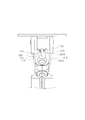
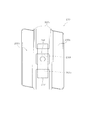
- the wear plate 200 has the pair of first locking portions 200e separated from each other on the left and right, but is not limited thereto. As shown in FIG. 7, one first locking portion 200e may be formed by connecting a pair of first locking portions 200e to the left and right. Similarly, one second locking portion 200f may be formed by connecting a pair of second locking portions 200f to the left and right. In this case, the wear plate assembly 42 only needs to include one fixing member 207 fastened by one first fastener 208 as shown in FIG.
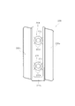
- the wear plate 200 has the pair of first locking portions 200e and the pair of second locking portions 200f, but the present invention is not limited to this. As shown in FIG. 8, the wear plate 200 may have one locking portion 200g. In this case, the wear plate assembly 42 only needs to include one fixing member 209 that is fastened by the first and second fasteners 203 and 204.
- the wear plate 200 has a substantially rectangular shape with the opening 200d at the center when the idler body 41 is viewed from the radial direction, but the present invention is not limited to this. is not.
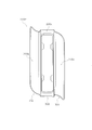
- the wear plate 200 may be H-shaped as viewed in the radial direction as shown in FIGS. 7 and 8, or may be U-shaped as shown in FIG.
- the first fixing plate 201 has been described as an example of the first fixing member in the above embodiment, the present invention is not limited to this. As long as the wear plate 200 can be indirectly fixed to the idler body 41 by the first fastener 203, the first fixing member may have any shape. Therefore, the first fixing member may have a round bar shape, a square bar shape, or a cube shape in addition to the plate shape. The same applies to the second fixing plate 202 described as an example of the second fixing member.
- the first edge 300 of the first wear plate 200P has the first central portion 303.
- the second end 400 of the second wear plate 200Q has the same applies to the second end 400 of the second wear plate 200Q.
- each of the first end 301, the second end 302, and the first center 303 of the first end 300 of the first wear plate 200P is formed in a straight line.
- the first end 301 and the second end 302 may be curved.
- the 1st center part 303 may also be curvilinear. The same applies to the second end 400 of the second wear plate 200Q.
- the second end 302 of the first end 300 of the first wear plate 200P is parallel to the first end 301.
- the present invention is not limited to this. As shown in FIG. 12, the second end 302 may not be parallel to the first end 301.
- the extending directions of the first end 301 and the second end 302 can be changed as appropriate. The same applies to the second end 400 of the second wear plate 200Q.
- each of the first end 301 and the second end 302 of the first end 300 of the first wear plate 200P is inclined with respect to the axial direction. Only one of the first end 301 and the second end 302 may be inclined with respect to the axial direction. The same applies to the second end 400 of the second wear plate 200Q.
- the load pressure received from the crawler track 50 tends to be high on the first crawler track contact surface 200a located outside the second crawler track contact surface 200b. Therefore, when only one of the first end 301 and the second end 302 is inclined with respect to the axial direction, it is preferable to incline the first end 301 located outside the second end 302. .
- the first central portion 303 of the first end 300 of the first wear plate 200P is parallel to the axial direction.
- the first central portion 303 may be inclined with respect to the axial direction.
- the 1st end part 301, the 1st center part 303, and the 2nd end part 302 may continue in a straight line form. The same applies to the second end 400 of the second wear plate 200Q.
- first end side 300 and the second end side 400 are point-symmetric with respect to the symmetry center CP, but the present invention is not limited to this.
- the second end side 400 may be formed so as to be approximately along the first end side 300.
- an idler and a crawler type traveling device capable of suppressing breakage of a fastener for fixing a wear plate, which is useful in the field of idlers and work machines.
Landscapes
- Engineering & Computer Science (AREA)
- Chemical & Material Sciences (AREA)
- Combustion & Propulsion (AREA)
- Transportation (AREA)
- Mechanical Engineering (AREA)
- Devices For Conveying Motion By Means Of Endless Flexible Members (AREA)
- Jib Cranes (AREA)
- Gears, Cams (AREA)
- General Details Of Gearings (AREA)
Abstract
Description
図1は、実施形態に係る履帯式走行装置1の側面図である。履帯式走行装置1は、トラックフレーム10と、アイドラ移動機構20、スプロケット30と、アイドラ40と、履帯50と、2つの上転輪60と、6つの下転輪70とを備える。
図2は、アイドラ40の斜視図である。図3は、摩耗プレートアッセンブリ42の平面図である。図4は、図1のA-A断面図である。図2では、アイドラ40の構成を説明するために1つの摩耗プレートアッセンブリ42が分解されている。
次に、摩耗プレート200の平面形状について、図面を参照しながら説明する。図5は、図2の矢印X方向から摩耗プレートアッセンブリ42を見た矢視図である。図5では、隣接する2つの摩耗プレート200が図示されている。以下においては、隣接する2つの摩耗プレート200のうち一方を第1摩耗プレート200Pと称し、他方を第2摩耗プレート200Qと称する。なお、以下に説明する摩耗プレート200の平面形状は、5枚の摩耗プレート200すべてに共通しているものとする。
(1)実施形態に係る摩耗プレートアッセンブリ42は、円弧状の摩耗プレート200と、第1固定プレート201と、第1締結具203とを有する。摩耗プレート200は、アイドラ本体41の周面41a上に配置される。第1固定プレート201は、摩耗プレート200をアイドラ本体41に固定する。第1締結具203は、第1固定プレート201をアイドラ本体41に締結する。摩耗プレート200は、第1及び第2履帯接触面200a,200bと、ガイド部200cと、第1当接面200Sと、第2当接面200Tとを含む。ガイド部200cは、第1及び第2履帯接触面200aから突出する。第1当接面200Sは、アイドラ本体41と当接し、回転中心軸AXの軸方向に対して垂直である。第2当接面200Tは、アイドラ本体41と当接し、軸方向に対して垂直である。第1当接面200Sは、軸方向において第2当接面200Tと対向する。
以上、本発明の一実施形態について説明したが、本発明は上記実施形態に限定されるものではなく、発明の要旨を逸脱しない範囲で種々の変更が可能である。
10 トラックフレーム
30 スプロケット
40 アイドラ
41 アイドラ本体
41a 周面
41b 外面
41c 内面
41d 挿通孔
41e 凸部
42 摩耗プレートアッセンブリ
50 履帯
100 支持部
101 第1ボス
102 第2ボス
200 摩耗プレート
200S 第1当接面
200T 第2当接面
200a 第1履帯接触面
200b 第2履帯接触面
200c ガイド部
200d 開口部
200e 第1係止部
200f 第2係止部
201 第1固定プレート(第1固定部材)
202 第2固定プレート(第2固定部材)
203 第1締結具
204 第2締結具
205 第1緩衝部材
206 第2緩衝部材
210 第1延在部
220 第2延在部
AX 回転中心軸
Claims (14)
- 履帯が巻回されるアイドラであって、
回転中心軸を有する円盤状のアイドラ本体と、
前記アイドラ本体の周面を取り囲むように配置される複数の摩耗プレートアッセンブリと、
を備え、
前記複数の摩耗プレートアッセンブリそれぞれは、
前記アイドラ本体の前記周面上に配置される円弧状の摩耗プレートと、
前記摩耗プレートを前記アイドラ本体に固定するための第1固定部材と、
前記第1固定部材を前記アイドラ本体に締結するための第1締結具と、
を有し、
前記摩耗プレートは、
前記履帯に接触する履帯接触面と、
前記履帯接触面から突出し、前記履帯を前記履帯接触面上にガイドするためのガイド部と、
前記アイドラ本体と当接し、前記回転中心軸の軸方向に対して垂直な第1当接面と、
前記アイドラ本体と当接し、前記軸方向に対して垂直な第2当接面と、
を含み、
前記第1当接面は、前記軸方向において前記第2当接面と対向する、
アイドラ。 - 前記摩耗プレートは、開口部を有し、
前記アイドラ本体は、前記周面に形成され、前記開口部内に配置される凸部を有し、
前記第1当接面と前記第2当接面のそれぞれは、前記開口部の内側面の一部であり、前記凸部に当接する、
請求項1に記載のアイドラ。 - 前記ガイド部は、前記開口部周縁に設けられる、
請求項2に記載のアイドラ。 - 前記第1固定部材は、前記開口部内に配設される、
請求項2に記載のアイドラ。 - 前記アイドラ本体は、前記周面に連なる外面と、前記周面に連なり前記外面の反対側に設けられる内面とを有し、
前記摩耗プレートは、前記外面上に延在する第1延在部と、前記内面上に延在する第2延在部とを有し、
前記第1当接面は、前記外面に当接し、
前記第2当接面は、前記内面に当接する、
請求項1に記載のアイドラ。 - 前記複数の摩耗プレートアッセンブリそれぞれは、
前記摩耗プレートを前記アイドラ本体に固定するための第2固定部材と、
前記第2固定部材を前記アイドラ本体に締結するための第2締結具と、
を有し、
前記第1固定部材は、前記回転中心軸周りの周方向において前記第2固定部材から離間している、
請求項1に記載のアイドラ。 - 前記摩耗プレートの前記ガイド部は、前記周方向に延びる開口部を有し、
前記第1固定部材と前記第2固定部材は、前記開口部内に配置される、
請求項6に記載のアイドラ。 - 前記摩耗プレートは、
前記第1固定部材と前記アイドラ本体の間に係止される第1係止部と、
記第1係止部と前記第1固定部材の間に配置される第1緩衝部材と、
を有する、
請求項1乃至7のいずれかに記載のアイドラ。 - 前記複数の摩耗プレートアッセンブリは、互いに隣接する第1摩耗プレートと第2摩耗プレートを含み、
前記第1摩耗プレートと前記第2摩耗プレートのそれぞれは、第1履帯接触面と第2履帯接触面を含んでおり、
前記第1摩耗プレートは、平面視において、前記第1履帯接触面の前記第2摩耗プレート側における端を規定する第1端部と、前記第2履帯接触面の前記第2摩耗プレート側における端を規定する第2端部とを含み、
前記第1端部は、前記軸方向に対して傾斜している、
請求項1乃至8のいずれかに記載のアイドラ。 - 前記第2端部は、前記軸方向に対して傾斜している、
請求項9に記載のアイドラ。 - 前記第2摩耗プレートは、平面視において、前記第1履帯接触面の前記第1摩耗プレート側における端を規定する第3端部と、前記第2履帯接触面の前記第1摩耗プレート側における端を規定する第4端部とを含み、
前記第3端部は、前記軸方向に対して傾斜している、
請求項9又は10に記載のアイドラ。 - 前記第4端部は、前記軸方向に対して傾斜している、
請求項11に記載のアイドラ。 - 前記第1端部と前記第3端部は、平面視において所定の対称中心点を基準として点対称であり、
前記第2端部と前記第4端部は、平面視において前記所定の対称中心点を基準として点対称である、
請求項12に記載のアイドラ。 - トラックフレームと、
前記トラックフレームの前方又は後方に配置されるスプロケットと、
前記トラックフレームを介して前記スプロケットの反対側に配置される請求項1乃至13のいずれかに記載のアイドラと、
前記スプロケットと前記アイドラに巻回される履帯と、
を備える履帯式走行装置。
Priority Applications (6)
| Application Number | Priority Date | Filing Date | Title |
|---|---|---|---|
| KR1020167021892A KR101878277B1 (ko) | 2014-04-16 | 2014-04-16 | 아이들러 및 엔드레스 트랙식 주행 장치 |
| DE112014006599.4T DE112014006599B4 (de) | 2014-04-16 | 2014-04-16 | Spannrad und Fahrvorrichtung vom Raupentyp |
| CN201480075704.3A CN106029485B (zh) | 2014-04-16 | 2014-04-16 | 惰轮以及履带式行驶装置 |
| PCT/JP2014/060851 WO2015159393A1 (ja) | 2014-04-16 | 2014-04-16 | アイドラ及び履帯式走行装置 |
| US15/121,890 US9902443B2 (en) | 2014-04-16 | 2014-04-16 | Idler wheel and crawler-type travel device |
| JP2014536461A JPWO2015159393A1 (ja) | 2014-04-16 | 2014-04-16 | アイドラ及び履帯式走行装置 |
Applications Claiming Priority (1)
| Application Number | Priority Date | Filing Date | Title |
|---|---|---|---|
| PCT/JP2014/060851 WO2015159393A1 (ja) | 2014-04-16 | 2014-04-16 | アイドラ及び履帯式走行装置 |
Publications (1)
| Publication Number | Publication Date |
|---|---|
| WO2015159393A1 true WO2015159393A1 (ja) | 2015-10-22 |
Family
ID=54323635
Family Applications (1)
| Application Number | Title | Priority Date | Filing Date |
|---|---|---|---|
| PCT/JP2014/060851 Ceased WO2015159393A1 (ja) | 2014-04-16 | 2014-04-16 | アイドラ及び履帯式走行装置 |
Country Status (6)
| Country | Link |
|---|---|
| US (1) | US9902443B2 (ja) |
| JP (1) | JPWO2015159393A1 (ja) |
| KR (1) | KR101878277B1 (ja) |
| CN (1) | CN106029485B (ja) |
| DE (1) | DE112014006599B4 (ja) |
| WO (1) | WO2015159393A1 (ja) |
Cited By (1)
| Publication number | Priority date | Publication date | Assignee | Title |
|---|---|---|---|---|
| JP2024502250A (ja) * | 2020-12-21 | 2024-01-18 | キャタピラー インコーポレイテッド | ボルトオンフラットアイドラセグメント |
Families Citing this family (6)
| Publication number | Priority date | Publication date | Assignee | Title |
|---|---|---|---|---|
| DE112014006593B4 (de) * | 2014-04-16 | 2018-09-13 | Komatsu Ltd. | Spannrad, Fahrvorrichtung vom Raupentyp und Verschleißplatte |
| CN109501878B (zh) * | 2018-12-26 | 2024-02-02 | 江苏徐工工程机械研究院有限公司 | 组合式履带板、履带总成、履带式行走装置和工程机械 |
| US11535319B2 (en) * | 2019-05-06 | 2022-12-27 | Caterpillar Inc. | Undercarriage noise damping assembly |
| US11878750B2 (en) * | 2020-01-17 | 2024-01-23 | Caterpillar Inc. | Wear inserts cast in a wear surface of a drive component |
| US11613316B2 (en) * | 2020-01-28 | 2023-03-28 | Caterpillar Inc. | Flip-flop track idlers |
| KR102558222B1 (ko) * | 2022-11-28 | 2023-07-24 | 북두산업 주식회사 | 플랜지 보강형 아이들러 및 이의 제조방법 |
Citations (5)
| Publication number | Priority date | Publication date | Assignee | Title |
|---|---|---|---|---|
| JPS4523070Y1 (ja) * | 1966-08-18 | 1970-09-11 | ||
| JPS5047133U (ja) * | 1973-08-28 | 1975-05-10 | ||
| JPS613082U (ja) * | 1984-06-08 | 1986-01-09 | 株式会社小松製作所 | 装軌式車両のアイドラ装置 |
| US20100102623A1 (en) * | 2008-10-24 | 2010-04-29 | Mulligan Patrick J | Track idler with replaceable wear pads |
| JP2014004957A (ja) * | 2012-06-26 | 2014-01-16 | Kobelco Contstruction Machinery Ltd | コンプレッサ取付用ブラケットおよびそれを備えた建設機械 |
Family Cites Families (10)
| Publication number | Priority date | Publication date | Assignee | Title |
|---|---|---|---|---|
| US3603650A (en) * | 1969-02-18 | 1971-09-07 | Robert L Miller | Wheel liners for track-type vehicle |
| US4034618A (en) * | 1976-03-22 | 1977-07-12 | Caterpillar Tractor Co. | Noise reducing apparatus for track type vehicle drive sprockets and means for attaching same |
| JPS5766077A (en) * | 1980-10-13 | 1982-04-22 | Caterpillar Mitsubishi Ltd | Reducer for noise around idler of crawler type vehicle |
| US4818041A (en) | 1988-04-04 | 1989-04-04 | Caterpillar Inc. | Idler wheel assembly for track-type vehicle |
| JP2546091B2 (ja) | 1991-09-30 | 1996-10-23 | 井関農機株式会社 | クロ−ラ式走行装置 |
| JPH0613082U (ja) * | 1992-07-16 | 1994-02-18 | 株式会社ジャルコ | プラグインタイプのオ−ディオコネクタにおけるア−スラグの構造 |
| JP2002002564A (ja) | 2000-06-28 | 2002-01-09 | Komatsu Ltd | 履帯走行装置 |
| US20100072813A1 (en) * | 2007-01-16 | 2010-03-25 | Mcrae Brian Donald | Crawler Tracks and Idlers for Crawler Tracks |
| US20080217994A1 (en) * | 2007-03-06 | 2008-09-11 | Mcrae Brian Donald | Idler for crawler track |
| US8360535B2 (en) * | 2008-12-02 | 2013-01-29 | Caterpillar Inc. | Sound reducing segmented idler for track-type vehicles |
-
2014
- 2014-04-16 DE DE112014006599.4T patent/DE112014006599B4/de active Active
- 2014-04-16 KR KR1020167021892A patent/KR101878277B1/ko not_active Expired - Fee Related
- 2014-04-16 US US15/121,890 patent/US9902443B2/en active Active
- 2014-04-16 WO PCT/JP2014/060851 patent/WO2015159393A1/ja not_active Ceased
- 2014-04-16 CN CN201480075704.3A patent/CN106029485B/zh active Active
- 2014-04-16 JP JP2014536461A patent/JPWO2015159393A1/ja active Pending
Patent Citations (5)
| Publication number | Priority date | Publication date | Assignee | Title |
|---|---|---|---|---|
| JPS4523070Y1 (ja) * | 1966-08-18 | 1970-09-11 | ||
| JPS5047133U (ja) * | 1973-08-28 | 1975-05-10 | ||
| JPS613082U (ja) * | 1984-06-08 | 1986-01-09 | 株式会社小松製作所 | 装軌式車両のアイドラ装置 |
| US20100102623A1 (en) * | 2008-10-24 | 2010-04-29 | Mulligan Patrick J | Track idler with replaceable wear pads |
| JP2014004957A (ja) * | 2012-06-26 | 2014-01-16 | Kobelco Contstruction Machinery Ltd | コンプレッサ取付用ブラケットおよびそれを備えた建設機械 |
Cited By (1)
| Publication number | Priority date | Publication date | Assignee | Title |
|---|---|---|---|---|
| JP2024502250A (ja) * | 2020-12-21 | 2024-01-18 | キャタピラー インコーポレイテッド | ボルトオンフラットアイドラセグメント |
Also Published As
| Publication number | Publication date |
|---|---|
| CN106029485B (zh) | 2018-03-23 |
| US9902443B2 (en) | 2018-02-27 |
| DE112014006599B4 (de) | 2022-05-12 |
| JPWO2015159393A1 (ja) | 2017-04-13 |
| KR20160106732A (ko) | 2016-09-12 |
| US20170120971A1 (en) | 2017-05-04 |
| KR101878277B1 (ko) | 2018-07-13 |
| CN106029485A (zh) | 2016-10-12 |
| DE112014006599T5 (de) | 2017-03-30 |
Similar Documents
| Publication | Publication Date | Title |
|---|---|---|
| JPWO2015159393A1 (ja) | アイドラ及び履帯式走行装置 | |
| US20150321712A1 (en) | Rubber crawler | |
| JP5851546B2 (ja) | クローラ | |
| US20100270856A1 (en) | Crawler-type travel device and rotational wheel assembly | |
| CN107532702A (zh) | 链轮凸缘 | |
| CA2463399A1 (en) | Wheel assembly for a tracked vehicle | |
| JP2006213165A (ja) | 雪上車 | |
| US9758306B2 (en) | Continuous conveyor | |
| JP6220055B2 (ja) | アイドラ、履帯式走行装置及び摩耗プレート | |
| US10710653B2 (en) | Self aligning idler wheel design for rubber tracks | |
| JP2006111253A (ja) | チェーン駆動を用いる芯金無しゴムクローラーを備えたアンダーキャリッジ{undercarriageequippedwithanon−steeltyperubbercrawlerusingchainaction} | |
| JPWO2017068688A1 (ja) | 走行体および作業車両 | |
| JP5966047B2 (ja) | アイドラ及び履帯式走行装置 | |
| JP5213377B2 (ja) | ゴムクローラ | |
| US5433515A (en) | Guide rollers for flexible drive belt | |
| US12065205B2 (en) | Sprocket with a roller assembly inserted into the sprocket teeth | |
| WO2017017958A1 (ja) | 弾性クローラ | |
| JP7394698B2 (ja) | ゴムクローラの起動輪、駆動機構、及び車両 | |
| JP2015202784A (ja) | クローラ | |
| JP2016107990A (ja) | クローラ | |
| JP2015014329A (ja) | チェーンガイド | |
| JP2010241226A (ja) | 突起駆動型ゴムクローラ |
Legal Events
| Date | Code | Title | Description |
|---|---|---|---|
| ENP | Entry into the national phase |
Ref document number: 2014536461 Country of ref document: JP Kind code of ref document: A |
|
| 121 | Ep: the epo has been informed by wipo that ep was designated in this application |
Ref document number: 14889443 Country of ref document: EP Kind code of ref document: A1 |
|
| ENP | Entry into the national phase |
Ref document number: 20167021892 Country of ref document: KR Kind code of ref document: A |
|
| WWE | Wipo information: entry into national phase |
Ref document number: 15121890 Country of ref document: US |
|
| WWE | Wipo information: entry into national phase |
Ref document number: 112014006599 Country of ref document: DE |
|
| 122 | Ep: pct application non-entry in european phase |
Ref document number: 14889443 Country of ref document: EP Kind code of ref document: A1 |