WO2015156320A1 - 高濃度に硫黄成分を含有する低質燃料を使用する船舶用ディーゼルエンジンの排ガス処理装置 - Google Patents
高濃度に硫黄成分を含有する低質燃料を使用する船舶用ディーゼルエンジンの排ガス処理装置 Download PDFInfo
- Publication number
- WO2015156320A1 WO2015156320A1 PCT/JP2015/060982 JP2015060982W WO2015156320A1 WO 2015156320 A1 WO2015156320 A1 WO 2015156320A1 JP 2015060982 W JP2015060982 W JP 2015060982W WO 2015156320 A1 WO2015156320 A1 WO 2015156320A1
- Authority
- WO
- WIPO (PCT)
- Prior art keywords
- exhaust gas
- pipe
- concentration
- low
- cyclone
- Prior art date
Links
Images


Classifications
-
- F—MECHANICAL ENGINEERING; LIGHTING; HEATING; WEAPONS; BLASTING
- F01—MACHINES OR ENGINES IN GENERAL; ENGINE PLANTS IN GENERAL; STEAM ENGINES
- F01N—GAS-FLOW SILENCERS OR EXHAUST APPARATUS FOR MACHINES OR ENGINES IN GENERAL; GAS-FLOW SILENCERS OR EXHAUST APPARATUS FOR INTERNAL COMBUSTION ENGINES
- F01N3/00—Exhaust or silencing apparatus having means for purifying, rendering innocuous, or otherwise treating exhaust
- F01N3/02—Exhaust or silencing apparatus having means for purifying, rendering innocuous, or otherwise treating exhaust for cooling, or for removing solid constituents of, exhaust
- F01N3/037—Exhaust or silencing apparatus having means for purifying, rendering innocuous, or otherwise treating exhaust for cooling, or for removing solid constituents of, exhaust by means of inertial or centrifugal separators, e.g. of cyclone type, optionally combined or associated with agglomerators
-
- B—PERFORMING OPERATIONS; TRANSPORTING
- B01—PHYSICAL OR CHEMICAL PROCESSES OR APPARATUS IN GENERAL
- B01D—SEPARATION
- B01D53/00—Separation of gases or vapours; Recovering vapours of volatile solvents from gases; Chemical or biological purification of waste gases, e.g. engine exhaust gases, smoke, fumes, flue gases, aerosols
- B01D53/32—Separation of gases or vapours; Recovering vapours of volatile solvents from gases; Chemical or biological purification of waste gases, e.g. engine exhaust gases, smoke, fumes, flue gases, aerosols by electrical effects other than those provided for in group B01D61/00
- B01D53/323—Separation of gases or vapours; Recovering vapours of volatile solvents from gases; Chemical or biological purification of waste gases, e.g. engine exhaust gases, smoke, fumes, flue gases, aerosols by electrical effects other than those provided for in group B01D61/00 by electrostatic effects or by high-voltage electric fields
-
- B—PERFORMING OPERATIONS; TRANSPORTING
- B03—SEPARATION OF SOLID MATERIALS USING LIQUIDS OR USING PNEUMATIC TABLES OR JIGS; MAGNETIC OR ELECTROSTATIC SEPARATION OF SOLID MATERIALS FROM SOLID MATERIALS OR FLUIDS; SEPARATION BY HIGH-VOLTAGE ELECTRIC FIELDS
- B03C—MAGNETIC OR ELECTROSTATIC SEPARATION OF SOLID MATERIALS FROM SOLID MATERIALS OR FLUIDS; SEPARATION BY HIGH-VOLTAGE ELECTRIC FIELDS
- B03C3/00—Separating dispersed particles from gases or vapour, e.g. air, by electrostatic effect
- B03C3/017—Combinations of electrostatic separation with other processes, not otherwise provided for
-
- B—PERFORMING OPERATIONS; TRANSPORTING
- B03—SEPARATION OF SOLID MATERIALS USING LIQUIDS OR USING PNEUMATIC TABLES OR JIGS; MAGNETIC OR ELECTROSTATIC SEPARATION OF SOLID MATERIALS FROM SOLID MATERIALS OR FLUIDS; SEPARATION BY HIGH-VOLTAGE ELECTRIC FIELDS
- B03C—MAGNETIC OR ELECTROSTATIC SEPARATION OF SOLID MATERIALS FROM SOLID MATERIALS OR FLUIDS; SEPARATION BY HIGH-VOLTAGE ELECTRIC FIELDS
- B03C3/00—Separating dispersed particles from gases or vapour, e.g. air, by electrostatic effect
- B03C3/34—Constructional details or accessories or operation thereof
- B03C3/40—Electrode constructions
- B03C3/41—Ionising-electrodes
-
- B—PERFORMING OPERATIONS; TRANSPORTING
- B03—SEPARATION OF SOLID MATERIALS USING LIQUIDS OR USING PNEUMATIC TABLES OR JIGS; MAGNETIC OR ELECTROSTATIC SEPARATION OF SOLID MATERIALS FROM SOLID MATERIALS OR FLUIDS; SEPARATION BY HIGH-VOLTAGE ELECTRIC FIELDS
- B03C—MAGNETIC OR ELECTROSTATIC SEPARATION OF SOLID MATERIALS FROM SOLID MATERIALS OR FLUIDS; SEPARATION BY HIGH-VOLTAGE ELECTRIC FIELDS
- B03C3/00—Separating dispersed particles from gases or vapour, e.g. air, by electrostatic effect
- B03C3/34—Constructional details or accessories or operation thereof
- B03C3/40—Electrode constructions
- B03C3/45—Collecting-electrodes
- B03C3/49—Collecting-electrodes tubular
-
- F—MECHANICAL ENGINEERING; LIGHTING; HEATING; WEAPONS; BLASTING
- F01—MACHINES OR ENGINES IN GENERAL; ENGINE PLANTS IN GENERAL; STEAM ENGINES
- F01N—GAS-FLOW SILENCERS OR EXHAUST APPARATUS FOR MACHINES OR ENGINES IN GENERAL; GAS-FLOW SILENCERS OR EXHAUST APPARATUS FOR INTERNAL COMBUSTION ENGINES
- F01N3/00—Exhaust or silencing apparatus having means for purifying, rendering innocuous, or otherwise treating exhaust
- F01N3/01—Exhaust or silencing apparatus having means for purifying, rendering innocuous, or otherwise treating exhaust by means of electric or electrostatic separators
-
- F—MECHANICAL ENGINEERING; LIGHTING; HEATING; WEAPONS; BLASTING
- F01—MACHINES OR ENGINES IN GENERAL; ENGINE PLANTS IN GENERAL; STEAM ENGINES
- F01N—GAS-FLOW SILENCERS OR EXHAUST APPARATUS FOR MACHINES OR ENGINES IN GENERAL; GAS-FLOW SILENCERS OR EXHAUST APPARATUS FOR INTERNAL COMBUSTION ENGINES
- F01N3/00—Exhaust or silencing apparatus having means for purifying, rendering innocuous, or otherwise treating exhaust
- F01N3/02—Exhaust or silencing apparatus having means for purifying, rendering innocuous, or otherwise treating exhaust for cooling, or for removing solid constituents of, exhaust
-
- B—PERFORMING OPERATIONS; TRANSPORTING
- B01—PHYSICAL OR CHEMICAL PROCESSES OR APPARATUS IN GENERAL
- B01D—SEPARATION
- B01D2257/00—Components to be removed
- B01D2257/30—Sulfur compounds
- B01D2257/302—Sulfur oxides
-
- B—PERFORMING OPERATIONS; TRANSPORTING
- B01—PHYSICAL OR CHEMICAL PROCESSES OR APPARATUS IN GENERAL
- B01D—SEPARATION
- B01D2258/00—Sources of waste gases
- B01D2258/01—Engine exhaust gases
- B01D2258/012—Diesel engines and lean burn gasoline engines
-
- B—PERFORMING OPERATIONS; TRANSPORTING
- B01—PHYSICAL OR CHEMICAL PROCESSES OR APPARATUS IN GENERAL
- B01D—SEPARATION
- B01D2259/00—Type of treatment
- B01D2259/45—Gas separation or purification devices adapted for specific applications
- B01D2259/4566—Gas separation or purification devices adapted for specific applications for use in transportation means
-
- B—PERFORMING OPERATIONS; TRANSPORTING
- B03—SEPARATION OF SOLID MATERIALS USING LIQUIDS OR USING PNEUMATIC TABLES OR JIGS; MAGNETIC OR ELECTROSTATIC SEPARATION OF SOLID MATERIALS FROM SOLID MATERIALS OR FLUIDS; SEPARATION BY HIGH-VOLTAGE ELECTRIC FIELDS
- B03C—MAGNETIC OR ELECTROSTATIC SEPARATION OF SOLID MATERIALS FROM SOLID MATERIALS OR FLUIDS; SEPARATION BY HIGH-VOLTAGE ELECTRIC FIELDS
- B03C2201/00—Details of magnetic or electrostatic separation
- B03C2201/10—Ionising electrode has multiple serrated ends or parts
-
- B—PERFORMING OPERATIONS; TRANSPORTING
- B03—SEPARATION OF SOLID MATERIALS USING LIQUIDS OR USING PNEUMATIC TABLES OR JIGS; MAGNETIC OR ELECTROSTATIC SEPARATION OF SOLID MATERIALS FROM SOLID MATERIALS OR FLUIDS; SEPARATION BY HIGH-VOLTAGE ELECTRIC FIELDS
- B03C—MAGNETIC OR ELECTROSTATIC SEPARATION OF SOLID MATERIALS FROM SOLID MATERIALS OR FLUIDS; SEPARATION BY HIGH-VOLTAGE ELECTRIC FIELDS
- B03C2201/00—Details of magnetic or electrostatic separation
- B03C2201/30—Details of magnetic or electrostatic separation for use in or with vehicles
-
- F—MECHANICAL ENGINEERING; LIGHTING; HEATING; WEAPONS; BLASTING
- F01—MACHINES OR ENGINES IN GENERAL; ENGINE PLANTS IN GENERAL; STEAM ENGINES
- F01N—GAS-FLOW SILENCERS OR EXHAUST APPARATUS FOR MACHINES OR ENGINES IN GENERAL; GAS-FLOW SILENCERS OR EXHAUST APPARATUS FOR INTERNAL COMBUSTION ENGINES
- F01N2590/00—Exhaust or silencing apparatus adapted to particular use, e.g. for military applications, airplanes, submarines
- F01N2590/02—Exhaust or silencing apparatus adapted to particular use, e.g. for military applications, airplanes, submarines for marine vessels or naval applications
-
- Y—GENERAL TAGGING OF NEW TECHNOLOGICAL DEVELOPMENTS; GENERAL TAGGING OF CROSS-SECTIONAL TECHNOLOGIES SPANNING OVER SEVERAL SECTIONS OF THE IPC; TECHNICAL SUBJECTS COVERED BY FORMER USPC CROSS-REFERENCE ART COLLECTIONS [XRACs] AND DIGESTS
- Y02—TECHNOLOGIES OR APPLICATIONS FOR MITIGATION OR ADAPTATION AGAINST CLIMATE CHANGE
- Y02T—CLIMATE CHANGE MITIGATION TECHNOLOGIES RELATED TO TRANSPORTATION
- Y02T10/00—Road transport of goods or passengers
- Y02T10/10—Internal combustion engine [ICE] based vehicles
- Y02T10/12—Improving ICE efficiencies
Definitions
- the present invention removes and purifies harmful gases such as sulfur oxides contained in the exhaust gas of marine diesel engines, and uses heavy oil containing heavy sulfur components [heavy oil (heavy oil ( FuelOil is used in the marine industry in diesel oil (DieselOil: DO), marine diesel fuel (MarineDieselFuel: MDF) or marine diesel oil (MarineDieselOil: MDO), marine fuel oil (MarineFuelOil: MFO), heavy fuel oil (HeOil: Heoil) HFO) and residual fuel oil (ResidualFuelOil: RFO).
- these symbols are collectively referred to as heavy oil (DieselOil).
- the present invention relates to an exhaust gas purifying apparatus provided with a device for collecting PM from exhaust gas and incinerating the collected PM in a ship.
- Diesel engines are widely used as power sources for various ships, power generators, large construction machines, and various automobiles.
- Particulate matter mainly composed of carbon contained in exhaust gas discharged from diesel engines Particulate Matter (hereinafter referred to as “PM”), sulfur oxide (hereinafter referred to as “SOx”), and nitrogen oxide (hereinafter referred to as “NOx”) not only cause air pollution, as is well known. Since it is a substance that is extremely harmful to the human body, purification of the exhaust gas is extremely important.
- exhaust gas recirculation (hereinafter referred to as “EGR”) method, selective catalytic catalytic denitration method (Selective Catalytic Reduction: hereinafter referred to as “exhaust gas recirculation”)
- EGR exhaust gas recirculation
- exhaust gas recirculation selective catalytic catalytic denitration method
- components of PM (particulate matter) in exhaust gas of a diesel engine are organic solvent soluble (SOF: Soluble Organic Fractions, hereinafter referred to as “SOF”) and organic solvent insoluble (ISF: Insoluble Organic Fractions).
- SOF organic solvent soluble
- ISF organic solvent insoluble
- the ISF component is mainly composed of carbon (soot) and sulfate (sulfate) components having low electrical resistivity.
- the SOF component and the ISF component are affected as much as possible because of their effects on the human body and the environment. Less exhaust gas is desired. In particular, it is also said that the degree of adverse effects of PM in a living body is particularly problematic when the particle diameter is nm.
- Patent Documents 1 to 3 have been proposed as a method of performing electrical treatment using corona discharge. That is, the applicant of the present application disclosed in Patent Document 1 as shown in FIG. 7 schematically, by providing a discharge charging portion 122 comprising a corona discharge portion 122-1 and a charging portion 122-2 in the exhaust gas passage 121, The discharged electrons 129 are charged to the PM 128 mainly composed of carbon in the exhaust gas G1, and the charged PM 128 is collected by a collecting plate 123 disposed in the exhaust gas passage 121.
- the electrode needle 124 in 122 is short in the flow direction of the exhaust gas flow, and the collecting plate 123 is disposed in a direction perpendicular to the flow direction of the exhaust gas flow.
- a processing device has been proposed previously. In the figure, 125 is a seal gas pipe, 126 is a high voltage power supply device, and 127 is an exhaust gas induction pipe.
- Patent Document 2 for exhaust gas of a diesel engine in which the cyclone collecting means 132-1 is composed of two tangential cyclones 132-1a as schematically shown in FIG. 8 (A).
- An electrical processing device has been proposed previously.
- two tangential cyclones 132-1a are connected in parallel to the high-concentration exhaust gas outlet section 131-1b of the collection pipe 131-1 via communication pipes 135-1 and 135-2, and the cyclone trapping is performed.
- Exhaust pipes 136-1 and 136-2 for constituting the collecting means 132-1 and for joining the purified gas after passing through each tangential cyclone 132-1a to the low-concentration exhaust gas flowing in the low-concentration exhaust gas outlet pipe 133, respectively.
- this electric processing apparatus for exhaust gas is roughly divided into a tubular collection portion 131 that constitutes an electrostatic dust collection means and a separate collection 132 that constitutes a separate collection means, and collects PM particles.
- the tubular collecting part 131 provided for collecting is a collecting tube 131-1 having a collecting wall 131-1K having a predetermined length constituting the dust collecting electrode and a discharge electrode 131 for charging PM contained in the exhaust gas. -2.
- the collection pipe 131-1 constituting the dust collection electrode has an exhaust gas inlet 131-1a at the upstream (diesel engine side) end, and a PM low-concentration exhaust gas discharge pipe in the vicinity of the downstream axis.
- the discharge electrode 131-2 includes a main electrode 131-2a extending substantially over the entire length of the collection tube 131-1 constituting the dust collection electrode, and radially projecting electrode needles 131-2b spaced from the main electrode. It is composed of groups.
- the discharge electrode 131-2 configured in this manner is provided at the inlet portion of the seal air introduction pipe portion 131-1c provided on the exhaust gas inlet 131-1a side of the collection pipe 131-1 and the low concentration exhaust gas outlet pipe 133. Both ends of the main electrode 131-2a are supported via a support 134 that is suspended from the provided seal air introduction pipe portion 133-1.
- Reference numeral 137 denotes a flow control damper.
- FIG. 3 A tubular diesel engine exhaust gas treatment apparatus having a tubular collection part 141-1 and equipped with a cyclone-type separation and collection means for separating and collecting particulate matter separated from the tubular collection part 141-1.
- Cyclone collecting means 142-1 constituted by a tangential cyclone 142-1a is provided on the pipe from the high concentration exhaust gas deriving unit 141-1b of the particulate matter provided near the inner peripheral surface on the downstream side of the collecting unit 141-1.
- the high concentration exhaust gas flow discharged from the high concentration exhaust gas deriving unit 141-1b is introduced into the tangential cyclone 142-1a to collect and process large-diameter particles.
- the exhaust gas flow containing fine particles that could not be left is given kinetic energy by the blower 147 to increase and increase the pressure, and then pumped to the introduction pipe (exhaust pipe) 141-1a via the reflux pipe 142-2. ⁇ This is a method of refluxing.
- 141-1a is an exhaust gas inlet
- 141-1c and 143-1 are seal air introduction pipe sections
- 141-2a is a main electrode
- 141-2b is an electrode needle
- 143 is a low-concentration exhaust gas outlet pipe
- 144 is a main exhaust pipe
- the electrode support 148 is a flow control damper.
- oil concentration of the oily mixture when not diluted is 15 or less per million”.
- oil refers to crude oil, heavy oil and lubricating oil, “oiliness” is interpreted according to this meaning, and “oily mixture” refers to a mixture containing oil.
- Non-Patent Document 2 discloses a marine diesel engine that can reduce 80% of NOx from exhaust gas and remove nearly 100% of SOx from EGR gas by recirculating EGR gas diverted from exhaust gas to intake air. Has been.
- Non-Patent Document 3 describes an example of an SOx-compatible technology using Alfa Laval's output 21,000 kW, MANBW 2-stroke engine installed in the Danish Fikaria Seaways.
- a scrubber that uses both seawater and fresh water depending on the situation while using 2 percent heavy oil, sulfur in the exhaust gas, which is the required level scheduled for implementation in 2015 by the International Maritime Period (IMO)
- IMO International Maritime Period
- Exhaust gas treatment technology for diesel engine that electrically processes PM in exhaust gas by utilizing corona discharge or the like described in Patent Document 1 (for example, an electric treatment device for exhaust gas of diesel engine shown in FIG. 9) Has the following problems. That is, in the case of marine diesel engines, heavy oils [heavy oils] that have a significantly larger displacement and contain sulfur components at a higher concentration than diesel engines for automobiles that use light oils with a low sulfur content.
- FIG. 8 has a tangential cyclone 132-1a shown in FIG. 8 (A) as a separate collection unit 132, or a plurality of tangential cyclones having different processing capabilities, for example, FIG. 8 (B) uses a complex device consisting of three types of cyclones: small throughput tangential cyclone 132-1b, medium throughput tangential cyclone 132-1c, and high throughput tangential cyclone 132-1d. ing.
- reference numerals 138-1, 138-2, and 138-3 denote communication pipes
- 139-1, 139-2, and 139-3 denote flow control dampers, respectively.
- PM particles are reliably collected by each cyclone while controlling the flow rate of exhaust gas flowing into each cyclone to be optimal, and the low concentration of PM in the gas discharged from each cyclone is reliably reduced and diluted.
- the exhaust gas needs to be joined to the low concentration exhaust gas outlet pipe 133 through the exhaust gas exhaust pipes 136-1 and 136-2, and the engine and the exhaust gas treatment device are continuously operated as in the above-mentioned Patent Document 1.
- a processing unit for a large amount of collected PM that is expected by is not disclosed. *
- Non-Patent Document 1 emission control outside the special sea area, that is, prohibition of oil or oil mixture discharge to the ocean, etc. is established, and the oil content concentration of the oil mixture when not diluted The same applies to the case where PM is contained.
- Non-Patent Document 2 it is possible to reduce NOx by 80% from exhaust gas and remove SOx by nearly 100% from EGR gas by returning the EGR gas diverted from the exhaust gas to the intake air.
- the dust that passes through the scrubber and the sulfur content still contained in the PM will not only require a long-term actual ship test, but also the cleaning exhausted from the scrubber.
- the water should not affect the environment and ecosystem, especially dissolved and suspended in PM in the wash water of this scrubber, these environmental contaminant or ecological influence component due to the dissolution or the like of sO 2 Wastewater treatment such as removal and pH adjustment is expected to be a major problem. That is, even if PM is removed from the EGR gas, PM is not removed from the exhaust gas, and therefore there is no technical idea for processing the collected PM.
- the sulfur oxides in the exhaust gas are further washed in the scrubber tower.
- the water droplets in the gas are removed by a demister before being discharged from the chimney.
- the sulfur oxide remaining in the exhaust gas is further purified. Before discharging from the chimney of the ship, small water droplets are removed from the exhaust gas to prevent condensation and corrosion (removes 98% or more of the sulfur content of the exhaust gas).
- Non-Patent Document 3 on page 12, column 2, line 16 to column 3, line 1 "The scrubber can be said to be a large shower room installed in the funnel of a ship” and a photo on page 14
- Non-Patent Document 3 PM is not captured at all in the seawater mode (see the description on page 12, column 4, line 16 to column 5, line 1).
- an SCR system using a catalytic reaction is generally known as a known NOx reduction technique.
- the catalyst if the catalyst is activated when the exhaust gas temperature of the engine is sufficiently high and the catalyst surface is reliably exposed without being covered with soot or the like, the catalyst functions normally and high NOx. Reduction can be achieved.
- long stroke low speed engines are the mainstream compared to automobile engines, etc., in order to ensure an improvement in fuel consumption rate, and the energy of the combustion gas is slowly spent in the cylinder.
- the temperature of the exhaust gas becomes low due to the reliable removal of power as a motive power and the heat release associated with the contact of the combustion gas with the cylinder wall for a long time.
- the present invention has been made in view of the above-described problems of the prior art.
- high-speed and / or large-flow exhaust gas is discharged with a large displacement using a low-quality fuel such as heavy oil containing a sulfur component at a high concentration.
- the combustion exhaust gas generated at the time of incineration is returned to the collection tube and charged again.
- low-concentration exhaust gas is scrubbed with a PM fleece scrubber, or combustion exhaust gas generated during incineration is scrubbed with a PM fleece scrubber.
- Marine diesel using low quality fuel such as heavy oil containing sulfur component at high concentration, which can reliably collect and remove PM, and can be discharged as gas that can be environmentally protected by removing SOx. It is an object of the present invention to provide an engine exhaust gas treatment device.
- the exhaust gas treatment apparatus for a marine diesel engine that uses a low-quality fuel such as heavy oil containing a sulfur component at a high concentration is a marine diesel that uses a low-quality fuel such as heavy oil that contains a sulfur component at a high concentration.
- An engine exhaust gas treatment device has a discharge electrode for charging particulate matter contained in engine exhaust gas, and a tubular collecting portion of a predetermined length constituting a dust collecting electrode for collecting the charged particulate matter.
- the discharge electrode includes an electrostatic precipitator configured by a main electrode disposed in the tube axial direction in the tubular collecting portion and a plurality of radially projecting electrodes spaced from the main electrode.
- a low-concentration exhaust gas outlet pipe and a high-concentration exhaust gas outlet pipe, a PM fleece scrubber provided in the low-concentration exhaust gas outlet pipe, and particulate matter separated from the tubular collection part are separated by a dust collecting cyclone.
- a dust collecting means for collecting further having an incinerator for incinerating PM collected by the dust collecting means, and combustion exhaust gas generated by the incinerator in the collecting section or an exhaust pipe upstream of the collecting section
- a reflux pipe for refluxing is provided between the incinerator and an exhaust pipe upstream of the collection pipe or upstream of the collection section.
- the apparatus of the present invention is further provided with a return pipe for returning the combustion exhaust gas from the incinerator to the upstream side of the PM fleece scrubber provided in the low concentration exhaust gas outlet pipe, and a return pipe from the dust collecting cyclone, It is preferable that the PM combustion exhaust gas recirculation pipe is coupled, the lower part of the dust collecting cyclone is used as a PM storage stocker, and the PM incinerator is integrated with the lower part of the stocker via a shutter.
- the stocker controls a plurality of gas and scrubber treated water so that the PM can start incineration after the ship has advanced to the dischargeable sea area, a selective shutter is attached to the incinerator, and the shutter is opened and closed to control the time difference. So that it can be sequentially incinerated.
- the incinerator preferably uses a built-in heater (such as an electric heater) or a burner that has a function of heating and controlling the temperature by a controller to incinerate PM.
- the exhaust gas treatment apparatus for marine diesel engines that uses a low-quality fuel such as heavy oil containing a sulfur component at a high concentration has the following effects. That is, the PM in the exhaust gas of a marine diesel engine that emits high-speed and / or large-flow exhaust gas with a large displacement using a low-quality fuel such as heavy oil containing a sulfur component at a high concentration is converted into ESP / C / It is necessary to store all of the PM collected in the cyclone until the ship arrives at the port with the PM treatment facility as a port facility by incinerating the collected PM in the ship and collecting the collected PM.
- the treated water of PM fleece scrubber contains a high concentration of sulfur components but almost all organic solvent soluble components. Since it does not contain it, it has the effects of being able to be discharged into the ocean. In addition, as an incidental effect, it is the technique which can contribute to the improvement of the energy efficiency of the whole ship by collect
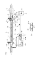
- FIG. 1 shows an apparatus according to a first embodiment of the present invention
- (A) is a schematic longitudinal sectional view showing the overall structure of the apparatus
- (B) shows an example of a structure in which an exhaust gas cooler is provided in an exhaust gas introduction pipe portion of the apparatus.
- It is a schematic longitudinal cross-sectional view.
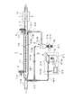
- It is a schematic longitudinal cross-sectional view which shows the whole structure of the 2nd Example apparatus of this invention.
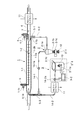
- It is a schematic longitudinal cross-sectional view which shows the whole structure of the 3rd Example apparatus of this invention.
- FIG. 1 It is a schematic longitudinal cross-sectional view which shows the whole structure of the 6th Example apparatus of this invention. It is the schematic which shows an example of the conventional diesel engine exhaust gas processing apparatus. Similarly, it is the schematic which shows the other example of the conventional diesel engine exhaust gas processing apparatus, A figure (A) is a whole block diagram, A figure (B) is the schematic which shows a cyclone collection means. It is the schematic which shows another example of the conventional diesel engine waste gas processing apparatus similarly.
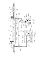
- the exhaust gas treatment device for a marine diesel engine shown as the first embodiment of the present invention is roughly divided into an electric dust collection unit 1, a separate collection unit 2, a PM incineration unit 3 and
- the electrostatic precipitator 1 is provided for collecting PM particles.
- the precipitator 1 has a predetermined length constituting the dust collecting electrode and the discharge electrode 1-2 for charging the PM contained in the exhaust gas.
- the collection pipe 1-1 constituting the dust collection electrode has an exhaust gas introduction pipe 1-1a at the end on the upstream side (diesel engine side), and a low concentration of PM in the vicinity of the axial center at the end on the downstream side.
- the exhaust gas outlet pipe 4 is provided with a PM high-concentration exhaust gas outlet portion 1-1b connected in the vicinity of the inner peripheral surface of the downstream end portion.
- the discharge electrode 1-2 is arranged at a predetermined interval in the longitudinal direction of the main electrode 1-2a extending substantially over the entire length around the axial center of the collection tube 1-1 constituting the dust collection electrode. And a group of radially protruding electrode needles 1-2b.
- the discharge electrode 1-2 configured as described above is provided at the inlet portion of the seal air introduction pipe portion 1-1c provided on the exhaust gas introduction pipe 1-1a side of the collection pipe 1-1 and the low concentration exhaust gas outlet pipe 4. Both ends of the main electrode 1-2a are supported through a support body 5 suspended from the provided seal air introduction pipe section 4-1.
- a PM fleece scrubber 11 that removes SOx contained in the exhaust gas but hardly removes PM is installed in the low-concentration exhaust gas outlet pipe 4 of PM10 by utilizing the difference in the diffusion speed of the gas and particles. SOx is removed from the gas.
- the scrubber-treated water removes SOx from the exhaust gas but hardly removes PM, so that it contains SOx but contains almost no PM and can be easily post-treated as waste treated water of scrubber-treated water.
- the discharge electrode 1-2 is supported at a desired interval by a stage (not shown) insulated from the inside of the collecting tube 1-1 as necessary. Further, the discharge electrode 1-2 is supplied with a controlled high voltage power source by being wired to a high voltage power source device (not shown) installed outside.
- the separation / collection unit 2 provided on the downstream side of the electric dust collection unit 1 in the flow direction of the exhaust gas is constituted by a cyclone collection unit 2-1 as a separation unit.
- the cyclone collecting means 2-1 is composed of a single tangential cyclone 2-1a connected to the high concentration exhaust gas deriving portion 1-1b of the collection pipe 1-1 through a communication pipe 5-1. Further, between the tangential cyclone 2-1a and the low concentration exhaust gas outlet pipe 4, the purified gas after passing through the tangential cyclone 2-1a is joined to the low concentration exhaust gas flowing in the low concentration exhaust gas outlet pipe 4.
- a discharge pipe 6-1 is provided.
- the low-concentration exhaust gas outlet pipe 4 is provided with a flow control damper 7 for adjusting the flow rate of the high-concentration exhaust gas flow rate and flow rate into the tangential cyclone 2-1a and the low-concentration exhaust gas discharge rate.
- the PM10 collected by the tangential cyclone 2-1a accumulates in a detachable hopper 2-1b provided immediately below the cone-shaped portion below the tangential cyclone 2-1a, and the hopper capacity limit is reached. If it reaches, replace it with a new hopper and store it.
- 8 is a stocker for storing PM10.
- the PM incineration unit 3 provided for incineration of PM comprises a PM incinerator 3-1 in which an incineration temperature, an exhaust gas flow rate, and the like are controlled by a controller 3-2, and an electric heater 3-1a is incorporated.
- 12a is a blower that imparts kinetic energy to the exhaust gas flow flowing in the reflux pipe 12. Further, the tip of the reflux pipe 12 is projected into the exhaust gas introduction pipe 1-1a in consideration of the ejector effect, and the tip opening is bent so as to be directed in the exhaust gas outflow direction.
- the PM incinerator 3-1 may be an incinerator using a burner (not shown) instead of the electric heater 3-1a.
- the PM combustion exhaust gas containing a high concentration of the sulfur component generated by incineration of PM10 is recirculated to the collection pipe 1-1 through the recirculation pipe 12 and mixed with the exhaust gas, and at the same time, this PM high concentration mixed flow gas Is led to the tangential cyclone 2-1a, and atmospheric exhaust gas containing a high concentration of sulfur components but a low concentration of PM10 is supplied to the PM fleece clubber 11.
- the PM fleece clubber 11 preserves the atmospheric environment as a gas in which PM remains in the atmospheric exhaust gas, but from which sulfur has been removed.
- the treated water of the PM fleece scrubber 11 contains a high concentration of sulfur components, but contains almost no PM, so it can be discharged to the ocean such as through a scrubber, and can be easily controlled with less man-hours and small size. Can be processed by a simple processing device.
- an exhaust gas cooler 20 is installed in the exhaust gas introduction pipe 1-1a as shown in FIG. 1B, and PM combustion exhaust gas is cooled by the exhaust gas cooling. You may make it recirculate
- FIG. When the exhaust gas cooler 20 is provided in the exhaust gas introduction pipe 1-1a to precool the exhaust gas, if the PM combustion exhaust gas is refluxed downstream of the exhaust gas cooler 20 of the exhaust gas introduction pipe 1-1a, a corrosive substance ( Since PM combustion exhaust gas containing sulfate combustion exhaust gas) does not flow into the exhaust gas cooler 20, it is not necessary to use a highly corrosion-resistant member as a member constituting the exhaust gas cooler 20, and it is inexpensive and durable. Easy to secure. When the PM combustion exhaust gas is recirculated upstream of the exhaust gas cooler 20, the total amount of the gas flowing into the collection pipe 1-1 can be precooled, so that it is high in the electric dust collection unit 1 and the separate collection unit 2. The collection rate can be secured.
- the exhaust gas treatment device for a marine diesel engine shown as the second embodiment of the present invention in FIG. 2 is a reflux type diesel engine exhaust gas treatment device and a PM incinerator using a cyclone of the first embodiment shown in FIG. 1 is charged to the particulate matter contained in the exhaust gas of a marine diesel engine that uses as a fuel a low-quality fuel such as heavy oil containing a sulfur component at a high concentration in the apparatus of the first embodiment shown in FIG. It has a discharge electrode 1-2 and a tubular collecting tube 1-1 that constitutes a dust collecting electrode that collects the charged particulate matter, and separates and captures the separated particulate matter from the tubular collecting tube 1-1.
- It has a cyclone-type separation / collection means 2-1 for collecting, and furthermore, the low concentration exhaust gas outlet pipe 4 of PM 10 removes SOx contained in the exhaust gas by utilizing the difference in diffusion speed of gas and particles, but removes PM.
- An inner peripheral surface on the downstream side of the tubular collection pipe 1-1 of a marine diesel engine exhaust gas treatment apparatus configured to remove the SOx from the exhaust gas released into the atmosphere by installing a PM fleece clubber 11 that is not removed at all.
- the high concentration exhaust gas pipe 5-2 from the PM high concentration exhaust gas deriving unit 1-1b provided in the vicinity is provided with a cyclone collecting means composed of a tangential cyclone 2-1a similar to the above, and the high concentration exhaust gas deriving unit
- a high-concentration exhaust gas stream discharged from 1-1b is introduced into a tangential cyclone 2-1a to collect and process large-diameter particles, and an exhaust gas stream containing fine-diameter particles that could not be removed by the cyclone,
- a system is used in which the exhaust gas is introduced into the exhaust gas introduction pipe 1-1a via the recirculation pipe 14-1, and is refluxed.
- a hopper 2-1b is provided immediately below the cone-shaped portion at the bottom of the tangential cyclone 2-1a, and a shutter for holding and dropping PM collected and accumulated in the hopper immediately below the hopper.
- a stocker 3'-1 having a larger internal volume than the hopper 2-1b also serving as a PM incinerator is provided via 2-1c.
- the stocker 3'-1 also serving as a PM incinerator has a built-in electric heater 3'-1a, and the controller 3-2 controls the incineration temperature, the flow rate of exhaust gas, and the like.
- the shutter 2-1c is opened and the stocker directly under the hopper PM is dropped into 3'-1, and then the shutter 2-1c is closed and stocked.
- Combustion exhaust gas from the stocker 3'-1 that also serves as a PM incinerator is configured to be returned to the exhaust gas introduction pipe 1-1a of the electric dust collector 1 through a return pipe 14-2.
- the leading ends of the reflux pipes 14-1 and 14-2 are projected into the exhaust gas introduction pipe 1-1a in consideration of the ejector effect in the same manner as described above, and the leading end openings are directed to the exhaust gas outflow direction.
- 14-1a and 14-2a are blowers that impart kinetic energy to the exhaust gas flows flowing through the reflux pipes 14-1 and 14-2, respectively. Needless to say, a burner (not shown) may be used in place of the electric heater 3'-1a.
- the high-concentration exhaust gas flow of PM that flows in the vicinity of the inner wall of the collection pipe downstream of the collection pipe 1-1 passes through the collection pipe 1-1.
- the high-concentration exhaust gas outlet 1-1b is introduced into the tangential cyclone 2-1a through the communication pipe 5-1 and the high-concentration exhaust gas pipe 5-2, and the large-diameter PM particles are centrifuged to form a lower cone-shaped part. Collected and deposited in the hopper 2-1b directly below.
- the generally purified exhaust gas stream containing fine PM particles not removed by the tangential cyclone 2-1a is 14-1 flows into the exhaust gas flow flowing in the exhaust gas introduction pipe 1-1a via the upstream communication pipe 5-3. At this time, the purified exhaust gas stream containing small-diameter PM particles is joined.
- kinetic energy is given by the blower 14-1a, and the pressure is increased / accelerated, and the gas is fed / refluxed to the exhaust gas introduction pipe 1-1a by the reflux pipe diameter 14-1.
- the low-concentration exhaust gas flow that flows in the vicinity of the axial center of the collection pipe 1-1 downstream of the collection pipe 1-1 is released to the atmosphere after removing SOx via the PM fleece scrubber 11. ing.
- PM collects and accumulates in the hopper 2-1b provided immediately below the cone-shaped portion below the tangential cyclone 2-1a of the PM incinerator, and when the hopper capacity limit is reached, the shutter 2-1c is installed. Open and drop the PM to drop into the stocker 3'-1 which also serves as a PM incinerator.
- the shutter 2-1c is closed, and the electric heater 3'-1a built in the stocker 3'-1 is burned and incinerated while controlling the incineration temperature, intake air amount, combustion exhaust gas flow rate, etc. by the controller 3-2. Further, the combustion exhaust gas from the PM incinerator is recirculated to the exhaust gas introduction pipe 1-1a of the electrostatic precipitator 1 through the recirculation pipe 14-1a2, so that it also serves as the PM incinerator, for example. Even if PM during combustion in the stocker 3'-1 rises temporarily, it will be reliably removed by going through the electrostatic precipitator 1 and separation / collector 2 again. Therefore, environmental preservation of atmospheric exhaust gas can be achieved.
- the exhaust gas stream (reflux gas) containing fine particles that passed through the cyclone 2-1a is recirculated, pumped, and mixed into the exhaust gas stream from the engine, and again discharged in the collection tube 1-1 ⁇ charge of particles ⁇ collection Adhesion to the inner wall surface of the tube ⁇ Particles can be made larger by repeated peeling, separated as a high-concentration exhaust gas stream, and reliably removed by the cyclone 2-1a.
- B The exhaust gas stream (reflux gas) containing fine particles that passed through the cyclone 2-1a is recirculated, pumped, and mixed into the exhaust gas stream from the engine, and again discharged in the collection tube 1-1 ⁇ charge of particles ⁇ collection Adhesion to the inner wall surface of the tube ⁇ Particles can be made larger by repeated peeling, separated as a high-concentration exhaust gas stream, and reliably removed by the cyclone 2-1a.
- the main engine in the marine engine is maintained or improved in the collection rate of the exhaust gas such as PM, that is, while maintaining or improving the cleanliness of the low concentration exhaust gas.
- the entire system without installing multiple tangential cyclones with different processing capacities in response to changes in operating conditions due to parallel operation or independent operation of auxiliary machines and exhaust gas flow rates that change according to the engine load factor Can be made compact and compact, and the control of the device is simplified, and the control software and device are simplified, making it inexpensive and highly reliable. (C).
- the blower 14-1a By installing the blower 14-1a, the purified exhaust gas stream containing fine PM particles can be smoothly passed through the exhaust gas introduction pipe 1-1a even if the exhaust gas flow resistance of the tangential cyclone 2-1a is somewhat large.
- the inflow tangential speed to the tangential cyclone 2-1a can be appropriately controlled, and the collection efficiency of the cyclone can be increased.
- the installation position of the blower 14-1a may be any position before or after the cyclone. When the blower installation position is upstream of the cyclone, the inflow tangential speed to the cyclone is kept high to easily obtain a high collection rate.
- the blower 14-1a is durable because the suction resistance of the blower 14-1a is large and surging is somewhat feared, but there is little adhesion of PM particles etc. to the fan blade surface and the gas temperature is lowered. Easy to secure.
- the front ends of the recirculation pipes 14-1 and 14-2 are projected into the exhaust gas introduction pipe 1-1a, and the front end opening thereof is bent so as to be directed in the exhaust gas outflow direction. Ejector effect is exerted by jetting the reflux with increased kinetic energy and increased pressure, and the exhaust gas flow flowing through the exhaust gas introduction pipe 1-1a is sucked to reduce exhaust resistance and increase engine efficiency. Can be measured.
- E E).
- the exhaust gas cooler 20 is installed in the exhaust gas introduction pipe 1-1a, and the PM combustion exhaust gas is recirculated downstream of the exhaust gas cooler 20. It goes without saying that this may be done.
- the exhaust gas treatment apparatus for a marine diesel engine shown as the third embodiment of the present invention in FIG. 3 is an electric dust collection section 1 for the combustion exhaust gas from the PM incineration section 3 of the second embodiment apparatus shown in FIG.
- the PM fleece scrubber 11 that is the same as the PM fleece scrubber 11 installed in the low-concentration exhaust gas outlet pipe 4 is installed in the recirculation pipe 14-2 that recirculates to the exhaust gas introduction pipe 1-1a. That is, the configuration is similar to the second embodiment apparatus shown in FIG. 2 in the particulate matter contained in the exhaust gas of marine diesel engines that use low quality fuel such as heavy oil containing a high concentration of sulfur component as fuel.
- It has a discharge electrode 1-2 to be charged and a tubular collecting tube 1-1 that constitutes a dust collecting electrode for collecting the charged particulate matter, and separates the separated particulate material from the tubular collecting tube 1-1.
- Separately collecting cyclone type collecting means 2-1 for collecting, and the low concentration exhaust gas outlet pipe 4 of PM10 removes SOx contained in the exhaust gas by utilizing the difference in diffusion speed of gas and particles, but PM PM fleece scrubber 11 is installed to remove SOx from the exhaust gas discharged to the atmosphere, and PM high concentration exhaust gas derived near the inner peripheral surface on the downstream side of the tubular collecting pipe 1-1 is derived.
- the high-concentration exhaust gas pipe 5-2 is provided with a cyclone collecting means composed of a tangential cyclone 2-1a similar to the above, and the high-concentration exhaust gas flow discharged from the high-concentration exhaust gas outlet 1-1b is tangentially connected.
- the large-diameter particles are collected and processed by introduction into the cyclone 2-1a, and an exhaust gas flow containing fine particles that could not be removed by the cyclone is passed through the reflux pipe 14-1 to the exhaust gas introduction pipe 1-1a. It is said to be a method of pumping and refluxing.
- the PM incineration unit 3 is provided with a hopper 2-1b directly below the cone-shaped portion at the bottom of the tangential cyclone 2-1a, and holds and drops the PM collected and accumulated in the hopper immediately below the hopper.
- a stocker 3'-1 having a larger internal volume than the hopper 2-1b also serving as a PM incinerator is provided via a shutter 2-1c.
- the stocker 3'-1 also serving as a PM incinerator has a built-in electric heater 3'-1a, and the controller 3-2 controls the incineration temperature, the intake air amount, the flow rate of combustion exhaust gas, etc. It has become.
- the shutter 2-1c is opened and the stocker directly under the hopper PM is dropped into 3'-1, and then the shutter 2-1c is closed and stocked.
- Combustion exhaust gas from the stocker 3'-1 that also serves as a PM incinerator is configured to be returned to the exhaust gas introduction pipe 1-1a of the electric dust collector 1 through a return pipe 14-2.
- the same PM fleece scrubber 11 as the PM fleece scrubber 11 installed in the low concentration exhaust gas outlet pipe 4 is installed in the reflux pipe 14-2.
- the 14-1a and 14-2a are blowers that impart kinetic energy to the exhaust gas flows flowing through the reflux pipes 14-1 and 14-2, respectively.
- the leading ends of the reflux pipes 14-1 and 14-2 are projected into the exhaust gas introduction pipe 1-1a in consideration of the ejector effect.
- the tip opening is bent so as to be directed in the exhaust gas outflow direction.
- the stocker 3'-1 which also serves as the PM incinerator may be an incinerator using a burner (not shown) instead of the electric heater 3'-1a.
- the stocker 3'- also serving as a PM incinerator. Since the sulfur component in the combustion exhaust gas can be removed in advance by the PM fleece scrubber 11 provided in the reflux pipe 14-2 for returning the combustion exhaust gas from 1 to the exhaust gas introduction pipe 1-1a, the corrosiveness to the main body and the cyclone is mild. The effect will be obtained.
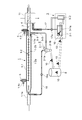
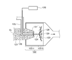
- the exhaust gas treatment apparatus for a marine diesel engine shown as the fourth embodiment of the present invention in FIG. 4 is a system for supplying a mixed flow of PM combustion exhaust gas and low concentration gas to the PM fleece clubber.
- the configuration is such that the flue gas recirculation pipe 12 from the PM incinerator 3-1 of the PM incinerator 3 of the first embodiment shown in FIG. It is made to project. That is, the configuration is similar to the first embodiment apparatus shown in FIG. 1 in the particulate matter contained in the exhaust gas of marine diesel engines that use low quality fuel such as heavy oil containing a high concentration of sulfur component as fuel.
- It has a discharge electrode 1-2 to be charged and a tubular collecting tube 1-1 that constitutes a dust collecting electrode for collecting the charged particulate matter, and separates the separated particulate material from the tubular collecting tube 1-1.
- Separately collecting cyclone type collecting means 2-1 for collecting, and the low concentration exhaust gas outlet pipe 4 of PM10 removes SOx contained in the exhaust gas by utilizing the difference in diffusion speed of gas and particles, but PM
- the PM fleece clubber 11 that removes almost all of the above is installed to remove SOx from the atmospheric exhaust gas, and the separate collection unit 2 provided downstream of the electric dust collection unit 1 in the flow direction of the exhaust gas, Separation Is constituted by a cyclone collecting means 2-1 as stage.
- the cyclone collecting means 2-1 is composed of a single tangential cyclone 2-1a connected to the high concentration exhaust gas deriving portion 1-1b of the collection pipe 1-1 through a communication pipe 5-1. Further, between the tangential cyclone 2-1a and the low concentration exhaust gas outlet pipe 4, the purified gas after passing through the tangential cyclone 2-1a is joined to the low concentration exhaust gas flowing in the low concentration exhaust gas outlet pipe 4.
- a discharge pipe 6-1 is provided, and the low-concentration exhaust gas outlet pipe 4 has a flow rate for adjusting the flow rate of the high-concentration exhaust gas flow rate and flow rate into the tangential cyclone 2-1a and the low-concentration exhaust gas discharge rate.
- a control damper 7 is provided.
- the PM incineration unit 3 provided for incinerating PM is controlled by the controller 3-2 with the incineration temperature, the intake air amount, the flow rate of the combustion exhaust gas, etc., and the electric heater 3-1a It consists of PM incinerator 3-1.
- a reflux pipe 15 is provided for returning the combustion exhaust gas from the PM incinerator 3-1 to the upstream side of the PM fleece scrubber 11 of the low concentration exhaust gas outlet pipe 4 of PM10.
- the reflux pipe 15 has its tip projecting into the low concentration exhaust gas outlet pipe 4.
- 15a is a blower that imparts kinetic energy to the exhaust gas flow flowing in the reflux pipe 15 as described above.
- the PM combustion exhaust gas containing a high concentration of sulfur components generated by incineration of PM 10 returns to the upstream side of the PM fleece scrubber 11 of the low concentration exhaust gas outlet pipe 4 through the reflux pipe 15 and is mixed with the PM low concentration exhaust gas. And supplied to the PM fleece clubber 11.
- the atmospheric exhaust gas becomes a gas in which the PM remains but the sulfur content is removed, and the atmospheric environment is preserved.
- the treated water of the PM fleece scrubber 11 contains a high concentration of sulfur components, but contains almost no PM, so it can be discharged to the ocean such as through a scrubber, and can be easily controlled with less man-hours and small size. Can be processed by a simple processing device.
- the exhaust gas treatment apparatus for a marine diesel engine shown as the fifth embodiment of the present invention in FIG. 5 is a system for supplying PM combustion exhaust gas directly to the PM fleece scrubber 11, and its configuration is high in concentration.
- Discharge electrode 1-2 for charging particulate matter contained in exhaust gas of marine diesel engine using low quality fuel such as heavy oil containing sulfur component as fuel, and dust collecting electrode for collecting charged particulate matter
- a cyclone-type separation / collection means 2-1 for separating and collecting particulate matter separated from the tubular collection tube 1-1, and further having a low concentration of PM10
- a PM fleece scrubber 11 that removes SOx contained in the exhaust gas but hardly removes PM is installed in the exhaust gas outlet pipe 4 by utilizing the difference in diffusion speed between gas and particles.
- the SOx is removed from the gas, and the separation / collection unit 2 provided on the downstream side of the electric dust collection unit 1 in the flow direction of the exhaust gas is constituted by a cyclone collection unit 2-1 as a separation unit.
- the cyclone collecting means 2-1 is a single tangential type connected to the high concentration exhaust gas deriving portion 1-1b of the collection pipe 1-1 through a communication pipe 5-1 and a high concentration exhaust gas pipe 5-2.
- the high-concentration exhaust gas flow which is composed of the cyclone 2-1a and is discharged from the high-concentration exhaust gas deriving unit 1-1b, is introduced into the tangential cyclone 2-1a to collect and process large-diameter particles and remove them with the same cyclone.
- the exhaust gas flow containing the fine particles that could not be produced is sent to the exhaust gas introduction pipe 1-1a via the reflux pipe 16 and refluxed.
- a blower 16 a imparts kinetic energy to the exhaust gas flow flowing in the reflux pipe 16.
- the PM incineration unit 3 provided for incineration of PM is controlled by the controller 3-2 in the same manner as described above, and the incineration temperature, the intake air amount, the flow rate of combustion exhaust gas, etc. are controlled, and the electric heater 3-1a is incorporated.
- PM incinerator 3-1 The apparatus of this embodiment is mainly characterized in that a reflux pipe 17 is provided for directly supplying the combustion exhaust gas from the PM incinerator 3-1 to the PM fleece scrubber 11 installed in the low concentration exhaust gas outlet pipe 4 of PM10. . 17a is a blower for imparting kinetic energy to the exhaust gas flow flowing in the reflux pipe 17, similar to the above.
- the PM low-concentration exhaust gas and the PM combustion exhaust gas supplied to the PM fleece scrubber 11 become a gas in which the PM remains but the sulfur content is removed, and the atmospheric environment is preserved.
- the treated water of the PM fleece scrubber 11 contains a high concentration of sulfur components, but contains almost no PM, so it can be discharged to the ocean such as through a scrubber, and can be easily controlled with less man-hours and small size. Can be processed by a simple processing device.
- corrosive PM combustion exhaust gas does not flow into the electric dust collection unit 1 and the separate collection unit 2, so members (collection tubes, electrodes, etc.) constituting them are not included. It is not necessary to use a highly corrosion resistant material, and it is inexpensive and easy to ensure durability.
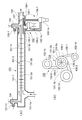
- the exhaust gas treatment apparatus for a marine diesel engine shown as a sixth embodiment apparatus of the present invention in FIG. 6 is provided with a plurality of stockers that also serve as PM incinerators in the second embodiment apparatus shown in FIG. It is configured so that collection and alternate combustion can be performed. That is, the configuration is similar to the second embodiment apparatus shown in FIG. 2 in the particulate matter contained in the exhaust gas of marine diesel engines that use low quality fuel such as heavy oil containing a high concentration of sulfur component as fuel. It has a discharge electrode 1-2 to be charged and a tubular collecting tube 1-1 that constitutes a dust collecting electrode for collecting the charged particulate matter, and separates the separated particulate material from the tubular collecting tube 1-1.
- Part 1-1b The high-concentration exhaust gas pipe 5-2 is provided with a cyclone collecting means composed of a tangential cyclone 2-1a similar to the above, and the high-concentration exhaust gas flow discharged from the high-concentration exhaust gas outlet 1-1b is tangentially connected.
- the large-diameter particles are collected and processed by being introduced into the cyclone 2-1a, and an exhaust gas stream containing fine particles that cannot be removed by the cyclone is introduced into the introduction pipe 1-1a via the reflux pipe 14-1. It is said to be a method of pumping and refluxing.
- the PM incineration unit 3 is provided with a multi-branch pipe 2-1e such as a bifurcated part having a built-in switching valve 2-1d in a hopper 2-1b immediately below the cone-shaped part at the bottom of the tangential cyclone 2-1a.
- the inner volume of the pipe 2-1e is lower than that of the hopper 2-1b, which also serves as a PM incinerator, through a shutter 2-1c that holds and drops the PM collected and accumulated in the hopper 2-1b.
- a large stocker 3'-1 is provided.
- the stocker 3'-1 also serving as a PM incinerator has a built-in electric heater 3'-1a, and the controller 3-2 controls the incineration temperature, the intake air amount, the flow rate of combustion exhaust gas, etc. It has become.
- the shutter 2-1c is opened and the stocker directly under the hopper PM is dropped into 3'-1, and then the shutter 2-1c is closed and stocked.
- Combustion exhaust gas from the stocker 3-1 that also serves as a PM incinerator is configured to be returned to the exhaust gas introduction pipe 1-1a of the electric dust collector 1 through a return pipe 14-2.
- the leading ends of the reflux pipes 14-1 and 14-2 are projected into the exhaust gas introduction pipe 1-1a in consideration of the ejector effect.
- the tip opening is bent so as to be directed in the exhaust gas outflow direction.
- the stocker 3'-1 which also serves as the PM incinerator may be an incinerator using a burner (not shown) instead of the electric heater 3'-1a.
Landscapes
- Engineering & Computer Science (AREA)
- Chemical & Material Sciences (AREA)
- Combustion & Propulsion (AREA)
- Mechanical Engineering (AREA)
- General Engineering & Computer Science (AREA)
- General Chemical & Material Sciences (AREA)
- Analytical Chemistry (AREA)
- Oil, Petroleum & Natural Gas (AREA)
- Chemical Kinetics & Catalysis (AREA)
- Processes For Solid Components From Exhaust (AREA)
- Exhaust Gas After Treatment (AREA)
- Electrostatic Separation (AREA)
- Chimneys And Flues (AREA)
- Treating Waste Gases (AREA)
- Separating Particles In Gases By Inertia (AREA)
Priority Applications (3)
| Application Number | Priority Date | Filing Date | Title |
|---|---|---|---|
| CN201580017389.3A CN106170610B (zh) | 2014-04-08 | 2015-04-08 | 使用含有高浓度硫成分的低质燃料的船舶用柴油发动机的排气处理装置 |
| EP15777369.8A EP3130773A4 (de) | 2014-04-08 | 2015-04-08 | Abgasreinigungsvorrichtung für einen schiffsdieselmotor mit minderwertigem brennstoff mit hohem schwefelgehalt |
| KR1020167031113A KR101828734B1 (ko) | 2014-04-08 | 2015-04-08 | 고농도로 황 성분을 함유하는 저질 연료를 사용하는 선박용 디젤 엔진의 배기가스 처리 장치 |
Applications Claiming Priority (2)
| Application Number | Priority Date | Filing Date | Title |
|---|---|---|---|
| JP2014079715A JP6238823B2 (ja) | 2014-04-08 | 2014-04-08 | 高濃度に硫黄成分を含有する低質燃料を使用する船舶用ディーゼルエンジンの排ガス処理装置 |
| JP2014-079715 | 2014-04-08 |
Publications (1)
| Publication Number | Publication Date |
|---|---|
| WO2015156320A1 true WO2015156320A1 (ja) | 2015-10-15 |
Family
ID=54287893
Family Applications (1)
| Application Number | Title | Priority Date | Filing Date |
|---|---|---|---|
| PCT/JP2015/060982 WO2015156320A1 (ja) | 2014-04-08 | 2015-04-08 | 高濃度に硫黄成分を含有する低質燃料を使用する船舶用ディーゼルエンジンの排ガス処理装置 |
Country Status (6)
| Country | Link |
|---|---|
| EP (1) | EP3130773A4 (de) |
| JP (1) | JP6238823B2 (de) |
| KR (1) | KR101828734B1 (de) |
| CN (1) | CN106170610B (de) |
| MA (1) | MA39858A (de) |
| WO (1) | WO2015156320A1 (de) |
Cited By (2)
| Publication number | Priority date | Publication date | Assignee | Title |
|---|---|---|---|---|
| CN113996150A (zh) * | 2021-11-03 | 2022-02-01 | 福建三宝钢铁有限公司 | 一种高效脱硫脱硝方法及系统 |
| JP7411025B1 (ja) | 2022-07-05 | 2024-01-10 | 株式会社新来島どっく | ドレン受けホッパー装置 |
Families Citing this family (16)
| Publication number | Priority date | Publication date | Assignee | Title |
|---|---|---|---|---|
| JP2016151196A (ja) * | 2015-02-16 | 2016-08-22 | 三菱重工業株式会社 | 排ガス再循環システム、およびこれを備えた舶用エンジン |
| JP6579150B2 (ja) * | 2017-04-25 | 2019-09-25 | トヨタ自動車株式会社 | 排ガス浄化装置 |
| US10696906B2 (en) | 2017-09-29 | 2020-06-30 | Marathon Petroleum Company Lp | Tower bottoms coke catching device |
| JP7144172B2 (ja) * | 2018-04-03 | 2022-09-29 | トリニティ工業株式会社 | 電界浄化装置及びワーク乾燥システム |
| JP2022524631A (ja) * | 2019-03-11 | 2022-05-09 | ユニバーシティ オブ サザン カリフォルニア | SOx及びNOxのプラズマベースの浄化のためのシステム及び方法 |
| US20220184551A1 (en) * | 2019-03-11 | 2022-06-16 | University Of Southern California | Systems and methods for plasma-based remediation |
| US11975316B2 (en) | 2019-05-09 | 2024-05-07 | Marathon Petroleum Company Lp | Methods and reforming systems for re-dispersing platinum on reforming catalyst |
| JP2020195954A (ja) * | 2019-05-31 | 2020-12-10 | 臼井国際産業株式会社 | 電気集塵装置 |
| KR102315711B1 (ko) * | 2019-08-08 | 2021-10-21 | 황종덕 | 배기가스 정화장치 |
| US11384301B2 (en) | 2020-02-19 | 2022-07-12 | Marathon Petroleum Company Lp | Low sulfur fuel oil blends for stability enhancement and associated methods |
| KR102422754B1 (ko) * | 2020-11-24 | 2022-07-20 | 한국기계연구원 | 엔진 배출 입자상 물질의 제거장치를 이용한 입자상 물질의 제거방법 |
| US11898109B2 (en) | 2021-02-25 | 2024-02-13 | Marathon Petroleum Company Lp | Assemblies and methods for enhancing control of hydrotreating and fluid catalytic cracking (FCC) processes using spectroscopic analyzers |
| US20220268694A1 (en) | 2021-02-25 | 2022-08-25 | Marathon Petroleum Company Lp | Methods and assemblies for determining and using standardized spectral responses for calibration of spectroscopic analyzers |
| US11905468B2 (en) | 2021-02-25 | 2024-02-20 | Marathon Petroleum Company Lp | Assemblies and methods for enhancing control of fluid catalytic cracking (FCC) processes using spectroscopic analyzers |
| US11692141B2 (en) | 2021-10-10 | 2023-07-04 | Marathon Petroleum Company Lp | Methods and systems for enhancing processing of hydrocarbons in a fluid catalytic cracking unit using a renewable additive |
| US11802257B2 (en) | 2022-01-31 | 2023-10-31 | Marathon Petroleum Company Lp | Systems and methods for reducing rendered fats pour point |
Citations (4)
| Publication number | Priority date | Publication date | Assignee | Title |
|---|---|---|---|---|
| JPH0521118U (ja) * | 1991-08-30 | 1993-03-19 | 株式会社明電舎 | デイーゼルエンジン用消煙装置 |
| JP2005533963A (ja) * | 2002-07-25 | 2005-11-10 | エイ. ケムメル,レファート | ディーゼルエンジン排気ガスの汚染物質を削減するシステム及び方法 |
| JP2012140928A (ja) * | 2010-12-16 | 2012-07-26 | Usui Kokusai Sangyo Kaisha Ltd | 重油以下の低質燃料を使用するディーゼルエンジンの排気ガス浄化装置 |
| JP2013238172A (ja) * | 2012-05-15 | 2013-11-28 | Usui Kokusai Sangyo Kaisha Ltd | 重油より低質な燃料を使用する船舶用ディーゼルエンジン排ガス処理装置 |
Family Cites Families (4)
| Publication number | Priority date | Publication date | Assignee | Title |
|---|---|---|---|---|
| JP2008127998A (ja) * | 2006-11-16 | 2008-06-05 | Mitsubishi Fuso Truck & Bus Corp | 内燃機関の排気浄化装置 |
| KR101335891B1 (ko) * | 2009-10-14 | 2013-12-02 | 우수이 고쿠사이 산교 가부시키가이샤 | 전기식 배기가스 처리 방법 및 전기식 배기가스 처리 장치 |
| JP5863087B2 (ja) * | 2010-11-16 | 2016-02-16 | 臼井国際産業株式会社 | 重油以下の低質燃料を使用する大排気量ディーゼルエンジン用排ガス処理装置 |
| JP2014055567A (ja) * | 2012-09-13 | 2014-03-27 | Kawasaki Heavy Ind Ltd | 排気ガス浄化装置及びこれを備える船舶機関システム |
-
2014
- 2014-04-08 JP JP2014079715A patent/JP6238823B2/ja not_active Expired - Fee Related
-
2015
- 2015-04-08 WO PCT/JP2015/060982 patent/WO2015156320A1/ja active Application Filing
- 2015-04-08 CN CN201580017389.3A patent/CN106170610B/zh not_active Expired - Fee Related
- 2015-04-08 EP EP15777369.8A patent/EP3130773A4/de not_active Withdrawn
- 2015-04-08 KR KR1020167031113A patent/KR101828734B1/ko active IP Right Grant
- 2015-04-08 MA MA039858A patent/MA39858A/fr unknown
Patent Citations (4)
| Publication number | Priority date | Publication date | Assignee | Title |
|---|---|---|---|---|
| JPH0521118U (ja) * | 1991-08-30 | 1993-03-19 | 株式会社明電舎 | デイーゼルエンジン用消煙装置 |
| JP2005533963A (ja) * | 2002-07-25 | 2005-11-10 | エイ. ケムメル,レファート | ディーゼルエンジン排気ガスの汚染物質を削減するシステム及び方法 |
| JP2012140928A (ja) * | 2010-12-16 | 2012-07-26 | Usui Kokusai Sangyo Kaisha Ltd | 重油以下の低質燃料を使用するディーゼルエンジンの排気ガス浄化装置 |
| JP2013238172A (ja) * | 2012-05-15 | 2013-11-28 | Usui Kokusai Sangyo Kaisha Ltd | 重油より低質な燃料を使用する船舶用ディーゼルエンジン排ガス処理装置 |
Non-Patent Citations (1)
| Title |
|---|
| See also references of EP3130773A4 * |
Cited By (3)
| Publication number | Priority date | Publication date | Assignee | Title |
|---|---|---|---|---|
| CN113996150A (zh) * | 2021-11-03 | 2022-02-01 | 福建三宝钢铁有限公司 | 一种高效脱硫脱硝方法及系统 |
| CN113996150B (zh) * | 2021-11-03 | 2022-07-15 | 福建三宝钢铁有限公司 | 一种高效脱硫脱硝方法及系统 |
| JP7411025B1 (ja) | 2022-07-05 | 2024-01-10 | 株式会社新来島どっく | ドレン受けホッパー装置 |
Also Published As
| Publication number | Publication date |
|---|---|
| KR20160135838A (ko) | 2016-11-28 |
| KR101828734B1 (ko) | 2018-03-29 |
| JP6238823B2 (ja) | 2017-11-29 |
| CN106170610A (zh) | 2016-11-30 |
| CN106170610B (zh) | 2019-08-13 |
| EP3130773A4 (de) | 2017-03-08 |
| EP3130773A1 (de) | 2017-02-15 |
| MA39858A (fr) | 2017-02-15 |
| JP2015200230A (ja) | 2015-11-12 |
Similar Documents
| Publication | Publication Date | Title |
|---|---|---|
| JP6238823B2 (ja) | 高濃度に硫黄成分を含有する低質燃料を使用する船舶用ディーゼルエンジンの排ガス処理装置 | |
| JP2015200230A5 (de) | ||
| JP6319794B2 (ja) | 高濃度に硫黄成分を含有する重油等の低質燃料を使用する船舶用ディーゼルエンジンの排気ガス浄化装置 | |
| KR101835259B1 (ko) | 고농도로 황 성분을 함유하는 저질 연료를 사용하는 선박용 디젤 엔진의 배기가스 정화 장치 | |
| JP6351183B2 (ja) | 高濃度に硫黄成分を含有する重油等の低質燃料を使用する船舶用ディーゼルエンジンの排気ガス浄化装置 | |
| JP6403355B2 (ja) | エンジン排気ガスから微粒子物質の煤、灰及び重金属を除去するための方法及びシステム | |
| JP6041418B2 (ja) | 重油以下の低質燃料を使用する大排気量船舶用ディーゼルエンジンの排気ガス浄化装置 | |
| JP2012140928A5 (de) | ||
| JP2015200215A5 (de) | ||
| JP5843701B2 (ja) | 廃水処理装置、排気再循環ユニット、エンジンシステム、及び船舶 | |
| KR102482802B1 (ko) | 엔진 배기가스 또는 공정 장치로부터 미립자 물질의 제거를 위한 방법 및 시스템 | |
| JP5889229B2 (ja) | 再循環排ガス浄化装置及び再循環排ガス浄化方法 | |
| KR102067385B1 (ko) | 디젤엔진용 매연 저감장치 및 저감방법 | |
| KR102155942B1 (ko) | 세정액의 배출을 방지하기 위한 데미스터를 구비하는 스크러버 | |
| KR102315711B1 (ko) | 배기가스 정화장치 | |
| JP2005113817A (ja) | ディーゼルエンジンの排気ガス浄化装置 | |
| EP3501623A1 (de) | Kompaktwäscher und verfahren dafür | |
| Hagström et al. | EffShip |
Legal Events
| Date | Code | Title | Description |
|---|---|---|---|
| 121 | Ep: the epo has been informed by wipo that ep was designated in this application |
Ref document number: 15777369 Country of ref document: EP Kind code of ref document: A1 |
|
| DPE1 | Request for preliminary examination filed after expiration of 19th month from priority date (pct application filed from 20040101) | ||
| NENP | Non-entry into the national phase |
Ref country code: DE |
|
| REEP | Request for entry into the european phase |
Ref document number: 2015777369 Country of ref document: EP |
|
| WWE | Wipo information: entry into national phase |
Ref document number: 2015777369 Country of ref document: EP |
|
| ENP | Entry into the national phase |
Ref document number: 20167031113 Country of ref document: KR Kind code of ref document: A |