EP3130773A1 - Abgasreinigungsvorrichtung für einen schiffsdieselmotor mit minderwertigem brennstoff mit hohem schwefelgehalt - Google Patents
Abgasreinigungsvorrichtung für einen schiffsdieselmotor mit minderwertigem brennstoff mit hohem schwefelgehalt Download PDFInfo
- Publication number
- EP3130773A1 EP3130773A1 EP15777369.8A EP15777369A EP3130773A1 EP 3130773 A1 EP3130773 A1 EP 3130773A1 EP 15777369 A EP15777369 A EP 15777369A EP 3130773 A1 EP3130773 A1 EP 3130773A1
- Authority
- EP
- European Patent Office
- Prior art keywords
- exhaust gas
- pipe
- concentration
- low
- precipitation
- Prior art date
- Legal status (The legal status is an assumption and is not a legal conclusion. Google has not performed a legal analysis and makes no representation as to the accuracy of the status listed.)
- Withdrawn
Links
Images


Classifications
-
- F—MECHANICAL ENGINEERING; LIGHTING; HEATING; WEAPONS; BLASTING
- F01—MACHINES OR ENGINES IN GENERAL; ENGINE PLANTS IN GENERAL; STEAM ENGINES
- F01N—GAS-FLOW SILENCERS OR EXHAUST APPARATUS FOR MACHINES OR ENGINES IN GENERAL; GAS-FLOW SILENCERS OR EXHAUST APPARATUS FOR INTERNAL COMBUSTION ENGINES
- F01N3/00—Exhaust or silencing apparatus having means for purifying, rendering innocuous, or otherwise treating exhaust
- F01N3/02—Exhaust or silencing apparatus having means for purifying, rendering innocuous, or otherwise treating exhaust for cooling, or for removing solid constituents of, exhaust
- F01N3/037—Exhaust or silencing apparatus having means for purifying, rendering innocuous, or otherwise treating exhaust for cooling, or for removing solid constituents of, exhaust by means of inertial or centrifugal separators, e.g. of cyclone type, optionally combined or associated with agglomerators
-
- B—PERFORMING OPERATIONS; TRANSPORTING
- B01—PHYSICAL OR CHEMICAL PROCESSES OR APPARATUS IN GENERAL
- B01D—SEPARATION
- B01D53/00—Separation of gases or vapours; Recovering vapours of volatile solvents from gases; Chemical or biological purification of waste gases, e.g. engine exhaust gases, smoke, fumes, flue gases, aerosols
- B01D53/32—Separation of gases or vapours; Recovering vapours of volatile solvents from gases; Chemical or biological purification of waste gases, e.g. engine exhaust gases, smoke, fumes, flue gases, aerosols by electrical effects other than those provided for in group B01D61/00
- B01D53/323—Separation of gases or vapours; Recovering vapours of volatile solvents from gases; Chemical or biological purification of waste gases, e.g. engine exhaust gases, smoke, fumes, flue gases, aerosols by electrical effects other than those provided for in group B01D61/00 by electrostatic effects or by high-voltage electric fields
-
- B—PERFORMING OPERATIONS; TRANSPORTING
- B03—SEPARATION OF SOLID MATERIALS USING LIQUIDS OR USING PNEUMATIC TABLES OR JIGS; MAGNETIC OR ELECTROSTATIC SEPARATION OF SOLID MATERIALS FROM SOLID MATERIALS OR FLUIDS; SEPARATION BY HIGH-VOLTAGE ELECTRIC FIELDS
- B03C—MAGNETIC OR ELECTROSTATIC SEPARATION OF SOLID MATERIALS FROM SOLID MATERIALS OR FLUIDS; SEPARATION BY HIGH-VOLTAGE ELECTRIC FIELDS
- B03C3/00—Separating dispersed particles from gases or vapour, e.g. air, by electrostatic effect
- B03C3/017—Combinations of electrostatic separation with other processes, not otherwise provided for
-
- B—PERFORMING OPERATIONS; TRANSPORTING
- B03—SEPARATION OF SOLID MATERIALS USING LIQUIDS OR USING PNEUMATIC TABLES OR JIGS; MAGNETIC OR ELECTROSTATIC SEPARATION OF SOLID MATERIALS FROM SOLID MATERIALS OR FLUIDS; SEPARATION BY HIGH-VOLTAGE ELECTRIC FIELDS
- B03C—MAGNETIC OR ELECTROSTATIC SEPARATION OF SOLID MATERIALS FROM SOLID MATERIALS OR FLUIDS; SEPARATION BY HIGH-VOLTAGE ELECTRIC FIELDS
- B03C3/00—Separating dispersed particles from gases or vapour, e.g. air, by electrostatic effect
- B03C3/34—Constructional details or accessories or operation thereof
- B03C3/40—Electrode constructions
- B03C3/41—Ionising-electrodes
-
- B—PERFORMING OPERATIONS; TRANSPORTING
- B03—SEPARATION OF SOLID MATERIALS USING LIQUIDS OR USING PNEUMATIC TABLES OR JIGS; MAGNETIC OR ELECTROSTATIC SEPARATION OF SOLID MATERIALS FROM SOLID MATERIALS OR FLUIDS; SEPARATION BY HIGH-VOLTAGE ELECTRIC FIELDS
- B03C—MAGNETIC OR ELECTROSTATIC SEPARATION OF SOLID MATERIALS FROM SOLID MATERIALS OR FLUIDS; SEPARATION BY HIGH-VOLTAGE ELECTRIC FIELDS
- B03C3/00—Separating dispersed particles from gases or vapour, e.g. air, by electrostatic effect
- B03C3/34—Constructional details or accessories or operation thereof
- B03C3/40—Electrode constructions
- B03C3/45—Collecting-electrodes
- B03C3/49—Collecting-electrodes tubular
-
- F—MECHANICAL ENGINEERING; LIGHTING; HEATING; WEAPONS; BLASTING
- F01—MACHINES OR ENGINES IN GENERAL; ENGINE PLANTS IN GENERAL; STEAM ENGINES
- F01N—GAS-FLOW SILENCERS OR EXHAUST APPARATUS FOR MACHINES OR ENGINES IN GENERAL; GAS-FLOW SILENCERS OR EXHAUST APPARATUS FOR INTERNAL COMBUSTION ENGINES
- F01N3/00—Exhaust or silencing apparatus having means for purifying, rendering innocuous, or otherwise treating exhaust
- F01N3/01—Exhaust or silencing apparatus having means for purifying, rendering innocuous, or otherwise treating exhaust by means of electric or electrostatic separators
-
- F—MECHANICAL ENGINEERING; LIGHTING; HEATING; WEAPONS; BLASTING
- F01—MACHINES OR ENGINES IN GENERAL; ENGINE PLANTS IN GENERAL; STEAM ENGINES
- F01N—GAS-FLOW SILENCERS OR EXHAUST APPARATUS FOR MACHINES OR ENGINES IN GENERAL; GAS-FLOW SILENCERS OR EXHAUST APPARATUS FOR INTERNAL COMBUSTION ENGINES
- F01N3/00—Exhaust or silencing apparatus having means for purifying, rendering innocuous, or otherwise treating exhaust
- F01N3/02—Exhaust or silencing apparatus having means for purifying, rendering innocuous, or otherwise treating exhaust for cooling, or for removing solid constituents of, exhaust
-
- B—PERFORMING OPERATIONS; TRANSPORTING
- B01—PHYSICAL OR CHEMICAL PROCESSES OR APPARATUS IN GENERAL
- B01D—SEPARATION
- B01D2257/00—Components to be removed
- B01D2257/30—Sulfur compounds
- B01D2257/302—Sulfur oxides
-
- B—PERFORMING OPERATIONS; TRANSPORTING
- B01—PHYSICAL OR CHEMICAL PROCESSES OR APPARATUS IN GENERAL
- B01D—SEPARATION
- B01D2258/00—Sources of waste gases
- B01D2258/01—Engine exhaust gases
- B01D2258/012—Diesel engines and lean burn gasoline engines
-
- B—PERFORMING OPERATIONS; TRANSPORTING
- B01—PHYSICAL OR CHEMICAL PROCESSES OR APPARATUS IN GENERAL
- B01D—SEPARATION
- B01D2259/00—Type of treatment
- B01D2259/45—Gas separation or purification devices adapted for specific applications
- B01D2259/4566—Gas separation or purification devices adapted for specific applications for use in transportation means
-
- B—PERFORMING OPERATIONS; TRANSPORTING
- B03—SEPARATION OF SOLID MATERIALS USING LIQUIDS OR USING PNEUMATIC TABLES OR JIGS; MAGNETIC OR ELECTROSTATIC SEPARATION OF SOLID MATERIALS FROM SOLID MATERIALS OR FLUIDS; SEPARATION BY HIGH-VOLTAGE ELECTRIC FIELDS
- B03C—MAGNETIC OR ELECTROSTATIC SEPARATION OF SOLID MATERIALS FROM SOLID MATERIALS OR FLUIDS; SEPARATION BY HIGH-VOLTAGE ELECTRIC FIELDS
- B03C2201/00—Details of magnetic or electrostatic separation
- B03C2201/10—Ionising electrode has multiple serrated ends or parts
-
- B—PERFORMING OPERATIONS; TRANSPORTING
- B03—SEPARATION OF SOLID MATERIALS USING LIQUIDS OR USING PNEUMATIC TABLES OR JIGS; MAGNETIC OR ELECTROSTATIC SEPARATION OF SOLID MATERIALS FROM SOLID MATERIALS OR FLUIDS; SEPARATION BY HIGH-VOLTAGE ELECTRIC FIELDS
- B03C—MAGNETIC OR ELECTROSTATIC SEPARATION OF SOLID MATERIALS FROM SOLID MATERIALS OR FLUIDS; SEPARATION BY HIGH-VOLTAGE ELECTRIC FIELDS
- B03C2201/00—Details of magnetic or electrostatic separation
- B03C2201/30—Details of magnetic or electrostatic separation for use in or with vehicles
-
- F—MECHANICAL ENGINEERING; LIGHTING; HEATING; WEAPONS; BLASTING
- F01—MACHINES OR ENGINES IN GENERAL; ENGINE PLANTS IN GENERAL; STEAM ENGINES
- F01N—GAS-FLOW SILENCERS OR EXHAUST APPARATUS FOR MACHINES OR ENGINES IN GENERAL; GAS-FLOW SILENCERS OR EXHAUST APPARATUS FOR INTERNAL COMBUSTION ENGINES
- F01N2590/00—Exhaust or silencing apparatus adapted to particular use, e.g. for military applications, airplanes, submarines
- F01N2590/02—Exhaust or silencing apparatus adapted to particular use, e.g. for military applications, airplanes, submarines for marine vessels or naval applications
-
- Y—GENERAL TAGGING OF NEW TECHNOLOGICAL DEVELOPMENTS; GENERAL TAGGING OF CROSS-SECTIONAL TECHNOLOGIES SPANNING OVER SEVERAL SECTIONS OF THE IPC; TECHNICAL SUBJECTS COVERED BY FORMER USPC CROSS-REFERENCE ART COLLECTIONS [XRACs] AND DIGESTS
- Y02—TECHNOLOGIES OR APPLICATIONS FOR MITIGATION OR ADAPTATION AGAINST CLIMATE CHANGE
- Y02T—CLIMATE CHANGE MITIGATION TECHNOLOGIES RELATED TO TRANSPORTATION
- Y02T10/00—Road transport of goods or passengers
- Y02T10/10—Internal combustion engine [ICE] based vehicles
- Y02T10/12—Improving ICE efficiencies
Definitions
- the present invention relates to an exhaust gas treatment technique for a large-displacement marine diesel engine using low-quality fuel such as fuel oil particularly containing high-concentration sulfur components
- fuel oil particularly containing high-concentration sulfur components
- fuel oil is represented as Diesel Oil (DO), Marine Diesel Fuel (MDF) or Marine Diesel Oil (MDO), Marine Fuel Oil (MFO), Heavy Fuel Oil (HFO), and Residual Fuel Oil (RFO) in ship industries
- DO Diesel Oil
- MDF Marine Diesel Fuel
- MDO Marine Fuel Oil
- MFO Marine Fuel Oil
- HFO Heavy Fuel Oil
- RFO Residual Fuel Oil
- the present invention relates to an exhaust gas treatment equipment in a large-displacement marine diesel engine that discharges high-temperature exhaust gas in which PM is collected from exhaust gas so as to allow the engine to be driven continuously for a long period of time and to voyage continuously, and a device for burning the collected PM inside the ship is disposed.
- PM Particulate matter mainly including carbon, sulfur oxides (hereinafter referred to as “SOx”) and nitrogen oxides (hereinafter referred to as “NOx”) contained in exhaust gas discharged from the diesel engines not only cause air pollution as well known but also are substances extremely hazardous to human bodies. Therefore, purification of the exhaust gas is extremely important.
- SOx sulfur oxides
- NOx nitrogen oxides
- PM (particulate matter) components in exhaust gas of a diesel engine are classified into two, that is, soluble organic fractions (hereinafter referred to as "SOF") and insoluble organic fractions (hereinafter referred to as "ISF").
- SOF components are mainly composed of unburned ones of fuel and lubricant oil, including harmful substances such as carcinogenic polycyclic aromatics.
- ISF components are mainly composed of low-electrical-resistivity carbon (soot) and sulfate components. Due to influences of these SOF components and ISF components on human bodies and environments, exhaust gas is desired to be reduced as much as possible. In particular, the degree of adverse effects of PM on living bodies are particularly problematic when the particle diameter is of a nanometer size.
- Patent Literatures 1, 2 and 3 As the electrical treatment method using corona discharge, for example, a method and device described below (Patent Literatures 1, 2 and 3) have been proposed.
- Patent Literature 1 as schematically described in Figure 7 , the Applicant has suggested an electrical treatment device for exhaust gas of a diesel engine, wherein a discharging/charging unit 122 formed of a corona discharging unit 122-1 and a charging unit 122-2 is installed on an exhaust gas passage 121 to charge PM 128 mainly composed of carbon in exhaust gas G1 with corona-discharged electrons 129, and the charged PM 128 is collected by a collection plate 123 disposed in the exhaust gas passage 121, the device having the configuration is such that an electrode needle 124 in the discharging/charging unit 122 has a short length in a flowing direction of an exhaust gas flow, and the collection plate 123 is disposed in a direction perpendicular to the flowing direction of the exhaust gas flow.
- the reference numeral 125 denotes a seal gas pipe
- 126 denotes a high-voltage power supply device
- 127 denotes an exhaust gas induction pipe.
- Patent Literature 2 as schematically shown in Figure 8(A) , the Applicant has preliminarily suggested an electrical treatment device for exhaust gas of a diesel engine in which the cyclone collection means 132-1 is constituted by two tangent-type cyclones 132-1a.
- This device is configured such that to a PM-high-concentration exhaust gas delivery unit 131-1b of a collection pipe 131-1, two tangent-type cyclones 132-1a are connected in parallel with each other through communication pipes 135-1 and 135-2 to form a cyclone collection means 132-1, and discharge pipes 136-1 and 136-2 for use in allowing purified gas after passing through the respective tangent-type cyclones 132-1a to join to a PM-low-concentration exhaust gas flowing through a PM-low-concentration exhaust gas delivery pipe 133 are also formed.
- the electrical treatment device for exhaust gas is mainly classified into the tubular collection unit 131 forming electric precipitation means and the separating and collecting unit 132 forming separating and collecting means, and the tubular collection unit 131 for collecting PM particles is provided with a collection pipe 131-1 having a collection wall surface 131-K with a predetermined length and forming a precipitation electrode and an discharge electrode 131-2 for charging PM contained in exhaust gas.
- the collection pipe 131-1 forming the precipitation electrode is provided with an exhaust gas introduction inlet 131-1a on the tip of the upstream side (diesel engine side), a PM-low-concentration exhaust gas delivery pipe 133 near a shaft center on the downstream side and a PM-high-concentration exhaust gas delivery unit 131b near the inner peripheral surface of the end on the downstream side, which are respectively installed side by side.
- the discharge electrode 131-2 is provided with a main electrode 131-2a that extends over the entire length of the collection pipe 131-1 forming the precipitation electrode, and a group of electrode needles 131-2b that protrude radially and are disposed on the main electrode with predetermined intervals.
- the discharge electrode 131-2 constituted in this manner has its two ends of the main electrode 131-2a supported by support members 134 vertically installed on a seal air introduction pipe unit 131-1c formed on the exhaust gas introduction inlet 131-1a side of collection pipe 131-1 and a seal air introduction pipe unit 131-1 formed on the inlet portion of the PM-low-concentration exhaust gas delivery pipe 133.
- Reference numeral 137 represents a flow-rate control damper.
- Patent Literature 3 as schematically shown in Figure 9 , the Applicant has preliminarily suggested an exhaust gas treatment equipment for a diesel engine of a recirculation system using cyclones.
- This device relates to an exhaust gas treatment equipment for a marine diesel engine provided with an discharge electrode 141-2 for charging particulate matter contained in exhaust gas of a marine diesel engine using a fuel having a lower quality than fuel oil, and a tubular collection unit 141-1 forming a precipitation electrode for collecting the particulate matter charged, and a separating and collecting means of a cyclone system for selectively collecting the particulate matter separated from the tubular collection unit 141-1, and in a pipe from a PM-high-concentration exhaust gas delivery unit 141-1b for the particulate matter formed near the inner peripheral surface on the downstream side of the tubular collection unit 141-1, a cyclone collection means 142-1 constituted by a tangent-type cyclone 142-1a is formed, and in this system, by introducing a PM-high-concentr
- reference numeral 141-1a represents the exhaust gas introduction inlet
- 141-1c and 143-1 represent seal air introduction pipe units
- 141-2a represents the main electrode
- 141-2b represents the electrode needle
- 143 represents the PM-low-concentration exhaust gas delivery pipe
- 144 represents the support member of the main electrode
- 148 represents the flow rate control dumper.
- Non-Patent Literature 1 in Chapter 3 "Requirements for machinery spaces of all ships", Part C "Control of discharge of oil", Regulation 15 "Control of discharge of oil", A. "Discharges outside special sea areas", .2 "Any discharge into the sea of oil or oily mixtures from ships of 400 gross tonnage and above shall be prohibited except when all the following conditions are satisfied", it is defined in .3 that "the oil content of the oily mixture without dilution does not exceed 15 parts per million".
- B the oil content of the oily mixture without dilution does not exceed 15 parts per million.
- oil refers to crude oil, fuel oil, and lubricant
- oil mixtures refers to mixtures containing oil
- Non-Patent Literature 2 by recirculating EGR gas diverted from exhaust gas to intake air, it is possible to reduce NO x by 80% from the exhaust gas and remove SO x nearly 100% from the EGR gas.
- Non-Patent Literature 3 has introduced a technology, as an example of SO x -compliant technology using a two-stroke engine made by MAN B&W with an output of 21,000 kW equipped on Ficaria Seaways of Demark by Alfa Laval, in which, by a treatment by a scrubber for exhaust gas using seawater or fresh water depending on the situation while fuel oil with a sulfur content of 2.2 percent is being used, cleaning and removal are performed to a level at the time of using fuel oil with a sulfur content of 0.1 percent in exhaust gas, which is a required level scheduled to come into force in 2015 by IMO (International Maritime Organization).
- IMO International Maritime Organization
- Patent Literature 1 for example, an electrical treatment device for exhaust gas of a diesel engine depicted in Figure 9 .
- a complicated device which is constituted by a tangent-type cyclone 132-1a depicted in Figure 8(A) , or as depicted in Figure 8(B) , a plurality of tangent-type cyclones having different treatment capabilities, such as, for example, a tangent-type cyclone 132-1b having a small treatment capability, a tangent-type cyclone 132-1c having a middle treatment capability and a tangent-type cyclone 132-1d having a large treatment capability of three kinds of cyclones, is used.
- reference numerals, 138-1, 138-2 and 138-3 represent communication pipes, and 139-1, 139-2 and 139-3 represent flow-rate control dumpers, respectively.
- no treatment unit has been disclosed so as to deal with a large amount of collected PM to be expected by continuously driving the engine and the exhaust gas treatment equipment.
- Non-Patent Literature 1 discharge regulations outside special sea areas, that is, prohibitions of discharge into the ocean of oil or oily mixtures are defined, or regulations on oil concentration or the like of oily mixtures without dilution are defined, and these are applied in the same manner to the substance that contains PM.
- Non-Patent Literature 2 by recirculating EGR gas diverted from exhaust gas to intake air, it is possible to reduce NO x by 80% from the exhaust gas and remove SO x nearly 100% from the EGR gas.
- the influence of soot and dust passing through the scrubber and sulfur components still contained in PM on the diesel machine body and the system it is required not only to perform an actual ship test for a long period of time but also to prevent wash water discharged outboard from the scrubber from influencing the environment and ecosystem.
- this wash water of the scrubber waste water treatment is expected to become a large problem, such as removal of environmental pollution components or ecosystem influential components and pH adjustment, together with dissolution and floating of PM, dissolution of SO 2 , and so forth. That is, even if PM is removed from the ERG gas, no PM is removed from the exhaust gas, and no technical idea for treating the collected PM can be seen.
- Bilge water overboard limit is 15 ppm.
- Non-Patent Literature 3 no PM is collected at all in the sea water mode (on line 16 in the fourth column to line 1 in the fifth column on page 12).
- the SCR scheme using catalytic reaction has been generally known.
- this SCR scheme in the state in which the temperature of exhaust gas of the engine is sufficiently high, if the catalyst is activated, and if the surface of the catalyst is reliably exposed without being covered with soot or the like, the catalyst functions normally and a high degree of NO x reduction can be achieved.
- a low-speed engine with a long stroke is in the mainstream, compared with an automobile engine or the like, in order to ensure an improvement in specific fuel consumption.
- the present invention is to provide a technology by which PM in exhaust gas of a large-displacement marine diesel engine which particularly uses low-quality fuel such as fuel oil containing high-concentration sulfur components and from which high-speed and/or large-flow-rate exhaust gas is discharged, is collected by using ESP/C/PDF and the collected PM is burned and treated inside the ship.
- An exhaust gas treatment equipment for a marine diesel engine using low-quality fuel such as fuel oil containing high-concentration sulfur components in accordance with the present invention includes: an electric precipitation means having a tubular collection unit with a predetermined length, the tubular collection unit being composed of a discharge electrode for charging particulate matters contained in exhaust gas from the engine and a precipitation electrode for collecting the particulate matters charged, the discharge electrode having a main electrode disposed inside the tubular collection unit in a pipe axial direction and a plurality of electrodes that radially protrude and are disposed on the main electrode with predetermined intervals; a PM-low-concentration exhaust gas delivery pipe and a PM-high concentration exhaust gas delivery pipe; a PM-free scrubber provided on the PM-low-concentration exhaust gas delivery pipe; a precipitation means for separating and collecting particulate matters detached from the tubular collection unit by using a cyclone for precipitation; a burning device for burning PM precipitated by the precipitation means; and a recirculation pipe for recirculating combustion exhaust
- the device of the present invention is preferably provided with modes in which the recirculation pipe is disposed so as to recirculate combustion exhaust gas from the burning device to the upstream of the PM-free scrubber provided on the PM-low-concentration exhaust gas delivery pipe, and the recirculation pipe from the cyclone for precipitation and the PM combustion exhaust gas recirculation pipe are connected with each other, a lower portion of the cyclone for precipitation is formed as a PM storing stocker, and the PM burning device is integrally formed on the lower portion of the stocker with a shutter interposed therebetween.
- the device of the present invention preferably has modes in which a plurality of the stockers are used to be controlled so as to start a burning process of PM after the ship has proceeded to a sea area in which gas and scrubber treatment water can be discharged, and a selective shutter is attached to the burning device so as to successively carry out burning processes by opening/closing the shutter with time differences.
- the burning device preferably has a function in which by controlling temperature-raising and heating processes of a built-in heating-use heater (electric heater or the like) or a burner by a controller so that PM is burned.
- An exhaust gas treatment equipment for a marine diesel engine using low-quality fuel such as fuel oil containing high-concentration sulfur components according to the present invention has the following functions and effects.
- PM in exhaust gas from a large-displacement marine diesel engine which particularly uses low-quality fuel such as fuel oil containing high-concentration sulfur components and from which high-speed and/or large-flow-rate exhaust gas is discharged is collected by an ESP/C/PDF and by burning the collected PM inside the ship, it becomes unnecessary to store all the PM collected by the cyclone inside the ship until the ship has arrived at a port having a PM treatment facility as a port facility so that a large space for the storage is not required inside the ship, the number of ship cabins is not reduced and cargoes are not reduced; therefore, it is possible to suppress an increase in costs, or preferably, a combustion exhaust gas generated at the time of burning is recirculated to the collection pipe, and charging, adhering, coagulating and condensing processes are again carried out so that the PM is positively collected, and by carrying out a scrubber treatment on a low-concentration discharged gas by a PM-free scrubber, SO x can be positively removed from an exhaust gas to be discharged
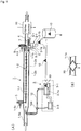
- An exhaust gas treatment equipment for a marine diesel engine shown in Figures 1 (A) and 1 (B) as the device of the first example of the present invention is mainly classified to an electric precipitation unit 1, a separating and collecting unit 2 and a PM burning unit 3.
- the electric precipitation unit 1 to be installed for collecting PM particles is provided with a collection pipe 1-1 having a predetermined length and configuring a precipitation electrode, and a discharge electrode 1-2 for charging PM contained in exhaust gas.
- the collection pipe 1-1 configuring the precipitation electrode is provided with an exhaust gas introduction pipe 1-1a on the end portion on the upstream side thereof (on diesel engine side), with a PM-low-concentration exhaust gas delivery pipe 4 attached near the shaft center on the end portion on the downstream side thereof and a PM-high-concentration exhaust gas delivery pipe 1-1b attached to the inner peripheral surface of the end portion on the downstream side thereof being formed so as to be placed side by side.
- the discharge electrode 1-2 is constituted by a main electrode 1-2a that extends over substantially the entire length of the vicinity of the shaft center of the collection pipe 1-1 and a group of electrode needles 1-2b that protrudes radially and are disposed with predetermined intervals in the longitudinal direction of the main electrode 1-2a.
- the discharge electrode 1-2 configured in this manner has two ends of its main electrode 1-2a supported by support members 5 that are vertically formed on a seal air introduction pipe unit 1-1c formed on the exhaust gas introduction pipe 1-1a side of the collection pipe 1-1 and a seal air introduction pipe unit 4-1 formed on the inlet portion of the PM-low-concentration exhaust gas delivery pipe 4. Moreover, in the PM-low-concentration exhaust gas delivery pipe 4 for PM 10, by installing a PM-free scrubber 11 that removes SO x contained in exhaust gas, but hardly removes any PM by utilizing difference in diffusion speeds between gas and particles, SO x is removed from an exhaust gas to be discharged to the atmosphere.
- the discharge electrode 1-2 is supported by stays (not shown) insulated from the inside of the collection pipe 1-1, if necessary, with predetermined intervals. Furthermore, the discharge electrode 1-2 is wired to a high-voltage power supply device (not shown) installed outside, and supplied with controlled high-voltage power.
- the separating and collecting unit 2 formed on the downstream side of the electric precipitation unit 1 in the flowing direction of the exhaust gas is constituted by cyclone collection means 2-1 serving as separation means.
- This cyclone collection means 2-1 is constituted by a single tangent-type cyclone 2-1a connected to the PM-high-concentration exhaust gas delivery unit 1-1b the collection pipe 1-1 through a communication pipe 5-1, and between the tangent-type cyclone 2-1a and the PM-low-concentration exhaust gas delivery pipe 4, an exhaust pipe 6-1 for allowing a purified gas after passing through the tangent-type cyclone 2-1a to join into a PM-low-concentration exhaust gas flowing inside the PM-low-concentration exhaust gas delivery pipe 4 is disposed.
- a flow rate control dumper 7 for carrying out flow-rate adjustments on PM-high-concentration exhaust gas inflow rate and inflow speed into the tangent-type cyclone 2-1a and a PM-low-concentration exhaust gas discharge amount is installed.
- PM 10 precipitated by the tangent-type cyclone 2-1a is accumulated inside a detachable hopper 2-1b installed right below a cone-shaped portion on a lower portion of the tangent-type cyclone 2-1a and when a hopper capacity limit has been reached, the hopper is exchanged to new one and stored therein.
- reference numeral 8 represents a stocker for storing the PM 10.
- a PM burning unit 3 to be installed to burn PM is controlled by a controller 3-2 in its burning temperature, flow rate, or the like of the exhaust gas, etc., and is constituted by a PM incinerator 3-1 having a built-in electric heater 3-1a.
- reference numeral 12a represents a blower for applying kinetic energy to exhaust gas flow flowing inside the recirculation pipe 12.
- the tip end of the recirculation pipe 12 is allowed to protrude into the exhaust gas introduction pipe 1-1a by taking an ejector effect into consideration, and the opening of the tip end is also bent to be directed to the exhaust gas outflow direction.
- the PM incinerator 3-1 may be an incinerator using a burner (not shown) in place of the electric heater 3-1a.
- a PM combustion exhaust gas containing high-concentration sulfur components generated upon burning the PM 10 is recirculated into the collection pipe 1-1 through the recirculation pipe 12 to be mixed with exhaust gas, and the mixed gas containing a high concentration of PM is led out to the tangent-type cyclone 2-1a so that an exhaust gas to be discharged to the atmosphere containing a high-concentration of sulfur components, but having a low-concentration of PM 10 is supplied to the PM-free scrubber 11.
- the exhaust gas to be discharged to the atmosphere is formed into a gas in which the sulfur components are removed although the PM remains therein so that the atmospheric environment can be preserved.
- the treatment water from the PM-free scrubber 11 contains high-concentration sulfur components, but contains hardly any PM, the discharge into the ocean such as a scrubber through operation is possible, and the treatment can be carried out by using a small-sized treatment device with a small number of processes which is easily controlled.
- an exhaust gas cooler 20 is installed in an exhaust gas introduction pipe 1-1a as shown in Figure 1(B) so that a PM combustion exhaust gas may be recirculated onto the downstream side of the exhaust gas cooler 20.
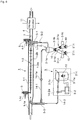
- An exhaust gas treatment equipment for a marine diesel engine shown in Figure 2 as a device of a second example of the present invention has a configuration in which the diesel engine exhaust gas treatment equipment of a recirculation system that uses the cyclone of the device of the first example shown in Figure 1 and a PM burning device are combined with each other, and is provided with an discharge electrode 1-2 for charging particulate matters contained in exhaust gas of a marine diesel engine using low-quality fuel such as fuel oil or the like containing high-concentration sulfur components as its fuel, a tubular collection pipe 1-1 forming a precipitation electrode for collecting the charged particulate matters and separating and collecting means 2-1 of a cyclone system for separating and collecting the particulate matters separated from the tubular collection pipe 1-1, and the marine diesel engine exhaust gas treatment equipment is designed such that by installing a PM-free scrubber 11 that removes SO x contained in exhaust gas, but hardly removes any PM by utilizing difference in diffusion speeds between gas and particles in a PM-low-concentration exhaust gas delivery pipe 4 for PM 10,
- the PM burning device is designed such that a hopper 2-1b is installed right below a corn-shaped portion right below the lower portion of the tangent-type cyclone 2-1a, and right below the hopper, a stocker 3'-1 that has an inner capacity larger than that of the hopper 2-1b and also serves as the PM incinerator, with a shutter 2-1c that holds PM precipitated and accumulated in the hopper and also allows the PM to drop down into the hopper being interposed therebetween.
- the stocker 3'-1 also serving as the PM incinerator is designed to have a built-in electric heater 3'-1a and control the burning temperature, the flow rate, etc. of the exhaust gas by the controller 3-2.
- the shutter 2-1c is opened to allow the PM to drop down the PM inside the stocker 3'-1 right below the hopper, and the shutter 2-1c is then closed to stock.
- a combustion exhaust gas from the stocker 3'-1 also serving as the PM incinerator is designed to be recirculated into the exhaust gas introduction pipe 1-1a of the electric precipitation unit 1 through the recirculation pipe 14-2.
- the tip ends of the recirculation pipes 14-1 and 14-2 are also allowed to protrude into the exhaust gas introduction pipe 1-1a by taking an ejector effect into consideration in the same manner as in the aforementioned example, with the tip end openings being bent to be directed in the exhaust gas outflow direction.
- Reference numerals 14-1a and 14-2a respectively represent blowers for applying kinetic energy to exhaust gas flows respectively flowing through the recirculation pipes 14-1 and 14-2. Additionally, it is needless to say that in place of the electric heater 3'-1a, a burner (not shown) may be used.
- a PM-high-concentration exhaust gas flow that has passed near an inner wall of the collection pipe is introduced to the tangent-type cyclone 2-1a through the communication pipe 5-1 and the PM-high-concentration exhaust gas pipe 5-2 by the PM-high-concentration exhaust gas introduction unit 1-1b of the collection pipe 1-1, where large-diameter PM particles are centrifuged to be separated, and collected and accumulated in the hopper 2-1b right below a cone shaped portion of a lower portion.
- a substantially purified exhaust gas flow containing small-diameter PM particles that have not been removed by the tangent-type cyclone 2-1a is allowed to flow inside the recirculation pipe 14-1 and joined to the exhaust gas flow flowing inside the exhaust gas introduction pipe 1-1a through the communication pipe 5-3 on the upstream side, and at this time, kinetic energy is applied to the purified exhaust gas flow containing small-diameter PM particles by the blower 14-1a and pressure-raised and speed-increased as well as pressure-fed and recirculated into the exhaust gas introduction pipe 1-1a via the recirculation pipe 14-1.
- a PM-low-concentration exhaust gas flow flowing substantially near the center axis portion of the collection pipe 1-1 is allowed to pass through the PM-free scrubber 11 where SOx is removed, and is then discharged into the atmosphere.
- the shutter 2-1c is opened to allow the PM to drop down into the stocker 3'-1 also serving as the PM incinerator.
- the shutter 2-1c is closed and the PM is burned and incinerated while controlling the burning temperature, intake air amount, flow rate of combustion exhaust gas, or the like by controlling the electric heater 3'-1a installed in the stocker 3'-1 by the use of the controller 3-2. Further, the combustion exhaust gas from the PM incinerator is recirculated to the exhaust gas introduction pipe 1-1a of the electric precipitation unit 1 via the recirculation pipe 14-1a2.
- the PM incinerator 3'-1 compatibly serving as the PM incinerator temporarily scatters, flies and the like, thereby possibly being mixed into the combustion exhaust gas the PM is positively removed by allowing it again to pass through the electric precipitation unit 1 and separating and collecting unit 2 so as to maintain environmental protection of the gas to be discharged to the atmosphere.
- the exhaust-gas cooler 20 is installed in the exhaust gas introduction pipe 1-1a and the PM combustion exhaust gas may be recirculated onto the downstream of the exhaust gas cooler 20.
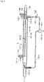
- An exhaust gas treatment equipment for a marine diesel engine shown in Figure 3 as a device of a third example has a configuration in which in the device of the second example shown in Figure 2 , a PM-free scrubber 11, which is the same as the PM-free scrubber 11 installed in the PM-low-concentration exhaust gas introduction pipe 4, is installed in the recirculation pipe 14-2 for recirculating combustion exhaust gas from the PM burning unit 3 to the exhaust gas introduction pipe 1-1a of the electric precipitation unit 1.
- the configuration is provided with an discharge electrode 1-2 for charging particulate matters contained in exhaust gas of a marine diesel engine using low-quality fuel such as fuel oil or the like containing high-concentration sulfur components as its fuel; a tubular collection pipe 1-1 forming a precipitation electrode for collecting the charged particulate matters; and separating and collecting means 2-1 of a cyclone system for separating and collecting the particulate matters separated from the tubular collection pipe 1-1, and in this structure, a PM-free scrubber 11 that removes SO x contained in exhaust gas, but hardly removes any PM by utilizing difference in diffusion speeds between gas and particles is installed on the low-concentration exhaust gas delivery pipe 4 of PM 10 so that SO x is removed from the exhaust gas to be discharged to the atmosphere, and a cyclone collection means constituted by the same tangent-type cyclone 2-1a as described earlier is installed in the PM-high-concentration exhaust gas pipe 5-2 from the PM-high-
- the PM burning unit 3 is designed such that a hopper 2-1b is installed right below a corn-shaped portion right below the lower portion of the tangent-type cyclone 2-1a, and right below the hopper, a stocker 3'-1 that has an inner capacity larger than that of the hopper 2-1b and also serves as the PM incinerator is installed, with a shutter 2-1c that holds PM precipitated and accumulated in the hopper and also allows the PM to drop down into the hopper being interposed therebetween.
- the stocker 3'-1 also serving as the PM incinerator is designed to have a built-in electric heater 3'-1a and control the burning temperature, the amount of intake air, the flow rate, or the like of the combustion exhaust gas by the controller 3-2.
- the shutter 2-1c is opened to allow the PM to drop down inside the stocker 3'-1 right below the hopper, and the shutter 2-1c is then closed to stock.
- a combustion exhaust gas from the stocker 3'-1 also serving as the PM incinerator is designed to be recirculated into the exhaust gas introduction pipe 1-1a of the electric precipitation unit 1 through the recirculation pipe 14-2.
- the device of the present example is designed to have a configuration in which a PM-free scrubber 11, which is the same as the PM-free scrubber 11 installed in the PM-low-concentration exhaust gas introduction pipe 4, is installed in the recirculation pipe 14-2.
- Reference numerals 14-1a and 14-2a respectively represent blowers for applying kinetic energy to exhaust gas flows respectively flowing through the recirculation pipes 14-1 and 14-2.
- the device in the present example also has a configuration in which the tip ends of the recirculation pipes 14-1 and 14-2 are made to protrude inside the exhaust gas introduction pipe 1-1a by taking an ejector effect into consideration, with the tip end openings being bent to be directed to the exhaust gas outflow direction.
- the stocker 3'-1 also serving as the PM incinerator may be prepared as an incinerator that uses a burner (not shown) in place of the electric heater 3'-1a.
- An exhaust gas treatment equipment for a marine diesel engine shown in Figure 4 as a device of a fourth example has a system in which a mixed flow of PM combustion exhaust gas and a low-concentration gas is supplied to a PM-free scrubber, and its configuration is made such that the recirculation pipe 12 of combustion exhaust gas from the PM incinerator 3-1 of the PM burning unit 3 of the device of first example shown in Figure 1 is allowed to protrude into an upstream side pipe of the PM-free scrubber 11 of the low-concentration exhaust gas introduction pipe 4 for PM 10.
- This cyclone collection means 2-1 is constituted by a single tangent-type cyclone 2-1a connected to a PM-high-concentration exhaust gas delivery unit 1-1b of the collection pipe 1-1 through a communication pipe 5-1, and between the tangent-type cyclone 2-1a and the PM-low-concentration exhaust gas delivery pipe 4, an exhaust pipe 6-1 for use in joining a purified gas after having passed through the tangent-type cyclone 2-1a to a PM-low-concentration exhaust gas flowing the inside of the PM-low-concentration exhaust gas delivery pipe 4 is disposed, and in the PM-low-concentration exhaust gas delivery pipe 4, a flow-rate control dumper 7 for carrying out flow-rate adjustments on PM-high-concentration exhaust gas inflow rate and inflow speed into the tangent-type cyclone 2-1a and a PM-low-concentration exhaust gas discharge amount is installed.
- the PM burning unit 3 to be installed for burning PM is constituted by the PM incinerator 3-1 having a built-in electric heater 3-1a in which the burning temperature, the amount of intake air, the flow rate of the combustion exhaust gas, or the like, are controlled by the controller 3-2.
- a recirculation pipe 15 for use in recirculating combustion exhaust gas from the PM incinerator 3-1 to the upstream side of the PM-free scrubber 11 of the low-concentration exhaust gas delivery pipe 4 for PM 10 is installed.
- the recirculation pipe 15 also has its tip end protruded into the PM-low-concentration exhaust gas delivery pipe 4.
- reference numeral 15a represents a blower for applying kinetic energy to an exhaust gas flow flowing through the recirculation pipe 15.
- a PM combustion exhaust gas containing high-concentration sulfur components generated upon burning the PM 10 is recirculated onto the upstream side of the PM-free scrubber 11 of the PM-low-concentration exhaust gas delivery pipe 4 through the recirculation pipe 15 to be mixed with the PM-low-concentration exhaust gas, and supplied to the PM-free scrubber 11.
- an exhaust gas to be discharged to the atmosphere is formed into a gas from which sulfur components are removed although PM remains therein so that the atmospheric environment can be preserved.
- the treatment water from the PM-free scrubber 11 contains high-concentration sulfur components, but contains hardly any PM, the discharge into the ocean such as a scrubber through operation is possible, and the treatment can be carried out by using a small-sized treatment device with a small number of processes which is easily controlled.
- the PM combustion exhaust gas recirculation pipe 15 to the PM-low-concentration exhaust gas delivery pipe 4
- since corrosive PM combustion exhaust gas is prevented from flowing into the electric precipitation unit 1 and the separating and collecting unit 2 it is not necessary to use highly corrosion resistant materials for these members (collection pipe, electrode, or the like) and durability is easily ensured at low costs.
- An exhaust gas treatment equipment for a marine diesel engine shown in Figure 5 as a device of a fifth example has a system in which PM combustion exhaust gas is directly supplied to the PM-free scrubber 11, and its configuration is made such that an discharge electrode 1-2 for charging particulate matters contained in exhaust gas of a marine diesel engine using low-quality fuel such as fuel oil or the like containing high-concentration sulfur components as its fuel and a tubular collection pipe 1-1 forming a precipitation electrode for collecting the charged particulate matters are installed, and separating and collecting means 2-1 of a cyclone system for separating and collecting the particulate matters separated from the tubular collection pipe 1-1 is further installed, and in this configuration, by installing a PM-free scrubber 11 that removes SO x contained in exhaust gas, but hardly removes any PM by utilizing difference in diffusion speeds between gas and particles in a low-concentration exhaust gas delivery pipe 4 for PM 10, SO x is removed from an exhaust gas to be discharged to the atmosphere, and a separating and collecting unit 2, formed on the downstream side of the electric
- This cyclone collection means 2-1 is constituted by a single tangent-type cyclone 2-1a that is connected to the PM-high-concentration exhaust gas delivery unit 1-1b of the collection pipe 1-1 through a communication pipe 5-1 and a PM-high-concentration exhaust gas pipe 5-2 so that by introducing a PM-high-concentration exhaust gas flow discharged by the PM-high-concentration exhaust gas delivery unit 1-1b into the tangent-type cyclone 2-1a, large-diameter particles are collected and treated, and an exhaust gas flow containing small-diameter particles that have not been removed in the same cyclone is pressure-fed and recirculated to the exhaust gas introduction pipe 1-1a via the recirculation pipe 16.
- Reference numeral 16a represents a blower for applying kinetic energy to an exhaust gas flow flowing through the recirculation pipe 16.
- a PM burning unit 3 installed to burn the PM is constituted by a PM incinerator 3-1 having a built-in electric heater 3-1a in which the burning temperature, the amount of intake air, the flow rate of the combustion exhaust gas, or the like are controlled by a controller 3-2.
- the device of the present example is mainly characterized in that a recirculation pipe 17, which directly supplies combustion exhaust gas from the PM incinerator 3-1 to the PM-free scrubber 11 installed in the PM-low-concentration exhaust gas delivery pipe 4, is installed.
- Reference numeral 17a represents a blower for applying kinetic energy to an exhaust gas flow flowing inside the recirculation pipe 17, in the same manner as described earlier.
- the PM-low-concentration exhaust gas and the PM combustion exhaust gas supplied to the PM-free scrubber 11 are formed into a gas from which sulfur components are removed although PM remains therein so that the atmospheric environment can be preserved. Additionally, since the treatment water from the PM-free scrubber 11 contains high-concentration sulfur components, but contains hardly any PM, the discharge into the ocean such as a scrubber-through operation or the like is possible, and the treatment can be carried out by using a small-sized treatment device with a small number of processes which is easily controlled. Moreover, corrosive PM combustion exhaust gas is prevented from flowing into the electric precipitation unit 1 and the separating and collecting unit 2, it is not necessary to use highly corrosion resistant materials for these members (collection pipe, electrode, or the like) and durability is easily ensured at low costs.
- An exhaust gas treatment equipment for a marine diesel engine shown in Figure 6 as a device of a sixth example, has a configuration in which a plurality of stockers also serving as PM incinerators described in the device of the second example shown in Figure 2 are installed so that PM alternate collections and alternate burning operations can be carried out.
- the device in accordance with the present example is provided with an discharge electrode 1-2 for charging particulate matters contained in exhaust gas of a marine diesel engine using low-quality fuel such as fuel oil or the like containing high-concentration sulfur components as its fuel, a tubular collection pipe 1-1 forming a precipitation electrode for collecting the charged particulate matters are installed, and separating and collecting means 2-1 of a cyclone system for separating and collecting the particulate matters separated from the tubular collection pipe 1-1 is further installed, and by installing a PM-free scrubber 11 that removes SO x contained in exhaust gas, but hardly removes any PM by utilizing difference in diffusion speeds between gas and particles in a low-concentration exhaust gas delivery pipe 4 for PM 10, SO x is removed from an exhaust gas to be discharged to the atmosphere, and in this configuration, a cyclone collection means constituted by the same tangent-type separating and collecting unit 2-1a described earlier, is formed on the high-concentration
- the PM burning unit 3 has a configuration in which a multiple branch pipe 2-1e that has a built-in switching valve 2-1d and has a two forked portion or the like is installed on a hopper 2-1b right below a cone-shaped portion of a lower portion of the tangent-type cyclone 2-1a, and at each of the lower ends of the multiply branched portions of the multiple branch pipe 2-1e, a stocker 3'-1 having an inner capacity larger than that of the hopper 2-1b and also serving a PM incinerator is provided, with a shutter 2-1c for holding PM precipitated and accumulated inside the hopper 2-1b and for allowing the PM to drop down being interposed therebetween.
- the stocker 3'-1 also serving as the PM incinerator has a built-in electric heater 3'-1a inside thereof, and is designed to control the burning temperature, the amount of intake air, the flow rate of the combustion exhaust gas, etc. by using the controller 3-2. Additionally, in the case of the stocker 3'-1 also serving as the PM incinerator, PM is precipitated and accumulated inside the hopper 2-1b, and upon reaching the hopper capacity limit, the shutter 2-1c is opened so that the PM is allowed to drop down into the stocker 3'-1 right below the hopper, and thereafter, the shutter 2-1c is closed to stock.
- a combustion exhaust gas from the stocker 3-1 also serving as the PM incinerator is designed to be recirculated into the exhaust gas introduction pipe 1-1a of the electric precipitation unit 1 through the recirculation piping 14-2.
- the device of the present example also has the tip ends of the recirculation pipes 14-1 and 14-2 protruded into the exhaust gas introduction pipe 1-1a, with the tip end openings being bent to be directed to the exhaust gas outflow direction, by taking an ejector effect into consideration.
- the stocker 3'-1 also serving as the PM incinerator may be prepared as an incinerator that uses a burner (not shown) in place of the electric heater 3'-1a.
Applications Claiming Priority (2)
| Application Number | Priority Date | Filing Date | Title |
|---|---|---|---|
| JP2014079715A JP6238823B2 (ja) | 2014-04-08 | 2014-04-08 | 高濃度に硫黄成分を含有する低質燃料を使用する船舶用ディーゼルエンジンの排ガス処理装置 |
| PCT/JP2015/060982 WO2015156320A1 (ja) | 2014-04-08 | 2015-04-08 | 高濃度に硫黄成分を含有する低質燃料を使用する船舶用ディーゼルエンジンの排ガス処理装置 |
Publications (2)
| Publication Number | Publication Date |
|---|---|
| EP3130773A1 true EP3130773A1 (de) | 2017-02-15 |
| EP3130773A4 EP3130773A4 (de) | 2017-03-08 |
Family
ID=54287893
Family Applications (1)
| Application Number | Title | Priority Date | Filing Date |
|---|---|---|---|
| EP15777369.8A Withdrawn EP3130773A4 (de) | 2014-04-08 | 2015-04-08 | Abgasreinigungsvorrichtung für einen schiffsdieselmotor mit minderwertigem brennstoff mit hohem schwefelgehalt |
Country Status (6)
| Country | Link |
|---|---|
| EP (1) | EP3130773A4 (de) |
| JP (1) | JP6238823B2 (de) |
| KR (1) | KR101828734B1 (de) |
| CN (1) | CN106170610B (de) |
| MA (1) | MA39858A (de) |
| WO (1) | WO2015156320A1 (de) |
Cited By (9)
| Publication number | Priority date | Publication date | Assignee | Title |
|---|---|---|---|---|
| US11124714B2 (en) | 2020-02-19 | 2021-09-21 | Marathon Petroleum Company Lp | Low sulfur fuel oil blends for stability enhancement and associated methods |
| US20220184551A1 (en) * | 2019-03-11 | 2022-06-16 | University Of Southern California | Systems and methods for plasma-based remediation |
| EP3938081A4 (de) * | 2019-03-11 | 2023-01-25 | University Of Southern California | Systeme und verfahren zur plasmabasierten sanierung von sox und nox |
| US11802257B2 (en) | 2022-01-31 | 2023-10-31 | Marathon Petroleum Company Lp | Systems and methods for reducing rendered fats pour point |
| US11860069B2 (en) | 2021-02-25 | 2024-01-02 | Marathon Petroleum Company Lp | Methods and assemblies for determining and using standardized spectral responses for calibration of spectroscopic analyzers |
| US11891581B2 (en) | 2017-09-29 | 2024-02-06 | Marathon Petroleum Company Lp | Tower bottoms coke catching device |
| US11898109B2 (en) | 2021-02-25 | 2024-02-13 | Marathon Petroleum Company Lp | Assemblies and methods for enhancing control of hydrotreating and fluid catalytic cracking (FCC) processes using spectroscopic analyzers |
| US11905468B2 (en) | 2021-02-25 | 2024-02-20 | Marathon Petroleum Company Lp | Assemblies and methods for enhancing control of fluid catalytic cracking (FCC) processes using spectroscopic analyzers |
| US11970664B2 (en) | 2023-05-08 | 2024-04-30 | Marathon Petroleum Company Lp | Methods and systems for enhancing processing of hydrocarbons in a fluid catalytic cracking unit using a renewable additive |
Families Citing this family (8)
| Publication number | Priority date | Publication date | Assignee | Title |
|---|---|---|---|---|
| JP2016151196A (ja) * | 2015-02-16 | 2016-08-22 | 三菱重工業株式会社 | 排ガス再循環システム、およびこれを備えた舶用エンジン |
| JP6579150B2 (ja) * | 2017-04-25 | 2019-09-25 | トヨタ自動車株式会社 | 排ガス浄化装置 |
| JP7144172B2 (ja) * | 2018-04-03 | 2022-09-29 | トリニティ工業株式会社 | 電界浄化装置及びワーク乾燥システム |
| JP2020195954A (ja) * | 2019-05-31 | 2020-12-10 | 臼井国際産業株式会社 | 電気集塵装置 |
| KR102315711B1 (ko) * | 2019-08-08 | 2021-10-21 | 황종덕 | 배기가스 정화장치 |
| KR102422754B1 (ko) * | 2020-11-24 | 2022-07-20 | 한국기계연구원 | 엔진 배출 입자상 물질의 제거장치를 이용한 입자상 물질의 제거방법 |
| CN113996150B (zh) * | 2021-11-03 | 2022-07-15 | 福建三宝钢铁有限公司 | 一种高效脱硫脱硝方法及系统 |
| JP7411025B1 (ja) | 2022-07-05 | 2024-01-10 | 株式会社新来島どっく | ドレン受けホッパー装置 |
Family Cites Families (8)
| Publication number | Priority date | Publication date | Assignee | Title |
|---|---|---|---|---|
| JPH0521118U (ja) * | 1991-08-30 | 1993-03-19 | 株式会社明電舎 | デイーゼルエンジン用消煙装置 |
| AU2003252127B2 (en) * | 2002-07-25 | 2009-06-18 | Kammel, Refaat A | System and method for reducting pollutants from diesel engine exhaust |
| JP2008127998A (ja) * | 2006-11-16 | 2008-06-05 | Mitsubishi Fuso Truck & Bus Corp | 内燃機関の排気浄化装置 |
| JP5688806B2 (ja) * | 2009-10-14 | 2015-03-25 | 臼井国際産業株式会社 | 電気式排気ガス処理方法および電気式排気ガス処理装置 |
| JP5863087B2 (ja) * | 2010-11-16 | 2016-02-16 | 臼井国際産業株式会社 | 重油以下の低質燃料を使用する大排気量ディーゼルエンジン用排ガス処理装置 |
| JP6041418B2 (ja) * | 2010-12-16 | 2016-12-07 | 臼井国際産業株式会社 | 重油以下の低質燃料を使用する大排気量船舶用ディーゼルエンジンの排気ガス浄化装置 |
| JP6062660B2 (ja) * | 2012-05-15 | 2017-01-18 | 臼井国際産業株式会社 | 重油より低質な燃料を使用する大排気量船舶用ディーゼルエンジン排ガス処理装置 |
| JP2014055567A (ja) * | 2012-09-13 | 2014-03-27 | Kawasaki Heavy Ind Ltd | 排気ガス浄化装置及びこれを備える船舶機関システム |
-
2014
- 2014-04-08 JP JP2014079715A patent/JP6238823B2/ja not_active Expired - Fee Related
-
2015
- 2015-04-08 WO PCT/JP2015/060982 patent/WO2015156320A1/ja active Application Filing
- 2015-04-08 CN CN201580017389.3A patent/CN106170610B/zh not_active Expired - Fee Related
- 2015-04-08 EP EP15777369.8A patent/EP3130773A4/de not_active Withdrawn
- 2015-04-08 MA MA039858A patent/MA39858A/fr unknown
- 2015-04-08 KR KR1020167031113A patent/KR101828734B1/ko active IP Right Grant
Cited By (20)
| Publication number | Priority date | Publication date | Assignee | Title |
|---|---|---|---|---|
| US11891581B2 (en) | 2017-09-29 | 2024-02-06 | Marathon Petroleum Company Lp | Tower bottoms coke catching device |
| US20220184551A1 (en) * | 2019-03-11 | 2022-06-16 | University Of Southern California | Systems and methods for plasma-based remediation |
| EP3938081A4 (de) * | 2019-03-11 | 2023-01-25 | University Of Southern California | Systeme und verfahren zur plasmabasierten sanierung von sox und nox |
| EP3938644A4 (de) * | 2019-03-11 | 2023-04-05 | University Of Southern California | Systeme und verfahren zur plasmagestützten sanierung |
| US11905479B2 (en) | 2020-02-19 | 2024-02-20 | Marathon Petroleum Company Lp | Low sulfur fuel oil blends for stability enhancement and associated methods |
| US11352578B2 (en) | 2020-02-19 | 2022-06-07 | Marathon Petroleum Company Lp | Low sulfur fuel oil blends for stabtility enhancement and associated methods |
| US11352577B2 (en) | 2020-02-19 | 2022-06-07 | Marathon Petroleum Company Lp | Low sulfur fuel oil blends for paraffinic resid stability and associated methods |
| US11384301B2 (en) | 2020-02-19 | 2022-07-12 | Marathon Petroleum Company Lp | Low sulfur fuel oil blends for stability enhancement and associated methods |
| US11667858B2 (en) | 2020-02-19 | 2023-06-06 | Marathon Petroleum Company Lp | Low sulfur fuel oil blends for stability enhancement and associated methods |
| US11920096B2 (en) | 2020-02-19 | 2024-03-05 | Marathon Petroleum Company Lp | Low sulfur fuel oil blends for paraffinic resid stability and associated methods |
| US11124714B2 (en) | 2020-02-19 | 2021-09-21 | Marathon Petroleum Company Lp | Low sulfur fuel oil blends for stability enhancement and associated methods |
| US11975316B2 (en) | 2020-05-07 | 2024-05-07 | Marathon Petroleum Company Lp | Methods and reforming systems for re-dispersing platinum on reforming catalyst |
| US11885739B2 (en) | 2021-02-25 | 2024-01-30 | Marathon Petroleum Company Lp | Methods and assemblies for determining and using standardized spectral responses for calibration of spectroscopic analyzers |
| US11898109B2 (en) | 2021-02-25 | 2024-02-13 | Marathon Petroleum Company Lp | Assemblies and methods for enhancing control of hydrotreating and fluid catalytic cracking (FCC) processes using spectroscopic analyzers |
| US11906423B2 (en) | 2021-02-25 | 2024-02-20 | Marathon Petroleum Company Lp | Methods, assemblies, and controllers for determining and using standardized spectral responses for calibration of spectroscopic analyzers |
| US11905468B2 (en) | 2021-02-25 | 2024-02-20 | Marathon Petroleum Company Lp | Assemblies and methods for enhancing control of fluid catalytic cracking (FCC) processes using spectroscopic analyzers |
| US11921035B2 (en) | 2021-02-25 | 2024-03-05 | Marathon Petroleum Company Lp | Methods and assemblies for determining and using standardized spectral responses for calibration of spectroscopic analyzers |
| US11860069B2 (en) | 2021-02-25 | 2024-01-02 | Marathon Petroleum Company Lp | Methods and assemblies for determining and using standardized spectral responses for calibration of spectroscopic analyzers |
| US11802257B2 (en) | 2022-01-31 | 2023-10-31 | Marathon Petroleum Company Lp | Systems and methods for reducing rendered fats pour point |
| US11970664B2 (en) | 2023-05-08 | 2024-04-30 | Marathon Petroleum Company Lp | Methods and systems for enhancing processing of hydrocarbons in a fluid catalytic cracking unit using a renewable additive |
Also Published As
| Publication number | Publication date |
|---|---|
| EP3130773A4 (de) | 2017-03-08 |
| JP6238823B2 (ja) | 2017-11-29 |
| JP2015200230A (ja) | 2015-11-12 |
| MA39858A (fr) | 2017-02-15 |
| CN106170610B (zh) | 2019-08-13 |
| CN106170610A (zh) | 2016-11-30 |
| KR101828734B1 (ko) | 2018-03-29 |
| KR20160135838A (ko) | 2016-11-28 |
| WO2015156320A1 (ja) | 2015-10-15 |
Similar Documents
| Publication | Publication Date | Title |
|---|---|---|
| EP3130773A1 (de) | Abgasreinigungsvorrichtung für einen schiffsdieselmotor mit minderwertigem brennstoff mit hohem schwefelgehalt | |
| JP2015200230A5 (de) | ||
| JP6319794B2 (ja) | 高濃度に硫黄成分を含有する重油等の低質燃料を使用する船舶用ディーゼルエンジンの排気ガス浄化装置 | |
| EP3139009B1 (de) | Abgasreinigungsvorrichtung für einen schiffsdieselmotor mit minderwertigem brennstoff mit hohem schwefelgehalt | |
| JP6041418B2 (ja) | 重油以下の低質燃料を使用する大排気量船舶用ディーゼルエンジンの排気ガス浄化装置 | |
| CN107208514B (zh) | 船舶用柴油发动机的废气净化装置用洗涤器 | |
| KR101801501B1 (ko) | 고농도로 황 성분을 함유하는 중유 등의 저질 연료를 사용하는 선박용 디젤 엔진의 배기가스 정화 장치 | |
| JP2012140928A5 (de) | ||
| JP2014224527A5 (de) | ||
| JP2015200215A5 (de) | ||
| JP5843701B2 (ja) | 廃水処理装置、排気再循環ユニット、エンジンシステム、及び船舶 | |
| KR20150024437A (ko) | 배기가스 정화 장치 및 이를 구비한 선박 기관 시스템 | |
| US10196949B2 (en) | Method and system for the removal of particulate matter from engine exhaust gas or process equipment | |
| JP5889229B2 (ja) | 再循環排ガス浄化装置及び再循環排ガス浄化方法 |
Legal Events
| Date | Code | Title | Description |
|---|---|---|---|
| STAA | Information on the status of an ep patent application or granted ep patent |
Free format text: STATUS: THE INTERNATIONAL PUBLICATION HAS BEEN MADE |
|
| PUAI | Public reference made under article 153(3) epc to a published international application that has entered the european phase |
Free format text: ORIGINAL CODE: 0009012 |
|
| STAA | Information on the status of an ep patent application or granted ep patent |
Free format text: STATUS: REQUEST FOR EXAMINATION WAS MADE |
|
| 17P | Request for examination filed |
Effective date: 20161028 |
|
| AK | Designated contracting states |
Kind code of ref document: A1 Designated state(s): AL AT BE BG CH CY CZ DE DK EE ES FI FR GB GR HR HU IE IS IT LI LT LU LV MC MK MT NL NO PL PT RO RS SE SI SK SM TR |
|
| AX | Request for extension of the european patent |
Extension state: BA ME |
|
| STAA | Information on the status of an ep patent application or granted ep patent |
Free format text: STATUS: EXAMINATION IS IN PROGRESS |
|
| A4 | Supplementary search report drawn up and despatched |
Effective date: 20170208 |
|
| RIC1 | Information provided on ipc code assigned before grant |
Ipc: F01N 3/08 20060101ALI20170202BHEP Ipc: F01N 3/24 20060101ALI20170202BHEP Ipc: F01N 3/02 20060101ALI20170202BHEP Ipc: B01D 50/00 20060101ALI20170202BHEP Ipc: F01N 3/037 20060101ALI20170202BHEP Ipc: B01D 53/50 20060101ALI20170202BHEP Ipc: F01N 3/033 20060101AFI20170202BHEP Ipc: F01N 3/01 20060101ALI20170202BHEP |
|
| 17Q | First examination report despatched |
Effective date: 20170303 |
|
| STAA | Information on the status of an ep patent application or granted ep patent |
Free format text: STATUS: EXAMINATION IS IN PROGRESS |
|
| STAA | Information on the status of an ep patent application or granted ep patent |
Free format text: STATUS: THE APPLICATION IS DEEMED TO BE WITHDRAWN |
|
| 18D | Application deemed to be withdrawn |
Effective date: 20210212 |