WO2015156320A1 - Exhaust gas treatment device for marine diesel engine that uses low-quality fuel containing high concentration of sulfur component - Google Patents
Exhaust gas treatment device for marine diesel engine that uses low-quality fuel containing high concentration of sulfur component Download PDFInfo
- Publication number
- WO2015156320A1 WO2015156320A1 PCT/JP2015/060982 JP2015060982W WO2015156320A1 WO 2015156320 A1 WO2015156320 A1 WO 2015156320A1 JP 2015060982 W JP2015060982 W JP 2015060982W WO 2015156320 A1 WO2015156320 A1 WO 2015156320A1
- Authority
- WO
- WIPO (PCT)
- Prior art keywords
- exhaust gas
- pipe
- concentration
- low
- cyclone
- Prior art date
Links
Images


Classifications
-
- F—MECHANICAL ENGINEERING; LIGHTING; HEATING; WEAPONS; BLASTING
- F01—MACHINES OR ENGINES IN GENERAL; ENGINE PLANTS IN GENERAL; STEAM ENGINES
- F01N—GAS-FLOW SILENCERS OR EXHAUST APPARATUS FOR MACHINES OR ENGINES IN GENERAL; GAS-FLOW SILENCERS OR EXHAUST APPARATUS FOR INTERNAL COMBUSTION ENGINES
- F01N3/00—Exhaust or silencing apparatus having means for purifying, rendering innocuous, or otherwise treating exhaust
- F01N3/02—Exhaust or silencing apparatus having means for purifying, rendering innocuous, or otherwise treating exhaust for cooling, or for removing solid constituents of, exhaust
- F01N3/037—Exhaust or silencing apparatus having means for purifying, rendering innocuous, or otherwise treating exhaust for cooling, or for removing solid constituents of, exhaust by means of inertial or centrifugal separators, e.g. of cyclone type, optionally combined or associated with agglomerators
-
- B—PERFORMING OPERATIONS; TRANSPORTING
- B01—PHYSICAL OR CHEMICAL PROCESSES OR APPARATUS IN GENERAL
- B01D—SEPARATION
- B01D53/00—Separation of gases or vapours; Recovering vapours of volatile solvents from gases; Chemical or biological purification of waste gases, e.g. engine exhaust gases, smoke, fumes, flue gases, aerosols
- B01D53/32—Separation of gases or vapours; Recovering vapours of volatile solvents from gases; Chemical or biological purification of waste gases, e.g. engine exhaust gases, smoke, fumes, flue gases, aerosols by electrical effects other than those provided for in group B01D61/00
- B01D53/323—Separation of gases or vapours; Recovering vapours of volatile solvents from gases; Chemical or biological purification of waste gases, e.g. engine exhaust gases, smoke, fumes, flue gases, aerosols by electrical effects other than those provided for in group B01D61/00 by electrostatic effects or by high-voltage electric fields
-
- B—PERFORMING OPERATIONS; TRANSPORTING
- B03—SEPARATION OF SOLID MATERIALS USING LIQUIDS OR USING PNEUMATIC TABLES OR JIGS; MAGNETIC OR ELECTROSTATIC SEPARATION OF SOLID MATERIALS FROM SOLID MATERIALS OR FLUIDS; SEPARATION BY HIGH-VOLTAGE ELECTRIC FIELDS
- B03C—MAGNETIC OR ELECTROSTATIC SEPARATION OF SOLID MATERIALS FROM SOLID MATERIALS OR FLUIDS; SEPARATION BY HIGH-VOLTAGE ELECTRIC FIELDS
- B03C3/00—Separating dispersed particles from gases or vapour, e.g. air, by electrostatic effect
- B03C3/017—Combinations of electrostatic separation with other processes, not otherwise provided for
-
- B—PERFORMING OPERATIONS; TRANSPORTING
- B03—SEPARATION OF SOLID MATERIALS USING LIQUIDS OR USING PNEUMATIC TABLES OR JIGS; MAGNETIC OR ELECTROSTATIC SEPARATION OF SOLID MATERIALS FROM SOLID MATERIALS OR FLUIDS; SEPARATION BY HIGH-VOLTAGE ELECTRIC FIELDS
- B03C—MAGNETIC OR ELECTROSTATIC SEPARATION OF SOLID MATERIALS FROM SOLID MATERIALS OR FLUIDS; SEPARATION BY HIGH-VOLTAGE ELECTRIC FIELDS
- B03C3/00—Separating dispersed particles from gases or vapour, e.g. air, by electrostatic effect
- B03C3/34—Constructional details or accessories or operation thereof
- B03C3/40—Electrode constructions
- B03C3/41—Ionising-electrodes
-
- B—PERFORMING OPERATIONS; TRANSPORTING
- B03—SEPARATION OF SOLID MATERIALS USING LIQUIDS OR USING PNEUMATIC TABLES OR JIGS; MAGNETIC OR ELECTROSTATIC SEPARATION OF SOLID MATERIALS FROM SOLID MATERIALS OR FLUIDS; SEPARATION BY HIGH-VOLTAGE ELECTRIC FIELDS
- B03C—MAGNETIC OR ELECTROSTATIC SEPARATION OF SOLID MATERIALS FROM SOLID MATERIALS OR FLUIDS; SEPARATION BY HIGH-VOLTAGE ELECTRIC FIELDS
- B03C3/00—Separating dispersed particles from gases or vapour, e.g. air, by electrostatic effect
- B03C3/34—Constructional details or accessories or operation thereof
- B03C3/40—Electrode constructions
- B03C3/45—Collecting-electrodes
- B03C3/49—Collecting-electrodes tubular
-
- F—MECHANICAL ENGINEERING; LIGHTING; HEATING; WEAPONS; BLASTING
- F01—MACHINES OR ENGINES IN GENERAL; ENGINE PLANTS IN GENERAL; STEAM ENGINES
- F01N—GAS-FLOW SILENCERS OR EXHAUST APPARATUS FOR MACHINES OR ENGINES IN GENERAL; GAS-FLOW SILENCERS OR EXHAUST APPARATUS FOR INTERNAL COMBUSTION ENGINES
- F01N3/00—Exhaust or silencing apparatus having means for purifying, rendering innocuous, or otherwise treating exhaust
- F01N3/01—Exhaust or silencing apparatus having means for purifying, rendering innocuous, or otherwise treating exhaust by means of electric or electrostatic separators
-
- F—MECHANICAL ENGINEERING; LIGHTING; HEATING; WEAPONS; BLASTING
- F01—MACHINES OR ENGINES IN GENERAL; ENGINE PLANTS IN GENERAL; STEAM ENGINES
- F01N—GAS-FLOW SILENCERS OR EXHAUST APPARATUS FOR MACHINES OR ENGINES IN GENERAL; GAS-FLOW SILENCERS OR EXHAUST APPARATUS FOR INTERNAL COMBUSTION ENGINES
- F01N3/00—Exhaust or silencing apparatus having means for purifying, rendering innocuous, or otherwise treating exhaust
- F01N3/02—Exhaust or silencing apparatus having means for purifying, rendering innocuous, or otherwise treating exhaust for cooling, or for removing solid constituents of, exhaust
-
- B—PERFORMING OPERATIONS; TRANSPORTING
- B01—PHYSICAL OR CHEMICAL PROCESSES OR APPARATUS IN GENERAL
- B01D—SEPARATION
- B01D2257/00—Components to be removed
- B01D2257/30—Sulfur compounds
- B01D2257/302—Sulfur oxides
-
- B—PERFORMING OPERATIONS; TRANSPORTING
- B01—PHYSICAL OR CHEMICAL PROCESSES OR APPARATUS IN GENERAL
- B01D—SEPARATION
- B01D2258/00—Sources of waste gases
- B01D2258/01—Engine exhaust gases
- B01D2258/012—Diesel engines and lean burn gasoline engines
-
- B—PERFORMING OPERATIONS; TRANSPORTING
- B01—PHYSICAL OR CHEMICAL PROCESSES OR APPARATUS IN GENERAL
- B01D—SEPARATION
- B01D2259/00—Type of treatment
- B01D2259/45—Gas separation or purification devices adapted for specific applications
- B01D2259/4566—Gas separation or purification devices adapted for specific applications for use in transportation means
-
- B—PERFORMING OPERATIONS; TRANSPORTING
- B03—SEPARATION OF SOLID MATERIALS USING LIQUIDS OR USING PNEUMATIC TABLES OR JIGS; MAGNETIC OR ELECTROSTATIC SEPARATION OF SOLID MATERIALS FROM SOLID MATERIALS OR FLUIDS; SEPARATION BY HIGH-VOLTAGE ELECTRIC FIELDS
- B03C—MAGNETIC OR ELECTROSTATIC SEPARATION OF SOLID MATERIALS FROM SOLID MATERIALS OR FLUIDS; SEPARATION BY HIGH-VOLTAGE ELECTRIC FIELDS
- B03C2201/00—Details of magnetic or electrostatic separation
- B03C2201/10—Ionising electrode has multiple serrated ends or parts
-
- B—PERFORMING OPERATIONS; TRANSPORTING
- B03—SEPARATION OF SOLID MATERIALS USING LIQUIDS OR USING PNEUMATIC TABLES OR JIGS; MAGNETIC OR ELECTROSTATIC SEPARATION OF SOLID MATERIALS FROM SOLID MATERIALS OR FLUIDS; SEPARATION BY HIGH-VOLTAGE ELECTRIC FIELDS
- B03C—MAGNETIC OR ELECTROSTATIC SEPARATION OF SOLID MATERIALS FROM SOLID MATERIALS OR FLUIDS; SEPARATION BY HIGH-VOLTAGE ELECTRIC FIELDS
- B03C2201/00—Details of magnetic or electrostatic separation
- B03C2201/30—Details of magnetic or electrostatic separation for use in or with vehicles
-
- F—MECHANICAL ENGINEERING; LIGHTING; HEATING; WEAPONS; BLASTING
- F01—MACHINES OR ENGINES IN GENERAL; ENGINE PLANTS IN GENERAL; STEAM ENGINES
- F01N—GAS-FLOW SILENCERS OR EXHAUST APPARATUS FOR MACHINES OR ENGINES IN GENERAL; GAS-FLOW SILENCERS OR EXHAUST APPARATUS FOR INTERNAL COMBUSTION ENGINES
- F01N2590/00—Exhaust or silencing apparatus adapted to particular use, e.g. for military applications, airplanes, submarines
- F01N2590/02—Exhaust or silencing apparatus adapted to particular use, e.g. for military applications, airplanes, submarines for marine vessels or naval applications
-
- Y—GENERAL TAGGING OF NEW TECHNOLOGICAL DEVELOPMENTS; GENERAL TAGGING OF CROSS-SECTIONAL TECHNOLOGIES SPANNING OVER SEVERAL SECTIONS OF THE IPC; TECHNICAL SUBJECTS COVERED BY FORMER USPC CROSS-REFERENCE ART COLLECTIONS [XRACs] AND DIGESTS
- Y02—TECHNOLOGIES OR APPLICATIONS FOR MITIGATION OR ADAPTATION AGAINST CLIMATE CHANGE
- Y02T—CLIMATE CHANGE MITIGATION TECHNOLOGIES RELATED TO TRANSPORTATION
- Y02T10/00—Road transport of goods or passengers
- Y02T10/10—Internal combustion engine [ICE] based vehicles
- Y02T10/12—Improving ICE efficiencies
Definitions
- the present invention removes and purifies harmful gases such as sulfur oxides contained in the exhaust gas of marine diesel engines, and uses heavy oil containing heavy sulfur components [heavy oil (heavy oil ( FuelOil is used in the marine industry in diesel oil (DieselOil: DO), marine diesel fuel (MarineDieselFuel: MDF) or marine diesel oil (MarineDieselOil: MDO), marine fuel oil (MarineFuelOil: MFO), heavy fuel oil (HeOil: Heoil) HFO) and residual fuel oil (ResidualFuelOil: RFO).
- these symbols are collectively referred to as heavy oil (DieselOil).
- the present invention relates to an exhaust gas purifying apparatus provided with a device for collecting PM from exhaust gas and incinerating the collected PM in a ship.
- Diesel engines are widely used as power sources for various ships, power generators, large construction machines, and various automobiles.
- Particulate matter mainly composed of carbon contained in exhaust gas discharged from diesel engines Particulate Matter (hereinafter referred to as “PM”), sulfur oxide (hereinafter referred to as “SOx”), and nitrogen oxide (hereinafter referred to as “NOx”) not only cause air pollution, as is well known. Since it is a substance that is extremely harmful to the human body, purification of the exhaust gas is extremely important.
- exhaust gas recirculation (hereinafter referred to as “EGR”) method, selective catalytic catalytic denitration method (Selective Catalytic Reduction: hereinafter referred to as “exhaust gas recirculation”)
- EGR exhaust gas recirculation
- exhaust gas recirculation selective catalytic catalytic denitration method
- components of PM (particulate matter) in exhaust gas of a diesel engine are organic solvent soluble (SOF: Soluble Organic Fractions, hereinafter referred to as “SOF”) and organic solvent insoluble (ISF: Insoluble Organic Fractions).
- SOF organic solvent soluble
- ISF organic solvent insoluble
- the ISF component is mainly composed of carbon (soot) and sulfate (sulfate) components having low electrical resistivity.
- the SOF component and the ISF component are affected as much as possible because of their effects on the human body and the environment. Less exhaust gas is desired. In particular, it is also said that the degree of adverse effects of PM in a living body is particularly problematic when the particle diameter is nm.
- Patent Documents 1 to 3 have been proposed as a method of performing electrical treatment using corona discharge. That is, the applicant of the present application disclosed in Patent Document 1 as shown in FIG. 7 schematically, by providing a discharge charging portion 122 comprising a corona discharge portion 122-1 and a charging portion 122-2 in the exhaust gas passage 121, The discharged electrons 129 are charged to the PM 128 mainly composed of carbon in the exhaust gas G1, and the charged PM 128 is collected by a collecting plate 123 disposed in the exhaust gas passage 121.
- the electrode needle 124 in 122 is short in the flow direction of the exhaust gas flow, and the collecting plate 123 is disposed in a direction perpendicular to the flow direction of the exhaust gas flow.
- a processing device has been proposed previously. In the figure, 125 is a seal gas pipe, 126 is a high voltage power supply device, and 127 is an exhaust gas induction pipe.
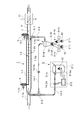
- Patent Document 2 for exhaust gas of a diesel engine in which the cyclone collecting means 132-1 is composed of two tangential cyclones 132-1a as schematically shown in FIG. 8 (A).
- An electrical processing device has been proposed previously.
- two tangential cyclones 132-1a are connected in parallel to the high-concentration exhaust gas outlet section 131-1b of the collection pipe 131-1 via communication pipes 135-1 and 135-2, and the cyclone trapping is performed.
- Exhaust pipes 136-1 and 136-2 for constituting the collecting means 132-1 and for joining the purified gas after passing through each tangential cyclone 132-1a to the low-concentration exhaust gas flowing in the low-concentration exhaust gas outlet pipe 133, respectively.
- this electric processing apparatus for exhaust gas is roughly divided into a tubular collection portion 131 that constitutes an electrostatic dust collection means and a separate collection 132 that constitutes a separate collection means, and collects PM particles.
- the tubular collecting part 131 provided for collecting is a collecting tube 131-1 having a collecting wall 131-1K having a predetermined length constituting the dust collecting electrode and a discharge electrode 131 for charging PM contained in the exhaust gas. -2.
- the collection pipe 131-1 constituting the dust collection electrode has an exhaust gas inlet 131-1a at the upstream (diesel engine side) end, and a PM low-concentration exhaust gas discharge pipe in the vicinity of the downstream axis.
- the discharge electrode 131-2 includes a main electrode 131-2a extending substantially over the entire length of the collection tube 131-1 constituting the dust collection electrode, and radially projecting electrode needles 131-2b spaced from the main electrode. It is composed of groups.
- the discharge electrode 131-2 configured in this manner is provided at the inlet portion of the seal air introduction pipe portion 131-1c provided on the exhaust gas inlet 131-1a side of the collection pipe 131-1 and the low concentration exhaust gas outlet pipe 133. Both ends of the main electrode 131-2a are supported via a support 134 that is suspended from the provided seal air introduction pipe portion 133-1.
- Reference numeral 137 denotes a flow control damper.
- FIG. 3 A tubular diesel engine exhaust gas treatment apparatus having a tubular collection part 141-1 and equipped with a cyclone-type separation and collection means for separating and collecting particulate matter separated from the tubular collection part 141-1.
- Cyclone collecting means 142-1 constituted by a tangential cyclone 142-1a is provided on the pipe from the high concentration exhaust gas deriving unit 141-1b of the particulate matter provided near the inner peripheral surface on the downstream side of the collecting unit 141-1.
- the high concentration exhaust gas flow discharged from the high concentration exhaust gas deriving unit 141-1b is introduced into the tangential cyclone 142-1a to collect and process large-diameter particles.
- the exhaust gas flow containing fine particles that could not be left is given kinetic energy by the blower 147 to increase and increase the pressure, and then pumped to the introduction pipe (exhaust pipe) 141-1a via the reflux pipe 142-2. ⁇ This is a method of refluxing.
- 141-1a is an exhaust gas inlet
- 141-1c and 143-1 are seal air introduction pipe sections
- 141-2a is a main electrode
- 141-2b is an electrode needle
- 143 is a low-concentration exhaust gas outlet pipe
- 144 is a main exhaust pipe
- the electrode support 148 is a flow control damper.
- oil concentration of the oily mixture when not diluted is 15 or less per million”.
- oil refers to crude oil, heavy oil and lubricating oil, “oiliness” is interpreted according to this meaning, and “oily mixture” refers to a mixture containing oil.
- Non-Patent Document 2 discloses a marine diesel engine that can reduce 80% of NOx from exhaust gas and remove nearly 100% of SOx from EGR gas by recirculating EGR gas diverted from exhaust gas to intake air. Has been.
- Non-Patent Document 3 describes an example of an SOx-compatible technology using Alfa Laval's output 21,000 kW, MANBW 2-stroke engine installed in the Danish Fikaria Seaways.
- a scrubber that uses both seawater and fresh water depending on the situation while using 2 percent heavy oil, sulfur in the exhaust gas, which is the required level scheduled for implementation in 2015 by the International Maritime Period (IMO)
- IMO International Maritime Period
- Exhaust gas treatment technology for diesel engine that electrically processes PM in exhaust gas by utilizing corona discharge or the like described in Patent Document 1 (for example, an electric treatment device for exhaust gas of diesel engine shown in FIG. 9) Has the following problems. That is, in the case of marine diesel engines, heavy oils [heavy oils] that have a significantly larger displacement and contain sulfur components at a higher concentration than diesel engines for automobiles that use light oils with a low sulfur content.
- FIG. 8 has a tangential cyclone 132-1a shown in FIG. 8 (A) as a separate collection unit 132, or a plurality of tangential cyclones having different processing capabilities, for example, FIG. 8 (B) uses a complex device consisting of three types of cyclones: small throughput tangential cyclone 132-1b, medium throughput tangential cyclone 132-1c, and high throughput tangential cyclone 132-1d. ing.
- reference numerals 138-1, 138-2, and 138-3 denote communication pipes
- 139-1, 139-2, and 139-3 denote flow control dampers, respectively.
- PM particles are reliably collected by each cyclone while controlling the flow rate of exhaust gas flowing into each cyclone to be optimal, and the low concentration of PM in the gas discharged from each cyclone is reliably reduced and diluted.
- the exhaust gas needs to be joined to the low concentration exhaust gas outlet pipe 133 through the exhaust gas exhaust pipes 136-1 and 136-2, and the engine and the exhaust gas treatment device are continuously operated as in the above-mentioned Patent Document 1.
- a processing unit for a large amount of collected PM that is expected by is not disclosed. *
- Non-Patent Document 1 emission control outside the special sea area, that is, prohibition of oil or oil mixture discharge to the ocean, etc. is established, and the oil content concentration of the oil mixture when not diluted The same applies to the case where PM is contained.
- Non-Patent Document 2 it is possible to reduce NOx by 80% from exhaust gas and remove SOx by nearly 100% from EGR gas by returning the EGR gas diverted from the exhaust gas to the intake air.
- the dust that passes through the scrubber and the sulfur content still contained in the PM will not only require a long-term actual ship test, but also the cleaning exhausted from the scrubber.
- the water should not affect the environment and ecosystem, especially dissolved and suspended in PM in the wash water of this scrubber, these environmental contaminant or ecological influence component due to the dissolution or the like of sO 2 Wastewater treatment such as removal and pH adjustment is expected to be a major problem. That is, even if PM is removed from the EGR gas, PM is not removed from the exhaust gas, and therefore there is no technical idea for processing the collected PM.
- the sulfur oxides in the exhaust gas are further washed in the scrubber tower.
- the water droplets in the gas are removed by a demister before being discharged from the chimney.
- the sulfur oxide remaining in the exhaust gas is further purified. Before discharging from the chimney of the ship, small water droplets are removed from the exhaust gas to prevent condensation and corrosion (removes 98% or more of the sulfur content of the exhaust gas).
- Non-Patent Document 3 on page 12, column 2, line 16 to column 3, line 1 "The scrubber can be said to be a large shower room installed in the funnel of a ship” and a photo on page 14
- Non-Patent Document 3 PM is not captured at all in the seawater mode (see the description on page 12, column 4, line 16 to column 5, line 1).
- an SCR system using a catalytic reaction is generally known as a known NOx reduction technique.
- the catalyst if the catalyst is activated when the exhaust gas temperature of the engine is sufficiently high and the catalyst surface is reliably exposed without being covered with soot or the like, the catalyst functions normally and high NOx. Reduction can be achieved.
- long stroke low speed engines are the mainstream compared to automobile engines, etc., in order to ensure an improvement in fuel consumption rate, and the energy of the combustion gas is slowly spent in the cylinder.
- the temperature of the exhaust gas becomes low due to the reliable removal of power as a motive power and the heat release associated with the contact of the combustion gas with the cylinder wall for a long time.
- the present invention has been made in view of the above-described problems of the prior art.
- high-speed and / or large-flow exhaust gas is discharged with a large displacement using a low-quality fuel such as heavy oil containing a sulfur component at a high concentration.
- the combustion exhaust gas generated at the time of incineration is returned to the collection tube and charged again.
- low-concentration exhaust gas is scrubbed with a PM fleece scrubber, or combustion exhaust gas generated during incineration is scrubbed with a PM fleece scrubber.
- Marine diesel using low quality fuel such as heavy oil containing sulfur component at high concentration, which can reliably collect and remove PM, and can be discharged as gas that can be environmentally protected by removing SOx. It is an object of the present invention to provide an engine exhaust gas treatment device.
- the exhaust gas treatment apparatus for a marine diesel engine that uses a low-quality fuel such as heavy oil containing a sulfur component at a high concentration is a marine diesel that uses a low-quality fuel such as heavy oil that contains a sulfur component at a high concentration.
- An engine exhaust gas treatment device has a discharge electrode for charging particulate matter contained in engine exhaust gas, and a tubular collecting portion of a predetermined length constituting a dust collecting electrode for collecting the charged particulate matter.
- the discharge electrode includes an electrostatic precipitator configured by a main electrode disposed in the tube axial direction in the tubular collecting portion and a plurality of radially projecting electrodes spaced from the main electrode.
- a low-concentration exhaust gas outlet pipe and a high-concentration exhaust gas outlet pipe, a PM fleece scrubber provided in the low-concentration exhaust gas outlet pipe, and particulate matter separated from the tubular collection part are separated by a dust collecting cyclone.
- a dust collecting means for collecting further having an incinerator for incinerating PM collected by the dust collecting means, and combustion exhaust gas generated by the incinerator in the collecting section or an exhaust pipe upstream of the collecting section
- a reflux pipe for refluxing is provided between the incinerator and an exhaust pipe upstream of the collection pipe or upstream of the collection section.
- the apparatus of the present invention is further provided with a return pipe for returning the combustion exhaust gas from the incinerator to the upstream side of the PM fleece scrubber provided in the low concentration exhaust gas outlet pipe, and a return pipe from the dust collecting cyclone, It is preferable that the PM combustion exhaust gas recirculation pipe is coupled, the lower part of the dust collecting cyclone is used as a PM storage stocker, and the PM incinerator is integrated with the lower part of the stocker via a shutter.
- the stocker controls a plurality of gas and scrubber treated water so that the PM can start incineration after the ship has advanced to the dischargeable sea area, a selective shutter is attached to the incinerator, and the shutter is opened and closed to control the time difference. So that it can be sequentially incinerated.
- the incinerator preferably uses a built-in heater (such as an electric heater) or a burner that has a function of heating and controlling the temperature by a controller to incinerate PM.
- the exhaust gas treatment apparatus for marine diesel engines that uses a low-quality fuel such as heavy oil containing a sulfur component at a high concentration has the following effects. That is, the PM in the exhaust gas of a marine diesel engine that emits high-speed and / or large-flow exhaust gas with a large displacement using a low-quality fuel such as heavy oil containing a sulfur component at a high concentration is converted into ESP / C / It is necessary to store all of the PM collected in the cyclone until the ship arrives at the port with the PM treatment facility as a port facility by incinerating the collected PM in the ship and collecting the collected PM.
- the treated water of PM fleece scrubber contains a high concentration of sulfur components but almost all organic solvent soluble components. Since it does not contain it, it has the effects of being able to be discharged into the ocean. In addition, as an incidental effect, it is the technique which can contribute to the improvement of the energy efficiency of the whole ship by collect
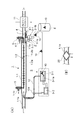
- FIG. 1 shows an apparatus according to a first embodiment of the present invention
- (A) is a schematic longitudinal sectional view showing the overall structure of the apparatus
- (B) shows an example of a structure in which an exhaust gas cooler is provided in an exhaust gas introduction pipe portion of the apparatus.
- It is a schematic longitudinal cross-sectional view.
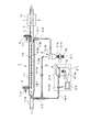
- It is a schematic longitudinal cross-sectional view which shows the whole structure of the 2nd Example apparatus of this invention.
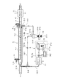
- It is a schematic longitudinal cross-sectional view which shows the whole structure of the 3rd Example apparatus of this invention.
- FIG. 1 It is a schematic longitudinal cross-sectional view which shows the whole structure of the 6th Example apparatus of this invention. It is the schematic which shows an example of the conventional diesel engine exhaust gas processing apparatus. Similarly, it is the schematic which shows the other example of the conventional diesel engine exhaust gas processing apparatus, A figure (A) is a whole block diagram, A figure (B) is the schematic which shows a cyclone collection means. It is the schematic which shows another example of the conventional diesel engine waste gas processing apparatus similarly.
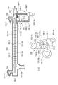
- the exhaust gas treatment device for a marine diesel engine shown as the first embodiment of the present invention is roughly divided into an electric dust collection unit 1, a separate collection unit 2, a PM incineration unit 3 and
- the electrostatic precipitator 1 is provided for collecting PM particles.
- the precipitator 1 has a predetermined length constituting the dust collecting electrode and the discharge electrode 1-2 for charging the PM contained in the exhaust gas.
- the collection pipe 1-1 constituting the dust collection electrode has an exhaust gas introduction pipe 1-1a at the end on the upstream side (diesel engine side), and a low concentration of PM in the vicinity of the axial center at the end on the downstream side.
- the exhaust gas outlet pipe 4 is provided with a PM high-concentration exhaust gas outlet portion 1-1b connected in the vicinity of the inner peripheral surface of the downstream end portion.
- the discharge electrode 1-2 is arranged at a predetermined interval in the longitudinal direction of the main electrode 1-2a extending substantially over the entire length around the axial center of the collection tube 1-1 constituting the dust collection electrode. And a group of radially protruding electrode needles 1-2b.
- the discharge electrode 1-2 configured as described above is provided at the inlet portion of the seal air introduction pipe portion 1-1c provided on the exhaust gas introduction pipe 1-1a side of the collection pipe 1-1 and the low concentration exhaust gas outlet pipe 4. Both ends of the main electrode 1-2a are supported through a support body 5 suspended from the provided seal air introduction pipe section 4-1.
- a PM fleece scrubber 11 that removes SOx contained in the exhaust gas but hardly removes PM is installed in the low-concentration exhaust gas outlet pipe 4 of PM10 by utilizing the difference in the diffusion speed of the gas and particles. SOx is removed from the gas.
- the scrubber-treated water removes SOx from the exhaust gas but hardly removes PM, so that it contains SOx but contains almost no PM and can be easily post-treated as waste treated water of scrubber-treated water.
- the discharge electrode 1-2 is supported at a desired interval by a stage (not shown) insulated from the inside of the collecting tube 1-1 as necessary. Further, the discharge electrode 1-2 is supplied with a controlled high voltage power source by being wired to a high voltage power source device (not shown) installed outside.
- the separation / collection unit 2 provided on the downstream side of the electric dust collection unit 1 in the flow direction of the exhaust gas is constituted by a cyclone collection unit 2-1 as a separation unit.
- the cyclone collecting means 2-1 is composed of a single tangential cyclone 2-1a connected to the high concentration exhaust gas deriving portion 1-1b of the collection pipe 1-1 through a communication pipe 5-1. Further, between the tangential cyclone 2-1a and the low concentration exhaust gas outlet pipe 4, the purified gas after passing through the tangential cyclone 2-1a is joined to the low concentration exhaust gas flowing in the low concentration exhaust gas outlet pipe 4.
- a discharge pipe 6-1 is provided.
- the low-concentration exhaust gas outlet pipe 4 is provided with a flow control damper 7 for adjusting the flow rate of the high-concentration exhaust gas flow rate and flow rate into the tangential cyclone 2-1a and the low-concentration exhaust gas discharge rate.
- the PM10 collected by the tangential cyclone 2-1a accumulates in a detachable hopper 2-1b provided immediately below the cone-shaped portion below the tangential cyclone 2-1a, and the hopper capacity limit is reached. If it reaches, replace it with a new hopper and store it.
- 8 is a stocker for storing PM10.
- the PM incineration unit 3 provided for incineration of PM comprises a PM incinerator 3-1 in which an incineration temperature, an exhaust gas flow rate, and the like are controlled by a controller 3-2, and an electric heater 3-1a is incorporated.
- 12a is a blower that imparts kinetic energy to the exhaust gas flow flowing in the reflux pipe 12. Further, the tip of the reflux pipe 12 is projected into the exhaust gas introduction pipe 1-1a in consideration of the ejector effect, and the tip opening is bent so as to be directed in the exhaust gas outflow direction.
- the PM incinerator 3-1 may be an incinerator using a burner (not shown) instead of the electric heater 3-1a.
- the PM combustion exhaust gas containing a high concentration of the sulfur component generated by incineration of PM10 is recirculated to the collection pipe 1-1 through the recirculation pipe 12 and mixed with the exhaust gas, and at the same time, this PM high concentration mixed flow gas Is led to the tangential cyclone 2-1a, and atmospheric exhaust gas containing a high concentration of sulfur components but a low concentration of PM10 is supplied to the PM fleece clubber 11.
- the PM fleece clubber 11 preserves the atmospheric environment as a gas in which PM remains in the atmospheric exhaust gas, but from which sulfur has been removed.
- the treated water of the PM fleece scrubber 11 contains a high concentration of sulfur components, but contains almost no PM, so it can be discharged to the ocean such as through a scrubber, and can be easily controlled with less man-hours and small size. Can be processed by a simple processing device.
- an exhaust gas cooler 20 is installed in the exhaust gas introduction pipe 1-1a as shown in FIG. 1B, and PM combustion exhaust gas is cooled by the exhaust gas cooling. You may make it recirculate
- FIG. When the exhaust gas cooler 20 is provided in the exhaust gas introduction pipe 1-1a to precool the exhaust gas, if the PM combustion exhaust gas is refluxed downstream of the exhaust gas cooler 20 of the exhaust gas introduction pipe 1-1a, a corrosive substance ( Since PM combustion exhaust gas containing sulfate combustion exhaust gas) does not flow into the exhaust gas cooler 20, it is not necessary to use a highly corrosion-resistant member as a member constituting the exhaust gas cooler 20, and it is inexpensive and durable. Easy to secure. When the PM combustion exhaust gas is recirculated upstream of the exhaust gas cooler 20, the total amount of the gas flowing into the collection pipe 1-1 can be precooled, so that it is high in the electric dust collection unit 1 and the separate collection unit 2. The collection rate can be secured.
- the exhaust gas treatment device for a marine diesel engine shown as the second embodiment of the present invention in FIG. 2 is a reflux type diesel engine exhaust gas treatment device and a PM incinerator using a cyclone of the first embodiment shown in FIG. 1 is charged to the particulate matter contained in the exhaust gas of a marine diesel engine that uses as a fuel a low-quality fuel such as heavy oil containing a sulfur component at a high concentration in the apparatus of the first embodiment shown in FIG. It has a discharge electrode 1-2 and a tubular collecting tube 1-1 that constitutes a dust collecting electrode that collects the charged particulate matter, and separates and captures the separated particulate matter from the tubular collecting tube 1-1.
- It has a cyclone-type separation / collection means 2-1 for collecting, and furthermore, the low concentration exhaust gas outlet pipe 4 of PM 10 removes SOx contained in the exhaust gas by utilizing the difference in diffusion speed of gas and particles, but removes PM.
- An inner peripheral surface on the downstream side of the tubular collection pipe 1-1 of a marine diesel engine exhaust gas treatment apparatus configured to remove the SOx from the exhaust gas released into the atmosphere by installing a PM fleece clubber 11 that is not removed at all.
- the high concentration exhaust gas pipe 5-2 from the PM high concentration exhaust gas deriving unit 1-1b provided in the vicinity is provided with a cyclone collecting means composed of a tangential cyclone 2-1a similar to the above, and the high concentration exhaust gas deriving unit
- a high-concentration exhaust gas stream discharged from 1-1b is introduced into a tangential cyclone 2-1a to collect and process large-diameter particles, and an exhaust gas stream containing fine-diameter particles that could not be removed by the cyclone,
- a system is used in which the exhaust gas is introduced into the exhaust gas introduction pipe 1-1a via the recirculation pipe 14-1, and is refluxed.
- a hopper 2-1b is provided immediately below the cone-shaped portion at the bottom of the tangential cyclone 2-1a, and a shutter for holding and dropping PM collected and accumulated in the hopper immediately below the hopper.
- a stocker 3'-1 having a larger internal volume than the hopper 2-1b also serving as a PM incinerator is provided via 2-1c.
- the stocker 3'-1 also serving as a PM incinerator has a built-in electric heater 3'-1a, and the controller 3-2 controls the incineration temperature, the flow rate of exhaust gas, and the like.
- the shutter 2-1c is opened and the stocker directly under the hopper PM is dropped into 3'-1, and then the shutter 2-1c is closed and stocked.
- Combustion exhaust gas from the stocker 3'-1 that also serves as a PM incinerator is configured to be returned to the exhaust gas introduction pipe 1-1a of the electric dust collector 1 through a return pipe 14-2.
- the leading ends of the reflux pipes 14-1 and 14-2 are projected into the exhaust gas introduction pipe 1-1a in consideration of the ejector effect in the same manner as described above, and the leading end openings are directed to the exhaust gas outflow direction.
- 14-1a and 14-2a are blowers that impart kinetic energy to the exhaust gas flows flowing through the reflux pipes 14-1 and 14-2, respectively. Needless to say, a burner (not shown) may be used in place of the electric heater 3'-1a.
- the high-concentration exhaust gas flow of PM that flows in the vicinity of the inner wall of the collection pipe downstream of the collection pipe 1-1 passes through the collection pipe 1-1.
- the high-concentration exhaust gas outlet 1-1b is introduced into the tangential cyclone 2-1a through the communication pipe 5-1 and the high-concentration exhaust gas pipe 5-2, and the large-diameter PM particles are centrifuged to form a lower cone-shaped part. Collected and deposited in the hopper 2-1b directly below.
- the generally purified exhaust gas stream containing fine PM particles not removed by the tangential cyclone 2-1a is 14-1 flows into the exhaust gas flow flowing in the exhaust gas introduction pipe 1-1a via the upstream communication pipe 5-3. At this time, the purified exhaust gas stream containing small-diameter PM particles is joined.
- kinetic energy is given by the blower 14-1a, and the pressure is increased / accelerated, and the gas is fed / refluxed to the exhaust gas introduction pipe 1-1a by the reflux pipe diameter 14-1.
- the low-concentration exhaust gas flow that flows in the vicinity of the axial center of the collection pipe 1-1 downstream of the collection pipe 1-1 is released to the atmosphere after removing SOx via the PM fleece scrubber 11. ing.
- PM collects and accumulates in the hopper 2-1b provided immediately below the cone-shaped portion below the tangential cyclone 2-1a of the PM incinerator, and when the hopper capacity limit is reached, the shutter 2-1c is installed. Open and drop the PM to drop into the stocker 3'-1 which also serves as a PM incinerator.
- the shutter 2-1c is closed, and the electric heater 3'-1a built in the stocker 3'-1 is burned and incinerated while controlling the incineration temperature, intake air amount, combustion exhaust gas flow rate, etc. by the controller 3-2. Further, the combustion exhaust gas from the PM incinerator is recirculated to the exhaust gas introduction pipe 1-1a of the electrostatic precipitator 1 through the recirculation pipe 14-1a2, so that it also serves as the PM incinerator, for example. Even if PM during combustion in the stocker 3'-1 rises temporarily, it will be reliably removed by going through the electrostatic precipitator 1 and separation / collector 2 again. Therefore, environmental preservation of atmospheric exhaust gas can be achieved.
- the exhaust gas stream (reflux gas) containing fine particles that passed through the cyclone 2-1a is recirculated, pumped, and mixed into the exhaust gas stream from the engine, and again discharged in the collection tube 1-1 ⁇ charge of particles ⁇ collection Adhesion to the inner wall surface of the tube ⁇ Particles can be made larger by repeated peeling, separated as a high-concentration exhaust gas stream, and reliably removed by the cyclone 2-1a.
- B The exhaust gas stream (reflux gas) containing fine particles that passed through the cyclone 2-1a is recirculated, pumped, and mixed into the exhaust gas stream from the engine, and again discharged in the collection tube 1-1 ⁇ charge of particles ⁇ collection Adhesion to the inner wall surface of the tube ⁇ Particles can be made larger by repeated peeling, separated as a high-concentration exhaust gas stream, and reliably removed by the cyclone 2-1a.
- the main engine in the marine engine is maintained or improved in the collection rate of the exhaust gas such as PM, that is, while maintaining or improving the cleanliness of the low concentration exhaust gas.
- the entire system without installing multiple tangential cyclones with different processing capacities in response to changes in operating conditions due to parallel operation or independent operation of auxiliary machines and exhaust gas flow rates that change according to the engine load factor Can be made compact and compact, and the control of the device is simplified, and the control software and device are simplified, making it inexpensive and highly reliable. (C).
- the blower 14-1a By installing the blower 14-1a, the purified exhaust gas stream containing fine PM particles can be smoothly passed through the exhaust gas introduction pipe 1-1a even if the exhaust gas flow resistance of the tangential cyclone 2-1a is somewhat large.
- the inflow tangential speed to the tangential cyclone 2-1a can be appropriately controlled, and the collection efficiency of the cyclone can be increased.
- the installation position of the blower 14-1a may be any position before or after the cyclone. When the blower installation position is upstream of the cyclone, the inflow tangential speed to the cyclone is kept high to easily obtain a high collection rate.
- the blower 14-1a is durable because the suction resistance of the blower 14-1a is large and surging is somewhat feared, but there is little adhesion of PM particles etc. to the fan blade surface and the gas temperature is lowered. Easy to secure.
- the front ends of the recirculation pipes 14-1 and 14-2 are projected into the exhaust gas introduction pipe 1-1a, and the front end opening thereof is bent so as to be directed in the exhaust gas outflow direction. Ejector effect is exerted by jetting the reflux with increased kinetic energy and increased pressure, and the exhaust gas flow flowing through the exhaust gas introduction pipe 1-1a is sucked to reduce exhaust resistance and increase engine efficiency. Can be measured.
- E E).
- the exhaust gas cooler 20 is installed in the exhaust gas introduction pipe 1-1a, and the PM combustion exhaust gas is recirculated downstream of the exhaust gas cooler 20. It goes without saying that this may be done.
- the exhaust gas treatment apparatus for a marine diesel engine shown as the third embodiment of the present invention in FIG. 3 is an electric dust collection section 1 for the combustion exhaust gas from the PM incineration section 3 of the second embodiment apparatus shown in FIG.
- the PM fleece scrubber 11 that is the same as the PM fleece scrubber 11 installed in the low-concentration exhaust gas outlet pipe 4 is installed in the recirculation pipe 14-2 that recirculates to the exhaust gas introduction pipe 1-1a. That is, the configuration is similar to the second embodiment apparatus shown in FIG. 2 in the particulate matter contained in the exhaust gas of marine diesel engines that use low quality fuel such as heavy oil containing a high concentration of sulfur component as fuel.
- It has a discharge electrode 1-2 to be charged and a tubular collecting tube 1-1 that constitutes a dust collecting electrode for collecting the charged particulate matter, and separates the separated particulate material from the tubular collecting tube 1-1.
- Separately collecting cyclone type collecting means 2-1 for collecting, and the low concentration exhaust gas outlet pipe 4 of PM10 removes SOx contained in the exhaust gas by utilizing the difference in diffusion speed of gas and particles, but PM PM fleece scrubber 11 is installed to remove SOx from the exhaust gas discharged to the atmosphere, and PM high concentration exhaust gas derived near the inner peripheral surface on the downstream side of the tubular collecting pipe 1-1 is derived.
- the high-concentration exhaust gas pipe 5-2 is provided with a cyclone collecting means composed of a tangential cyclone 2-1a similar to the above, and the high-concentration exhaust gas flow discharged from the high-concentration exhaust gas outlet 1-1b is tangentially connected.
- the large-diameter particles are collected and processed by introduction into the cyclone 2-1a, and an exhaust gas flow containing fine particles that could not be removed by the cyclone is passed through the reflux pipe 14-1 to the exhaust gas introduction pipe 1-1a. It is said to be a method of pumping and refluxing.
- the PM incineration unit 3 is provided with a hopper 2-1b directly below the cone-shaped portion at the bottom of the tangential cyclone 2-1a, and holds and drops the PM collected and accumulated in the hopper immediately below the hopper.
- a stocker 3'-1 having a larger internal volume than the hopper 2-1b also serving as a PM incinerator is provided via a shutter 2-1c.
- the stocker 3'-1 also serving as a PM incinerator has a built-in electric heater 3'-1a, and the controller 3-2 controls the incineration temperature, the intake air amount, the flow rate of combustion exhaust gas, etc. It has become.
- the shutter 2-1c is opened and the stocker directly under the hopper PM is dropped into 3'-1, and then the shutter 2-1c is closed and stocked.
- Combustion exhaust gas from the stocker 3'-1 that also serves as a PM incinerator is configured to be returned to the exhaust gas introduction pipe 1-1a of the electric dust collector 1 through a return pipe 14-2.
- the same PM fleece scrubber 11 as the PM fleece scrubber 11 installed in the low concentration exhaust gas outlet pipe 4 is installed in the reflux pipe 14-2.
- the 14-1a and 14-2a are blowers that impart kinetic energy to the exhaust gas flows flowing through the reflux pipes 14-1 and 14-2, respectively.
- the leading ends of the reflux pipes 14-1 and 14-2 are projected into the exhaust gas introduction pipe 1-1a in consideration of the ejector effect.
- the tip opening is bent so as to be directed in the exhaust gas outflow direction.
- the stocker 3'-1 which also serves as the PM incinerator may be an incinerator using a burner (not shown) instead of the electric heater 3'-1a.
- the stocker 3'- also serving as a PM incinerator. Since the sulfur component in the combustion exhaust gas can be removed in advance by the PM fleece scrubber 11 provided in the reflux pipe 14-2 for returning the combustion exhaust gas from 1 to the exhaust gas introduction pipe 1-1a, the corrosiveness to the main body and the cyclone is mild. The effect will be obtained.
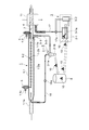
- the exhaust gas treatment apparatus for a marine diesel engine shown as the fourth embodiment of the present invention in FIG. 4 is a system for supplying a mixed flow of PM combustion exhaust gas and low concentration gas to the PM fleece clubber.
- the configuration is such that the flue gas recirculation pipe 12 from the PM incinerator 3-1 of the PM incinerator 3 of the first embodiment shown in FIG. It is made to project. That is, the configuration is similar to the first embodiment apparatus shown in FIG. 1 in the particulate matter contained in the exhaust gas of marine diesel engines that use low quality fuel such as heavy oil containing a high concentration of sulfur component as fuel.
- It has a discharge electrode 1-2 to be charged and a tubular collecting tube 1-1 that constitutes a dust collecting electrode for collecting the charged particulate matter, and separates the separated particulate material from the tubular collecting tube 1-1.
- Separately collecting cyclone type collecting means 2-1 for collecting, and the low concentration exhaust gas outlet pipe 4 of PM10 removes SOx contained in the exhaust gas by utilizing the difference in diffusion speed of gas and particles, but PM
- the PM fleece clubber 11 that removes almost all of the above is installed to remove SOx from the atmospheric exhaust gas, and the separate collection unit 2 provided downstream of the electric dust collection unit 1 in the flow direction of the exhaust gas, Separation Is constituted by a cyclone collecting means 2-1 as stage.
- the cyclone collecting means 2-1 is composed of a single tangential cyclone 2-1a connected to the high concentration exhaust gas deriving portion 1-1b of the collection pipe 1-1 through a communication pipe 5-1. Further, between the tangential cyclone 2-1a and the low concentration exhaust gas outlet pipe 4, the purified gas after passing through the tangential cyclone 2-1a is joined to the low concentration exhaust gas flowing in the low concentration exhaust gas outlet pipe 4.
- a discharge pipe 6-1 is provided, and the low-concentration exhaust gas outlet pipe 4 has a flow rate for adjusting the flow rate of the high-concentration exhaust gas flow rate and flow rate into the tangential cyclone 2-1a and the low-concentration exhaust gas discharge rate.
- a control damper 7 is provided.
- the PM incineration unit 3 provided for incinerating PM is controlled by the controller 3-2 with the incineration temperature, the intake air amount, the flow rate of the combustion exhaust gas, etc., and the electric heater 3-1a It consists of PM incinerator 3-1.
- a reflux pipe 15 is provided for returning the combustion exhaust gas from the PM incinerator 3-1 to the upstream side of the PM fleece scrubber 11 of the low concentration exhaust gas outlet pipe 4 of PM10.
- the reflux pipe 15 has its tip projecting into the low concentration exhaust gas outlet pipe 4.
- 15a is a blower that imparts kinetic energy to the exhaust gas flow flowing in the reflux pipe 15 as described above.
- the PM combustion exhaust gas containing a high concentration of sulfur components generated by incineration of PM 10 returns to the upstream side of the PM fleece scrubber 11 of the low concentration exhaust gas outlet pipe 4 through the reflux pipe 15 and is mixed with the PM low concentration exhaust gas. And supplied to the PM fleece clubber 11.
- the atmospheric exhaust gas becomes a gas in which the PM remains but the sulfur content is removed, and the atmospheric environment is preserved.
- the treated water of the PM fleece scrubber 11 contains a high concentration of sulfur components, but contains almost no PM, so it can be discharged to the ocean such as through a scrubber, and can be easily controlled with less man-hours and small size. Can be processed by a simple processing device.
- the exhaust gas treatment apparatus for a marine diesel engine shown as the fifth embodiment of the present invention in FIG. 5 is a system for supplying PM combustion exhaust gas directly to the PM fleece scrubber 11, and its configuration is high in concentration.
- Discharge electrode 1-2 for charging particulate matter contained in exhaust gas of marine diesel engine using low quality fuel such as heavy oil containing sulfur component as fuel, and dust collecting electrode for collecting charged particulate matter
- a cyclone-type separation / collection means 2-1 for separating and collecting particulate matter separated from the tubular collection tube 1-1, and further having a low concentration of PM10
- a PM fleece scrubber 11 that removes SOx contained in the exhaust gas but hardly removes PM is installed in the exhaust gas outlet pipe 4 by utilizing the difference in diffusion speed between gas and particles.
- the SOx is removed from the gas, and the separation / collection unit 2 provided on the downstream side of the electric dust collection unit 1 in the flow direction of the exhaust gas is constituted by a cyclone collection unit 2-1 as a separation unit.
- the cyclone collecting means 2-1 is a single tangential type connected to the high concentration exhaust gas deriving portion 1-1b of the collection pipe 1-1 through a communication pipe 5-1 and a high concentration exhaust gas pipe 5-2.
- the high-concentration exhaust gas flow which is composed of the cyclone 2-1a and is discharged from the high-concentration exhaust gas deriving unit 1-1b, is introduced into the tangential cyclone 2-1a to collect and process large-diameter particles and remove them with the same cyclone.
- the exhaust gas flow containing the fine particles that could not be produced is sent to the exhaust gas introduction pipe 1-1a via the reflux pipe 16 and refluxed.
- a blower 16 a imparts kinetic energy to the exhaust gas flow flowing in the reflux pipe 16.
- the PM incineration unit 3 provided for incineration of PM is controlled by the controller 3-2 in the same manner as described above, and the incineration temperature, the intake air amount, the flow rate of combustion exhaust gas, etc. are controlled, and the electric heater 3-1a is incorporated.
- PM incinerator 3-1 The apparatus of this embodiment is mainly characterized in that a reflux pipe 17 is provided for directly supplying the combustion exhaust gas from the PM incinerator 3-1 to the PM fleece scrubber 11 installed in the low concentration exhaust gas outlet pipe 4 of PM10. . 17a is a blower for imparting kinetic energy to the exhaust gas flow flowing in the reflux pipe 17, similar to the above.
- the PM low-concentration exhaust gas and the PM combustion exhaust gas supplied to the PM fleece scrubber 11 become a gas in which the PM remains but the sulfur content is removed, and the atmospheric environment is preserved.
- the treated water of the PM fleece scrubber 11 contains a high concentration of sulfur components, but contains almost no PM, so it can be discharged to the ocean such as through a scrubber, and can be easily controlled with less man-hours and small size. Can be processed by a simple processing device.
- corrosive PM combustion exhaust gas does not flow into the electric dust collection unit 1 and the separate collection unit 2, so members (collection tubes, electrodes, etc.) constituting them are not included. It is not necessary to use a highly corrosion resistant material, and it is inexpensive and easy to ensure durability.
- the exhaust gas treatment apparatus for a marine diesel engine shown as a sixth embodiment apparatus of the present invention in FIG. 6 is provided with a plurality of stockers that also serve as PM incinerators in the second embodiment apparatus shown in FIG. It is configured so that collection and alternate combustion can be performed. That is, the configuration is similar to the second embodiment apparatus shown in FIG. 2 in the particulate matter contained in the exhaust gas of marine diesel engines that use low quality fuel such as heavy oil containing a high concentration of sulfur component as fuel. It has a discharge electrode 1-2 to be charged and a tubular collecting tube 1-1 that constitutes a dust collecting electrode for collecting the charged particulate matter, and separates the separated particulate material from the tubular collecting tube 1-1.
- Part 1-1b The high-concentration exhaust gas pipe 5-2 is provided with a cyclone collecting means composed of a tangential cyclone 2-1a similar to the above, and the high-concentration exhaust gas flow discharged from the high-concentration exhaust gas outlet 1-1b is tangentially connected.
- the large-diameter particles are collected and processed by being introduced into the cyclone 2-1a, and an exhaust gas stream containing fine particles that cannot be removed by the cyclone is introduced into the introduction pipe 1-1a via the reflux pipe 14-1. It is said to be a method of pumping and refluxing.
- the PM incineration unit 3 is provided with a multi-branch pipe 2-1e such as a bifurcated part having a built-in switching valve 2-1d in a hopper 2-1b immediately below the cone-shaped part at the bottom of the tangential cyclone 2-1a.
- the inner volume of the pipe 2-1e is lower than that of the hopper 2-1b, which also serves as a PM incinerator, through a shutter 2-1c that holds and drops the PM collected and accumulated in the hopper 2-1b.
- a large stocker 3'-1 is provided.
- the stocker 3'-1 also serving as a PM incinerator has a built-in electric heater 3'-1a, and the controller 3-2 controls the incineration temperature, the intake air amount, the flow rate of combustion exhaust gas, etc. It has become.
- the shutter 2-1c is opened and the stocker directly under the hopper PM is dropped into 3'-1, and then the shutter 2-1c is closed and stocked.
- Combustion exhaust gas from the stocker 3-1 that also serves as a PM incinerator is configured to be returned to the exhaust gas introduction pipe 1-1a of the electric dust collector 1 through a return pipe 14-2.
- the leading ends of the reflux pipes 14-1 and 14-2 are projected into the exhaust gas introduction pipe 1-1a in consideration of the ejector effect.
- the tip opening is bent so as to be directed in the exhaust gas outflow direction.
- the stocker 3'-1 which also serves as the PM incinerator may be an incinerator using a burner (not shown) instead of the electric heater 3'-1a.
Abstract
Description
即ち、本願出願人は特許文献1において、図7にその概略を示すように、排気ガス通路121にコロナ放電部122-1と帯電部122-2とからなる放電帯電部122を設けて、コロナ放電された電子129を排気ガスG1中のカーボンを主体とするPM128に帯電させ、同排気ガス通路121に配置した捕集板123で前記帯電したPM128を捕集する方式であって、放電帯電部122における電極針124は排気ガス流の流れ方向長さが短く、かつ捕集板123は排気ガス流の流れ方向に対し直角方向に配設された構成となしたディーゼルエンジンの排気ガス用電気式処理装置を先に提案している。なお図中、125はシールガス管、126は高圧電源装置、127は排気ガス誘導管である。 For example, methods and apparatuses described below (
That is, the applicant of the present application disclosed in
なお、ここで「油」とは、原油、重油及び潤滑油を言い、「油性」とは、この意味に従って解釈するものとし、「油性混合物」とは、油を含有する混合物をいう。 On the other hand, the 15th regulation “Oil Emission Regulation” of Part C “Oil Emission Regulation” in
Here, “oil” refers to crude oil, heavy oil and lubricating oil, “oiliness” is interpreted according to this meaning, and “oily mixture” refers to a mixture containing oil.
即ち、船舶用ディーゼルエンジンにあっては、硫黄成分の含有量の少ない軽油を使用する自動車用ディーゼルエンジンと比較して格段に大きな排気量を有しかつ高濃度に硫黄成分を含有する重油[重油は軽油に対し500~3500倍程度の硫黄分を含有:JIS K2204:2007「軽油」;0.0010質量%以下、K2205-1990「重油」;0.5~3.5質量%以下、による]等の低質燃料を使用する大排気量船舶用ディーゼルエンジンに、例えば先の特許文献1に記載の排気ガス浄化装置を用いた場合には、高濃度に硫黄成分を含有する重油等の低質燃料中の硫黄成分が排気ガスやEGRガス中にSOFとして含まれるだけでなくサルフェートとなりエンジン構成部品、特に排気関係部品を腐食するという課題を克服する必要があると共に、硫黄成分に基づくSOxが全く捕集できず、さらに連続してエンジン及び排気ガス用電気式処理装置を運転することにより予想される捕集した大量のPMの処理部は開示されていない。 Exhaust gas treatment technology for diesel engine that electrically processes PM in exhaust gas by utilizing corona discharge or the like described in Patent Document 1 (for example, an electric treatment device for exhaust gas of diesel engine shown in FIG. 9) Has the following problems.
That is, in the case of marine diesel engines, heavy oils [heavy oils] that have a significantly larger displacement and contain sulfur components at a higher concentration than diesel engines for automobiles that use light oils with a low sulfur content. Contains about 500 to 3,500 times the sulfur content of diesel oil: JIS K2204: 2007 “Diesel oil”; 0.0010 mass% or less, K2205-1990 “Heavy oil”; 0.5 to 3.5 mass% or less] For example, when the exhaust gas purification device described in
要約(I)技術的背景:
(I)IMOは船舶による汚染に対する規制を強化します
(ア)硫黄酸化物(SOx)(新造船及び既存船両方に適用)
燃料油の硫黄濃度の上限を定める世界的な規制が適用されます。厳格化された規制が排出規制海域に適用されます。上限値は2012年から段階的に変更されます。この規制値に適合するためには、低硫黄燃料の使用や排ガス浄化装置が必要です。
(イ)窒素酸化物(NOx)(新造船のみに適用)
既存の規制要求事項は、出力130KW以上の舶用ディーゼル機関に適用されます。船舶の建造日に応じて異なる規制値が適用されます。排出規制海域を航行する新造船に対して、2016年より厳格化された規制(Tier III)が適用されます。
(ウ)ビルジ水(新造船及び既存船両方に適用)
船外に排出するビルジ水の規制値は15ppmです。
要約(II)水処理技術:
(II)アルファ・ラバルの水処理技術:
(ア)船舶のビルジタンクの油性廃水のみを処理するPureBilgeソリューションは、一段階の高速遠心分離システムによって、化学物質や吸着フィルタ、膜を使用せずに大量の水を浄化し、水中油分は5ppm未満となります。
(イ)IMOが船舶に要求するNOx排出の80パーセント削減を可能にするために、アルファ・ラバルはMANディーゼル社と協力して大型2ストロークディーゼルエンジン用の排気再循環(EGR)システムを開発しました。
(ウ)SOx排出については、アルファ・ラバルが完全な排ガス浄化プロセスを開発しました。現在船上での試験が行われているこのシステムでもアルファ・ラバル分離機を使用して、スクラバーからの汚水を海への排水前に浄化しています。
要約(III)SOx対応技術:
(III)アルファ・ラバルのSOx対応技術:
(フィカリア・シーウェイズ号(デンマーク)=出力21,000kW,MAN B&W2ストロークエンジン)に搭載
(ア)燃料は硫黄含有率2.2パーセントの重油で、排出ガスは、2015年に施行されるIMO(国際海事機関)の要求レベルである硫黄含有率0.1パーセントと同等のレベルまで洗浄除去されています。
(イ)アルファ・ラバルのPureSOxは、海水と清水の双方を状況に応じて使い分ける。
「海水あるいは淡水を苛性ソーダと水溶液を使って主機の排ガスを洗浄します」
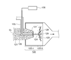
●第一段階では、ガス導入部分で水を噴射する事によって排ガスを冷却し、そして排ガス中の煤塵の大半もここで除去されます。
●第二段階では、スクラバタワー内で排ガス中の硫黄酸化物等をさらに洗浄します。排ガス中の水滴の持ち去りや腐食を防止する為に、煙突から排出される前にガス中の水滴はデミスターで除去されます。
●第三段階では、排ガスに残留している硫黄酸化物をさらに浄化します。船舶の煙突から排出する前に、凝縮や腐食を防ぐために、排ガスから小さな水滴が除去されます(排ガスの硫黄分を98%以上除去)。 In the “Clean Solution Wave” described in
Summary (I) Technical background:
(I) IMO will strengthen regulations on ship pollution (a) Sulfur oxide (SOx) (applicable to both new ships and existing ships)
Global regulations governing the upper limit of fuel oil sulfur concentration apply. Stricter regulations apply to seas where emissions are restricted. The upper limit will be changed gradually from 2012. In order to comply with this regulation value, the use of low sulfur fuel and exhaust gas purification equipment are required.
(B) Nitrogen oxide (NOx) (applicable only to new ships)
Existing regulatory requirements apply to marine diesel engines with an output of more than 130KW. Different regulatory values apply depending on the ship construction date. Stricter regulations (Tier III) will be applied to new ships navigating emission-controlled sea areas from 2016.
(C) Bilge water (applicable to both new ships and existing ships)
The limit value of bilge water discharged out of the ship is 15 ppm.
Summary (II) Water Treatment Technology:
(II) Alfa Laval water treatment technology:
(A) The PureBilge solution that processes only oily wastewater from ship bilge tanks purifies a large amount of water without using chemicals, adsorption filters, or membranes by a one-stage high-speed centrifuge system, and the oil content in water is less than 5 ppm. It becomes.
(B) To enable 80% reduction in NOx emissions required by IMO for ships, Alfa Laval has developed an exhaust gas recirculation (EGR) system for large two-stroke diesel engines in cooperation with MAN Diesel. did.
(C) For SOx emissions, Alfa Laval has developed a complete exhaust gas purification process. This system, which is currently being tested on board, uses an Alfa Laval separator to purify the sewage from the scrubber before draining it into the sea.
Summary (III) SOx technology:
(III) Alfa Laval's SOx technology:
(Ficaria Seaways (Denmark) = Output 21,000 kW, MAN B & W 2-stroke engine) (A) Fuel is heavy oil with a sulfur content of 2.2%, and the exhaust gas is IMO ( Washed and removed to a level equivalent to the 0.1% sulfur content required by the International Maritime Organization).
(A) Alfa Laval PureSOx uses both seawater and fresh water depending on the situation.
“The main engine exhaust gas is washed with seawater or fresh water using caustic soda and aqueous solution.”
● In the first stage, the exhaust gas is cooled by injecting water at the gas introduction part, and most of the dust in the exhaust gas is also removed here.
● In the second stage, the sulfur oxides in the exhaust gas are further washed in the scrubber tower. In order to prevent the removal of water droplets in the exhaust gas and corrosion, the water droplets in the gas are removed by a demister before being discharged from the chimney.
● In the third stage, the sulfur oxide remaining in the exhaust gas is further purified. Before discharging from the chimney of the ship, small water droplets are removed from the exhaust gas to prevent condensation and corrosion (removes 98% or more of the sulfur content of the exhaust gas).
なお、焼却装置は内蔵された加熱用ヒーター(電気ヒーター等)もしくはバーナーがコントローラにより昇温・加熱制御されてPMが焼却される機能を有するものを用いるのが好ましい。 Further, the stocker controls a plurality of gas and scrubber treated water so that the PM can start incineration after the ship has advanced to the dischargeable sea area, a selective shutter is attached to the incinerator, and the shutter is opened and closed to control the time difference. So that it can be sequentially incinerated.
The incinerator preferably uses a built-in heater (such as an electric heater) or a burner that has a function of heating and controlling the temperature by a controller to incinerate PM.
即ち、特に高濃度に硫黄成分を含有する重油等の低質燃料を使用する大排気量で高速及び/又は大流量の排気ガスが排出される舶用ディーゼルエンジンの排気ガス中のPMをESP/C/PDFにて捕集し、捕集したPMを船内で焼却処理することにより、船が港湾設備としてPM処理施設のある港に着くまでサイクロンで捕集したPMの全てを船内に貯蔵しておく必要がなく、よって船内に貯蔵のための大きなスペースを必要としないこと、船室が減少することなく、積み荷を減少させることもないので経費の増大を抑制できること、又、好ましくは、焼却時に発生する燃焼排気ガスを捕集管に還流して再度帯電・付着・凝集・濃縮により確実に捕集すると共に、低濃度排出ガスをPMフリースクラバーにてスクラバー処理することにより大気排出ガスからSOxを確実に除去して環境保全可能なガスとして排出することができること、さらにPMフリースクラバーの処理水は、硫黄成分は高濃度に含有しているが有機溶剤可溶成分をほとんど含有していないので海洋排出が可能であること、等の作用効果を奏する。なお付随的な効果としては、PMを焼却したガスより熱エネルギーを回収することにより船全体としてのエネルギー効率の向上にも寄与し得る技術である。 The exhaust gas treatment apparatus for marine diesel engines that uses a low-quality fuel such as heavy oil containing a sulfur component at a high concentration according to the present invention has the following effects.
That is, the PM in the exhaust gas of a marine diesel engine that emits high-speed and / or large-flow exhaust gas with a large displacement using a low-quality fuel such as heavy oil containing a sulfur component at a high concentration is converted into ESP / C / It is necessary to store all of the PM collected in the cyclone until the ship arrives at the port with the PM treatment facility as a port facility by incinerating the collected PM in the ship and collecting the collected PM. Therefore, it does not require a large space for storage in the ship, can suppress the increase in cost because the cabin is not reduced, and the load is not reduced, and preferably the combustion that occurs at the time of incineration By recirculating the exhaust gas to the collection tube and collecting it again by charging, adhesion, aggregation and concentration, and scrubbing the low concentration exhaust gas with a PM fleece scrubber SOx can be reliably removed from the exhaust gas and discharged as an environmentally safe gas. Furthermore, the treated water of PM fleece scrubber contains a high concentration of sulfur components but almost all organic solvent soluble components. Since it does not contain it, it has the effects of being able to be discharged into the ocean. In addition, as an incidental effect, it is the technique which can contribute to the improvement of the energy efficiency of the whole ship by collect | recovering thermal energy from the gas which incinerated PM.
なお、スクラバー処理水は、排気ガスからSOxは除去するがPMをほとんど除去しないのでSOxは含有するがPMをほとんど含有せずスクラバー処理水の廃棄処理水としての後処理は容易である。又、放電電極1-2は必要に応じ捕集管1-1の内部より絶縁されたステ―(図示せず)により所望間隔を有して支持されている。さらに、この放電電極1-2は外部に設置された高圧電源装置(図示せず)に配線されて制御された高圧電源の供給を受けている。 1 (A) and 1 (B), the exhaust gas treatment device for a marine diesel engine shown as the first embodiment of the present invention is roughly divided into an electric
The scrubber-treated water removes SOx from the exhaust gas but hardly removes PM, so that it contains SOx but contains almost no PM and can be easily post-treated as waste treated water of scrubber-treated water. The discharge electrode 1-2 is supported at a desired interval by a stage (not shown) insulated from the inside of the collecting tube 1-1 as necessary. Further, the discharge electrode 1-2 is supplied with a controlled high voltage power source by being wired to a high voltage power source device (not shown) installed outside.
なお、接線式サイクロン2-1aにて集塵されるPM10は前記接線式サイクロン2-1a下部のコーン状部分直下に設けられた着脱可能なホッパー2-1b内に堆積してゆき、ホッパー容量限界に達した場合は新たなホッパーに順次交換し保管する。図中、8はPM10を貯蔵するストッカーである。 The separation /
The PM10 collected by the tangential cyclone 2-1a accumulates in a detachable hopper 2-1b provided immediately below the cone-shaped portion below the tangential cyclone 2-1a, and the hopper capacity limit is reached. If it reaches, replace it with a new hopper and store it. In the figure, 8 is a stocker for storing PM10.
(イ).サイクロン2-1aを通過した細径粒子を含む排ガス流(還流ガス)をエンジンからの排気ガス流へ還流・圧送・混合させて捕集管1-1で再度、放電→粒子の帯電→捕集管内壁面への付着→剥離の繰返しにより大径粒子化させ、高濃度排ガス流として分離しサイクロン2-1aで確実に除去することができる。
(ロ).サイクロン2-1a後の排ガス流を還流させることにより、排出されるガスのPMなどの捕集率を維持もしくは向上、即ち、低濃度排出ガスの清浄度を維持もしくは向上させながら、舶用エンジンにおける主機及び補機の並列運転や単独運転に伴う運転状況の変化やエンジンの負荷率に応じて変化する排気ガス流量に対応して処理能力の異なる各接線式サイクロンを複数台設置することもなく装置全体を小型・コンパクトにできると共に装置の制御もシンプルとなり制御ソフト・装置も単純となり安価で信頼性の高いものとなる。
(ハ).ブロアー14-1aの設置により、例え接線式サイクロン2-1aの排気ガス流の流過抵抗が多少大きくても細径のPM粒子を含有する浄化された排ガス流をスムーズに排ガス導入管1-1aに還流できるのみならず、接線式サイクロン2-1aへの流入接線速度を適正に制御でき同サイクロンでの捕集効率も上昇する。なお、ブロアー14-1aの設置位置は、サイクロン前後の何れの位置でもよく、ブロアー設置位置がサイクロン上流側の場合はサイクロンへの流入接線速度を高く維持して高い捕集率を得易く、他方、サイクロン下流側の場合はブロアー14-1aの吸引抵抗が大きくサージングが多少危惧されるもののファンブレード表面へのPM粒子などの付着が少なくかつガスの温度が低下しているのでブロアー14-1aは耐久性を確保し易い。
(ニ).還流配管14-1、14-2の配管先端部を排ガス導入管1-1a内に突出させ、かつその先端開口部は排気ガス流出方向を指向するように屈曲させて、ブロアー14-1aにて運動エネルギーを付与され昇圧・増速した還流を噴出させることによりエジェクター効果を発揮させ、排ガス導入管1-1aを流れて来る排気ガス流を吸引させることにより排気抵抗を減少させてエンジン効率の上昇をはかることができる。
(ホ).船内でPMを焼却することにより長期にわたる連続航海ができる。
(へ).焼却炉排ガスを捕集管上流に還流することにより焼却炉排ガス内のPMを確実に除去できる。
(ト).PMフリースクラバー11を設けたことにより排出ガスからSOxを除去できる。なお、PMフリースクラバー11の処理水は、硫黄成分は高濃度に含有しているがPMをほとんど含有していないのでスクラバースルーなどの海洋排出が可能であったり、少ない工数及び小型で制御が簡易な処理装置で処理ができる。 According to the exhaust gas processing apparatus having the configuration shown in FIG. 2, the following operational effects can be obtained.
(I). The exhaust gas stream (reflux gas) containing fine particles that passed through the cyclone 2-1a is recirculated, pumped, and mixed into the exhaust gas stream from the engine, and again discharged in the collection tube 1-1 → charge of particles → collection Adhesion to the inner wall surface of the tube → Particles can be made larger by repeated peeling, separated as a high-concentration exhaust gas stream, and reliably removed by the cyclone 2-1a.
(B). By recirculating the exhaust gas flow after the cyclone 2-1a, the main engine in the marine engine is maintained or improved in the collection rate of the exhaust gas such as PM, that is, while maintaining or improving the cleanliness of the low concentration exhaust gas. The entire system without installing multiple tangential cyclones with different processing capacities in response to changes in operating conditions due to parallel operation or independent operation of auxiliary machines and exhaust gas flow rates that change according to the engine load factor Can be made compact and compact, and the control of the device is simplified, and the control software and device are simplified, making it inexpensive and highly reliable.
(C). By installing the blower 14-1a, the purified exhaust gas stream containing fine PM particles can be smoothly passed through the exhaust gas introduction pipe 1-1a even if the exhaust gas flow resistance of the tangential cyclone 2-1a is somewhat large. In addition to being able to recirculate, the inflow tangential speed to the tangential cyclone 2-1a can be appropriately controlled, and the collection efficiency of the cyclone can be increased. The installation position of the blower 14-1a may be any position before or after the cyclone. When the blower installation position is upstream of the cyclone, the inflow tangential speed to the cyclone is kept high to easily obtain a high collection rate. In the case of the downstream side of the cyclone, the blower 14-1a is durable because the suction resistance of the blower 14-1a is large and surging is somewhat feared, but there is little adhesion of PM particles etc. to the fan blade surface and the gas temperature is lowered. Easy to secure.
(D). The front ends of the recirculation pipes 14-1 and 14-2 are projected into the exhaust gas introduction pipe 1-1a, and the front end opening thereof is bent so as to be directed in the exhaust gas outflow direction. Ejector effect is exerted by jetting the reflux with increased kinetic energy and increased pressure, and the exhaust gas flow flowing through the exhaust gas introduction pipe 1-1a is sucked to reduce exhaust resistance and increase engine efficiency. Can be measured.
(E). Long-term continuous navigation is possible by incinerating PM on board.
(What). By returning the incinerator exhaust gas to the upstream of the collection tube, PM in the incinerator exhaust gas can be reliably removed.
(G). By providing the
即ち、その構成は、図2に示す第2実施例装置と同様に、高濃度に硫黄成分を含有する重油等の低質燃料を燃料として使用する船舶用ディーゼルエンジンの排ガス中に含まれる粒状物質に帯電させる放電電極1-2、及び帯電された前記粒状物質を捕集する集塵電極を構成する管状捕集管1-1を有し、管状捕集管1-1から剥離した粒状物質を分別して捕集するサイクロン方式の分別捕集手段2-1を備え、さらにPM10の低濃度排ガス導出管4にガスと粒子の拡散速度の相違を利用して排気ガスに含まれるSOxは除去するがPMをほとんど除去しないPMフリースクラバー11を設置して大気放出排気ガスからSOxを除去させる構成となし、前記管状捕集管1-1の下流側の内周面付近に設けたPMの高濃度排ガス導出部1-1bからの高濃度排ガス配管5-2に、前記と同様の接線式サイクロン2-1aで構成したサイクロン捕集手段を設け、高濃度排ガス導出部1-1bより排出される高濃度排ガス流を接線式サイクロン2-1aに導入して大径粒子を捕集・処理するとともに、同サイクロンで除去できなかった細径粒子を含有する排ガス流を還流配管14-1を経由して排ガス導入管1-1aに圧送・還流させる方式となしている。 The exhaust gas treatment apparatus for a marine diesel engine shown as the third embodiment of the present invention in FIG. 3 is an electric
That is, the configuration is similar to the second embodiment apparatus shown in FIG. 2 in the particulate matter contained in the exhaust gas of marine diesel engines that use low quality fuel such as heavy oil containing a high concentration of sulfur component as fuel. It has a discharge electrode 1-2 to be charged and a tubular collecting tube 1-1 that constitutes a dust collecting electrode for collecting the charged particulate matter, and separates the separated particulate material from the tubular collecting tube 1-1. Separately collecting cyclone type collecting means 2-1 for collecting, and the low concentration exhaust
なお、本実施例装置も前記図2に示す第2実施例装置と同様に、還流配管14-1、14-2の先端部はエジェクター効果を考慮して排ガス導入管1-1a内に突出させ、かつ先端開口部は排気ガス流出方向を指向するように屈曲させる。又、前記PM焼却炉を兼ねたストッカー3´-1は、電気ヒーター3´-1aに代えて、バーナ(図示せず)を用いた焼却炉でもよいことはいうまでもない。 On the other hand, the
Incidentally, in the present embodiment apparatus, similarly to the second embodiment apparatus shown in FIG. 2, the leading ends of the reflux pipes 14-1 and 14-2 are projected into the exhaust gas introduction pipe 1-1a in consideration of the ejector effect. The tip opening is bent so as to be directed in the exhaust gas outflow direction. Needless to say, the stocker 3'-1 which also serves as the PM incinerator may be an incinerator using a burner (not shown) instead of the electric heater 3'-1a.
即ち、その構成は、図1に示す第1実施例装置と同様に、高濃度に硫黄成分を含有する重油等の低質燃料を燃料として使用する船舶用ディーゼルエンジンの排ガス中に含まれる粒状物質に帯電させる放電電極1-2、及び帯電された前記粒状物質を捕集する集塵電極を構成する管状捕集管1-1を有し、管状捕集管1-1から剥離した粒状物質を分別して捕集するサイクロン方式の分別捕集手段2-1を備え、さらにPM10の低濃度排ガス導出管4にガスと粒子の拡散速度の相違を利用して排気ガスに含まれるSOxは除去するがPMをほとんど除去しないPMフリースクラバー11を設置して大気放出排気ガスからSOxを除去させる構成となし、前記排ガスの流れ方向における電気集塵部1の下流側に設けられた分別捕集部2は、分別手段としてのサイクロン捕集手段2-1により構成されている。このサイクロン捕集手段2-1は、捕集管1-1の高濃度排ガス導出部1-1bに連通管5-1を介して接続された1台の接線式サイクロン2-1aで構成され、さらに該接線式サイクロン2-1aと前記低濃度排ガス導出管4との間に、接線式サイクロン2-1a通過後の浄化ガスを低濃度排ガス導出管4内を流れる低濃度排ガスに合流させるための排出管6-1を配設し、前記低濃度排ガス導出管4には、接線式サイクロン2-1aへの高濃度排ガス流入量及び流入速度と低濃度排ガス放出量の流量調整を行うための流量制御ダンパ7を設けている。 The exhaust gas treatment apparatus for a marine diesel engine shown as the fourth embodiment of the present invention in FIG. 4 is a system for supplying a mixed flow of PM combustion exhaust gas and low concentration gas to the PM fleece clubber. The configuration is such that the flue
That is, the configuration is similar to the first embodiment apparatus shown in FIG. 1 in the particulate matter contained in the exhaust gas of marine diesel engines that use low quality fuel such as heavy oil containing a high concentration of sulfur component as fuel. It has a discharge electrode 1-2 to be charged and a tubular collecting tube 1-1 that constitutes a dust collecting electrode for collecting the charged particulate matter, and separates the separated particulate material from the tubular collecting tube 1-1. Separately collecting cyclone type collecting means 2-1 for collecting, and the low concentration exhaust
即ち、その構成は、図2に示す第2実施例装置と同様に、高濃度に硫黄成分を含有する重油等の低質燃料を燃料として使用する船舶用ディーゼルエンジンの排ガス中に含まれる粒状物質に帯電させる放電電極1-2、及び帯電された前記粒状物質を捕集する集塵電極を構成する管状捕集管1-1を有し、管状捕集管1-1から剥離した粒状物質を分別して捕集するサイクロン方式の分別捕集手段2-1を備え、さらにPM10の低濃度排ガス導出管4にガスと粒子の拡散速度の相違を利用して排気ガスに含まれるSOxは除去するがPMをほとんど除去しないPMフリースクラバー11を設置して大気放出排気ガスからSOxを除去させる構成となし、前記管状捕集管1-1の下流側の内周面付近に設けたPMの高濃度排ガス導出部1-1bからの高濃度排ガス配管5-2に、前記と同様の接線式サイクロン2-1aで構成したサイクロン捕集手段を設け、高濃度排ガス導出部1-1bより排出される高濃度排ガス流を接線式サイクロン2-1aに導入して大径粒子を捕集・処理するとともに、同サイクロンで除去できなかった細径粒子を含有する排ガス流を、還流配管14-1を経由して導入管1-1aに圧送・還流させる方式となしている。 The exhaust gas treatment apparatus for a marine diesel engine shown as a sixth embodiment apparatus of the present invention in FIG. 6 is provided with a plurality of stockers that also serve as PM incinerators in the second embodiment apparatus shown in FIG. It is configured so that collection and alternate combustion can be performed.
That is, the configuration is similar to the second embodiment apparatus shown in FIG. 2 in the particulate matter contained in the exhaust gas of marine diesel engines that use low quality fuel such as heavy oil containing a high concentration of sulfur component as fuel. It has a discharge electrode 1-2 to be charged and a tubular collecting tube 1-1 that constitutes a dust collecting electrode for collecting the charged particulate matter, and separates the separated particulate material from the tubular collecting tube 1-1. Separately collecting cyclone type collecting means 2-1 for collecting, and the low concentration exhaust
なお、本実施例装置も前記図2に示す第2実施例装置と同様に、還流配管14-1、14-2の先端部はエジェクター効果を考慮して排ガス導入管1-1a内に突出させ、かつ先端開口部は排気ガス流出方向を指向するように屈曲させる。又、前記PM焼却炉を兼ねたストッカー3´-1は、電気ヒーター3´-1aに代えて、バーナ(図示せず)を用いた焼却炉でもよいことはいうまでもない。 On the other hand, the
Incidentally, in the present embodiment apparatus, similarly to the second embodiment apparatus shown in FIG. 2, the leading ends of the reflux pipes 14-1 and 14-2 are projected into the exhaust gas introduction pipe 1-1a in consideration of the ejector effect. The tip opening is bent so as to be directed in the exhaust gas outflow direction. Needless to say, the stocker 3'-1 which also serves as the PM incinerator may be an incinerator using a burner (not shown) instead of the electric heater 3'-1a.
1-1 捕集管
1-1a 排ガス導入管
1-1b 高濃度排ガス導出部
1-1c、4-1 シールエアー導入管部
1-2 放電電極
1-2a 主電極
1-2b 電極針
2 分別捕集部
2-1 サイクロン捕集手段
2-1a 接線式サイクロン
2-1b ホッパー
2-1c シャッター
2-1d 切換え弁
2-1e 多数分岐管
3 PM焼却部
3-1 PM焼却炉
3-1a、3´-1a 電気ヒーター
3´-1 PM焼却炉を兼ねたストッカー
3-2 コントローラ
4 低濃度排ガス導出管
5 支持体
5-1、5-3 連通管
5-2 高濃度排ガス配管
6-1 排出管
7 流量制御ダンパ
8 ストッカー
11 PMフリースクラバー
10 PM
12、14-1、14-2、15、16、17 還流配管
12a、14-1a、14-2a、15a、16a、17a ブロアー
20 排気ガス冷却器 DESCRIPTION OF
12, 14-1, 14-2, 15, 16, 17
Claims (4)
- 高濃度に硫黄成分を含有する重油等の低質燃料を使用する船舶用ディーゼルエンジンの排気ガス浄化装置において、エンジンの排ガス中に含まれる粒状物質に帯電させる放電電極、及び帯電された前記粒状物質を捕集する集塵電極を構成する所定長さの管状捕集部を有し、かつ前記放電電極は前記管状捕集部内に管軸方向に配設された主電極と該主電極に間隔配設された放射状に突出する複数の電極とによって構成された電気集塵手段と、低濃度排ガス導出管及び高濃度排ガス導出管と、前記低濃度排ガス導出管に設けたPMフリースクラバーと、前記管状捕集部から剥離した粒状物質を集塵用サイクロンにて分別して捕集する集塵手段を備え、さらに該集塵手段によって集塵したPMを焼却する焼却装置を有し、かつ前記焼却装置で生じる燃焼排ガスを前記捕集部もしくは捕集部上流の排気管に還流する還流配管を前記焼却装置と捕集管上流もしくは前記捕集部上流の排気管の間に配設した構成となしたことを特徴とする、高濃度に硫黄成分を含有する重油等の低質燃料を使用する船舶用ディーゼルエンジンの排気ガス処理装置。 In an exhaust gas purification apparatus for a marine diesel engine that uses a low-quality fuel such as heavy oil containing a sulfur component at a high concentration, a discharge electrode for charging particulate matter contained in the exhaust gas of the engine, and the charged particulate matter It has a tubular collecting portion of a predetermined length that constitutes a dust collecting electrode to be collected, and the discharge electrode is disposed in the tubular collecting portion in the tube axis direction and spaced from the main electrode An electrostatic precipitating means comprising a plurality of radially projecting electrodes, a low concentration exhaust gas outlet tube and a high concentration exhaust gas outlet tube, a PM fleece scrubber provided in the low concentration exhaust gas outlet tube, and the tubular trap. A dust collecting means for separating and collecting the particulate matter separated from the collecting portion with a dust collecting cyclone, further comprising an incinerator for incinerating PM collected by the dust collecting means, and produced in the incinerator; A configuration in which a recirculation pipe for recirculating combustion exhaust gas to the collection section or the exhaust pipe upstream of the collection section is disposed between the incinerator and the exhaust pipe upstream of the collection pipe or upstream of the collection section. An exhaust gas processing apparatus for marine diesel engines that uses a low-quality fuel such as heavy oil containing a sulfur component at a high concentration.
- 前記焼却装置からの焼却排ガスを、低濃度排ガス導出管に設けたPMフリースクラバーの上流に還流するよう還流配管を配設することを特徴とする請求項1に記載の高濃度に硫黄成分を含有する重油等の低質燃料を使用する船舶用ディーゼルエンジンの排気ガス処理装置。 The high-concentration sulfur component is contained in the high-concentration apparatus according to claim 1, wherein a recirculation pipe is provided to recirculate the incineration exhaust gas from the incinerator upstream of a PM fleece scrubber provided in the low-concentration exhaust gas outlet pipe. Exhaust gas treatment equipment for marine diesel engines that uses low quality fuel such as heavy oil.
- 前記集塵用サイクロンからの還流配管と焼却排ガス還流配管を結合させる構成となしたことを特徴とする、請求項1又は2に記載の高濃度に硫黄成分を含有する重油等の低質燃料を使用する船舶用ディーゼルエンジンの排気ガス処理装置。 Use of a low-quality fuel such as heavy oil containing a high concentration of sulfur component according to claim 1 or 2, characterized in that a reflux pipe from the dust collecting cyclone and an incineration exhaust gas reflux pipe are combined. An exhaust gas treatment device for marine diesel engines.
- 前記集塵用サイクロン下部をPM保管用ストッカーとし、ストッカーの下部にシャッターを介してPM燃焼装置を一体化させる構成となしたことを特徴とする、請求項1~3のいずれか1項に記載の高濃度に硫黄成分を含有する重油等の低質燃料を使用する船舶用ディーゼルエンジンの排気ガス処理装置。 The lower part of the dust collecting cyclone is a PM storage stocker, and the PM combustion apparatus is integrated with the lower part of the stocker via a shutter. Exhaust gas treatment device for marine diesel engines using low quality fuel such as heavy oil containing sulfur component at high concentration.
Priority Applications (3)
| Application Number | Priority Date | Filing Date | Title |
|---|---|---|---|
| CN201580017389.3A CN106170610B (en) | 2014-04-08 | 2015-04-08 | Use the exhaust gas treatment device of the marine diesel engine of the low-grade fuel containing high concentration sulphur ingredient |
| KR1020167031113A KR101828734B1 (en) | 2014-04-08 | 2015-04-08 | Exhaust gas treatment equipment for marine diesel engine using low-quality fuel containing high concentration of sulfur component |
| EP15777369.8A EP3130773A4 (en) | 2014-04-08 | 2015-04-08 | Exhaust gas treatment device for marine diesel engine that uses low-quality fuel containing high concentration of sulfur component |
Applications Claiming Priority (2)
| Application Number | Priority Date | Filing Date | Title |
|---|---|---|---|
| JP2014-079715 | 2014-04-08 | ||
| JP2014079715A JP6238823B2 (en) | 2014-04-08 | 2014-04-08 | Exhaust gas treatment equipment for marine diesel engines using low quality fuel containing sulfur component at high concentration |
Publications (1)
| Publication Number | Publication Date |
|---|---|
| WO2015156320A1 true WO2015156320A1 (en) | 2015-10-15 |
Family
ID=54287893
Family Applications (1)
| Application Number | Title | Priority Date | Filing Date |
|---|---|---|---|
| PCT/JP2015/060982 WO2015156320A1 (en) | 2014-04-08 | 2015-04-08 | Exhaust gas treatment device for marine diesel engine that uses low-quality fuel containing high concentration of sulfur component |
Country Status (6)
| Country | Link |
|---|---|
| EP (1) | EP3130773A4 (en) |
| JP (1) | JP6238823B2 (en) |
| KR (1) | KR101828734B1 (en) |
| CN (1) | CN106170610B (en) |
| MA (1) | MA39858A (en) |
| WO (1) | WO2015156320A1 (en) |
Cited By (2)
| Publication number | Priority date | Publication date | Assignee | Title |
|---|---|---|---|---|
| CN113996150A (en) * | 2021-11-03 | 2022-02-01 | 福建三宝钢铁有限公司 | Efficient desulfurization and denitrification method and system |
| JP7411025B1 (en) | 2022-07-05 | 2024-01-10 | 株式会社新来島どっく | Drain receiving hopper device |
Families Citing this family (14)
| Publication number | Priority date | Publication date | Assignee | Title |
|---|---|---|---|---|
| JP2016151196A (en) * | 2015-02-16 | 2016-08-22 | 三菱重工業株式会社 | Exhaust gas recirculation system and marine engine mounted with the same |
| JP6579150B2 (en) * | 2017-04-25 | 2019-09-25 | トヨタ自動車株式会社 | Exhaust gas purification device |
| US10696906B2 (en) | 2017-09-29 | 2020-06-30 | Marathon Petroleum Company Lp | Tower bottoms coke catching device |
| JP7144172B2 (en) * | 2018-04-03 | 2022-09-29 | トリニティ工業株式会社 | Electric field purification device and workpiece drying system |
| JP2022524631A (en) * | 2019-03-11 | 2022-05-09 | ユニバーシティ オブ サザン カリフォルニア | Systems and methods for plasma-based purification of SOx and NOx |
| KR20210136091A (en) * | 2019-03-11 | 2021-11-16 | 유니버시티 오브 써던 캘리포니아 | Plasma-based purification systems and methods |
| JP2020195954A (en) * | 2019-05-31 | 2020-12-10 | 臼井国際産業株式会社 | Electric dust collector |
| KR102315711B1 (en) * | 2019-08-08 | 2021-10-21 | 황종덕 | Apparatus for purifying exhaust gas |
| CA3109675A1 (en) | 2020-02-19 | 2021-08-19 | Marathon Petroleum Company Lp | Low sulfur fuel oil blends for stability enhancement and associated methods |
| KR102422754B1 (en) * | 2020-11-24 | 2022-07-20 | 한국기계연구원 | Method for removing PM by using an apparatus for removing PM from an engine |
| US11905468B2 (en) | 2021-02-25 | 2024-02-20 | Marathon Petroleum Company Lp | Assemblies and methods for enhancing control of fluid catalytic cracking (FCC) processes using spectroscopic analyzers |
| US11898109B2 (en) | 2021-02-25 | 2024-02-13 | Marathon Petroleum Company Lp | Assemblies and methods for enhancing control of hydrotreating and fluid catalytic cracking (FCC) processes using spectroscopic analyzers |
| US20220268694A1 (en) | 2021-02-25 | 2022-08-25 | Marathon Petroleum Company Lp | Methods and assemblies for determining and using standardized spectral responses for calibration of spectroscopic analyzers |
| CA3188122A1 (en) | 2022-01-31 | 2023-07-31 | Marathon Petroleum Company Lp | Systems and methods for reducing rendered fats pour point |
Citations (4)
| Publication number | Priority date | Publication date | Assignee | Title |
|---|---|---|---|---|
| JPH0521118U (en) * | 1991-08-30 | 1993-03-19 | 株式会社明電舎 | Smoke Eliminator for Diesel Engine |
| JP2005533963A (en) * | 2002-07-25 | 2005-11-10 | エイ. ケムメル,レファート | System and method for reducing pollutants in diesel engine exhaust gas |
| JP2012140928A (en) * | 2010-12-16 | 2012-07-26 | Usui Kokusai Sangyo Kaisha Ltd | Exhaust gas purifier for diesel engine using heavy oil or inferior grade of fuel |
| JP2013238172A (en) * | 2012-05-15 | 2013-11-28 | Usui Kokusai Sangyo Kaisha Ltd | Exhaust gas treatment device for ship diesel engine using fuel of lower quality than heavy oil |
Family Cites Families (4)
| Publication number | Priority date | Publication date | Assignee | Title |
|---|---|---|---|---|
| JP2008127998A (en) * | 2006-11-16 | 2008-06-05 | Mitsubishi Fuso Truck & Bus Corp | Exhaust emission control device of internal combustion engine |
| KR101335891B1 (en) * | 2009-10-14 | 2013-12-02 | 우수이 고쿠사이 산교 가부시키가이샤 | Electric exhaust gas treating method and electric exhaust gas treating device |
| JP5863087B2 (en) * | 2010-11-16 | 2016-02-16 | 臼井国際産業株式会社 | Exhaust gas treatment equipment for large displacement diesel engines using low quality fuels below heavy oil |
| JP2014055567A (en) * | 2012-09-13 | 2014-03-27 | Kawasaki Heavy Ind Ltd | Exhaust emission control system and ship engine system |
-
2014
- 2014-04-08 JP JP2014079715A patent/JP6238823B2/en not_active Expired - Fee Related
-
2015
- 2015-04-08 EP EP15777369.8A patent/EP3130773A4/en not_active Withdrawn
- 2015-04-08 KR KR1020167031113A patent/KR101828734B1/en active IP Right Grant
- 2015-04-08 WO PCT/JP2015/060982 patent/WO2015156320A1/en active Application Filing
- 2015-04-08 CN CN201580017389.3A patent/CN106170610B/en not_active Expired - Fee Related
- 2015-04-08 MA MA039858A patent/MA39858A/en unknown
Patent Citations (4)
| Publication number | Priority date | Publication date | Assignee | Title |
|---|---|---|---|---|
| JPH0521118U (en) * | 1991-08-30 | 1993-03-19 | 株式会社明電舎 | Smoke Eliminator for Diesel Engine |
| JP2005533963A (en) * | 2002-07-25 | 2005-11-10 | エイ. ケムメル,レファート | System and method for reducing pollutants in diesel engine exhaust gas |
| JP2012140928A (en) * | 2010-12-16 | 2012-07-26 | Usui Kokusai Sangyo Kaisha Ltd | Exhaust gas purifier for diesel engine using heavy oil or inferior grade of fuel |
| JP2013238172A (en) * | 2012-05-15 | 2013-11-28 | Usui Kokusai Sangyo Kaisha Ltd | Exhaust gas treatment device for ship diesel engine using fuel of lower quality than heavy oil |
Non-Patent Citations (1)
| Title |
|---|
| See also references of EP3130773A4 * |
Cited By (3)
| Publication number | Priority date | Publication date | Assignee | Title |
|---|---|---|---|---|
| CN113996150A (en) * | 2021-11-03 | 2022-02-01 | 福建三宝钢铁有限公司 | Efficient desulfurization and denitrification method and system |
| CN113996150B (en) * | 2021-11-03 | 2022-07-15 | 福建三宝钢铁有限公司 | Efficient desulfurization and denitrification method and system |
| JP7411025B1 (en) | 2022-07-05 | 2024-01-10 | 株式会社新来島どっく | Drain receiving hopper device |
Also Published As
| Publication number | Publication date |
|---|---|
| JP6238823B2 (en) | 2017-11-29 |
| EP3130773A1 (en) | 2017-02-15 |
| MA39858A (en) | 2017-02-15 |
| CN106170610B (en) | 2019-08-13 |
| KR101828734B1 (en) | 2018-03-29 |
| KR20160135838A (en) | 2016-11-28 |
| CN106170610A (en) | 2016-11-30 |
| JP2015200230A (en) | 2015-11-12 |
| EP3130773A4 (en) | 2017-03-08 |
Similar Documents
| Publication | Publication Date | Title |
|---|---|---|
| JP6238823B2 (en) | Exhaust gas treatment equipment for marine diesel engines using low quality fuel containing sulfur component at high concentration | |
| JP2015200230A5 (en) | ||
| JP6319794B2 (en) | Exhaust gas purification device for marine diesel engines using low quality fuel such as heavy oil containing sulfur component at high concentration | |
| KR101835259B1 (en) | Exhaust gas purification equipment for marine diesel engine using low-quality fuel containing high concentration of sulfur component | |
| KR101801501B1 (en) | Exhaust gas purification device for marine diesel engine that uses low-quality fuel such as heavy oil containing high concentration of sulfur component | |
| JP6403355B2 (en) | Method and system for removing particulate matter soot, ash and heavy metals from engine exhaust gas | |
| JP6041418B2 (en) | Exhaust gas purification system for large-displacement marine diesel engines using low quality fuels below heavy oil | |
| JP2014224527A5 (en) | ||
| JP2012140928A5 (en) | ||
| JP2015200215A5 (en) | ||
| JP5843701B2 (en) | Waste water treatment device, exhaust gas recirculation unit, engine system, and ship | |
| KR102482802B1 (en) | Methods and systems for the removal of particulate matter from engine exhaust or process equipment | |
| JP5889229B2 (en) | Recirculation exhaust gas purification device and recirculation exhaust gas purification method | |
| KR102067385B1 (en) | Particulate exhaust reduction apparatus and method for diesel engine | |
| KR102155942B1 (en) | A scrubber provided with a demister for preventing the discharge of the cleaning liquid | |
| KR102315711B1 (en) | Apparatus for purifying exhaust gas | |
| JP2005113817A (en) | Exhaust emission control device for diesel engine | |
| EP3501623A1 (en) | Compact scrubber and a method thereof | |
| Hagström et al. | EffShip |
Legal Events
| Date | Code | Title | Description |
|---|---|---|---|
| 121 | Ep: the epo has been informed by wipo that ep was designated in this application |
Ref document number: 15777369 Country of ref document: EP Kind code of ref document: A1 |
|
| DPE1 | Request for preliminary examination filed after expiration of 19th month from priority date (pct application filed from 20040101) | ||
| NENP | Non-entry into the national phase |
Ref country code: DE |
|
| REEP | Request for entry into the european phase |
Ref document number: 2015777369 Country of ref document: EP |
|
| WWE | Wipo information: entry into national phase |
Ref document number: 2015777369 Country of ref document: EP |
|
| ENP | Entry into the national phase |
Ref document number: 20167031113 Country of ref document: KR Kind code of ref document: A |