JP5843701B2 - Waste water treatment device, exhaust gas recirculation unit, engine system, and ship - Google Patents
Waste water treatment device, exhaust gas recirculation unit, engine system, and ship Download PDFInfo
- Publication number
- JP5843701B2 JP5843701B2 JP2012132293A JP2012132293A JP5843701B2 JP 5843701 B2 JP5843701 B2 JP 5843701B2 JP 2012132293 A JP2012132293 A JP 2012132293A JP 2012132293 A JP2012132293 A JP 2012132293A JP 5843701 B2 JP5843701 B2 JP 5843701B2
- Authority
- JP
- Japan
- Prior art keywords
- dust
- scrubber
- exhaust gas
- wastewater
- diesel engine
- Prior art date
- Legal status (The legal status is an assumption and is not a legal conclusion. Google has not performed a legal analysis and makes no representation as to the accuracy of the status listed.)
- Active
Links
Images


Classifications
-
- Y—GENERAL TAGGING OF NEW TECHNOLOGICAL DEVELOPMENTS; GENERAL TAGGING OF CROSS-SECTIONAL TECHNOLOGIES SPANNING OVER SEVERAL SECTIONS OF THE IPC; TECHNICAL SUBJECTS COVERED BY FORMER USPC CROSS-REFERENCE ART COLLECTIONS [XRACs] AND DIGESTS
- Y02—TECHNOLOGIES OR APPLICATIONS FOR MITIGATION OR ADAPTATION AGAINST CLIMATE CHANGE
- Y02T—CLIMATE CHANGE MITIGATION TECHNOLOGIES RELATED TO TRANSPORTATION
- Y02T10/00—Road transport of goods or passengers
- Y02T10/10—Internal combustion engine [ICE] based vehicles
- Y02T10/12—Improving ICE efficiencies
Description
本発明は、ばいじんを含有するスクラバー廃水から、ばいじんを取り除く廃水処理装置に関する。また、本発明は、この廃水処理装置を備えた排気再循環ユニット、エンジンシステム、及び船舶に関する。 The present invention relates to a wastewater treatment apparatus for removing dust from scrubber wastewater containing dust. The present invention also relates to an exhaust gas recirculation unit, an engine system, and a ship provided with this wastewater treatment apparatus.
大型船舶用のエンジンから排出される排気に含まれる窒素酸化物(NOx)の量を低減するための技術として、排気をエンジンに戻す排気再循環(EGR; Exhaust Gas Recirculation)技術がある。重油を燃料とする大型船舶用のエンジンの排気再循環では、排気をエンジンに戻す際、排気中に浮遊するカーボンなどの浮遊粒子状物質(SPM;Suspended Particulate Matter)を除去する必要がある。排気から浮遊粒子状物質を除去する装置としては、洗浄水を用いた洗浄集じん装置(スクラバー)がある。 As a technique for reducing the amount of nitrogen oxide (NOx) contained in the exhaust gas discharged from the engine for large ships, there is an exhaust gas recirculation (EGR) technique for returning the exhaust gas to the engine. In the exhaust gas recirculation of engines for large ships that use heavy oil as fuel, it is necessary to remove suspended particulate matter (SPM) such as carbon floating in the exhaust gas when returning the exhaust gas to the engine. As an apparatus for removing suspended particulate matter from exhaust gas, there is a cleaning dust collecting apparatus (scrubber) using cleaning water.
この洗浄集じん装置で使用されて廃水(以下、「スクラバー廃水」と称す)となった先浄水は、多くのばいじん(すすなどの固体粒子)を含んでいることから、その濁度は非常に高く、そのままでは船外に排出することができない。例えば、IMO(International Maritime Organization;国際海事機関)のガイドラインでは、濁度の排出規定値が25NTU(Nephelometric Turbidity Units)と定められているところ、上述したスクラバー廃水の濁度は例えば5000NTU程度となる。そのため、スクラバー廃水を船外に排出するには、何らかの方法で内部に含まれるばいじんを除去しなければならない。 The pre-purified water used as waste water (hereinafter referred to as “scrubber waste water”) in this cleaning dust collector contains a lot of dust (solid particles such as soot), so its turbidity is very high. It is expensive and cannot be discharged out of the ship. For example, according to the guidelines of IMO (International Maritime Organization), the turbidity emission regulation value is defined as 25 NTU (Nephelometric Turbidity Units). Therefore, in order to discharge the scrubber wastewater to the outside of the ship, it is necessary to remove the dust contained therein by some method.
これに関し、特許文献1では、排気の洗浄に使用した水(すなわちスクラバー廃水)からばいじんを分離する遠心分離部を具備した廃水処理装置が提案されている。つまり、特許文献1に記載の発明では、遠心分離機を用いて、スクラバー廃水からばいじんを除去している。 In this regard, Patent Document 1 proposes a wastewater treatment apparatus including a centrifugal separator that separates dust from water used for exhaust cleaning (that is, scrubber wastewater). That is, in the invention described in Patent Document 1, dust is removed from scrubber wastewater using a centrifuge.
ここで、発明者らの実験により、一般的な産業用の遠心分離機を用いた場合、2回から3回の遠心分離処理を行わなければ、スクラバー廃水の濁度が排出規定値以下にはならないことが判明した。そのため、遠心分離機だけでスクラバー廃水の濁度を排出規定値以下に低減させようとすると、2台から3台の遠心分離機を直列に配置するか、又は、2倍から3倍の処理能力を有する遠心分離機を用いて処理後のスクラバー廃水を繰り返し処理しなければならない。いずれにしても廃水処理装置が全体として大きくなるとともに、スクラバー廃水の処理に大量のエネルギ(電力)が必要となる。 Here, according to the experiments by the inventors, when a general industrial centrifuge is used, the turbidity of the scrubber wastewater is less than the specified discharge value unless the centrifuge process is performed 2 to 3 times. It turned out not to be. Therefore, when trying to reduce the turbidity of the scrubber wastewater below the specified discharge value with only the centrifuge, either two to three centrifuges are arranged in series, or two to three times the processing capacity. The treated scrubber wastewater must be repeatedly treated using a centrifuge with In any case, the wastewater treatment apparatus becomes larger as a whole, and a large amount of energy (electric power) is required for the treatment of scrubber wastewater.
また、産業用の遠心分離機では、遠心力を創出する傘状(円錐状)の部材が軸方向に多数並べられている。そして、隣接する傘状の部材の間隔は0.5mm程度と非常に狭い。ところが、スクラバー廃水には、粒径の小さなばいじんだけでなく、粒径が0.5mmを超える大きなばいじんも含まれている。そのため、遠心分離機だけでスクラバー廃水の処理を行うと、遠心分離機にばいじんが詰まりやすく、頻繁なメンテナンスが必要となる。このように、遠心分離機は、遠心力を利用するためスクラバー廃水から粒径の小さなばいじんを取り除く処理には適しているが、粒径の大きなばいじんを取り除く処理には適していない。 In an industrial centrifuge, a large number of umbrella-shaped (conical) members that create centrifugal force are arranged in the axial direction. And the space | interval of the adjacent umbrella-shaped member is as very narrow as about 0.5 mm. However, the scrubber wastewater contains not only small particles having a small particle size but also large particles having a particle size exceeding 0.5 mm. Therefore, when scrubber wastewater is treated only with a centrifuge, the centrifuge is likely to be clogged with dust, and frequent maintenance is required. As described above, the centrifugal separator is suitable for a process of removing small particles with a small particle size from the scrubber waste water because it uses centrifugal force, but is not suitable for a process of removing particles with a large particle size.
なお、遠心分離機に設けられた傘状の部材の間隔を大きくし、遠心分離機にばいじんが詰まりにくくする方法も考えられるが、このような構成は分離処理の効率が低下するため好ましくない。また、遠心分離機の上流にフィルタを設置する方法も考えられるが、粒径の大きなばいじんにより、すぐにフィルタが詰まってしまい、頻繁なメンテナンスが必要であることに変わりない。 A method of increasing the interval between the umbrella-shaped members provided in the centrifuge and making the centrifuge less likely to be clogged with dust is also possible, but such a configuration is not preferable because the efficiency of the separation process is reduced. Although a method of installing a filter upstream of the centrifuge is also conceivable, the filter is clogged immediately due to a large particle size soot, and frequent maintenance is still necessary.
本発明は、上記のような事情に鑑みてなされたものであって、小さなエネルギで稼動でき、メンテナンスが容易で、設置スペースを小さくでき、しかもスクラバー廃水からばいじんを精度よく除去することができる、廃水処理装置を提供することを目的とする。 The present invention has been made in view of the above circumstances, can be operated with small energy, can be easily maintained, can reduce the installation space, and can accurately remove dust from scrubber waste water, An object is to provide a wastewater treatment apparatus.
本発明のある形態に係る廃水処理装置は、ばいじんを含有するスクラバー廃水からばいじんを除去する廃水処理装置であって、水平方向に対して所定の傾斜角をなす傾斜面を有し、該傾斜面にばいじんを沈殿させて前記スクラバー廃水からばいじんを分離する沈殿分離部と、前記沈殿分離部の下流に配置され、遠心分離処理により前記スクラバー廃水からばいじんを分離する遠心分離部と、を備えている。 A wastewater treatment apparatus according to an embodiment of the present invention is a wastewater treatment apparatus that removes dust from scrubber wastewater containing dust, and has an inclined surface that forms a predetermined inclination angle with respect to the horizontal direction. A precipitation separation unit for precipitating the dust and separating the dust from the scrubber waste water; and a centrifugal separation unit disposed downstream of the precipitation separation unit and separating the dust from the scrubber waste water by a centrifugal separation process. .
この廃水処理装置の上流に位置する沈殿分離部では、沈殿によってばいじんを分離するため、稼動に大きなエネルギが不要であるとともに、粒径の大きなばいじんも詰まりにくい。また、廃水処理装置の下流に位置する遠心分離部は、遠心分離処理によりばいじんを分離するため、粒径の小さなばいじんも精度よく除去することができる。よって、この廃水処理装置によれば、互いに補完しあう分離部を最適な配置で組み合わせられているため、全体として小さなエネルギで稼動でき、メンテナンスが容易で、設置スペースを小さくでき、しかもスクラバー廃水からばいじんを精度よく除去することができる。 In the sedimentation separation unit located upstream of the wastewater treatment apparatus, soot and dust are separated by sedimentation, so that a large amount of energy is not required for operation, and soot and dust with a large particle size are not easily clogged. Moreover, since the centrifuge part located downstream of a wastewater treatment apparatus isolate | separates soot and dust by a centrifugation process, soot with a small particle diameter can also be removed accurately. Therefore, according to this wastewater treatment apparatus, the separation parts that complement each other are combined in an optimal arrangement, so that the whole can be operated with small energy, easy to maintain, the installation space can be reduced, and from the scrubber wastewater. Soot and dust can be removed with high accuracy.
また、本発明のある形態に係る排気再循環ユニットは、ディーゼルエンジンの排気を該ディーゼルエンジンに戻す排気再循環ユニットであって、前記排気を洗浄してスクラバー廃水を排出する洗浄集じん装置と、前記洗浄集じん装置から排出されたスクラバー廃水からばいじんを除去する上記の廃水処理装置と、を備えている。 An exhaust gas recirculation unit according to an embodiment of the present invention is an exhaust gas recirculation unit that returns exhaust gas from a diesel engine to the diesel engine, and is a cleaning dust collector that cleans the exhaust gas and discharges scrubber waste water. And the above-mentioned waste water treatment device for removing dust from the scrubber waste water discharged from the cleaning dust collecting device.
また、本発明のある形態に係るエンジンシステムは、ディーゼルエンジンと、上記の排気再循環ユニットと、を備えている。また、本発明のある形態に係る船舶は、上記のエンジンシステムを備えている。 Moreover, the engine system which concerns on a certain form of this invention is equipped with the diesel engine and said exhaust gas recirculation unit. Moreover, the ship which concerns on a certain form of this invention is equipped with said engine system.
上述した廃水処理装置によれば、小さなエネルギで稼動でき、メンテナンスが容易で、設置スペースを小さくでき、しかもスクラバー廃水からばいじんを精度よく除去することができる。 According to the wastewater treatment apparatus described above, it can be operated with small energy, maintenance is easy, installation space can be reduced, and dust can be accurately removed from scrubber wastewater.
以下、本発明の一実施形態について図を参照しながら説明する。以下では、全ての図面を通じて同一又は相当する要素には同じ符号を付して、重複する説明は省略する。 Hereinafter, an embodiment of the present invention will be described with reference to the drawings. Below, the same code | symbol is attached | subjected to the element which is the same or it corresponds through all the drawings, and the overlapping description is abbreviate | omitted.
<エンジンシステム>
まず、本実施形態に係るエンジンシステム101について説明する。図1は、エンジンシステム101のブロック図である。図1のうち太い実線は掃気(2サイクルエンジンでは「掃気」であり、4サイクルエンジンでは「給気」であるが、以下では両者をまとめて「掃気」と称する)の流れを示しており、太い破線は排気の流れを示している。本実施形態に係るエンジンシステム101は、船舶100に搭載された船舶用のエンジンシステム101である。図1に示すように、エンジンシステム101は、ディーゼルエンジン10と、過給機20と、排気再循環ユニット30と、を備えている。
<Engine system>
First, the
ディーゼルエンジン10は、エンジンシステム101の中心となる構成要素である。ディーゼルエンジン10は推進用のプロペラ(図示せず)に連結されており、このプロペラを回転させる。本実施形態のディーゼルエンジン10は、大型の船舶用であり、いわゆる重油を燃料とするため、その排気にはSOxだけでなく多量のすすが含まれる。
The
過給機20は、ディーゼルエンジン10に圧縮空気を供給するための装置である。過給機20は、タービン部21と、コンプレッサ部22とを有している。タービン部21にはディーゼルエンジン10から排気が供給され、排気の速度エネルギによりタービン部21が回転する。タービン部21とコンプレッサ部22はシャフト部23により連結されており、タービン部21が回転することによりコンプレッサ部22も回転する。コンプレッサ部22が回転すると、外部から取り込んだ大気が圧縮され、圧縮された大気は掃気としてディーゼルエンジン10へ供給される。
The
排気再循環ユニット30は、ディーゼルエンジン10へ排気を戻すユニットである。ディーゼルエンジン10から排出された排気は、過給機20のみならず排気再循環ユニット30にも供給される。詳しくは後述するが、排気再循環ユニット30に供給された排気は、浮遊粒子状物質が取り除かれてディーゼルエンジン10へ戻される。ディーゼルエンジン10から排出される排気は、酸素の濃度が低いことからこれをディーゼルエンジン10に戻すことで燃焼温度が下がる。その結果、ディーゼルエンジン10から排出されるNOxの排出量を低減することができる。
The exhaust
<排気再循環ユニット>
次に、本実施形態に係る排気再循環ユニット30について説明する。上述したように、排気再循環ユニット30は、ディーゼルエンジン10に排気を戻すユニットである。図1に示すように、排気再循環ユニット30は、洗浄集じん装置(スクラバー)31と、廃水処理装置32と、EGRブロワ33と、を有している。
<Exhaust recirculation unit>
Next, the exhaust
洗浄集じん装置31は、ディーゼルエンジン10の排気から浮遊粒子状物質を取り除く装置である。上述したように、大型船舶用のディーゼルエンジンの排気には、多量の浮遊粒子状物質が含まれるため、大型船舶に用いられる排気再循環ユニットには洗浄集じん装置が必要となる。洗浄集じん装置31は、排気から浮遊粒子状物質を取り除くために洗浄水を用いる。排気から浮遊粒子状物質を取り除く方法として、洗浄水中に排気を通過させる方式、排気に洗浄水を噴射する方式、洗浄水をしみこませた部材の間に排気を通過させる方式などがあるが、いずれの方式を採用してもよい。洗浄集じん装置31で使用された洗浄水は、スクラバー廃水として廃水処理装置32に排出される。
The cleaning
廃水処理装置32は、洗浄集じん装置31から排出されたスクラバー廃水を処理する装置である。スクラバー廃水は、浮遊粒子状物質が固まった大量のばいじんが含まれるため、そのままでは船外に排水することができない。スクラバー廃水を船外に排水するのであれば、廃水処理装置32によってスクラバー廃水の濁度を所定の値以下に低下させる必要がある。なお、洗浄集じん装置31から排出されたスクラバー廃水には、粒径の小さなものから大きなものまで様々な粒径のばいじんが含まれる。その他、廃水処理装置32の詳細については後述する。
The
EGRブロワ33は、洗浄集じん装置31を経た排気を昇圧して、昇圧した排気を掃気としてディーゼルエンジン10に戻す装置である。EGRブロワ33は、ブロワ34と、電動モータ35とを有している。ブロワ34は、電動モータ35により駆動される。洗浄集じん装置31によって浮遊粒子状物質が取り除かれた排気は、この駆動したブロワ34によって昇圧される。そして、EGRブロワ33(ブロワ34)によって昇圧された排気は、過給機20で圧縮された大気と混合されて、ディーゼルエンジン10へ供給される。
The
<廃水処理装置>
次に、本実施形態に係る廃水処理装置32について説明する。廃水処理装置32は、スクラバー廃水からばいじんを除去する装置である。ここで図2は、廃水処理装置32のブロック図である。図2に示すように、廃水処理装置32は、沈殿分離部40と、沈殿分離部40の下流に位置する遠心分離部60と、を有している。以下、これらの各構成要素について順に説明する。
<Waste water treatment equipment>
Next, the
沈殿分離部40は、ばいじんを沈殿させることでスクラバー廃水からばいじんを除去する部分である。ここで、図3は、本実施形態に係る沈殿分離部40の概略図である。便宜上、図3の紙面の上下左右をそれぞれ単に「上」、「下」、「左」、「右」と称して説明する。なお、図3の紙面上下方向は、鉛直方向(重力がかかる方向)に一致する。図3に示すように、沈殿分離部40は、水槽41と、仕切板42と、傾斜管群43と、によって主に構成されている。
The
水槽41の内部は、スクラバー廃水によって満たされている。水槽41の左右方向中央付近であって水槽41の底面44よりも上方に、仕切板42が配置されている。また、この仕切板42と水槽41の右側壁との間には、傾斜管群43が配置されている。そして、傾斜管群43の下端部分は、水槽41の底面44よりも上方に位置している。以下では、水槽41の内部のうち、傾斜管群43よりも左側の領域と傾斜管群43よりも下方の領域を合わせた領域45を「第1領域」と呼び、仕切板42、傾斜管群43、及び水槽41の右側壁で囲まれた領域(水槽41の右上の領域)46を「第2領域」と呼ぶこととする。
The inside of the
そうすると、傾斜管群43は、第1領域45と第2領域46の境界に位置しているといえる。傾斜管群43は、水平方向の断面が矩形である多数の傾斜管47が一体となって構成されている。なお、図3では左右方向に複数並ぶ傾斜管47を図示しているが、傾斜管47は左右方向のみならず図3の紙面奥行き方向にも多数並んでいる。各傾斜管47は下方部分が第1領域45に開口し、上方部分が第2領域46に開口している。つまり、第1領域45は、各傾斜管47を介して第2領域46と連通している。また、各傾斜管47は、水平方向に対して所定の傾斜角度(例えば60度)だけ傾斜している。そのため、各傾斜管47は傾斜面48を有しており、この傾斜面48は水平方向に対して所定の傾斜角度だけ傾斜して斜め上方(左上)に向いている(面している)。
Then, it can be said that the
水槽41の左側壁には、第1領域45に開口する流入ポート49が形成されている。また、水槽41の右側壁には、第2領域46に開口する流出ポート50が形成されている。図2に示すように、沈殿分離部40には、洗浄集じん装置31からスクラバー廃水が流入するが、このスクラバー廃水は上記の流入ポート49から水槽41に流入する。そして、水槽41に流入したスクラバー廃水は、図3の矢印で示すように、水槽41の第1領域45に入ると、水槽41の底面44の方向(下方)に向い、その後各傾斜管47を下から上へと抜けて第2領域46に流入し、最終的に流出ポート50から排出される。
An inflow port 49 that opens to the
上記のように、水槽41に入ったスクラバー廃水は、必ずいずれかの傾斜管47を通過する。そして、スクラバー廃水が傾斜管47を通過する際、スクラバー廃水内のばいじんが各傾斜管47の傾斜面48に沈殿する。仮に、ばいじんが水槽41の底面44に沈殿するとすれば、ばいじんは底面44に定着して沈殿が完了するためには、比較的長い距離を沈降し続けなければならない。これに対し、本実施形態では、傾斜管47の傾斜面48にばいじんが沈殿するため、ばいじんは短い距離の沈降で沈殿が完了する。また、本実施形態では、多数の傾斜管47、すなわち多数の傾斜面48を並べて配置しているため、ばいじんが沈殿する面の面積が非常に大きい。これにより、本実施形態では、多量のばいじんの沈殿を短い時間で完了させることができる。なお、各傾斜管47の傾斜面48に沈殿したばいじんは、ある程度堆積すると自重によって水槽41の底面44に落下する。スクラバー廃水は、このようにしてばいじんが分離(除去)された後、流出ポート50から遠心分離部60へと排出される。
As described above, the scrubber wastewater that has entered the
以上で説明したとおり、沈殿分離部40は、重力を利用してスクラバー廃水からばいじんを分離するものである。そのため、稼働のために大きな動力は必要ない。さらに、スクラバー廃水は狭い隙間を通ることはないため、スクラバー廃水に粒径の大きなばいじんが多く含まれていても詰まりにくい。そのため、本実施形態の沈殿分離部40は、小さなエネルギで稼動でき、メンテナンスも非常に容易である。なお、同じ量のスクラバー廃水を処理する場合、沈殿分離部40は後述する遠心分離部60よりも全体を小さく構成することができる。
As described above, the
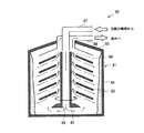
引き続いて本実施形態の遠心分離部60について説明する。遠心分離部60は、遠心分離処理によりスクラバー廃水からばいじんを除去する部分である。ここで、図4は、本実施形態に係る遠心分離部60の概略図である。図4に示すように、遠心分離部60は、収容容器61と、軸管62と、多数の回転板63と、を有している。
Subsequently, the
収容容器61は、軸管62及び回転板63を収容する容器である。収容容器61は、円筒状に形成された円筒部64と、円筒部64の上方に配置された上面部65とを有している。上面部65の中央には上面部65を貫通する流出管66が配置されており、その流出管66の内部には流出管66を貫通する流入管67が配置されている。
The
軸管62は、収容容器61の内部に収容された円管状の部材である。軸管62は、流入管67に連通しており、収容容器61(本体部64)の中心軸に沿って延びている。さらに、軸管62は、電動モータ(図示せず)を駆動源として高速(例えば、10,000rpm)で回転する。図2に示すように、遠心分離部60には沈殿分離部40から排出されたスクラバー廃水が流入するが、具体的にはスクラバー廃水は流入管67を介してこの軸管62へと流入する。さらに、軸管62に流入したスクラバー廃水は、下端に形成された流出孔68を介して収容容器61内に流入する。
The
回転板63は、軸管62とともに回転する部材である。回転板63は、軸管62の軸方向に沿って並べられており、軸管62に運転中は直接固定されている。回転板63は、傘状(円錐状)の形状を有しており、周方向に等間隔で並ぶ流通孔69が形成されている。また、各回転板63の間隔は、図4では広く図示しているが、実際には非常に狭く、その間隔は例えば0.5mmである。なお、この間隔を維持するために、本実施形態では各回転板63の間に例えば厚さ0.5mmのスペーサ(図示せず)が挿入されている。
The rotating
軸管62の内部を通って収容容器61内へ流出したスクラバー廃水は、各回転板63の流通孔69を通り、排出管66から船外へと排出される。そして、スクラバー廃水が回転板63を通過する際、スクラバー廃水には遠心力が加わり、比重の大きいばいじんがスクラバー廃水から分離される。なお、分離されたばいじんは、円筒部64の内壁に堆積する。このように、遠心分離部60に流入したスクラバー廃水は、強制的にばいじん粒子が分離された後、遠心分離部60(収容容器61)から排出される。
The scrubber wastewater that has flowed into the
なお、遠心分離部60を構成する各回転板63は、互いの間隔が非常に狭いため、仮に流入するスクラバー廃水に粒径の大きいばいじんが多く含まれていると、すぐにばいじんが回転板63の間に詰まってしまう。その一方で、遠心分離部60は、遠心力を利用して強制的にばいじんを分離するため、粒径の小さなばいじんを精度良く分離することができる。つまり、遠心分離部60は、粒径の大きなばいじんの除去は苦手であるが、粒径の小さなばいじんの除去には非常に有効である。
In addition, since each
以上のように、本実施形態に係る廃水処理装置32では、粒径の大きなばいじんの除去に有効な沈殿分離部40を上流側に配置している。そして、沈殿分離部40は、小さなエネルギで稼動でき、メンテナンスも容易であり、遠心分離部60よりも小さく構成することができる。また、粒径の小さな粒子のばいじんの除去に有効な遠心分離部60が下流側に配置されている。なお、遠心分離部60の上流に沈殿分離部40が配置されているため、遠心分離部60には粒径の大きなばいじんはほとんど流入しない。このように、本実施形態に係る廃水処理装置32は、互いに補完しあう分離部40、60が最適な配置で組み合わせられており、全体として小さなエネルギで稼動でき、メンテナンスが容易で、設置スペースを小さくでき、しかもスクラバー廃水からばいじんを精度よく除去することができる。
As described above, in the
なお、発明者らの実験により、濁度が5000NTUであったスクラバー廃水が、沈殿分離部40を通過することで濁度が110NTUにまで低下することが確認された。さらに、濁度が110NTUのスクラバー廃水が、遠心分離部60を通過することで濁度が5NTUにまで低下することが確認された。よって、濁度が5000NTU程度のスクラバー廃水であれば、本実施形態に係る廃水処理装置32を一度だけ通過させることで、IMOのガイドラインで定められた排出規定値の25NTU以下に濁度を低減させることができ、その結果、船外への排水することができる。
In addition, it was confirmed by the inventors' experiment that the turbidity is reduced to 110 NTU when the scrubber wastewater having a turbidity of 5000 NTU passes through the
以上、本発明の実施形態について図を参照して説明したが、具体的な構成はこれらの実施形態に限られるものではなく、この発明の要旨を逸脱しない範囲の設計の変更等があっても本発明に含まれる。例えば、以上では、ディーゼルエンジン10の排気の洗浄に用いられたスクラバー廃水を処理する廃水処理装置32について説明したが、廃水処理装置がボイラの排気や焼却炉の排気の洗浄に用いられたスクラバー廃水を処理するものであっても本発明に含まれる。
As described above, the embodiments of the present invention have been described with reference to the drawings. However, the specific configuration is not limited to these embodiments, and even if there is a design change or the like without departing from the gist of the present invention. It is included in the present invention. For example, the scrubber
本発明に係る廃水処理装置は、小さなエネルギで稼動でき、メンテナンスが容易で、設置スペースを小さくでき、しかもスクラバー廃水からばいじんを精度よく除去することができる。よって、廃水処理装置の技術分野において有益である。 The wastewater treatment apparatus according to the present invention can be operated with small energy, can be easily maintained, can reduce the installation space, and can accurately remove dust from the scrubber wastewater. Therefore, it is useful in the technical field of wastewater treatment equipment.
10 ディーゼルエンジン
30 排気再循環ユニット
31 洗浄集じん装置
32 廃水処理装置
40 沈殿分離部
48 傾斜面
60 遠心分離部
100 船舶
101 エンジンシステム
DESCRIPTION OF
Claims (4)
水平方向に対して所定の角度をなす傾斜面を有する多数の傾斜管を備え、前記スクラバー廃水が前記多数の傾斜管を下から上へと抜ける際、各傾斜管の傾斜面にばいじんを沈殿させて前記スクラバー廃水からばいじんを分離する沈殿分離部と、
前記沈殿分離部の下流に配置され、回転軸方向に並んだ多数の回転板を有し、前記多数の回転板を通過する際にスクラバー廃水に遠心力を加え、遠心分離処理により前記スクラバー廃水からばいじんを分離する遠心分離部と、を備えた廃水処理装置。 A wastewater treatment device for removing dust from scrubber wastewater used to clean diesel engine exhaust ,
A plurality of inclined pipes having inclined surfaces that form a predetermined angle with respect to the horizontal direction , and when the scrubber wastewater passes through the multiple inclined pipes from the bottom to the top, dust is deposited on the inclined surfaces of the inclined pipes. precipitation separation unit for separating the dust from the scrubber effluent Te,
It has a large number of rotating plates arranged downstream of the sedimentation separation unit and arranged in the direction of the rotation axis. When passing through the large number of rotating plates, centrifugal force is applied to the scrubber wastewater, and the scrubber wastewater is separated from the scrubber wastewater by centrifugation. A wastewater treatment apparatus comprising: a centrifuge for separating dust.
前記排気を洗浄してスクラバー廃水を排水する洗浄集じん装置と、
前記洗浄集じん装置から排出されたスクラバー廃水からばいじんを除去する請求項1に記載の廃水処理装置と、を備えた排気再循環ユニット。 An exhaust gas recirculation unit that returns exhaust gas from a diesel engine to the diesel engine,
A cleaning dust collector for cleaning the exhaust and draining scrubber waste water;
An exhaust gas recirculation unit comprising: the wastewater treatment device according to claim 1, wherein dust is removed from scrubber wastewater discharged from the cleaning dust collection device.
Priority Applications (7)
| Application Number | Priority Date | Filing Date | Title |
|---|---|---|---|
| JP2012132293A JP5843701B2 (en) | 2012-06-11 | 2012-06-11 | Waste water treatment device, exhaust gas recirculation unit, engine system, and ship |
| CN201380028803.1A CN104334247B (en) | 2012-06-11 | 2013-06-10 | Wastewater treatment equipment, exhaust gas recirculation unit, engine system and ship |
| KR1020157000364A KR101786815B1 (en) | 2012-06-11 | 2013-06-10 | Wastewater treatment device, wastewater treatment system, exhaust gas recirculation unit, engine system, and ship |
| EP13804879.8A EP2862608A4 (en) | 2012-06-11 | 2013-06-10 | Wastewater treatment device, wastewater treatment system, exhaust gas recirculation unit, engine system, and ship |
| KR1020177014354A KR20170061195A (en) | 2012-06-11 | 2013-06-10 | Wastewater treatment device, wastewater treatment system, exhaust gas recirculation unit, engine system, and ship |
| PCT/JP2013/003628 WO2013187038A1 (en) | 2012-06-11 | 2013-06-10 | Wastewater treatment device, wastewater treatment system, exhaust gas recirculation unit, engine system, and ship |
| KR1020177005318A KR20170026637A (en) | 2012-06-11 | 2013-06-10 | Wastewater treatment device, wastewater treatment system, exhaust gas recirculation unit, engine system, and ship |
Applications Claiming Priority (1)
| Application Number | Priority Date | Filing Date | Title |
|---|---|---|---|
| JP2012132293A JP5843701B2 (en) | 2012-06-11 | 2012-06-11 | Waste water treatment device, exhaust gas recirculation unit, engine system, and ship |
Publications (3)
| Publication Number | Publication Date |
|---|---|
| JP2013255876A JP2013255876A (en) | 2013-12-26 |
| JP2013255876A5 JP2013255876A5 (en) | 2015-09-03 |
| JP5843701B2 true JP5843701B2 (en) | 2016-01-13 |
Family
ID=49952784
Family Applications (1)
| Application Number | Title | Priority Date | Filing Date |
|---|---|---|---|
| JP2012132293A Active JP5843701B2 (en) | 2012-06-11 | 2012-06-11 | Waste water treatment device, exhaust gas recirculation unit, engine system, and ship |
Country Status (1)
| Country | Link |
|---|---|
| JP (1) | JP5843701B2 (en) |
Families Citing this family (7)
| Publication number | Priority date | Publication date | Assignee | Title |
|---|---|---|---|---|
| CN106285877A (en) * | 2016-11-07 | 2017-01-04 | 刘晓峰 | A kind of vehicle tail gas dedusting and purifying device |
| JP6378739B2 (en) | 2016-11-18 | 2018-08-22 | 川崎重工業株式会社 | Engine system for large ships |
| JP6810582B2 (en) * | 2016-11-25 | 2021-01-06 | 川崎重工業株式会社 | Wastewater treatment system |
| CN106902973A (en) * | 2017-05-06 | 2017-06-30 | 安徽中粮生化燃料酒精有限公司 | Corn ion device |
| JP6982980B2 (en) | 2017-05-16 | 2021-12-17 | 川崎重工業株式会社 | Wastewater treatment system and ships |
| US11167243B2 (en) | 2017-06-12 | 2021-11-09 | 3Nine Ab | Method and installation for the reduction of sulphur oxides in exhaust gas from marine diesel engines |
| CN109157969B (en) * | 2018-10-29 | 2020-12-11 | 上海中船三井造船柴油机有限公司 | Water treatment system for EGR of marine low-speed diesel engine |
Family Cites Families (10)
| Publication number | Priority date | Publication date | Assignee | Title |
|---|---|---|---|---|
| JPS5128263A (en) * | 1974-09-03 | 1976-03-10 | Kajima Doro Kk | |
| JPS5325973A (en) * | 1976-08-21 | 1978-03-10 | Kobe Steel Ltd | Method and device for separating accompanied carbon continually |
| JPS5756087A (en) * | 1980-09-19 | 1982-04-03 | Ebara Infilco Co Ltd | Activated sludge treatment of waste water |
| JPH07189658A (en) * | 1993-12-28 | 1995-07-28 | Katsuro Yashima | Exhaust gas treating device |
| JPH08155496A (en) * | 1994-12-06 | 1996-06-18 | Shinko Pantec Co Ltd | Method and apparatus for digestion treatment of sludge |
| DE19928600C1 (en) * | 1999-06-22 | 2001-05-03 | Thermoselect Ag Vaduz | Separation device and its use |
| JP2001138235A (en) * | 1999-11-11 | 2001-05-22 | Kurita Water Ind Ltd | Abrasive material recovering apparatus |
| JP2001234374A (en) * | 2000-02-24 | 2001-08-31 | Nisshin Steel Co Ltd | Regenerating method and equipment for cleaning solution for descaling |
| JP3868352B2 (en) * | 2002-08-23 | 2007-01-17 | 三菱重工業株式会社 | Wastewater treatment equipment |
| CN105156179A (en) * | 2010-02-25 | 2015-12-16 | 阿尔法拉瓦尔股份有限公司 | Exhaust gas and gas scrubber fluid cleaning equipment and method |
-
2012
- 2012-06-11 JP JP2012132293A patent/JP5843701B2/en active Active
Also Published As
| Publication number | Publication date |
|---|---|
| JP2013255876A (en) | 2013-12-26 |
Similar Documents
| Publication | Publication Date | Title |
|---|---|---|
| JP5843701B2 (en) | Waste water treatment device, exhaust gas recirculation unit, engine system, and ship | |
| WO2013187038A1 (en) | Wastewater treatment device, wastewater treatment system, exhaust gas recirculation unit, engine system, and ship | |
| RU2529524C2 (en) | Device and method for exhaust gas cleaning and fluid for gas flushing | |
| KR101828734B1 (en) | Exhaust gas treatment equipment for marine diesel engine using low-quality fuel containing high concentration of sulfur component | |
| EP2402288B1 (en) | Cleaning equipment for gas scrubber fluid | |
| RU2668436C1 (en) | Apparatus for removing impurities from fluid stream | |
| JP2015200230A5 (en) | ||
| US20120193221A1 (en) | Radial counterflow muffler for no reduction and pollutant collection | |
| KR101486882B1 (en) | Exhaust gas cleaning system for ship | |
| KR102469956B1 (en) | Wastewater treatment system and ship | |
| JP5798087B2 (en) | Wastewater treatment system, exhaust gas recirculation unit, engine system, and ship | |
| ES2480268T3 (en) | Cleaning equipment for chemical gas washing fluid | |
| JP5843702B2 (en) | Waste water treatment device, exhaust gas recirculation unit, engine system, and ship | |
| US6226984B1 (en) | Marine wet exhaust system | |
| JP6810582B2 (en) | Wastewater treatment system | |
| RU2687461C1 (en) | Method of cleaning oily waters and device for its implementation | |
| CN115193185B (en) | Environment-friendly waste gas treatment equipment | |
| JP4335652B2 (en) | Underwater solid particle concentrator and water treatment system | |
| KR102044853B1 (en) | Non-powered separator using gravity | |
| KR20210078190A (en) | Device for Removing Extraenous Matters in Power Plant's Intake | |
| EP1176293A2 (en) | Marine wet exhaust system |
Legal Events
| Date | Code | Title | Description |
|---|---|---|---|
| A621 | Written request for application examination |
Free format text: JAPANESE INTERMEDIATE CODE: A621 Effective date: 20150415 |
|
| A521 | Request for written amendment filed |
Free format text: JAPANESE INTERMEDIATE CODE: A523 Effective date: 20150717 |
|
| A131 | Notification of reasons for refusal |
Free format text: JAPANESE INTERMEDIATE CODE: A131 Effective date: 20150811 |
|
| A521 | Request for written amendment filed |
Free format text: JAPANESE INTERMEDIATE CODE: A523 Effective date: 20151006 |
|
| A521 | Request for written amendment filed |
Free format text: JAPANESE INTERMEDIATE CODE: A523 Effective date: 20151002 |
|
| TRDD | Decision of grant or rejection written | ||
| A01 | Written decision to grant a patent or to grant a registration (utility model) |
Free format text: JAPANESE INTERMEDIATE CODE: A01 Effective date: 20151117 |
|
| A61 | First payment of annual fees (during grant procedure) |
Free format text: JAPANESE INTERMEDIATE CODE: A61 Effective date: 20151117 |
|
| R150 | Certificate of patent or registration of utility model |
Ref document number: 5843701 Country of ref document: JP Free format text: JAPANESE INTERMEDIATE CODE: R150 |
|
| R250 | Receipt of annual fees |
Free format text: JAPANESE INTERMEDIATE CODE: R250 |