WO2015155973A1 - 操作装置及び車両 - Google Patents
操作装置及び車両 Download PDFInfo
- Publication number
- WO2015155973A1 WO2015155973A1 PCT/JP2015/001914 JP2015001914W WO2015155973A1 WO 2015155973 A1 WO2015155973 A1 WO 2015155973A1 JP 2015001914 W JP2015001914 W JP 2015001914W WO 2015155973 A1 WO2015155973 A1 WO 2015155973A1
- Authority
- WO
- WIPO (PCT)
- Prior art keywords
- palm rest
- palm
- unit
- operator
- input
- Prior art date
- Legal status (The legal status is an assumption and is not a legal conclusion. Google has not performed a legal analysis and makes no representation as to the accuracy of the status listed.)
- Ceased
Links
Images


Classifications
-
- G—PHYSICS
- G06—COMPUTING OR CALCULATING; COUNTING
- G06F—ELECTRIC DIGITAL DATA PROCESSING
- G06F3/00—Input arrangements for transferring data to be processed into a form capable of being handled by the computer; Output arrangements for transferring data from processing unit to output unit, e.g. interface arrangements
- G06F3/01—Input arrangements or combined input and output arrangements for interaction between user and computer
- G06F3/03—Arrangements for converting the position or the displacement of a member into a coded form
- G06F3/033—Pointing devices displaced or positioned by the user, e.g. mice, trackballs, pens or joysticks; Accessories therefor
- G06F3/039—Accessories therefor, e.g. mouse pads
- G06F3/0393—Accessories for touch pads or touch screens, e.g. mechanical guides added to touch screens for drawing straight lines, hard keys overlaying touch screens or touch pads
-
- B—PERFORMING OPERATIONS; TRANSPORTING
- B60—VEHICLES IN GENERAL
- B60K—ARRANGEMENT OR MOUNTING OF PROPULSION UNITS OR OF TRANSMISSIONS IN VEHICLES; ARRANGEMENT OR MOUNTING OF PLURAL DIVERSE PRIME-MOVERS IN VEHICLES; AUXILIARY DRIVES FOR VEHICLES; INSTRUMENTATION OR DASHBOARDS FOR VEHICLES; ARRANGEMENTS IN CONNECTION WITH COOLING, AIR INTAKE, GAS EXHAUST OR FUEL SUPPLY OF PROPULSION UNITS IN VEHICLES
- B60K35/00—Instruments specially adapted for vehicles; Arrangement of instruments in or on vehicles
- B60K35/10—Input arrangements, i.e. from user to vehicle, associated with vehicle functions or specially adapted therefor
-
- B—PERFORMING OPERATIONS; TRANSPORTING
- B60—VEHICLES IN GENERAL
- B60R—VEHICLES, VEHICLE FITTINGS, OR VEHICLE PARTS, NOT OTHERWISE PROVIDED FOR
- B60R11/00—Arrangements for holding or mounting articles, not otherwise provided for
- B60R11/02—Arrangements for holding or mounting articles, not otherwise provided for for radio sets, television sets, telephones, or the like; Arrangement of controls thereof
- B60R11/0264—Arrangements for holding or mounting articles, not otherwise provided for for radio sets, television sets, telephones, or the like; Arrangement of controls thereof for control means
-
- B—PERFORMING OPERATIONS; TRANSPORTING
- B60—VEHICLES IN GENERAL
- B60R—VEHICLES, VEHICLE FITTINGS, OR VEHICLE PARTS, NOT OTHERWISE PROVIDED FOR
- B60R16/00—Electric or fluid circuits specially adapted for vehicles and not otherwise provided for; Arrangement of elements of electric or fluid circuits specially adapted for vehicles and not otherwise provided for
- B60R16/02—Electric or fluid circuits specially adapted for vehicles and not otherwise provided for; Arrangement of elements of electric or fluid circuits specially adapted for vehicles and not otherwise provided for electric constitutive elements
- B60R16/023—Electric or fluid circuits specially adapted for vehicles and not otherwise provided for; Arrangement of elements of electric or fluid circuits specially adapted for vehicles and not otherwise provided for electric constitutive elements for transmission of signals between vehicle parts or subsystems
-
- G—PHYSICS
- G06—COMPUTING OR CALCULATING; COUNTING
- G06F—ELECTRIC DIGITAL DATA PROCESSING
- G06F3/00—Input arrangements for transferring data to be processed into a form capable of being handled by the computer; Output arrangements for transferring data from processing unit to output unit, e.g. interface arrangements
- G06F3/01—Input arrangements or combined input and output arrangements for interaction between user and computer
- G06F3/016—Input arrangements with force or tactile feedback as computer generated output to the user
-
- G—PHYSICS
- G06—COMPUTING OR CALCULATING; COUNTING
- G06F—ELECTRIC DIGITAL DATA PROCESSING
- G06F3/00—Input arrangements for transferring data to be processed into a form capable of being handled by the computer; Output arrangements for transferring data from processing unit to output unit, e.g. interface arrangements
- G06F3/01—Input arrangements or combined input and output arrangements for interaction between user and computer
- G06F3/03—Arrangements for converting the position or the displacement of a member into a coded form
- G06F3/033—Pointing devices displaced or positioned by the user, e.g. mice, trackballs, pens or joysticks; Accessories therefor
- G06F3/0354—Pointing devices displaced or positioned by the user, e.g. mice, trackballs, pens or joysticks; Accessories therefor with detection of 2D relative movements between the device, or an operating part thereof, and a plane or surface, e.g. 2D mice, trackballs, pens or pucks
- G06F3/03547—Touch pads, in which fingers can move on a surface
-
- G—PHYSICS
- G06—COMPUTING OR CALCULATING; COUNTING
- G06F—ELECTRIC DIGITAL DATA PROCESSING
- G06F3/00—Input arrangements for transferring data to be processed into a form capable of being handled by the computer; Output arrangements for transferring data from processing unit to output unit, e.g. interface arrangements
- G06F3/01—Input arrangements or combined input and output arrangements for interaction between user and computer
- G06F3/03—Arrangements for converting the position or the displacement of a member into a coded form
- G06F3/033—Pointing devices displaced or positioned by the user, e.g. mice, trackballs, pens or joysticks; Accessories therefor
- G06F3/0354—Pointing devices displaced or positioned by the user, e.g. mice, trackballs, pens or joysticks; Accessories therefor with detection of 2D relative movements between the device, or an operating part thereof, and a plane or surface, e.g. 2D mice, trackballs, pens or pucks
- G06F3/03548—Sliders, in which the moving part moves in a plane
-
- G—PHYSICS
- G06—COMPUTING OR CALCULATING; COUNTING
- G06F—ELECTRIC DIGITAL DATA PROCESSING
- G06F3/00—Input arrangements for transferring data to be processed into a form capable of being handled by the computer; Output arrangements for transferring data from processing unit to output unit, e.g. interface arrangements
- G06F3/01—Input arrangements or combined input and output arrangements for interaction between user and computer
- G06F3/03—Arrangements for converting the position or the displacement of a member into a coded form
- G06F3/033—Pointing devices displaced or positioned by the user, e.g. mice, trackballs, pens or joysticks; Accessories therefor
- G06F3/038—Control and interface arrangements therefor, e.g. drivers or device-embedded control circuitry
-
- G—PHYSICS
- G06—COMPUTING OR CALCULATING; COUNTING
- G06F—ELECTRIC DIGITAL DATA PROCESSING
- G06F3/00—Input arrangements for transferring data to be processed into a form capable of being handled by the computer; Output arrangements for transferring data from processing unit to output unit, e.g. interface arrangements
- G06F3/01—Input arrangements or combined input and output arrangements for interaction between user and computer
- G06F3/048—Interaction techniques based on graphical user interfaces [GUI]
- G06F3/0487—Interaction techniques based on graphical user interfaces [GUI] using specific features provided by the input device, e.g. functions controlled by the rotation of a mouse with dual sensing arrangements, or of the nature of the input device, e.g. tap gestures based on pressure sensed by a digitiser
- G06F3/0488—Interaction techniques based on graphical user interfaces [GUI] using specific features provided by the input device, e.g. functions controlled by the rotation of a mouse with dual sensing arrangements, or of the nature of the input device, e.g. tap gestures based on pressure sensed by a digitiser using a touch-screen or digitiser, e.g. input of commands through traced gestures
-
- B—PERFORMING OPERATIONS; TRANSPORTING
- B60—VEHICLES IN GENERAL
- B60K—ARRANGEMENT OR MOUNTING OF PROPULSION UNITS OR OF TRANSMISSIONS IN VEHICLES; ARRANGEMENT OR MOUNTING OF PLURAL DIVERSE PRIME-MOVERS IN VEHICLES; AUXILIARY DRIVES FOR VEHICLES; INSTRUMENTATION OR DASHBOARDS FOR VEHICLES; ARRANGEMENTS IN CONNECTION WITH COOLING, AIR INTAKE, GAS EXHAUST OR FUEL SUPPLY OF PROPULSION UNITS IN VEHICLES
- B60K2360/00—Indexing scheme associated with groups B60K35/00 or B60K37/00 relating to details of instruments or dashboards
- B60K2360/143—Touch sensitive instrument input devices
-
- B—PERFORMING OPERATIONS; TRANSPORTING
- B60—VEHICLES IN GENERAL
- B60K—ARRANGEMENT OR MOUNTING OF PROPULSION UNITS OR OF TRANSMISSIONS IN VEHICLES; ARRANGEMENT OR MOUNTING OF PLURAL DIVERSE PRIME-MOVERS IN VEHICLES; AUXILIARY DRIVES FOR VEHICLES; INSTRUMENTATION OR DASHBOARDS FOR VEHICLES; ARRANGEMENTS IN CONNECTION WITH COOLING, AIR INTAKE, GAS EXHAUST OR FUEL SUPPLY OF PROPULSION UNITS IN VEHICLES
- B60K35/00—Instruments specially adapted for vehicles; Arrangement of instruments in or on vehicles
- B60K35/20—Output arrangements, i.e. from vehicle to user, associated with vehicle functions or specially adapted therefor
- B60K35/28—Output arrangements, i.e. from vehicle to user, associated with vehicle functions or specially adapted therefor characterised by the type of the output information, e.g. video entertainment or vehicle dynamics information; characterised by the purpose of the output information, e.g. for attracting the attention of the driver
-
- B—PERFORMING OPERATIONS; TRANSPORTING
- B60—VEHICLES IN GENERAL
- B60K—ARRANGEMENT OR MOUNTING OF PROPULSION UNITS OR OF TRANSMISSIONS IN VEHICLES; ARRANGEMENT OR MOUNTING OF PLURAL DIVERSE PRIME-MOVERS IN VEHICLES; AUXILIARY DRIVES FOR VEHICLES; INSTRUMENTATION OR DASHBOARDS FOR VEHICLES; ARRANGEMENTS IN CONNECTION WITH COOLING, AIR INTAKE, GAS EXHAUST OR FUEL SUPPLY OF PROPULSION UNITS IN VEHICLES
- B60K35/00—Instruments specially adapted for vehicles; Arrangement of instruments in or on vehicles
- B60K35/60—Instruments characterised by their location or relative disposition in or on vehicles
-
- B—PERFORMING OPERATIONS; TRANSPORTING
- B60—VEHICLES IN GENERAL
- B60K—ARRANGEMENT OR MOUNTING OF PROPULSION UNITS OR OF TRANSMISSIONS IN VEHICLES; ARRANGEMENT OR MOUNTING OF PLURAL DIVERSE PRIME-MOVERS IN VEHICLES; AUXILIARY DRIVES FOR VEHICLES; INSTRUMENTATION OR DASHBOARDS FOR VEHICLES; ARRANGEMENTS IN CONNECTION WITH COOLING, AIR INTAKE, GAS EXHAUST OR FUEL SUPPLY OF PROPULSION UNITS IN VEHICLES
- B60K35/00—Instruments specially adapted for vehicles; Arrangement of instruments in or on vehicles
- B60K35/80—Arrangements for controlling instruments
- B60K35/81—Arrangements for controlling instruments for controlling displays
-
- B—PERFORMING OPERATIONS; TRANSPORTING
- B60—VEHICLES IN GENERAL
- B60K—ARRANGEMENT OR MOUNTING OF PROPULSION UNITS OR OF TRANSMISSIONS IN VEHICLES; ARRANGEMENT OR MOUNTING OF PLURAL DIVERSE PRIME-MOVERS IN VEHICLES; AUXILIARY DRIVES FOR VEHICLES; INSTRUMENTATION OR DASHBOARDS FOR VEHICLES; ARRANGEMENTS IN CONNECTION WITH COOLING, AIR INTAKE, GAS EXHAUST OR FUEL SUPPLY OF PROPULSION UNITS IN VEHICLES
- B60K37/00—Dashboards
- B60K37/20—Dashboard panels
-
- G—PHYSICS
- G06—COMPUTING OR CALCULATING; COUNTING
- G06F—ELECTRIC DIGITAL DATA PROCESSING
- G06F3/00—Input arrangements for transferring data to be processed into a form capable of being handled by the computer; Output arrangements for transferring data from processing unit to output unit, e.g. interface arrangements
- G06F3/01—Input arrangements or combined input and output arrangements for interaction between user and computer
- G06F3/048—Interaction techniques based on graphical user interfaces [GUI]
- G06F3/0481—Interaction techniques based on graphical user interfaces [GUI] based on specific properties of the displayed interaction object or a metaphor-based environment, e.g. interaction with desktop elements like windows or icons, or assisted by a cursor's changing behaviour or appearance
- G06F3/04817—Interaction techniques based on graphical user interfaces [GUI] based on specific properties of the displayed interaction object or a metaphor-based environment, e.g. interaction with desktop elements like windows or icons, or assisted by a cursor's changing behaviour or appearance using icons
-
- G—PHYSICS
- G06—COMPUTING OR CALCULATING; COUNTING
- G06F—ELECTRIC DIGITAL DATA PROCESSING
- G06F3/00—Input arrangements for transferring data to be processed into a form capable of being handled by the computer; Output arrangements for transferring data from processing unit to output unit, e.g. interface arrangements
- G06F3/01—Input arrangements or combined input and output arrangements for interaction between user and computer
- G06F3/048—Interaction techniques based on graphical user interfaces [GUI]
- G06F3/0484—Interaction techniques based on graphical user interfaces [GUI] for the control of specific functions or operations, e.g. selecting or manipulating an object, an image or a displayed text element, setting a parameter value or selecting a range
- G06F3/04847—Interaction techniques to control parameter settings, e.g. interaction with sliders or dials
-
- G—PHYSICS
- G06—COMPUTING OR CALCULATING; COUNTING
- G06F—ELECTRIC DIGITAL DATA PROCESSING
- G06F3/00—Input arrangements for transferring data to be processed into a form capable of being handled by the computer; Output arrangements for transferring data from processing unit to output unit, e.g. interface arrangements
- G06F3/01—Input arrangements or combined input and output arrangements for interaction between user and computer
- G06F3/048—Interaction techniques based on graphical user interfaces [GUI]
- G06F3/0487—Interaction techniques based on graphical user interfaces [GUI] using specific features provided by the input device, e.g. functions controlled by the rotation of a mouse with dual sensing arrangements, or of the nature of the input device, e.g. tap gestures based on pressure sensed by a digitiser
- G06F3/0488—Interaction techniques based on graphical user interfaces [GUI] using specific features provided by the input device, e.g. functions controlled by the rotation of a mouse with dual sensing arrangements, or of the nature of the input device, e.g. tap gestures based on pressure sensed by a digitiser using a touch-screen or digitiser, e.g. input of commands through traced gestures
- G06F3/04883—Interaction techniques based on graphical user interfaces [GUI] using specific features provided by the input device, e.g. functions controlled by the rotation of a mouse with dual sensing arrangements, or of the nature of the input device, e.g. tap gestures based on pressure sensed by a digitiser using a touch-screen or digitiser, e.g. input of commands through traced gestures for inputting data by handwriting, e.g. gesture or text
Definitions
- the present disclosure relates to an operation device including an operation surface that receives an operation input by an operator's fingertip and a palm rest on which the operator's palm is placed, and a vehicle including the operation device.
- the inventors of the present invention have found the following regarding the operation device.
- the palm resting surface on the palm rest is provided above the operation surface of the touch pad.
- the operability is improved. That is, the operability is improved when the tangent plane of the palm placement surface is arranged on the surface side of the operation surface of the touch pad.
- the configuration surface of the touchpad described in Patent Document 1 is adopted when the palm mounting surface is above the operation surface of the touchpad, the operation surface closer to the palmrest is closer to the palmrest. Inclining away from the surface makes it easier for the claws to hit the operation surface.
- the present disclosure provides an operation device that includes an operation surface that receives an operation input by an operator's fingertips and a palm rest on which the operator's palm is placed, and a vehicle that includes the operation device. It was made for the purpose of ensuring the property over a wide area.
- the operation device includes a palm rest on which an operator's palm is placed and an operation unit having an operation surface that receives an operation input by a fingertip.
- the palm rest is provided closer to the operator than the operation surface, and the tangent plane of the palm mounting surface is on the surface side of the operation surface (for example, when the operation surface faces upward) (Above the operation surface). For this reason, the operability of the operation surface is good.
- the operation surface is inclined so that the portion near the palm rest is closer to the palm placement surface of the palm rest as it is closer to the palm rest than the portion away from the palm rest.
- the operation unit may accept an operation input by moving the operation unit.
- the operation unit accepts an operation input from the fingertip on the operation surface, and also accepts an operation input by moving itself. For this reason, two types of operation inputs can be received by one operation unit, the operation time can be shortened by properly using each operation without changing the finger according to the operation screen, and the number of parts required for the entire operation device Can be reduced.
- movement of the operation unit may be prohibited by motor drive control. In this case, since the operation surface does not move during operation of the operation surface, the operability of the operation surface can be further ensured.
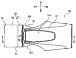
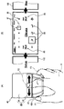
- FIG. 2 is a plan view illustrating the configuration of the operation device in the vehicle.
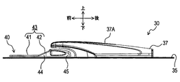
- FIG. 3 is a left side view illustrating the configuration of the operation device.
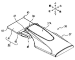
- FIG. 4 is a perspective view illustrating the configuration of the operation device.
- FIG. 5 is a plan view and a left side view illustrating the configuration of the operation unit of the operation device.
- 6 is a cross-sectional view taken along line VI-VI in FIG.
- FIG. 7 is an enlarged cross-sectional view illustrating a configuration related to the operation unit in FIG. FIG.
- FIG. 8 is a block diagram showing a part of the control system in the vehicle.
- FIG. 9 is a flowchart showing processing executed in the control system.
- 10A and 10B are explanatory diagrams illustrating an operation example of processing executed in the control system.
- FIGS. 11A and 11B are explanatory diagrams illustrating another operation example of processing executed in the control system.
- 12A and 12B are explanatory diagrams illustrating still another operation example of the process executed in the control system.
- FIGS. 13A and 13B are explanatory diagrams showing still another operation example of processing executed in the control system.
- FIGS. 14A and 14B are explanatory diagrams illustrating the effect of the operation device in comparison with the comparative example.
- 15A and 15B are explanatory diagrams illustrating other effects of the operation device.
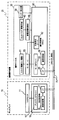
- the vehicle 1 includes a display 10 and a remote control device 20 provided inside a passenger compartment 3.
- the display 10 is provided on the upper surface or front surface of the dashboard 9 (the front surface when viewed from the driver D), and displays various information on the driver D.
- the remote operation device 20 includes an operation device 30 (an example of an operation device) and an operation control unit 60.
- the operation device 30 is attached to a to-be-attached surface 35 provided on the upper surface of the console 34, and is configured as follows.
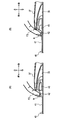
- the operation device 30 includes a palm rest 37 on which a palm H (see FIG. 10) of an operator (driver D or a passenger in a passenger seat not shown) is placed, an operation unit 40, It has.
- the operation unit 40 is provided so as to be movable on the attachment surface 35 in any direction, front, back, left, and right.
- the palm rest 37 protrudes upward from the rear side (front side as viewed from the operator) of the operation surface 40 on the attachment surface 35, and then extends forward to reach the upper rear portion of the operation unit 40.
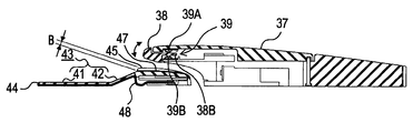
- an enter switch 38 that can be operated in both the upper and lower directions is provided at the front end of the palm rest 37.
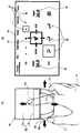
- the operation unit 40 includes a touch pad unit 44 whose surface is an operation surface 43 including a first portion 41 and a second portion 42, and is picked up by an operator when the operation unit 40 is moved as described above. And an operation knob 45 to be operated.
- the first portion 41 is formed in a rectangle having sides in the front-rear and left-right directions, and forms a plane parallel to the attachment surface 35.
- the second portion 42 is connected to the rear end of the first portion 41 and is configured to have a rectangular shape whose length in the front-rear direction is smaller than that of the first portion 41.
- the 2nd part 42 comprises the plane which inclined so that it might approach the mounting surface 37A of the palm H in the said palm rest 37, so that the palm rest 37 was approached.
- the operation knob portion 45 is connected to the rear end of the second portion 42 in the touch pad portion 44, and has a thickness (length in the vertical direction) that allows the pair of left and right side surfaces 45A to be easily picked by a finger. is doing.
- a concave portion 47 is formed on the upper surface of the operation knob portion 45 at a portion facing the enter switch 38.
- the pair of left and right side surfaces 45A of the operation knob portion 45 are curved so that the distance in the left-right direction (that is, the width in the left-right direction of the operation knob portion 45) gradually decreases toward the rear. is doing.
- the concave portion 47 is formed on the upper surface of the operation knob portion 45 so as to penetrate in the front-rear direction.
- the recess 47 has a width (a length in the left-right direction) that is at least a front end portion (a portion facing the enter switch 38 when the operation unit 40 is at the reference position) larger than the enter switch 38. A). For this reason, even if the operation part 40 is moved on the to-be-attached surface 35, the recessed part 47 always exists under the enter switch 38.
- the enter switch 38 extends inside the palm rest 37, and the tip 38B is supported inside the palm rest 37 via a hinge (not shown). For this reason, the enter switch 38 can be rotated in the vertical direction as indicated by an arrow in FIG.
- an enter detection unit 39 including two tactile switches 39A and 39B is provided inside the palm rest 37.
- the tactile switch 39A is pressed by a portion of the enter switch 38 accommodated inside the palm rest 37 when a portion exposed to the outside of the palm rest 37 in the enter switch 38 is pulled upward.
- the tactile switch 39 ⁇ / b> B is pressed by a portion housed inside the palm rest 37 in the enter switch 38 when a portion exposed to the outside of the palm rest 37 in the enter switch 38 is pushed downward.
- the depth B of the recess 47 is such a depth that the nail N (see FIG. 14) of the second finger F2 does not touch the recess 47 when such an operation of the enter switch 38 is performed, and the operation can be performed satisfactorily. Designed to.
- an electrostatic electrode path 48 is provided on the lower surface of the touch pad portion 44 over the entire lower surface of both the first portion 41 and the second portion 42.
- the electrostatic electrode path 48 is connected to the electrostatic capacity control unit 49 and detects the electrostatic capacity of each part, thereby detecting which part is touched by the fingertip of the operator.
- the capacitance control unit 49 detects an area having a certain width at the boundary between the first portion 41 and the second portion 42 as a dead zone that does not detect that the fingertip is touched.
- FIG. 8 shows a part extracted from the control system of the vehicle 1 related to the remote control device 20 and the display 10.
- the electrical connection relationships of the respective parts are indicated by solid arrows, but some mechanical connection relationships are also indicated by dashed arrows.
- the slide mechanism 51 that supports the operation unit 40 so as to be slidable along the attachment surface 35 includes a left-right direction (hereinafter also referred to as X-axis direction) and a front-rear direction (hereinafter referred to as Y-axis direction).
- a pair of motors 53 for applying a reaction force to each of them are provided. For this reason, the reaction force can be applied to the operation unit 40 in any direction of 360 ° along the XY plane.
- various well-known mechanisms can be applied. For example, a mechanism disclosed in JP-A-2005-250983 can be applied.
- the detection result of the enter detection unit 39 and the detection result of the capacitance control unit 49 are input to the operation control unit 60 together with the drive amount of the pair of motors 53, and the operation control unit 60 sets the pair of motors 53. Is driven.
- the operation control unit 60 includes a motor driver 61 that drives the pair of motors 53, and a position detection unit 62 that detects the position coordinates of the operation unit 40 in the XY directions based on the drive amount.
- the operation control unit 60 is configured as a microcomputer (ECU) including a CPU, ROM, and RAM, and further includes a communication control unit 66 that communicates with the CAN bus 70 via an interface (I / F) 65. ing.
- the display 10 includes an LCD monitor 11 that displays an image and a display control unit 15 that controls a display state on the LCD monitor 11.
- the display control unit 15 is also configured as a microcomputer including a CPU, a ROM, and a RAM, and performs communication between the display driver 16 that drives the LCD monitor 11 and the CAN bus 70 via an interface (I / F) 17. And a control unit 18.
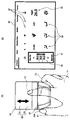
- FIG. 10B shows an example of a screen displayed on the LCD monitor 11.
- This screen is an air conditioning setting screen 80 for performing settings related to air conditioning in the passenger compartment 3.
- the cursor 81 is moved up and down in the same manner as the operation unit 40 by other processes not shown. It is moved left and right.
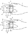
- FIG. 10A shows an example in which the operator places the palm H of the right hand on the palm rest 37 and operates the operation unit 40 by gripping the operation unit 40 with the first finger F1 and the third finger F3.
- FIGS. 11A to 15 below also illustrate the case where the operator operates the operation device 30 with the right hand. When the operator operates the operation device 30 with the left hand, substantially the same description can be made, and even in the drawing, the arrangement of the first finger F1 and the third finger F3 is simply changed and there is no significant change.
- the air conditioning setting screen 80 is for setting a pair of temperature setting icons 85 for individually setting the setting temperatures of the driver seat and the passenger seat, a plurality of wind direction setting icons 86 for setting the wind direction, and setting the wind force.
- a plurality of wind power setting icons 87 are provided.
- a reaction force is applied to the operation unit 40 so that the cursor 81 is drawn to the center of the icons 85 to 87.
- a known process such as is executed.
- S9 it is detected at which position on the operation surface 43 the finger is placed, and in S11, it is determined whether or not the finger is placed on the first portion 41. If the finger is placed on the first portion 41 (S11: Y), the process proceeds to S12, and after a two-dimensional input or swipe input is accepted, the process proceeds to S1. On the other hand, if it is determined in S11 that the finger is not placed on the first part 41, that is, placed on the second part (S11N), the process proceeds to S13, and a flick input is accepted. Then, the process proceeds to S1.
- the two-dimensional input in S12 is an input operation in which the operator uses the first portion 41 of the operation surface 43 as a two-dimensional input means such as a handwriting input means.
- the swipe input is an input operation in which the operator strokes the first portion 41 of the operation surface 43 so as to sweep it.
- the flick input in S13 is an input operation in which the operator strokes the second portion 42 of the operation surface 43 so as to play.
- FIG. 11 is a diagram for explaining swipe input.
- FIG. 11B when the cursor 81 is placed on the temperature setting icon 85 on the above-described air conditioning setting screen 80, numerical values (set temperatures) are arranged in the cursor 81 in the vertical direction. Is displayed.
- the first portion 41 is swiped up and down by the second finger F2 (may be another finger; the same applies hereinafter) as shown by an arrow in FIG. 11A (S11: Y )
- the numerical value displayed in the cursor 81 is scrolled up and down (S12).
- the operator can adjust the set temperature of the air conditioning displayed on the temperature setting icon 85 to a desired numerical value.
- FIG. 12 is a diagram for explaining two-dimensional input.
- FIG. 12B shows another example of a screen displayed on the LCD monitor 11.
- This screen is a destination input screen 90 for performing destination input in a car navigation device (not shown).
- the destination input screen 90 includes a cursor 91 that moves in the same manner when the operation unit 40 is moved in the front-rear and left-right directions, a character candidate icon 92 that displays character candidates, and handwriting input that inputs characters by handwriting An area 93 is provided.
- the second finger F2 when a character is handwritten to the first portion 41 by the second finger F2 (S11: Y), the second finger F2 is input to the handwriting input area 93.
- a line is drawn according to the locus of the part touched in (S12). By this operation, the operator can draw a desired character in the handwriting input area 93.
- FIG. 13 is a diagram for explaining flick input.
- the above-described air conditioning setting screen 80 is displayed on the LCD monitor 11, a map screen 100 displaying a map on the left and right, and a setup screen 110 for the operator to set up.
- the software is set so that and are adjacent to each other.
- the second finger F2 is stroked so that the second portion 42 is flipped in the left-right direction (S11: N)
- the entire screen is moved in the stroked direction. It is moved (S13).
- the screen displayed on the LCD monitor 11 can be switched from the air conditioning setting screen 80 to the map screen 100 or the setup screen 110.
- the operation surface 43 that receives an operation input by a fingertip is provided on the surface of the operation unit 40 that receives an operation input by moving in the XY direction. That is, the operation unit 40 has two types of operation devices (an operation knob unit 45 as a main operation device and a touch pad unit 44 as a sub operation device) integrated so that the finger can be changed without changing the operation screen.
- the operation time can be shortened by properly using each operation, and the number of parts of the entire operation device in the vehicle 1 can be reduced to simplify the device configuration.
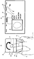
- the palm rest 37 protrudes from the rear (front side as viewed from the operator) to the upper part of the operation unit 40 with respect to the movement range of the operation unit 40 on the mounted surface 35. That is, all the tangential planes of the placement surface 37 ⁇ / b> A on which the palm H is placed on the palm rest 37 are arranged on the surface side of the operation surface 43. For this reason, the operator (driver D or a passenger in the passenger seat) can satisfactorily operate the operation unit 40 with the palm H placed on the palm rest 37 while sitting.
- the second portion 42 forms a plane that is inclined so as to be closer to the placement surface 37 ⁇ / b> A of the palm H in the palm rest 37 as it approaches the palm rest 37. For this reason, as shown to FIG. 14 (A), the angle
- the first portion 41 and the second portion 42 are a series of planes parallel to the mounted surface 35, and the rear end of the second portion 42 If the operation knob portion 45 is provided so as to stand up, the operability may be lowered. In this case, when the second portion 42 is operated, the nail N of the second finger F2 that operates the portion hits the second portion 42, and the operability of the second portion 42 may be reduced. .
- the angle formed between the tangent plane on the belly of the second finger F2 that operates the second portion 42 and the second portion 42 is small, and thus the second portion It is suppressed that the nail
- the inclination angle of the second portion 42 with respect to the attachment surface 35 has an optimum value depending on the apparatus configuration, but is preferably about 45 ° (30 ° to 60 °), for example.
- the pair of left and right side surfaces 45A of the operation knob 45 is curved so that the distance in the left-right direction (the width in the direction to be picked) gradually decreases toward the rear. Therefore, an operator having a small palm H and a small interval W1 between the fingertip of the first finger F1 and the fingertip of the third finger F3 when the operation knob portion 45 is picked is shown in FIG. What is necessary is just to pick the back of the part 45.
- FIG. an operator who has a large palm H and has a large interval W2 between the fingertip of the first finger F1 and the fingertip of the third finger F3 when gripping the operation knob portion 45 is shown in FIG. What is necessary is just to pick the front of the part 45.
- FIG. Therefore, the operation unit 40 in the present embodiment can be operated satisfactorily regardless of the size of the hand.
- the mounted surface 35 is the support surface
- the palm rest 37 is the palm rest
- the first portion 41 is the first portion
- the second portion 42 is the second portion
- the operation surface 43 corresponds to the operation surface
- the operation unit 40 corresponds to the operation unit
- the pair of motors 53 corresponds to the movement prohibition unit
- the pair of left and right side surfaces 45A of the operation knob unit 45 corresponds to the knob
- the enter switch 38 corresponds to the switch.
- the embodiment is not limited to the above-described embodiment, and includes various embodiments.
- the knob portion of the operation knob portion 45 may be configured in a simple rectangle, or the side surface of the touch pad portion 44 may be directly picked without the knob portion.
- the touch pad unit 44 is fixed to the attachment surface 35 and may not have a function as an operation unit that can move in the XY directions.
- the operation surface 43 may not be divided into the first part 41 and the second part 42, and the whole may be configured as a series of curved surfaces. Also in that case, if the portion near the palm rest 37 of the operation surface 43 is inclined so as to be closer to the placement surface 37 ⁇ / b> A as the palm rest 37 is closer than the portion away from the palm rest 37, FIG. 14 is used. The above-described effects described above occur. In this case, the operation surface 43 may be divided into the 1st part 41 and the 2nd part 42 from which the operation object received is different, and does not need to be divided.
- the operation targets received for the respective portions are different. Can be used properly. For this reason, the operator can determine whether the second finger F2 is in contact with the first portion 41 or the second portion 42 without looking at the operation surface 43, and so-called blind operation is possible. It becomes.
- the 1st part 41 and the 2nd part 42 may be comprised by the independent separate touchscreen.
- an area having a certain width at the boundary between the first part 41 and the second part 42 is a dead band that does not detect whether the fingertip is touched.
- a dead band is provided. It does not have to be.
- the operation with respect to the first portion 41 and the operation with respect to the second portion 42 can be more clearly distinguished when such a dead zone is provided.
- the enter switch 38 does not necessarily need to be provided, and even if the enter switch 38 is provided, the corresponding recess 47 may not necessarily be provided.
- the operation device 30 of the above-described embodiment includes the enter switch 38 that is operated in the direction of approaching or separating from the operation unit 40 at the end of the palm rest 37 on the operation surface 43 side. A recess 47 is formed in the operation unit 40 at a position facing the enter switch 38. For this reason, the situation that the nail
- the operability of the enter switch 38 may be ensured without providing the recess 47.
- the distance from the mounting surface 37A is increased, and the operability of the operation knob 45 may be lowered.
- the concave portion 47 is provided as in the above-described embodiment, the interval between the operation knob portion 45 and the mounting surface 37A is reduced to ensure the operability of the operation knob portion 45, while Thus, the operability of the enter switch 38 can be ensured.
- the use of the operating device is not limited to the above-described embodiment.
- the operating device may be provided on a dashboard, a steering wheel, or a door trim.
- the operating device can be used for various purposes other than the vehicle, and may be provided in, for example, a personal computer or a peripheral device thereof.
- the configurations of the above-described embodiment and each modification can be arbitrarily combined.
Landscapes
- Engineering & Computer Science (AREA)
- General Engineering & Computer Science (AREA)
- Theoretical Computer Science (AREA)
- Human Computer Interaction (AREA)
- Physics & Mathematics (AREA)
- General Physics & Mathematics (AREA)
- Mechanical Engineering (AREA)
- Chemical & Material Sciences (AREA)
- Combustion & Propulsion (AREA)
- Transportation (AREA)
- User Interface Of Digital Computer (AREA)
- Position Input By Displaying (AREA)
Priority Applications (1)
| Application Number | Priority Date | Filing Date | Title |
|---|---|---|---|
| US15/300,804 US9965061B2 (en) | 2014-04-10 | 2015-04-06 | Input device and vehicle |
Applications Claiming Priority (2)
| Application Number | Priority Date | Filing Date | Title |
|---|---|---|---|
| JP2014081297A JP6273989B2 (ja) | 2014-04-10 | 2014-04-10 | 操作装置及び車両 |
| JP2014-081297 | 2014-04-10 |
Publications (1)
| Publication Number | Publication Date |
|---|---|
| WO2015155973A1 true WO2015155973A1 (ja) | 2015-10-15 |
Family
ID=54287559
Family Applications (1)
| Application Number | Title | Priority Date | Filing Date |
|---|---|---|---|
| PCT/JP2015/001914 Ceased WO2015155973A1 (ja) | 2014-04-10 | 2015-04-06 | 操作装置及び車両 |
Country Status (3)
| Country | Link |
|---|---|
| US (1) | US9965061B2 (enExample) |
| JP (1) | JP6273989B2 (enExample) |
| WO (1) | WO2015155973A1 (enExample) |
Cited By (3)
| Publication number | Priority date | Publication date | Assignee | Title |
|---|---|---|---|---|
| JP2018099976A (ja) * | 2016-12-20 | 2018-06-28 | トヨタ自動車九州株式会社 | 車両用操作部構造 |
| EP3421300A4 (en) * | 2016-02-23 | 2019-12-18 | KYOCERA Corporation | CONTROL UNIT FOR A VEHICLE |
| US20240004416A1 (en) * | 2020-12-02 | 2024-01-04 | Bayerische Motoren Werke Aktiengesellschaft | Operating Element for a Motor Vehicle |
Families Citing this family (7)
| Publication number | Priority date | Publication date | Assignee | Title |
|---|---|---|---|---|
| USD829765S1 (en) * | 2015-09-28 | 2018-10-02 | Everi Games Inc. | Display screen or portion thereof with animated graphical user interface |
| TWI678656B (zh) * | 2018-05-09 | 2019-12-01 | 和碩聯合科技股份有限公司 | 電腦系統及其介面操作方法 |
| USD944868S1 (en) | 2018-09-07 | 2022-03-01 | Crown Equipment Corporation | Arm pad |
| USD944869S1 (en) | 2018-09-07 | 2022-03-01 | Crown Equipment Corporation | Arm pad |
| USD922279S1 (en) | 2018-10-17 | 2021-06-15 | Crown Equipment Corporation | Control pod |
| DE102020000729A1 (de) * | 2020-02-04 | 2021-08-05 | Man Truck & Bus Se | Anordnung einer Handballenauflage und eines Bedienelements für ein Fahrzeug |
| US11796660B2 (en) * | 2020-07-24 | 2023-10-24 | Fujifilm Sonosite, Inc. | Systems and methods for customized user interface |
Citations (1)
| Publication number | Priority date | Publication date | Assignee | Title |
|---|---|---|---|---|
| US6025831A (en) * | 1997-11-19 | 2000-02-15 | Avrotec, Inc. | Method and apparatus for accurate controls input |
Family Cites Families (7)
| Publication number | Priority date | Publication date | Assignee | Title |
|---|---|---|---|---|
| JP4220416B2 (ja) | 2004-03-05 | 2009-02-04 | アルプス電気株式会社 | 力覚付与型入力装置 |
| US8319832B2 (en) * | 2008-01-31 | 2012-11-27 | Denso Corporation | Input apparatus and imaging apparatus |
| JP4891286B2 (ja) | 2008-04-11 | 2012-03-07 | 株式会社デンソー | 遠隔操作装置 |
| JP2013235359A (ja) | 2012-05-08 | 2013-11-21 | Tokai Rika Co Ltd | 情報処理装置及び入力装置 |
| JP2014133474A (ja) | 2013-01-10 | 2014-07-24 | Denso Corp | 車載用入力装置 |
| JP6020319B2 (ja) | 2013-04-10 | 2016-11-02 | 株式会社デンソー | 操作装置 |
| FR3019661B1 (fr) * | 2014-04-04 | 2017-07-14 | Thales Sa | Amelioration de l'ergonomie d'un dispositif d'entree de donnees |
-
2014
- 2014-04-10 JP JP2014081297A patent/JP6273989B2/ja not_active Expired - Fee Related
-
2015
- 2015-04-06 WO PCT/JP2015/001914 patent/WO2015155973A1/ja not_active Ceased
- 2015-04-06 US US15/300,804 patent/US9965061B2/en not_active Expired - Fee Related
Patent Citations (1)
| Publication number | Priority date | Publication date | Assignee | Title |
|---|---|---|---|---|
| US6025831A (en) * | 1997-11-19 | 2000-02-15 | Avrotec, Inc. | Method and apparatus for accurate controls input |
Cited By (5)
| Publication number | Priority date | Publication date | Assignee | Title |
|---|---|---|---|---|
| EP3421300A4 (en) * | 2016-02-23 | 2019-12-18 | KYOCERA Corporation | CONTROL UNIT FOR A VEHICLE |
| US11221735B2 (en) | 2016-02-23 | 2022-01-11 | Kyocera Corporation | Vehicular control unit |
| JP2018099976A (ja) * | 2016-12-20 | 2018-06-28 | トヨタ自動車九州株式会社 | 車両用操作部構造 |
| US20240004416A1 (en) * | 2020-12-02 | 2024-01-04 | Bayerische Motoren Werke Aktiengesellschaft | Operating Element for a Motor Vehicle |
| US12222744B2 (en) * | 2020-12-02 | 2025-02-11 | Bayerische Motoren Werke Aktiengesellschaft | Operating element for a motor vehicle |
Also Published As
| Publication number | Publication date |
|---|---|
| US20170024023A1 (en) | 2017-01-26 |
| JP6273989B2 (ja) | 2018-02-07 |
| US9965061B2 (en) | 2018-05-08 |
| JP2015202698A (ja) | 2015-11-16 |
Similar Documents
| Publication | Publication Date | Title |
|---|---|---|
| JP6273989B2 (ja) | 操作装置及び車両 | |
| JP5617783B2 (ja) | 車両用の操作入力装置及び制御システム | |
| US9442619B2 (en) | Method and device for providing a user interface, in particular in a vehicle | |
| US9511669B2 (en) | Vehicular input device and vehicular cockpit module | |
| US20080192024A1 (en) | Operator distinguishing device | |
| JP4960127B2 (ja) | 操作デバイス | |
| JP2013097513A (ja) | 車両用入力装置 | |
| JP5640486B2 (ja) | 情報表示装置 | |
| CN103373294B (zh) | 用于显示车辆操作元件的操作者的手的方法和装置 | |
| JP4924164B2 (ja) | タッチ式入力装置 | |
| CN107407976A (zh) | 具有符号输入和删除功能的操作设备 | |
| JP5231663B2 (ja) | 遠隔操作デバイス用表示制御装置 | |
| CN104756049B (zh) | 用于运行输入装置的方法和设备 | |
| EP3421300B1 (en) | Control unit for vehicle | |
| JP2018195134A (ja) | 車載用情報処理システム | |
| CN108778818B (zh) | 用于检测操作装置的至少一个操作功能的用户选择的方法 | |
| KR101422060B1 (ko) | 터치패드를 이용한 차량용 정보 표시 장치 및 방법, 그 정보 입력 모듈 | |
| JP2006264615A (ja) | 車両用表示装置 | |
| US11402921B2 (en) | Operation control apparatus | |
| US12050737B2 (en) | Operation device enabling both push and swipe operation | |
| KR101480775B1 (ko) | 필기 인식을 이용한 차량용 정보 표시 장치 및 방법, 그 정보 입력 모듈 | |
| CN106462267B (zh) | 显示操作系统 | |
| JP2016115121A (ja) | 車両の操作装置 | |
| WO2015122259A1 (ja) | 入力方法、及び入力装置 | |
| JP2022030157A (ja) | 表示制御装置および表示制御方法 |
Legal Events
| Date | Code | Title | Description |
|---|---|---|---|
| 121 | Ep: the epo has been informed by wipo that ep was designated in this application |
Ref document number: 15777139 Country of ref document: EP Kind code of ref document: A1 |
|
| WWE | Wipo information: entry into national phase |
Ref document number: 15300804 Country of ref document: US |
|
| NENP | Non-entry into the national phase |
Ref country code: DE |
|
| 122 | Ep: pct application non-entry in european phase |
Ref document number: 15777139 Country of ref document: EP Kind code of ref document: A1 |