WO2015152169A1 - 変速機の潤滑構造 - Google Patents
変速機の潤滑構造 Download PDFInfo
- Publication number
- WO2015152169A1 WO2015152169A1 PCT/JP2015/059977 JP2015059977W WO2015152169A1 WO 2015152169 A1 WO2015152169 A1 WO 2015152169A1 JP 2015059977 W JP2015059977 W JP 2015059977W WO 2015152169 A1 WO2015152169 A1 WO 2015152169A1
- Authority
- WO
- WIPO (PCT)
- Prior art keywords
- transmission
- center support
- oil
- axial direction
- rotating element
- Prior art date
- Legal status (The legal status is an assumption and is not a legal conclusion. Google has not performed a legal analysis and makes no representation as to the accuracy of the status listed.)
- Ceased
Links
Images




Classifications
-
- F—MECHANICAL ENGINEERING; LIGHTING; HEATING; WEAPONS; BLASTING
- F16—ENGINEERING ELEMENTS AND UNITS; GENERAL MEASURES FOR PRODUCING AND MAINTAINING EFFECTIVE FUNCTIONING OF MACHINES OR INSTALLATIONS; THERMAL INSULATION IN GENERAL
- F16H—GEARING
- F16H57/00—General details of gearing
- F16H57/04—Features relating to lubrication or cooling or heating
- F16H57/0467—Elements of gearings to be lubricated, cooled or heated
- F16H57/0469—Bearings or seals
- F16H57/0471—Bearing
-
- B—PERFORMING OPERATIONS; TRANSPORTING
- B60—VEHICLES IN GENERAL
- B60K—ARRANGEMENT OR MOUNTING OF PROPULSION UNITS OR OF TRANSMISSIONS IN VEHICLES; ARRANGEMENT OR MOUNTING OF PLURAL DIVERSE PRIME-MOVERS IN VEHICLES; AUXILIARY DRIVES FOR VEHICLES; INSTRUMENTATION OR DASHBOARDS FOR VEHICLES; ARRANGEMENTS IN CONNECTION WITH COOLING, AIR INTAKE, GAS EXHAUST OR FUEL SUPPLY OF PROPULSION UNITS IN VEHICLES
- B60K6/00—Arrangement or mounting of plural diverse prime-movers for mutual or common propulsion, e.g. hybrid propulsion systems comprising electric motors and internal combustion engines
- B60K6/20—Arrangement or mounting of plural diverse prime-movers for mutual or common propulsion, e.g. hybrid propulsion systems comprising electric motors and internal combustion engines the prime-movers consisting of electric motors and internal combustion engines, e.g. HEVs
- B60K6/22—Arrangement or mounting of plural diverse prime-movers for mutual or common propulsion, e.g. hybrid propulsion systems comprising electric motors and internal combustion engines the prime-movers consisting of electric motors and internal combustion engines, e.g. HEVs characterised by apparatus, components or means specially adapted for HEVs
- B60K6/36—Arrangement or mounting of plural diverse prime-movers for mutual or common propulsion, e.g. hybrid propulsion systems comprising electric motors and internal combustion engines the prime-movers consisting of electric motors and internal combustion engines, e.g. HEVs characterised by apparatus, components or means specially adapted for HEVs characterised by the transmission gearings
- B60K6/365—Arrangement or mounting of plural diverse prime-movers for mutual or common propulsion, e.g. hybrid propulsion systems comprising electric motors and internal combustion engines the prime-movers consisting of electric motors and internal combustion engines, e.g. HEVs characterised by apparatus, components or means specially adapted for HEVs characterised by the transmission gearings with the gears having orbital motion
-
- B—PERFORMING OPERATIONS; TRANSPORTING
- B60—VEHICLES IN GENERAL
- B60K—ARRANGEMENT OR MOUNTING OF PROPULSION UNITS OR OF TRANSMISSIONS IN VEHICLES; ARRANGEMENT OR MOUNTING OF PLURAL DIVERSE PRIME-MOVERS IN VEHICLES; AUXILIARY DRIVES FOR VEHICLES; INSTRUMENTATION OR DASHBOARDS FOR VEHICLES; ARRANGEMENTS IN CONNECTION WITH COOLING, AIR INTAKE, GAS EXHAUST OR FUEL SUPPLY OF PROPULSION UNITS IN VEHICLES
- B60K6/00—Arrangement or mounting of plural diverse prime-movers for mutual or common propulsion, e.g. hybrid propulsion systems comprising electric motors and internal combustion engines
- B60K6/20—Arrangement or mounting of plural diverse prime-movers for mutual or common propulsion, e.g. hybrid propulsion systems comprising electric motors and internal combustion engines the prime-movers consisting of electric motors and internal combustion engines, e.g. HEVs
- B60K6/22—Arrangement or mounting of plural diverse prime-movers for mutual or common propulsion, e.g. hybrid propulsion systems comprising electric motors and internal combustion engines the prime-movers consisting of electric motors and internal combustion engines, e.g. HEVs characterised by apparatus, components or means specially adapted for HEVs
- B60K6/40—Arrangement or mounting of plural diverse prime-movers for mutual or common propulsion, e.g. hybrid propulsion systems comprising electric motors and internal combustion engines the prime-movers consisting of electric motors and internal combustion engines, e.g. HEVs characterised by apparatus, components or means specially adapted for HEVs characterised by the assembly or relative disposition of components
- B60K6/405—Housings
-
- B—PERFORMING OPERATIONS; TRANSPORTING
- B60—VEHICLES IN GENERAL
- B60K—ARRANGEMENT OR MOUNTING OF PROPULSION UNITS OR OF TRANSMISSIONS IN VEHICLES; ARRANGEMENT OR MOUNTING OF PLURAL DIVERSE PRIME-MOVERS IN VEHICLES; AUXILIARY DRIVES FOR VEHICLES; INSTRUMENTATION OR DASHBOARDS FOR VEHICLES; ARRANGEMENTS IN CONNECTION WITH COOLING, AIR INTAKE, GAS EXHAUST OR FUEL SUPPLY OF PROPULSION UNITS IN VEHICLES
- B60K6/00—Arrangement or mounting of plural diverse prime-movers for mutual or common propulsion, e.g. hybrid propulsion systems comprising electric motors and internal combustion engines
- B60K6/20—Arrangement or mounting of plural diverse prime-movers for mutual or common propulsion, e.g. hybrid propulsion systems comprising electric motors and internal combustion engines the prime-movers consisting of electric motors and internal combustion engines, e.g. HEVs
- B60K6/42—Arrangement or mounting of plural diverse prime-movers for mutual or common propulsion, e.g. hybrid propulsion systems comprising electric motors and internal combustion engines the prime-movers consisting of electric motors and internal combustion engines, e.g. HEVs characterised by the architecture of the hybrid electric vehicle
- B60K6/44—Series-parallel type
- B60K6/445—Differential gearing distribution type
-
- F—MECHANICAL ENGINEERING; LIGHTING; HEATING; WEAPONS; BLASTING
- F16—ENGINEERING ELEMENTS AND UNITS; GENERAL MEASURES FOR PRODUCING AND MAINTAINING EFFECTIVE FUNCTIONING OF MACHINES OR INSTALLATIONS; THERMAL INSULATION IN GENERAL
- F16H—GEARING
- F16H57/00—General details of gearing
- F16H57/02—Gearboxes; Mounting gearing therein
- F16H57/021—Shaft support structures, e.g. partition walls, bearing eyes, casing walls or covers with bearings
-
- F—MECHANICAL ENGINEERING; LIGHTING; HEATING; WEAPONS; BLASTING
- F16—ENGINEERING ELEMENTS AND UNITS; GENERAL MEASURES FOR PRODUCING AND MAINTAINING EFFECTIVE FUNCTIONING OF MACHINES OR INSTALLATIONS; THERMAL INSULATION IN GENERAL
- F16H—GEARING
- F16H57/00—General details of gearing
- F16H57/04—Features relating to lubrication or cooling or heating
-
- F—MECHANICAL ENGINEERING; LIGHTING; HEATING; WEAPONS; BLASTING
- F16—ENGINEERING ELEMENTS AND UNITS; GENERAL MEASURES FOR PRODUCING AND MAINTAINING EFFECTIVE FUNCTIONING OF MACHINES OR INSTALLATIONS; THERMAL INSULATION IN GENERAL
- F16H—GEARING
- F16H57/00—General details of gearing
- F16H57/04—Features relating to lubrication or cooling or heating
- F16H57/042—Guidance of lubricant
- F16H57/0421—Guidance of lubricant on or within the casing, e.g. shields or baffles for collecting lubricant, tubes, pipes, grooves, channels or the like
- F16H57/0423—Lubricant guiding means mounted or supported on the casing, e.g. shields or baffles for collecting lubricant, tubes or pipes
-
- F—MECHANICAL ENGINEERING; LIGHTING; HEATING; WEAPONS; BLASTING
- F16—ENGINEERING ELEMENTS AND UNITS; GENERAL MEASURES FOR PRODUCING AND MAINTAINING EFFECTIVE FUNCTIONING OF MACHINES OR INSTALLATIONS; THERMAL INSULATION IN GENERAL
- F16H—GEARING
- F16H57/00—General details of gearing
- F16H57/04—Features relating to lubrication or cooling or heating
- F16H57/042—Guidance of lubricant
- F16H57/0421—Guidance of lubricant on or within the casing, e.g. shields or baffles for collecting lubricant, tubes, pipes, grooves, channels or the like
- F16H57/0424—Lubricant guiding means in the wall of or integrated with the casing, e.g. grooves, channels, holes
-
- F—MECHANICAL ENGINEERING; LIGHTING; HEATING; WEAPONS; BLASTING
- F16—ENGINEERING ELEMENTS AND UNITS; GENERAL MEASURES FOR PRODUCING AND MAINTAINING EFFECTIVE FUNCTIONING OF MACHINES OR INSTALLATIONS; THERMAL INSULATION IN GENERAL
- F16H—GEARING
- F16H57/00—General details of gearing
- F16H57/04—Features relating to lubrication or cooling or heating
- F16H57/042—Guidance of lubricant
- F16H57/0421—Guidance of lubricant on or within the casing, e.g. shields or baffles for collecting lubricant, tubes, pipes, grooves, channels or the like
- F16H57/0426—Means for guiding lubricant into an axial channel of a shaft
-
- B—PERFORMING OPERATIONS; TRANSPORTING
- B60—VEHICLES IN GENERAL
- B60Y—INDEXING SCHEME RELATING TO ASPECTS CROSS-CUTTING VEHICLE TECHNOLOGY
- B60Y2200/00—Type of vehicle
- B60Y2200/90—Vehicles comprising electric prime movers
- B60Y2200/92—Hybrid vehicles
-
- B—PERFORMING OPERATIONS; TRANSPORTING
- B60—VEHICLES IN GENERAL
- B60Y—INDEXING SCHEME RELATING TO ASPECTS CROSS-CUTTING VEHICLE TECHNOLOGY
- B60Y2306/00—Other features of vehicle sub-units
- B60Y2306/03—Lubrication
-
- B—PERFORMING OPERATIONS; TRANSPORTING
- B60—VEHICLES IN GENERAL
- B60Y—INDEXING SCHEME RELATING TO ASPECTS CROSS-CUTTING VEHICLE TECHNOLOGY
- B60Y2400/00—Special features of vehicle units
- B60Y2400/80—Differentials
-
- B—PERFORMING OPERATIONS; TRANSPORTING
- B60—VEHICLES IN GENERAL
- B60Y—INDEXING SCHEME RELATING TO ASPECTS CROSS-CUTTING VEHICLE TECHNOLOGY
- B60Y2410/00—Constructional features of vehicle sub-units
- B60Y2410/10—Housings
-
- F—MECHANICAL ENGINEERING; LIGHTING; HEATING; WEAPONS; BLASTING
- F16—ENGINEERING ELEMENTS AND UNITS; GENERAL MEASURES FOR PRODUCING AND MAINTAINING EFFECTIVE FUNCTIONING OF MACHINES OR INSTALLATIONS; THERMAL INSULATION IN GENERAL
- F16H—GEARING
- F16H57/00—General details of gearing
- F16H57/02—Gearboxes; Mounting gearing therein
- F16H2057/02034—Gearboxes combined or connected with electric machines
-
- Y—GENERAL TAGGING OF NEW TECHNOLOGICAL DEVELOPMENTS; GENERAL TAGGING OF CROSS-SECTIONAL TECHNOLOGIES SPANNING OVER SEVERAL SECTIONS OF THE IPC; TECHNICAL SUBJECTS COVERED BY FORMER USPC CROSS-REFERENCE ART COLLECTIONS [XRACs] AND DIGESTS
- Y02—TECHNOLOGIES OR APPLICATIONS FOR MITIGATION OR ADAPTATION AGAINST CLIMATE CHANGE
- Y02T—CLIMATE CHANGE MITIGATION TECHNOLOGIES RELATED TO TRANSPORTATION
- Y02T10/00—Road transport of goods or passengers
- Y02T10/60—Other road transportation technologies with climate change mitigation effect
- Y02T10/62—Hybrid vehicles
-
- Y—GENERAL TAGGING OF NEW TECHNOLOGICAL DEVELOPMENTS; GENERAL TAGGING OF CROSS-SECTIONAL TECHNOLOGIES SPANNING OVER SEVERAL SECTIONS OF THE IPC; TECHNICAL SUBJECTS COVERED BY FORMER USPC CROSS-REFERENCE ART COLLECTIONS [XRACs] AND DIGESTS
- Y10—TECHNICAL SUBJECTS COVERED BY FORMER USPC
- Y10S—TECHNICAL SUBJECTS COVERED BY FORMER USPC CROSS-REFERENCE ART COLLECTIONS [XRACs] AND DIGESTS
- Y10S903/00—Hybrid electric vehicles, HEVS
- Y10S903/902—Prime movers comprising electrical and internal combustion motors
- Y10S903/903—Prime movers comprising electrical and internal combustion motors having energy storing means, e.g. battery, capacitor
- Y10S903/904—Component specially adapted for hev
- Y10S903/909—Gearing
- Y10S903/91—Orbital, e.g. planetary gears
-
- Y—GENERAL TAGGING OF NEW TECHNOLOGICAL DEVELOPMENTS; GENERAL TAGGING OF CROSS-SECTIONAL TECHNOLOGIES SPANNING OVER SEVERAL SECTIONS OF THE IPC; TECHNICAL SUBJECTS COVERED BY FORMER USPC CROSS-REFERENCE ART COLLECTIONS [XRACs] AND DIGESTS
- Y10—TECHNICAL SUBJECTS COVERED BY FORMER USPC
- Y10S—TECHNICAL SUBJECTS COVERED BY FORMER USPC CROSS-REFERENCE ART COLLECTIONS [XRACs] AND DIGESTS
- Y10S903/00—Hybrid electric vehicles, HEVS
- Y10S903/902—Prime movers comprising electrical and internal combustion motors
- Y10S903/903—Prime movers comprising electrical and internal combustion motors having energy storing means, e.g. battery, capacitor
- Y10S903/952—Housing details
Definitions
- This disclosure relates to a transmission lubrication structure.
- the present disclosure aims to provide a lubrication structure for a transmission capable of efficiently lubricating a bearing provided between a clutch drum and a center support in the axial direction.
- the center support fixing portion (700) extending from the inner peripheral surface (72) to the inner diameter side is provided, and the center support fixing portion (700) is arranged in the axial direction of the transmission (2).
- a lubricating structure (1) of the transmission (2) is provided.
- a lubrication structure for a transmission that can efficiently lubricate a bearing provided between a clutch drum and a center support in the axial direction.
- FIG. 1 is a cross-sectional view showing an example of the lubricating structure 1 of the transmission 2.
- FIG. 2 is a view of a part of the upper side of the case 70 as viewed from the front.
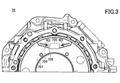
- FIG. 3 is a view of a part of the upper side of the case 70 as viewed from the rear.
- a part of the center support 80 is also shown.
- a part of the center support 80 on the upper side in the vertical direction (portion above the line P) is seen through, and the internal oil passage configuration is indicated by a dotted line.
- the lubricating structure 1 is applied to a transmission 2 for a hybrid vehicle or an electric vehicle. That is, the case 70 accommodates not only the transmission 2 but also the electric motor 3.
- the lubricating structure 1 is suitable for an arbitrary configuration including a bearing 22 and a clutch drum 26 described below or the like.
- the electric motor 3 is arbitrary, the lubricating structure 1 is suitable for the inner rotor type configuration described below.
- the electric motor 3 includes a rotating shaft 34 that is coaxial with the input shaft 24 of the transmission 2. The rotating shaft 34 is non-rotatably coupled to the input shaft 24.
- the vertical direction and the front-rear direction are defined as shown in FIG.
- the vertical direction shown in FIG. 1 represents the vertical direction (gravity direction).
- the front-rear direction corresponds to the front-rear direction of the vehicle.
- the radial direction, the circumferential direction, and the axial direction are based on the rotational axis of the input shaft 24 of the transmission 2 unless otherwise specified.
- the circumferential direction refers to the circumferential direction around the input shaft 24 of the transmission 2
- the inner diameter side refers to the side closer to the rotation axis in the radial direction of the rotation axis.
- Lubrication structure 1 includes a case 70 and a center support 80.
- the case 70 accommodates the transmission 2, the electric motor 3, the center support 80, and the like inside.
- the case 70 is formed by casting aluminum or the like, for example.
- the case 70 includes a center support fixing part 700.
- the center support fixing part 700 extends in the circumferential direction on the outer diameter side of the input shaft 24 of the transmission 2 in a manner extending from the inner peripheral surface 72 of the case 70 toward the inner diameter side.
- the center support fixing portion 700 extends in the circumferential direction over the entire circumference of the inner peripheral surface 72 of the case 70.
- the case 70 accommodates the transmission 2 on the rear side of the center support fixing portion 700 and accommodates the electric motor 3 on the front side of the center support fixing portion 700. That is, the center support fixing part 700 divides the inside of the case 70 forward and backward, the electric motor 3 is accommodated in the space on the front side of the case 70, and the transmission 2 is accommodated in the space on the rear side of the case 70.
- the center support fixing part 700 has a cavity 701 having a circular cross section around the rotation axis. That is, the center support fixing portion 700 has a ring shape when viewed in the axial direction. A center support 80 is press-fitted into the cavity 701.
- the front surface of the center support fixing portion 700 includes a seat surface 702, an oil reservoir forming surface 703, an oil guide surface 704, and a step surface (rib) 706.
- the seat surface 702 is formed around the cavity 701 in the circumferential direction.
- the normal direction of the seating surface 702 corresponds to the axial direction.
- the seat surface 702 is provided over the entire circumference except the upper side in the vertical direction.
- the center support fixing portion 700 is fastened by the center support 80 and the bolt 90 in the region of the seating surface 702.
- the normal direction corresponds to the axial direction.
- the oil reservoir forming surface 703 may have a normal direction inclined with respect to the axial direction or may include a curved surface.
- the oil reservoir forming surface 703 is formed in the same plane as the seating surface 702. The function of the oil reservoir forming surface 703 will be described later.
- the oil guide surface 704 is formed in the region above the center support fixing portion 700 in the vertical direction. As shown in FIG. 2, the oil guide surface 704 is formed in a region on the upper side in the vertical direction in the circumferentially extending region of the front surface of the center support fixing portion 700. As shown in FIG. 1, the oil guide surface 704 is formed offset from the seat surface 702 to the rear side. That is, the oil guide surface 704 forms a recess on the front surface of the center support fixing portion 700.
- the oil guide surface 704 extends to the inner peripheral surface 72 on the outer diameter side, and extends to the oil reservoir forming surface 703 on the inner diameter side. The function of the oil guide surface 704 will be described later.
- a hole 705 is formed in the oil guide surface 704.
- the hole 705 passes through the center support fixing portion 700 in the axial direction.
- the hole 705 may be formed on the lower side in the vertical direction of the oil guide surface 704.
- the shape and size of the hole 705 are arbitrary.
- the step surface 706 extends in the axial direction and absorbs an axial offset between the oil guide surface 704 and the seat surface 702. That is, the oil guide surface 704 and the seat surface 702 are continuous in the circumferential direction via the step surface 706.
- the step surface 706 is formed on both sides of the oil guide surface 704 in the circumferential direction.
- the step surfaces 706 on both sides in the circumferential direction of the oil guide surface 704 are formed so as to approach each other toward the inner diameter side (downward in the vertical direction).
- the oil guide surface 704 is formed in such a manner that the distance in the circumferential direction between the two step surfaces 706 on both sides in the circumferential direction becomes smaller as it goes toward the inner diameter side (that is, a sector shape).
- the function of the step surface 706 will be described later.
- the rear surface of the center support fixing part 700 may include a basic surface 707, a rear oil guide surface 708 offset from the basic surface 707 to the front side, and a rear step surface 709. Similar to the oil guide surface 704, the rear oil guide surface 708 is formed on the upper side in the vertical direction. That is, the rear oil guide surface 708 is substantially formed on the back side of the oil guide surface 704. In this case, the hole 705 is located in the rear oil guide surface 708 as shown in FIG. As shown in FIG. 3, the rear step surface 709 may be formed so as to be absorbed by the inner diameter side end portion of the hole 705.
- the center support 80 is pressed into the center support fixing portion 700 in the axial direction from the front side.
- the center support 80 is fastened to the center support fixing portion 700 with bolts 90.
- the center support 80 includes a main body portion 82, a flange portion 84, and a motor shaft support portion 86.
- the main body 82 has a cylindrical shape.
- the main body 82 forms a portion (a portion to be press-fitted) behind the seat surface 702 in the center support 80.
- the main body portion 82 rotatably supports the input shaft 24 of the transmission 2 on the inner diameter side.
- the main body 82 has an enlarged diameter portion 821 at the front end.
- the outer diameter of the enlarged diameter portion 821 substantially matches the diameter of the cavity 701.
- the bearing 22 is disposed on the outer peripheral portion of the rear surface of the enlarged diameter portion 821. That is, the bearing 22 is disposed between the outer peripheral portion of the rear surface of the enlarged diameter portion 821 and the clutch drum 26 in the axial direction.
- the outer diameter side of the bearing 22 is in contact with the center support fixing portion 700 in the radial direction.
- the flange portion 84 extends to the outer diameter side from the enlarged diameter portion 821.
- the flange portion 84 includes a first flange portion 841 and a second flange portion 842.
- 1st flange part 841 contacts the bearing surface 702 of the center support fixing
- the first flange portion 841 is formed with a hole through which the bolt 90 is inserted.
- the second flange portion 842 is formed on the upper side in the vertical direction as shown in FIG.
- the second flange portion 842 faces the oil reservoir forming surface 703 while being separated in the axial direction. Both end portions in the circumferential direction of the second flange portion 842 are absorbed by the first flange portion 841. That is, the second flange portion 842 gradually approaches the oil reservoir forming surface 703 toward both ends in the circumferential direction, contacts the seat surface 702, and transitions to the first flange portion 841.
- the oil reservoir 50 is formed between the second flange portion 842 and the oil reservoir forming surface 703 in the axial direction.
- the oil reservoir 50 is formed such that the upper side in the vertical direction opens. In the example shown in FIG. 1, the oil reservoir 50 has a bottom surface 52 near the outer diameter position of the enlarged diameter portion 821.
- the motor shaft support portion 86 is formed on the inner diameter side of the flange portion 84.
- the motor shaft support portion 86 rotatably supports the rotating shaft 34 of the electric motor 3 via the bearing 36.
- the oil passage 900 is formed in the center support fixing portion 700.
- the oil passage 900 is formed on the lower side in the vertical direction of the enlarged diameter portion 821 of the center support fixing portion 700.
- An oil supply source (not shown) is connected to the oil passage 900.
- the oil flows upward in the oil passage 900.
- the oil passage 900 is connected to an oil passage 902 extending in the axial direction.
- the oil passage 902 is formed in the main body portion 82.
- the oil passage 902 has a discharge part 904 on the outer diameter side.
- the oil is supplied from the discharge unit 904 to the components of the transmission 2 by centrifugal force. Note that the oil discharged from the discharge unit 904 is mainly supplied to components on the rear side of the clutch drum 26 among the components of the transmission 2.
- the oil passage 910 is disposed on the upper side in the vertical direction in the case 70.
- the oil passage 910 is in the form of a tube extending in the axial direction, but the oil passage 910 may be formed in the case 70.
- An oil supply source (not shown) is connected to the oil passage 910.
- the oil flows through the oil passage 910 toward the rear side.
- the oil passage 910 has a discharge part 912 at the end.
- the discharge part 912 is located above the oil reservoir part 50 in the vertical direction.
- the discharge part 912 overlaps the coil end 38 of the electric motor 3 in the axial direction. That is, the discharge part 912 is opposed to the outer diameter side of the coil end 38 in the radial direction.
- the oil from the discharge part 912 is supplied to components (mainly the coil end 38) on the inner diameter side of the discharge part 912 by gravity.
- the oil passage 920 is formed in the input shaft 24. A plurality of oil passages 920 may be formed. Oil is supplied to the oil passage 920 through the oil passage 900.
- the oil passage 920 has a discharge part 922 on the outer diameter side. The oil is supplied from the discharge unit 922 to the components of the transmission 2 by centrifugal force. Note that the oil discharged from the discharge unit 922 is mainly supplied to components behind the clutch drum 26 among the components of the transmission 2.
- the discharge part 930 is formed in the rotating shaft 34 of the electric motor 3.
- the discharge part 930 extends in the radial direction and communicates with the oil passage 920 in the input shaft 24 on the inner diameter side.
- the discharge unit 930 overlaps the coil end 38 of the electric motor 3 in the axial direction. That is, the discharge unit 930 faces the inner diameter side of the coil end 38 in the radial direction.
- Oil is supplied from the oil passage 920 to the discharge unit 930.
- the oil is supplied from the discharge unit 930 to the component (mainly the coil end 38) on the outer diameter side of the discharge unit 930 by centrifugal force.
- the oil passage 940 is formed in the center support 80.
- the oil passage 940 is formed above the center support 80 in the vertical direction.
- the oil passage 940 has one end opened in the oil reservoir 50 and the other end opened in the space S between the clutch drum 26 and the center support 80 in the axial direction.
- the space S is located on the rear side of the rear side surface of the diameter-expanded portion 821 and on the front side of the clutch drum 26.
- the oil passage 940 includes a first oil passage portion 942a and a second oil passage portion 942b.
- One end of the first oil passage portion 942a is opened at the lowest portion of the oil reservoir 50, and extends in an oblique direction toward the inner diameter side and the rear side.
- the first oil passage portion 942a preferably extends to the inner diameter side of the bearing 22 as shown in FIG.
- the second oil passage portion 942b is connected to the other end of the first oil passage portion 942a.
- the second oil passage portion 942 b is formed on the inner diameter side of the bearing 22.
- the second oil passage portion 942b opens in the axial direction on the rear surface of the enlarged diameter portion 821.
- the second oil passage portion 942b may extend in the circumferential direction as shown in FIG.
- the oil supplied to the oil passage 910 is dropped downward in the vertical direction via the discharge part 912, as schematically shown by the arrow R1.
- This oil is directly applied to the outer diameter side of the coil end 38 and cools the coil end 38.
- the oil used for cooling the coil end 38 in this manner is directed to the rear side in the axial direction from the coil end 38, as schematically indicated by the arrow R ⁇ b> 1, and is vertically above the front surface of the center support fixing portion 700. Hit the area.
- the guide function of the oil guide surface 704 and the step surface 706 functions, and the oil flows along the oil guide surface 704 to the oil reservoir 50 as schematically indicated by an arrow R1 (see also FIG. 2). Led.
- the oil used for cooling the coil end 38 from the oil passage 910 is recovered in the oil reservoir 50.
- the amount of oil guided to the oil reservoir 50 through the path indicated by the arrow R1 in this way increases when the rear side of the case 70 tilts downward (ie, when the vehicle tilts backward). This is because when the vehicle is tilted rearward, the front surface of the center support fixing portion 700 faces obliquely upward, and the amount of oil hitting the oil guide surface 704 increases.
- the oil supplied to the oil passage 900 is discharged from the discharge portion 930 via the oil passage 920 and the like as schematically shown by the arrow R2.
- This oil is directly applied to the inner diameter side of the coil end 38 and cools the coil end 38.
- the oil used for cooling the coil end 38 in this manner is dripped into the oil reservoir 50 on the inner diameter side of the coil end 38 by rebounding from the coil end 38. In this way, the oil used for cooling the coil end 38 from the oil passage 920 is recovered in the oil reservoir 50.
- the amount of oil guided to the oil reservoir 50 through the path of the arrow R2 in this way increases when the rear side of the case 70 is tilted downward (that is, when the vehicle is tilted backward). This is because oil that rebounds in front of the coil end 38 can also be collected in the oil reservoir 50 when the vehicle is tilted backward.
- a part of the oil supplied to the oil passage 900 and supplied to the lubrication and cooling of each component of the transmission 2 is on the outer diameter side of the clutch drum 26 as schematically shown by an arrow R3 on the upper side in the vertical direction.
- This oil travels along the outer peripheral surface of the clutch drum 26, reaches the front side of the clutch drum 26, and hits the region on the upper side in the vertical direction on the rear side surface of the center support fixing portion 700.
- the guide functions of the rear oil guide surface 708 and the rear step surface 709 function, and the oil travels along the rear oil guide surface 708 as schematically shown by an arrow R3 (see also FIG. 3).
- the oil passes through the hole 705 of the center support fixing part 700 and reaches the front surface of the center support fixing part 700, and reaches the oil reservoir 50 on the lower side in the vertical direction at the outlet (front side) of the hole 705 by gravity. In this way, a part of the oil supplied for lubrication / cooling of each component of the transmission 2 is collected in the oil reservoir 50.
- the amount of oil guided to the oil reservoir 50 through the path indicated by the arrow R3 in this way increases when the front side of the case 70 is inclined downward (that is, when the vehicle is inclined forward). This is because when the vehicle is tilted forward, the rear surface of the center support fixing portion 700 faces obliquely upward, hits the rear oil guide surface 708, and the amount of oil reaching the oil reservoir 50 increases.
- the oil in the oil reservoir 50 reaches the space S through the oil passage 940 due to gravity, as schematically indicated by the arrow R4. At this time, the oil in the oil reservoir 50 reaches the rear side of the center support 80 and the inner diameter side of the bearing 22 through the oil passage 940. This oil hits the outer diameter side bearing 22 by centrifugal force and is used for lubrication of the bearing 22.
- the oil in the oil reservoir 50 is mainly oil recovered through the paths indicated by the arrows R1 to R3 described above, but actually, the oil in the oil reservoir 50 through other paths. Oil is also included.
- a comparative configuration in which oil is directly supplied from the oil passage 900 to the inner peripheral side of the bearing 22 is also conceivable.
- the amount of oil flowing from the oil passage 900 toward the inner peripheral side of the bearing 22 increases, and the amount of oil to be supplied to each component of the transmission 2 via the oil passages 902, 920, etc.
- oil is not supplied directly from the oil passage 900 to the inner peripheral side of the bearing 22, but in other routes (see arrows R1 to R4). It becomes possible to supply the required amount of oil to the bearing 22. This makes it possible to supply a necessary amount of oil to each component of the transmission 2 including the bearing 22.
- oil can be supplied to the bearing 22 through the path indicated by the arrow R3, so that a necessary amount of oil is supplied to the bearing 22 even when the vehicle is tilted forward. Is possible. This is effective in that the reduction in the amount of oil can be compensated because the amount of oil reaching the oil reservoir 50 is reduced along the path indicated by the arrows R1 and R2 when the vehicle is tilted forward.
- drive coupling refers to a state where two rotating elements are coupled so as to be able to transmit a driving force, and the two rotating elements are coupled so as to rotate integrally, Or the state where the said 2 rotation element was connected so that a driving force could be transmitted via the 1 or 2 or more power transmission member is included.
- FIG. 4 is a skeleton diagram showing a schematic configuration of the vehicle drive device
- FIG. 5 is a velocity diagram of the vehicle drive device
- FIG. 6 is an engagement table of the transmission device TM.
- the vehicle drive device includes a first motor MG1, an input member I drivingly connected to the internal combustion engine EN, an output member O drivingly connected to the wheels W, a second motor MG2, A differential gear device PG0 and a transmission device TM are provided.
- the second motor MG2 corresponds to the electric motor 3 described with respect to the lubricating structure 1 described above
- the transmission TM corresponds to the transmission 2 described with respect to the lubricating structure 1 described above.
- the differential gear device PG0 includes a first rotating element RE11, a second rotating element RE12, and a third rotating element RE13 in the order of arrangement in the velocity diagram, and the first rotating element RE11 has a first rotating element RE11.
- the motor MG1 is drivingly connected
- the internal combustion engine EN is drivingly connected to the second rotating element RE12 via the input member I
- the second motor MG2 and the intermediate input member IM are drivingly connected to the third rotating element RE13.
- the transmission TM includes a plurality of engagement devices C1, B1,... And according to the engagement state of the plurality of engagement devices C1, B1,. ..
- the intermediate input member IM corresponds to the input shaft 24 in the description related to the lubricating structure 1 described above.
- the internal combustion engine EN is a heat engine that is driven by the combustion of fuel.
- various known internal combustion engines such as a gasoline engine and a diesel engine can be used.
- an engine output shaft Eo such as a crankshaft of the internal combustion engine EN is drivingly connected to the input member I.
- the differential gear device PG0 includes a first rotating element RE11, a second rotating element RE12, and a third rotating element RE13 in the arrangement order in the velocity diagram.
- the differential gear device PG0 is composed of a single pinion type planetary gear device, and has three rotating elements: a carrier CA0 that supports a plurality of pairs of pinion gears, a sun gear S0 that meshes with the pinion gears, and a ring gear R0 that meshes with the pinion gears.
- the sun gear S0 is the first rotation element RE11
- the carrier CA0 is the second rotation element RE12
- the ring gear R0 is the third rotation element RE13.
- the first rotating element RE11 (sun gear S0) of the differential gear device PG0 is drivingly connected so as to rotate integrally with the first motor MG1.
- the second rotating element RE12 (carrier CA0) of the differential gear device PG0 is drivingly connected via the input member I so as to rotate integrally with the internal combustion engine EN.
- the third rotating element RE13 (ring gear R0) of the differential gear device PG0 is drivingly connected so as to rotate integrally with the second motor MG2 and the intermediate input member IM.
- the differential gear device PG0 changes the balance of the rotational speeds of the rotating elements, thereby changing the speed ratio Kpg (hereinafter referred to as the differential gear) which is the ratio of the rotational speed ⁇ e of the internal combustion engine EN to the rotational speed ⁇ im of the intermediate input member IM. It is possible to function as a continuously variable transmission that can change the gear ratio Kpg of the device PG0 infinitely.
- the first motor MG1 includes a stator St1 fixed to a case CS that accommodates a vehicle drive device, and a rotor Ro1 that is rotatably supported radially inward at a position corresponding to the stator St1. .
- the rotor Ro1 of the first motor MG1 is drivingly connected so as to rotate integrally with the first rotating element RE11 (sun gear S0) of the differential gear device PG0.
- First motor MG1 is electrically connected to a battery serving as a power storage device via an inverter that performs DC / AC conversion.
- the first motor MG1 fulfills a function as a motor (electric motor) that generates power by receiving power supply and a function as a generator (generator) that generates power by receiving power supply.
- the first motor MG1 receives power supplied from the battery via the inverter and powers, or generates electric power by the rotational driving force transmitted from the internal combustion engine EN and the wheels W, and the generated electric power passes through the inverter. Is stored in the battery.
- the second motor MG2 includes a stator St2 fixed to the case CS that accommodates the vehicle drive device, and a rotor Ro2 that is rotatably supported radially inward at a position corresponding to the stator St2. .
- the rotor Ro2 of the second motor MG2 is drivingly connected so as to rotate integrally with the third rotating element RE13 (ring gear R0) of the differential gear device PG0 and the intermediate input member IM.
- Second motor MG2 is electrically connected to a battery as a power storage device via an inverter that performs DC / AC conversion.
- the second motor MG2 fulfills a function as a motor (electric motor) that generates power by receiving power supply and a function as a generator (generator) that generates power by receiving power supply. Is possible. That is, the second motor MG2 receives power supplied from the battery via the inverter and performs power running, or generates electric power by the rotational driving force transmitted from the internal combustion engine EN and the wheels W, and the generated electric power passes through the inverter. Is stored in the battery.
- the transmission device TM is drivingly connected to the intermediate input member IM.
- the transmission apparatus TM is a stepped automatic transmission apparatus having a plurality of shift stages having different speed ratios.
- the transmission device TM includes a gear mechanism such as a planetary gear device and a plurality of engagement devices C1, B1,.
- the transmission TM shifts the rotational speed ⁇ im of the intermediate input member IM at the gear ratio Ktm of each gear, converts the torque, and transmits the torque to the output member O.
- the torque transmitted from the transmission device TM to the output member O is distributed and transmitted to the left and right axles via the output differential gear device DF, and is transmitted to the wheels W that are drivingly connected to the respective axles.
- the speed ratio Ktm of the transmission apparatus TM is a ratio of the rotational speed ⁇ im of the intermediate input member IM to the rotational speed ⁇ o of the output member O when each shift stage is formed in the transmission apparatus TM.
- a torque To that is obtained by multiplying a torque Tim (hereinafter referred to as a shift input torque Tim) transmitted from the intermediate input member IM to the transmission TM by a speed ratio Ktm is transmitted from the transmission TM to the output member O.
- a shift output torque To Tim ⁇ Ktm
- the transmission apparatus TM includes four shift speeds (first shift speed 1st, second shift speed 2nd, third speed) having different speed ratios (reduction ratios or speed increase ratios).
- a shift stage 3rd and a fourth shift stage 4th) are provided as forward shift stages.
- the transmission TM includes a gear mechanism including a first planetary gear device PG1 and a second planetary gear device PG2, and six engagement devices C1, C2, C3, B1, B2, F1.
- the rotation state of each rotation element of the first planetary gear device PG1 and the second planetary gear device PG2 is switched.
- the transmission apparatus TM By selectively engaging the plurality of engagement devices C1, B1,..., The four shift speeds are switched.
- the transmission apparatus TM also includes a single reverse shift speed Rev.
- “ ⁇ ” indicates that each engaging device is in an engaged state
- “No mark” indicates that each engaging device is in a released state.
- the transmission apparatus TM includes a first rotation element RE21, a second rotation element RE22, a third rotation element RE23, and a fourth rotation element RE24 in the order of arrangement in the speed diagram. ing.
- the transmission TM is composed of two single-pinion type planetary gear units PG1 and PG2.
- the first planetary gear device PG1 has three rotation elements: a first carrier CA1 that supports a plurality of pairs of pinion gears, a first sun gear S1 that meshes with the pinion gear, and a first ring gear R1 that meshes with the pinion gear.
- the second planetary gear device PG2 has three rotational elements: a second carrier CA2 that supports a plurality of pairs of pinion gears, a second sun gear S2 that meshes with the pinion gear, and a second ring gear R2 that meshes with the pinion gear.
- the first carrier CA1 of the first planetary gear device PG1 and the second ring gear R2 of the second planetary gear device PG2 are drivingly connected to form a rotating element that rotates integrally.
- the first ring gear R1 of the first planetary gear device PG1 and the second carrier CA2 of the second planetary gear device PG2 are drivingly connected to form a rotating element that rotates integrally.
- the second sun gear S2 is the first rotating element RE21, and the first ring gear R1 and the second carrier CA2 that rotate integrally are the second rotating element RE22, and the first carrier CA1 and the second carrier CA1 that rotate integrally are the second rotating gear RE22.
- the ring gear R2 is a third rotating element RE23, and the first sun gear S1 is a fourth rotating element RE24.
- the first rotating element RE21 (second sun gear S2) of the transmission TM is drivingly connected to the third rotating element RE13 (ring gear R0) of the differential gear device PG0 via the first clutch C1.
- the second rotating element RE22 (first ring gear R1 and second carrier CA2) of the transmission apparatus TM is drivingly connected to the output member O.
- the third rotating element RE23 (first carrier CA1 and second ring gear R2) of the transmission TM is drivingly connected to the third rotating element RE13 (ring gear R0) of the differential gear device PG0 via the second clutch C2.
- the case CS is selectively fixed to the case CS as a non-rotating member via the second brake B2 or the one-way clutch F1.
- the fourth rotation element RE24 (first sun gear S1) of the transmission TM is selectively fixed to the case CS as a non-rotating member via the first brake B1, and is also differentially geared via the third clutch C3. Drive-connected to the third rotating element RE13 (ring gear R0) of the device PG0.
- the vertical axis corresponds to the rotational speed of each rotating element. That is, “0” described corresponding to the vertical axis indicates that the rotation speed is zero, the upper side is positive rotation (rotation speed is positive), and the lower side is negative rotation (rotation speed is negative). is there.
- Each of the plurality of vertical lines arranged in parallel corresponds to each rotation element of the differential gear device PG0 and each rotation element of the transmission device TM. That is, “RE11 (S0)”, “RE12 (CA0)”, and “RE13 (R0)” described above the vertical lines are respectively the first rotation element RE11 (sun gear S0) of the differential gear device PG0.
- “ ⁇ ” indicates that the engaging device connected to each rotating element is in an engaged state.
- “C1”, “C2”, “C3”, “B1”, “B2”, etc., described adjacent to each “ ⁇ ” indicate the engaged devices in the engaged state.
- “ ⁇ ” indicates the state of the rotational speed of the second rotating element RE22 (the first ring gear R1 and the second carrier CA2) of the transmission TM coupled to the output member O. It should be noted that “1st”, “2nd”, “3rd”, “4th”, “Rev”, etc. described adjacent to each “ ⁇ ” indicate the shift speeds to be formed.
- the output of the internal combustion engine EG is drivingly connected to the intermediate input member IM of the transmission TM via the differential gear device PG0. Therefore, depending on the use situation, the rotational speed of the internal combustion engine EG increases and is input to the transmission TM, and the intermediate input member IM has a rotational speed significantly higher than that of the normal transmission TM (for example, the rotation of the internal combustion engine EG). Rotate at about 1.3 times the speed).
- oil is efficiently recovered in the oil reservoir 50 through three paths indicated by arrows R1 to R3. Of the three paths indicated by arrows R1 to R3, An oil passage configuration that forms any one route, or an oil passage configuration that forms two paths in any combination may be omitted.
- the electric motor 3 is housed in the case 70, but the electric motor 3 may be omitted. That is, the configuration of the above-described embodiment can be applied entirely or partially to a transmission in a vehicle that is not a hybrid vehicle or an electric vehicle. In this case, for example, the oil passage configuration that forms the route indicated by the arrow R2 among the three routes indicated by the arrows R1 to R3 may be omitted.
- the oil reservoir 50 is formed by the center support 80 and the center support fixing portion 700 (oil reservoir forming surface 703), but may be formed only by the center support 80. That is, a surface corresponding to the oil reservoir forming surface 703 may be formed on the center support 80.
- the transmission 2 is arranged on the rear side of the center support fixing portion 700.
- the present invention can be applied to a configuration in which the transmission 2 is arranged on the front side of the center support fixing portion 700, for example. It is.
- a center support fixing portion 700 extending from the inner peripheral surface 72 to the inner diameter side is provided.
- a lubricating structure for the transmission 2 which is formed in the center support 80 and includes an oil passage 940 having one end opened in the oil reservoir 50 and having the other end opened in the space between the clutch drum 26 and the center support 80 in the axial direction.
- the oil can be efficiently collected in the oil reservoir 50 whose upper side in the vertical direction is opened, and the clutch is axially connected via the oil passage 940 that opens in the oil reservoir 50. Oil can be supplied to the space between the drum 26 and the center support 80. Thereby, the bearing 22 provided between the clutch drum 26 and the center support 80 in the axial direction can be efficiently lubricated.
- the transmission 2 according to (1) including an oil passage 910 having a discharge portion 912 vertically above the oil reservoir 50, and the discharge portion 912 overlaps the oil reservoir 50 in the axial direction.
- the oil dripped from the oil passage 910 can be efficiently collected in the oil reservoir 50. Accordingly, the bearing 22 can be efficiently lubricated using the oil on the first side of the center support fixing portion 700 in the axial direction of the transmission 2.
- the oil reservoir 50 is disposed on the inner diameter side of the coil end 38 of the motor 3 and overlaps with the coil end 38 of the motor 3 in the axial direction, and the lubricating structure 1 for the transmission 2 according to (1) or (2). .
- the oil used for cooling the coil end 38 of the motor 3 can be efficiently collected in the oil reservoir 50.
- the bearing 22 can be efficiently lubricated using the oil used for cooling the coil end 38 of the motor 3.
- Lubrication structure 1 is formed vertically above one end of the oil passage 940 in the center support fixing portion 700 and penetrates in the axial direction.
- oil on the first side of the center support fixing portion 700 in the axial direction of the transmission 2 (oil used for lubrication of the transmission 2) is stored in the oil reservoir through the hole 705.
- the parts 50 can be efficiently collected.
- the bearing 22 can be efficiently lubricated by using oil used for lubricating the transmission 2 or the like.
- the lubricating structure 1 for the transmission 2 according to any one of (1) to (4), wherein the other end of the oil passage 940 opens toward the inner diameter side of the bearing 22.
- the center support 80 includes a flange portion 84 that extends in the circumferential direction around the input shaft 24 of the transmission 2 while overlapping with the center support fixing portion 700 in the radial direction.
- the flange portion 84 is formed on the first flange portion 841 contacting the center support fixing portion 700 in the axial direction and on the upper side in the vertical direction of the extending range in the circumferential direction.
- a second flange portion 842 that is spaced apart, The oil reservoir 50 is formed between the second flange portion 842 of the center support 80 and the center support fixing portion 700, and the lubricating structure of the transmission 2 according to any one of (1) to (5) 1.
- the oil reservoir 50 can be formed using a part in the circumferential direction of the flange portion of the center support 80 (portion on the upper side in the vertical direction).
- a surface on the second side of the center support fixing portion 700 in the axial direction of the center support fixing portion 700 extends around the input shaft 24 of the transmission 2 in the circumferential direction,
- the surface on the second side of the center support fixing portion 700 is A seating surface 702 in axial contact with the center support 80;
- An oil guide surface 704 that is offset to the first side in the axial direction with respect to the seat surface 702, and is formed on the upper side in the vertical direction in the circumferential extension range;
- the lubricating structure 1 for the transmission 2 according to any one of (1) to (6), including an axial step surface 706 formed between the seat surface 702 and the oil guide surface 704.
- the amount of oil flowing into the oil reservoir 50 can be efficiently increased by using the second-side surface of the center support fixing portion 700.
- the oil can be guided from a wide range in the circumferential direction to the oil reservoir 50, and the amount of oil that can be recovered by the oil reservoir 50 can be increased efficiently.
- It includes a hole 705 that is formed vertically above one end of the oil passage 940 in the center support fixing portion 700 and penetrates in the axial direction.
- the hole 705 is formed in the oil guide surface 704,
- the oil reservoir 50 is the lubricating structure 1 of the transmission 2 according to (7), which is located on the lower side in the vertical direction than the oil guide surface 704.
- the transmission 2 is included in the vehicle drive device 100,
- the differential gear device PG0 includes a first rotation element (S0), a second rotation element element (CA0), and a third rotation element element (R0) in the order of the velocity diagram, and the first rotation element (S0) includes a first rotation element (S0).
- the motor MG1 is drivingly connected, the internal combustion engine EG is drivingly connected to the second rotating element (CA0), and the second motor MG2 and the input shaft 24 of the transmission 2 are drivingly connected to the third rotating element (R0).
- a lubricating structure 1 of a transmission 2 according to any one of (9).
- the input shaft 24 has a high rotational speed (for example, about 1 of the rotational speed of the internal combustion engine EG). Even when applied to the vehicle drive device 100 that rotates at a speed of 3 times, oil can be stably supplied to the bearing 22 regardless of the rotational speed of the input shaft 24.
Landscapes
- Engineering & Computer Science (AREA)
- General Engineering & Computer Science (AREA)
- Mechanical Engineering (AREA)
- Chemical & Material Sciences (AREA)
- Combustion & Propulsion (AREA)
- Transportation (AREA)
- General Details Of Gearings (AREA)
Abstract
Description
センタサポート固定部(700)に圧入され、変速機(2)のインプットシャフト(24)を回転可能に支持し、変速機(2)のクラッチドラム(26)を回転可能に支持するセンタサポート(80)と、
軸方向でクラッチドラム(26)とセンタサポート(80)の間に設けられるベアリング(22)と、
センタサポート(80)における軸方向でセンタサポート固定部(700)の第2側であって、第1側とは反対側の第2側に形成され、鉛直方向上側が開口した油溜部(50)と、
センタサポート(80)に形成され、油溜部(50)に一端が開口し、軸方向でクラッチドラム(26)とセンタサポート(80)の間の空間に他端が開口する油路(940)とを含む、変速機(2)の潤滑構造(1)が提供される。
(1)変速機2のインプットシャフト24の軸方向を径方向及び周方向の中心としたとき、内周面72から内径側に延在するセンタサポート固定部700を備え、変速機2の軸方向でセンタサポート固定部700の第1側に変速機2を収容するケース70と、
センタサポート固定部700に圧入され、変速機2のインプットシャフト24を回転可能に支持し、変速機2のクラッチドラム26を回転可能に支持するセンタサポート80と、
軸方向でクラッチドラム26とセンタサポート80の間に設けられるベアリング22と、
センタサポート80における軸方向でセンタサポート固定部700の第2側であって、第1側とは反対側の第2側に形成され、鉛直方向上側が開口した油溜部50と、
センタサポート80に形成され、油溜部50に一端が開口し、軸方向でクラッチドラム26とセンタサポート80の間の空間に他端が開口する油路940とを含む、変速機2の潤滑構造1。
(2)油溜部50よりも鉛直方向上側に吐出部912を有する油路910を備え、吐出部912は、軸方向で油溜部50とオーバーラップする、(1)に記載の変速機2の潤滑構造1。
(3)軸方向でセンタサポート固定部700の第2側でケース70に収容され、変速機2のインプットシャフト24と同軸の回転軸34を備えるモータ3を更に含み、
油溜部50は、モータ3のコイルエンド38の内径側に配置され、軸方向でモータ3のコイルエンド38とオーバーラップする、(1)又は(2)に記載の変速機2の潤滑構造1。
(4)センタサポート固定部700における油路940の一端よりも鉛直方向上側に形成され、軸方向に貫通する穴705を含む、(1)~(3)のうちのいずれかに記載の変速機2の潤滑構造1。
(5)油路940の他端は、ベアリング22よりも内径側で開口する、(1)~(4)のうちのいずれかに記載の変速機2の潤滑構造1。
(6)センタサポート80は、センタサポート固定部700と径方向でオーバーラップしつつ変速機2のインプットシャフト24まわりに周方向に延在するフランジ部84を備え、
フランジ部84は、センタサポート固定部700に軸方向に接触する第1フランジ部841と、周方向の延在範囲のうちの鉛直方向上側に形成され、センタサポート固定部700に対して軸方向で離間する第2フランジ部842とを含み、
油溜部50は、センタサポート80の第2フランジ部842とセンタサポート固定部700との間に形成される、(1)~(5)のうちのいずれかに記載の変速機2の潤滑構造1。
(7)センタサポート固定部700における軸方向でセンタサポート固定部700の第2側の表面は、変速機2のインプットシャフト24まわりに周方向に延在し、
センタサポート固定部700の第2側の表面は、
センタサポート80と軸方向に接触する座面702と、
座面702よりも軸方向で第1側にオフセットした油ガイド面704であって、周方向の延在範囲のうちの鉛直方向上側に形成される油ガイド面704と、
座面702と油ガイド面704との間に形成される軸方向の段差面706とを含む、(1)~(6)のうちのいずれか1項に記載の変速機2の潤滑構造1。
(8)油ガイド面704は、内径側に行くにつれて周方向両側の2つの段差面706間の周方向の距離が小さくなる態様で形成される、(7)に記載の変速機2の潤滑構造1。
(9)センタサポート固定部700における油路940の一端よりも鉛直方向上側に形成され、軸方向に貫通する穴705を含み、
穴705は、油ガイド面704に形成され、
油溜部50は、油ガイド面704よりも鉛直方向下側に位置する、(7)に記載の変速機2の潤滑構造1。
(10)変速機2は、車両用駆動装置100に含まれ、
車両用駆動装置100は、変速機2に加えて、第1モータMG1と、第2モータMG2(=モータ3)と、差動歯車装置PG0とを含み、
差動歯車装置PG0は、速度線図の順に第1回転要素(S0)、第2回転要素素(CA0)及び第3回転要素素(R0)を含み、第1回転要素(S0)に第1モータMG1が駆動連結され、第2回転要素(CA0)に内燃機関EGが駆動連結され、第3回転要素(R0)に、第2モータMG2及び変速機2のインプットシャフト24が駆動連結される、(1)~(9)のうちのいずれかに記載の変速機2の潤滑構造1。
2 変速機
3 電気モータ
22 ベアリング
24 インプットシャフト
26 クラッチドラム
34 回転軸
38 コイルエンド
50 油溜部
70 ケース
700 センタサポート固定部
702 座面
703 油溜形成面
704 油ガイド面
705 穴
706 段差面
72 内周面
80 センタサポート
84 フランジ部
841 第1フランジ部
842 第2フランジ部
910 油路
912 吐出部
940 油路
Claims (11)
- 変速機のインプットシャフトの軸方向を径方向及び周方向の中心としたとき、内周面から内径側に延在するセンタサポート固定部を備え、軸方向で前記センタサポート固定部の第1側に変速機を収容するケースと、
前記センタサポート固定部に圧入され、前記変速機のインプットシャフトを回転可能に支持し、前記変速機のクラッチドラムを回転可能に支持するセンタサポートと、
軸方向で前記クラッチドラムと前記センタサポートの間に設けられるベアリングと、
前記センタサポートにおける軸方向で前記センタサポート固定部の第2側であって、前記第1側とは反対側の第2側に形成され、鉛直方向上側が開口した油溜部と、
前記センタサポートに形成され、前記油溜部に一端が開口し、軸方向で前記クラッチドラムと前記センタサポートの間の空間に他端が開口する油路とを含む、変速機の潤滑構造。 - 前記油溜部よりも鉛直方向上側に吐出部を有する油供給路を備え、前記吐出部は、軸方向で前記油溜部とオーバーラップする、請求項1に記載の変速機の潤滑構造。
- 前記変速機は、車両用駆動装置に含まれ、
前記車両用駆動装置は、前記変速機に加えて、第1モータと、第2モータと、差動歯車装置とを含み、
前記差動歯車装置は、速度線図の順に第1回転要素、第2回転要素及び第3回転要素を含み、前記第1回転要素に前記第1モータが駆動連結され、前記第2回転要素に内燃機関が駆動連結され、前記第3回転要素に、前記第2モータ及び前記変速機のインプットシャフトが駆動連結される、請求項1又は2に記載の変速機の潤滑構造。 - 軸方向で前記センタサポート固定部の第2側で前記ケースに収容され、前記変速機のインプットシャフトと同軸の回転軸を備えるモータを更に含み、
前記油溜部は、前記モータのコイルエンドの内径側に配置され、軸方向で前記モータのコイルエンドとオーバーラップする、請求項1又は2に記載の変速機の潤滑構造。 - 前記変速機は、車両用駆動装置に含まれると共に、前記モータは、第2モータとして前記車両用駆動装置に含まれ、
前記車両用駆動装置は、前記変速機及び前記第2モータに加えて、第1モータと、差動歯車装置とを含み、
前記差動歯車装置は、速度線図の順に第1回転要素、第2回転要素及び第3回転要素を含み、前記第1回転要素に前記第1モータが駆動連結され、前記第2回転要素に内燃機関が駆動連結され、前記第3回転要素に、前記第2モータ及び前記変速機のインプットシャフトが駆動連結される、請求項4に記載の変速機の潤滑構造。 - 前記センタサポート固定部における前記油路の前記一端よりも鉛直方向上側に形成され、軸方向に貫通する穴を含む、請求項1~5のうちのいずれか1項に記載の変速機の潤滑構造。
- 前記油路の他端は、前記ベアリングよりも内径側で開口する、請求項1~6のうちのいずれか1項に記載の変速機の潤滑構造。
- 前記センタサポートは、前記センタサポート固定部と径方向でオーバーラップしつつ前記変速機のインプットシャフトまわりに周方向に延在するフランジ部を備え、
前記フランジ部は、前記センタサポート固定部に軸方向に接触する第1フランジ部と、周方向の延在範囲のうちの鉛直方向上側に形成され、前記センタサポート固定部に対して軸方向で離間する第2フランジ部とを含み、
前記油溜部は、前記センタサポートの前記第2フランジ部と前記センタサポート固定部との間に形成される、請求項1~7のうちのいずれか1項に記載の変速機の潤滑構造。 - 前記センタサポート固定部の第2側の表面は、前記変速機のインプットシャフトまわりに周方向に延在し、
前記センタサポート固定部の第2側の表面は、
前記センタサポートと軸方向に接触する座面と、
前記座面よりも軸方向で前記第1側にオフセットした油ガイド面であって、周方向の延在範囲のうちの鉛直方向上側に形成される油ガイド面と、
前記座面と前記油ガイド面との間に形成される軸方向の段差面とを含む、請求項1~8のうちのいずれか1項に記載の変速機の潤滑構造。 - 前記油ガイド面は、内径側に行くにつれて周方向両側の2つの前記段差面間の周方向の距離が小さくなる態様で形成される、請求項9に記載の変速機の潤滑構造。
- 前記センタサポート固定部における前記油路の前記一端よりも鉛直方向上側に形成され、軸方向に貫通する穴を含み、
前記穴は、前記油ガイド面に形成され、
前記油溜部は、前記油ガイド面よりも鉛直方向下側に位置する、請求項9に記載の変速機の潤滑構造。
Priority Applications (4)
| Application Number | Priority Date | Filing Date | Title |
|---|---|---|---|
| US15/126,882 US9945472B2 (en) | 2014-04-02 | 2015-03-30 | Lubricating structure for transmission |
| DE112015000919.1T DE112015000919B4 (de) | 2014-04-02 | 2015-03-30 | Schmieraufbau für ein Getriebe |
| CN201580016847.1A CN106133401B (zh) | 2014-04-02 | 2015-03-30 | 变速器的润滑构造 |
| JP2016511891A JP6235701B2 (ja) | 2014-04-02 | 2015-03-30 | 変速機の潤滑構造 |
Applications Claiming Priority (2)
| Application Number | Priority Date | Filing Date | Title |
|---|---|---|---|
| JP2014-076136 | 2014-04-02 | ||
| JP2014076136 | 2014-04-02 |
Publications (1)
| Publication Number | Publication Date |
|---|---|
| WO2015152169A1 true WO2015152169A1 (ja) | 2015-10-08 |
Family
ID=54240491
Family Applications (1)
| Application Number | Title | Priority Date | Filing Date |
|---|---|---|---|
| PCT/JP2015/059977 Ceased WO2015152169A1 (ja) | 2014-04-02 | 2015-03-30 | 変速機の潤滑構造 |
Country Status (5)
| Country | Link |
|---|---|
| US (1) | US9945472B2 (ja) |
| JP (1) | JP6235701B2 (ja) |
| CN (1) | CN106133401B (ja) |
| DE (1) | DE112015000919B4 (ja) |
| WO (1) | WO2015152169A1 (ja) |
Cited By (1)
| Publication number | Priority date | Publication date | Assignee | Title |
|---|---|---|---|---|
| CN115929891A (zh) * | 2022-12-28 | 2023-04-07 | 徐州徐工传动科技有限公司 | 一种润滑油道和压力油道分置布局的变速箱 |
Families Citing this family (8)
| Publication number | Priority date | Publication date | Assignee | Title |
|---|---|---|---|---|
| DE102017203541B3 (de) | 2017-03-03 | 2018-06-21 | Audi Ag | Antriebsvorrichtung und Kraftfahrzeug mit einer Antriebsvorrichtung |
| JP6879191B2 (ja) * | 2017-12-20 | 2021-06-02 | トヨタ自動車株式会社 | 車両の潤滑油供給装置 |
| DE102018210950A1 (de) * | 2018-07-04 | 2020-01-09 | Zf Friedrichshafen Ag | Getriebe sowie Kraftfahrzeug |
| DE102019202447A1 (de) * | 2019-02-22 | 2020-08-27 | Zf Friedrichshafen Ag | Getriebewelle, Getriebe und Kraftfahrzeug-Antriebsstrang |
| KR102857475B1 (ko) * | 2020-09-03 | 2025-09-08 | 현대자동차주식회사 | 차량의 하이브리드 파워트레인 냉각구조 |
| CN118107365B (zh) * | 2020-11-30 | 2025-04-08 | 比亚迪股份有限公司 | 轮边驱动总成和车辆 |
| CN114370494B (zh) * | 2022-01-17 | 2024-05-31 | 上海电气集团股份有限公司 | 汽车减速箱以及汽车 |
| CN115596822A (zh) * | 2022-09-23 | 2023-01-13 | 陕西法士特齿轮有限责任公司(Cn) | 一种混合动力装置及混合动力液力自动变速器 |
Citations (6)
| Publication number | Priority date | Publication date | Assignee | Title |
|---|---|---|---|---|
| JPS5771898U (ja) * | 1980-10-20 | 1982-05-01 | ||
| JPS6059721U (ja) * | 1983-09-28 | 1985-04-25 | 富士通株式会社 | 線材の外被焼き工具 |
| JPS6474359A (en) * | 1987-09-15 | 1989-03-20 | Hino Motors Ltd | Self lubricating device for rotary shaft |
| JPH0331994U (ja) * | 1989-08-03 | 1991-03-28 | ||
| JP2008232287A (ja) * | 2007-03-20 | 2008-10-02 | Toyota Motor Corp | 潤滑構造及び車両用駆動装置 |
| JP2013096560A (ja) * | 2011-11-04 | 2013-05-20 | Aisin Aw Co Ltd | 動力伝達装置 |
Family Cites Families (7)
| Publication number | Priority date | Publication date | Assignee | Title |
|---|---|---|---|---|
| JPS60172049U (ja) | 1984-04-23 | 1985-11-14 | 本田技研工業株式会社 | 歯車伝動系におけるアイドル歯車の潤滑装置 |
| JPH03123148U (ja) | 1990-03-28 | 1991-12-16 | ||
| JP2003063263A (ja) * | 2001-08-24 | 2003-03-05 | Honda Motor Co Ltd | ハイブリッド車両の動力伝達装置 |
| JP3891348B2 (ja) * | 2002-12-27 | 2007-03-14 | アイシン・エィ・ダブリュ株式会社 | 電動駆動装置 |
| JP4274117B2 (ja) | 2004-12-21 | 2009-06-03 | トヨタ自動車株式会社 | 車両用駆動装置 |
| JP5297473B2 (ja) * | 2011-02-04 | 2013-09-25 | アイシン・エィ・ダブリュ株式会社 | 車両用駆動装置 |
| DE112012000684T5 (de) * | 2011-03-31 | 2013-11-28 | Aisin Aw Co., Ltd. | Leistungsübertragungseinrichtung |
-
2015
- 2015-03-30 US US15/126,882 patent/US9945472B2/en active Active
- 2015-03-30 JP JP2016511891A patent/JP6235701B2/ja active Active
- 2015-03-30 DE DE112015000919.1T patent/DE112015000919B4/de active Active
- 2015-03-30 CN CN201580016847.1A patent/CN106133401B/zh active Active
- 2015-03-30 WO PCT/JP2015/059977 patent/WO2015152169A1/ja not_active Ceased
Patent Citations (6)
| Publication number | Priority date | Publication date | Assignee | Title |
|---|---|---|---|---|
| JPS5771898U (ja) * | 1980-10-20 | 1982-05-01 | ||
| JPS6059721U (ja) * | 1983-09-28 | 1985-04-25 | 富士通株式会社 | 線材の外被焼き工具 |
| JPS6474359A (en) * | 1987-09-15 | 1989-03-20 | Hino Motors Ltd | Self lubricating device for rotary shaft |
| JPH0331994U (ja) * | 1989-08-03 | 1991-03-28 | ||
| JP2008232287A (ja) * | 2007-03-20 | 2008-10-02 | Toyota Motor Corp | 潤滑構造及び車両用駆動装置 |
| JP2013096560A (ja) * | 2011-11-04 | 2013-05-20 | Aisin Aw Co Ltd | 動力伝達装置 |
Cited By (1)
| Publication number | Priority date | Publication date | Assignee | Title |
|---|---|---|---|---|
| CN115929891A (zh) * | 2022-12-28 | 2023-04-07 | 徐州徐工传动科技有限公司 | 一种润滑油道和压力油道分置布局的变速箱 |
Also Published As
| Publication number | Publication date |
|---|---|
| DE112015000919T5 (de) | 2016-11-03 |
| CN106133401B (zh) | 2018-07-20 |
| US20170114885A1 (en) | 2017-04-27 |
| JP6235701B2 (ja) | 2017-11-22 |
| US9945472B2 (en) | 2018-04-17 |
| DE112015000919B4 (de) | 2019-05-16 |
| JPWO2015152169A1 (ja) | 2017-04-13 |
| CN106133401A (zh) | 2016-11-16 |
Similar Documents
| Publication | Publication Date | Title |
|---|---|---|
| JP6235701B2 (ja) | 変速機の潤滑構造 | |
| JP6182438B2 (ja) | 車両用駆動伝達装置 | |
| JP2011214715A (ja) | 車両用駆動装置 | |
| JP5239814B2 (ja) | 回転電機の潤滑油供給装置 | |
| JP4234947B2 (ja) | 油圧発生装置用の駆動装置 | |
| JP6457787B2 (ja) | ハイブリッド車両用変速装置 | |
| CN103847497B (zh) | 用于混合动力车辆的动力传动系统 | |
| CN103328244A (zh) | 车辆驱动装置 | |
| CN101337500A (zh) | 车辆用驱动系统的控制设备 | |
| EP3832161A1 (en) | Vehicular driving apparatus | |
| JPWO2018181352A1 (ja) | 車両用駆動装置 | |
| US20150031488A1 (en) | Vehicle drive device | |
| WO2015022853A1 (ja) | 車両用駆動装置 | |
| JP2014052065A (ja) | 遊星歯車機構の潤滑構造 | |
| US20130220072A1 (en) | Bearing locking mechanism | |
| JP2015034593A (ja) | トランスアクスル | |
| EP3933229B1 (en) | Vehicle drive device | |
| JP2014015962A (ja) | 車両用駆動装置 | |
| JP6302294B2 (ja) | 車両用駆動装置 | |
| JP5699409B2 (ja) | 電動駆動装置 | |
| EP3862206B1 (en) | Hybrid vehicle | |
| JP5747383B2 (ja) | 動力伝達装置 | |
| JP2011122661A (ja) | 円錐摩擦リング式無段変速装置 | |
| JP5240066B2 (ja) | 車両の駆動装置 | |
| JP2018017247A (ja) | 動力伝達装置のギヤ装置 |
Legal Events
| Date | Code | Title | Description |
|---|---|---|---|
| 121 | Ep: the epo has been informed by wipo that ep was designated in this application |
Ref document number: 15773869 Country of ref document: EP Kind code of ref document: A1 |
|
| ENP | Entry into the national phase |
Ref document number: 2016511891 Country of ref document: JP Kind code of ref document: A |
|
| WWE | Wipo information: entry into national phase |
Ref document number: 112015000919 Country of ref document: DE |
|
| WWE | Wipo information: entry into national phase |
Ref document number: 15126882 Country of ref document: US |
|
| 122 | Ep: pct application non-entry in european phase |
Ref document number: 15773869 Country of ref document: EP Kind code of ref document: A1 |