WO2015152004A1 - 多原色表示装置 - Google Patents
多原色表示装置 Download PDFInfo
- Publication number
- WO2015152004A1 WO2015152004A1 PCT/JP2015/059427 JP2015059427W WO2015152004A1 WO 2015152004 A1 WO2015152004 A1 WO 2015152004A1 JP 2015059427 W JP2015059427 W JP 2015059427W WO 2015152004 A1 WO2015152004 A1 WO 2015152004A1
- Authority
- WO
- WIPO (PCT)
- Prior art keywords
- pixel
- sub
- primary color
- luminance
- signal
- Prior art date
- Legal status (The legal status is an assumption and is not a legal conclusion. Google has not performed a legal analysis and makes no representation as to the accuracy of the status listed.)
- Ceased
Links
Images








Classifications
-
- H—ELECTRICITY
- H04—ELECTRIC COMMUNICATION TECHNIQUE
- H04N—PICTORIAL COMMUNICATION, e.g. TELEVISION
- H04N9/00—Details of colour television systems
- H04N9/64—Circuits for processing colour signals
- H04N9/67—Circuits for processing colour signals for matrixing
-
- G—PHYSICS
- G09—EDUCATION; CRYPTOGRAPHY; DISPLAY; ADVERTISING; SEALS
- G09G—ARRANGEMENTS OR CIRCUITS FOR CONTROL OF INDICATING DEVICES USING STATIC MEANS TO PRESENT VARIABLE INFORMATION
- G09G5/00—Control arrangements or circuits for visual indicators common to cathode-ray tube indicators and other visual indicators
- G09G5/02—Control arrangements or circuits for visual indicators common to cathode-ray tube indicators and other visual indicators characterised by the way in which colour is displayed
-
- G—PHYSICS
- G02—OPTICS
- G02F—OPTICAL DEVICES OR ARRANGEMENTS FOR THE CONTROL OF LIGHT BY MODIFICATION OF THE OPTICAL PROPERTIES OF THE MEDIA OF THE ELEMENTS INVOLVED THEREIN; NON-LINEAR OPTICS; FREQUENCY-CHANGING OF LIGHT; OPTICAL LOGIC ELEMENTS; OPTICAL ANALOGUE/DIGITAL CONVERTERS
- G02F2201/00—Constructional arrangements not provided for in groups G02F1/00 - G02F7/00
- G02F2201/52—RGB geometrical arrangements
-
- G—PHYSICS
- G09—EDUCATION; CRYPTOGRAPHY; DISPLAY; ADVERTISING; SEALS
- G09G—ARRANGEMENTS OR CIRCUITS FOR CONTROL OF INDICATING DEVICES USING STATIC MEANS TO PRESENT VARIABLE INFORMATION
- G09G2300/00—Aspects of the constitution of display devices
- G09G2300/04—Structural and physical details of display devices
- G09G2300/0439—Pixel structures
- G09G2300/0452—Details of colour pixel setup, e.g. pixel composed of a red, a blue and two green components
-
- G—PHYSICS
- G09—EDUCATION; CRYPTOGRAPHY; DISPLAY; ADVERTISING; SEALS
- G09G—ARRANGEMENTS OR CIRCUITS FOR CONTROL OF INDICATING DEVICES USING STATIC MEANS TO PRESENT VARIABLE INFORMATION
- G09G2320/00—Control of display operating conditions
- G09G2320/06—Adjustment of display parameters
- G09G2320/0626—Adjustment of display parameters for control of overall brightness
-
- G—PHYSICS
- G09—EDUCATION; CRYPTOGRAPHY; DISPLAY; ADVERTISING; SEALS
- G09G—ARRANGEMENTS OR CIRCUITS FOR CONTROL OF INDICATING DEVICES USING STATIC MEANS TO PRESENT VARIABLE INFORMATION
- G09G2320/00—Control of display operating conditions
- G09G2320/06—Adjustment of display parameters
- G09G2320/0666—Adjustment of display parameters for control of colour parameters, e.g. colour temperature
-
- G—PHYSICS
- G09—EDUCATION; CRYPTOGRAPHY; DISPLAY; ADVERTISING; SEALS
- G09G—ARRANGEMENTS OR CIRCUITS FOR CONTROL OF INDICATING DEVICES USING STATIC MEANS TO PRESENT VARIABLE INFORMATION
- G09G2320/00—Control of display operating conditions
- G09G2320/06—Adjustment of display parameters
- G09G2320/0673—Adjustment of display parameters for control of gamma adjustment, e.g. selecting another gamma curve
-
- G—PHYSICS
- G09—EDUCATION; CRYPTOGRAPHY; DISPLAY; ADVERTISING; SEALS
- G09G—ARRANGEMENTS OR CIRCUITS FOR CONTROL OF INDICATING DEVICES USING STATIC MEANS TO PRESENT VARIABLE INFORMATION
- G09G2340/00—Aspects of display data processing
- G09G2340/06—Colour space transformation
Definitions
- the present invention relates to a multi-primary color display device.
- one pixel is constituted by three sub-pixels that display red, green, and blue, which are the three primary colors of light, thereby enabling color display.
- the conventional display device has a problem that a displayable color range (referred to as a “color reproduction range”) is narrow.
- a displayable color range referred to as a “color reproduction range”
- it is impossible to display a part of the object color the colors of various objects existing in nature; see Non-Patent Document 1). Therefore, in order to widen the color reproduction range of the display device, a method of increasing the number of primary colors used for display has been proposed.
- Patent Document 1 discloses a display device that performs display using six primary colors.
- Patent Document 1 also discloses a display device that performs display using four primary colors and a display device that performs display using five primary colors.
- An example of a display device that performs display using the six primary colors is shown in FIG.
- one pixel P is constituted by the red sub-pixel R, the green sub-pixel G, the blue sub-pixel B, the cyan sub-pixel C, the magenta sub-pixel M, and the yellow sub-pixel Ye.
- color display is performed by mixing the six primary colors red, green, blue, cyan, magenta, and yellow displayed by the six sub-pixels.
- a display device that performs display using four or more primary colors is referred to as a “multi-primary color display device”, and a display device that performs display using three primary colors (that is, a conventional general) is referred to as “three primary colors”. It is referred to as a “display device”.
- Patent Document 2 proposes a technique for displaying an image with the same or higher resolution in a multi-primary color display device without reducing the subpixel size as compared with the three primary color display device.
- a plurality of sub-pixels SP1 to SP6 constituting one pixel P are a plurality of virtual pixels (hereinafter referred to as “virtual pixels”). It is possible to distribute the display to VP1 and VP2 and display each virtual pixel as a display unit.
- FIG. 18 shows a signal conversion circuit 920 included in the multi-primary color display device 900 of Patent Document 2.
- the signal conversion circuit 920 includes a low-frequency multi-primary color signal generation unit 921, a high-frequency luminance signal generation unit 922, and a rendering processing unit 923.
- the signal conversion circuit 920 further includes a ⁇ correction unit 924 and an inverse ⁇ correction unit 925.
- the input image signal to the signal conversion circuit 920 is first subjected to ⁇ correction processing by the ⁇ correction unit 924.
- the image signal subjected to the ⁇ correction processing is input to the low-frequency multi-primary color signal generation unit 921 and the high-frequency luminance signal generation unit 922, respectively.
- the low-frequency multi-primary color signal generation unit 921 generates a low-frequency multi-primary color signal based on the input image signal.
- the low-frequency multi-primary color signal is a signal in which low-frequency components (components having a relatively low spatial frequency) of the input image signal are converted into multi-primary colors (that is, converted so as to correspond to four or more primary colors). .
- the low-frequency multi-primary color signal generation unit 921 includes a low-frequency component extraction unit (low-pass filter: LPF) 926 and a multi-primary color conversion unit 927.
- the low pass filter 926 extracts a low frequency component from the input image signal.
- the low-frequency component of the input image signal extracted by the low-pass filter 926 is converted into multi-primary colors by the multi-primary color conversion unit 927.
- the multi-primary low-frequency component is output as a low-frequency multi-primary color signal.
- the high frequency luminance signal generation unit 922 generates a high frequency luminance signal based on the input image signal.
- the high frequency luminance signal is a signal obtained by luminance conversion of a high frequency component (component having a relatively high spatial frequency) of the input image signal.
- the high frequency luminance signal generation unit 922 includes a luminance conversion unit 928 and a high frequency component extraction unit (high bus filter: HPF) 929.
- the luminance conversion unit 928 performs luminance conversion on the input image signal to generate a luminance signal.
- the high pass filter 929 extracts the high frequency component of the luminance signal generated by the luminance conversion unit 928 as a high frequency luminance signal.
- the rendering processing unit 923 converts the low-frequency multi-primary color signal generated by the low-frequency multi-primary color signal generation unit 921 and the high-frequency luminance signal generated by the high-frequency luminance signal generation unit 922 to a plurality of virtual pixels. Perform the rendering process.
- the rendering processing unit 923 includes a storage unit 923a that stores a weighting factor that defines a distribution pattern of a plurality of subpixels to a plurality of virtual pixels, and selects a preferable weighting factor according to the resolution of the input image and the like.
- the rendering process is performed in accordance with the distribution pattern defined by the selected weight coefficient.
- the image signal generated by the rendering process is subjected to inverse ⁇ correction by the inverse ⁇ correction unit 925 and output as a multi-primary color image signal.
- the signal conversion circuit 920 performs multi-primary color processing on the low frequency components of the input image signal and performs luminance conversion processing on the high frequency components.
- An image signal (multi-primary color image signal) corresponding to the four primary colors can be output by combining the low-frequency multi-primary color signal and the high-frequency luminance signal obtained by these processes and rendering to a virtual pixel.
- the magnitude relationship between the luminances of the two pixels may be reversed between the input side and the output side.
- the luminance of the virtual pixels for performing display corresponding to the pixels in the odd-numbered columns even though the pixels in the odd-numbered columns indicate black and the pixels in the even-numbered columns indicate halftone chromatic colors.
- the luminance of the virtual pixel for performing display corresponding to the pixels in the even-numbered columns may be higher.
- this phenomenon may be referred to as “luminance reversal phenomenon”.
- the present invention has been made in view of the above problems, and an object of the present invention is to provide a multi-primary color display device capable of improving the resolution by display using virtual pixels, on the input side and the output side as described above. This is to prevent the occurrence of the luminance reversal phenomenon.
- a multi-primary color display device has a pixel composed of a red sub-pixel, a green sub-pixel, a blue sub-pixel, and a yellow sub-pixel, and uses four primary colors of red, green, blue, and yellow.
- a multi-primary color display device performing color display, wherein each pixel has the red sub-pixel, the green sub-pixel, the blue sub-pixel, and the yellow sub-pixel, and an input image signal corresponding to three primary colors
- a signal conversion circuit that converts the image signal into a multi-primary color image signal corresponding to the four primary colors, and the red sub-pixel, the green sub-pixel, the blue sub-pixel, and the yellow sub-pixel constituting the pixel are converted into two
- the two virtual pixels can be displayed by allocating to the virtual pixels and adjacent two pixels in the input image can be displayed, and the signal conversion circuit can generate a low frequency component of the input image signal based on the input image signal.
- a low-frequency multi-primary color signal generation unit that generates a low-frequency multi-primary color signal that is a multi-primary signal, and a signal obtained by luminance-converting a high-frequency component of the input image signal based on the input image signal
- a high-frequency luminance signal generating unit that generates a high-frequency luminance signal
- a rendering processing unit that performs rendering processing on the two virtual pixels based on the low-frequency multi-primary color signal and the high-frequency luminance signal.
- the low-frequency multi-primary color signal generator generates absolute luminance of the red sub-pixel and absolute luminance of the green sub-pixel when one of the two adjacent pixels in the input image indicates a specific color.
- the low-frequency component can be multi-primary so that the ratio of the absolute luminance of the yellow sub-pixel to the sum is 0.5 or more and 2.0 or less.
- the specific color is a chromatic color
- the standardized luminance of blue is a color larger than 1/3 of the larger of the normalized luminance of red and the normalized luminance of green. is there.
- the low-frequency multi-primary color signal generator generates a sum of absolute luminance of the red sub-pixel and absolute luminance of the green sub-pixel when the one pixel in the input image indicates the specific color.
- Multiple primary colors can be formed so that the absolute luminance ratio of the yellow sub-pixel is substantially 1.
- the low-frequency multi-primary color signal generation unit is configured to view a color represented by the low-frequency multi-primary color signal from the front direction.
- Multiple primary colors can be made so that 1/2 is 0.03 or less.
- the specific color is a dark skin
- the low-frequency multi-primary color signal generator generates a color represented by the low-frequency multi-primary color signal when the one pixel in the input image indicates a dark skin.
- the specified primary color difference ⁇ u′v ′ ((u′ ⁇ u 60 ′) 2 + (v′ ⁇ v 60 ′) 2 ) can be converted to multiple primary colors so that 1/2 is 0.03 or less.
- the specific color is a light skin
- the low-frequency multi-primary color signal generator generates a color represented by the low-frequency multi-primary color signal when the one pixel in the input image indicates a light skin.
- the other pixel when the one of the two adjacent pixels in the input image shows a specific color, the other pixel shows black.
- each of the two virtual pixels is composed of two or more subpixels of the red subpixel, the green subpixel, the blue subpixel, and the yellow subpixel.
- a plurality of the pixels are arranged in a matrix including a plurality of rows and a plurality of columns, and the red sub-pixel, the green sub-pixel, and the blue sub-pixel are respectively included in the plurality of pixels.
- the yellow sub-pixels are arranged in one row and four columns.
- the multi-primary color display device according to the present invention is a liquid crystal display device.
- the multi-primary color display device includes a pixel composed of a red sub-pixel, a green sub-pixel, a blue sub-pixel, and a yellow sub-pixel, and has four primary colors of red, green, blue, and yellow.
- a multi-primary color display device that performs color display using a multi-primary color display panel having the red sub-pixel, the green sub-pixel, the blue sub-pixel, and the yellow sub-pixel in each pixel, and an input corresponding to three primary colors
- a signal conversion circuit that converts an image signal into a multi-primary color image signal corresponding to the four primary colors, and the red subpixel, the green subpixel, the blue subpixel, and the yellow subpixel that constitute the pixel
- the two virtual pixels can be divided and displayed for two adjacent pixels in the input image by the two virtual pixels, and the signal conversion circuit can input the input image signal based on the input image signal.
- a low-frequency multi-primary color signal generation unit that generates a low-frequency multi-primary color signal that is a signal in which the low-frequency components are converted into multi-primary colors, and the high-frequency component of the input image signal is subjected to luminance conversion based on the input image signal
- a high-frequency luminance signal generating unit that generates a high-frequency luminance signal that is a received signal; a rendering processing unit that performs rendering processing on the two virtual pixels based on the low-frequency multi-primary color signal and the high-frequency luminance signal;
- the low-frequency multi-primary color signal generation unit includes a magnitude relationship between luminances of one pixel and the other pixel of the two adjacent pixels in the input image, and a virtual pixel corresponding to the one pixel.
- the low-frequency component can be converted into multiple primary colors so that the magnitude relationship of the luminance of the virtual pixel corresponding to the other pixel is not reversed.
- a television receiver includes a multi-primary color display device having the above-described configuration.
- a driving method of a multi-primary color display device includes a pixel composed of a red sub-pixel, a green sub-pixel, a blue sub-pixel, and a yellow sub-pixel, and four primary colors of red, green, blue, and yellow
- a method for driving a multi-primary color display device that performs color display using the method (A) for converting an input image signal corresponding to three primary colors into a multi-primary color image signal corresponding to the four primary colors;
- the red sub-pixel, the green sub-pixel, the blue sub-pixel, and the yellow sub-pixel to be configured are allocated to two virtual pixels, and two adjacent pixels in the input image are displayed by the two virtual pixels (B
- the step (A) generates, based on the input image signal, a low-frequency multi-primary color signal that is a signal in which low-frequency components of the input image signal are converted into multi-primary colors (a )When, A step (b) of generating a high-frequency luminance signal, which is a signal
- a driving method of a multi-primary color display device includes a pixel composed of a red sub-pixel, a green sub-pixel, a blue sub-pixel, and a yellow sub-pixel, and four primary colors of red, green, blue, and yellow
- a multi-primary color display apparatus that performs color display using the step (A) of converting an input image signal corresponding to three primary colors into a multi-primary color image signal corresponding to the four primary colors, and the pixel constituting the pixel Distributing the red sub-pixel, the green sub-pixel, the blue sub-pixel, and the yellow sub-pixel to two virtual pixels, and performing display of two adjacent pixels in the input image by the two virtual pixels;
- the step (A) includes a step (a) of generating a low-frequency multi-primary color signal, which is a signal in which low-frequency components of the input image signal are multi-primary based on the input image signal;
- the input picture Based on the signal, the step (b) of generating a high-frequency luminance
- the multi-primary color display device that can improve the resolution by display using virtual pixels, it is to prevent the occurrence of a luminance reversal phenomenon between the input side and the output side.
- FIG. 1 is a block diagram schematically showing a liquid crystal display device (multi-primary color display device) 100 according to an embodiment of the present invention.
- 3 is a diagram illustrating an example of sub-pixel arrangement of a multi-primary color display panel 10 included in the liquid crystal display device 100.
- FIG. 3 is a diagram illustrating an example of sub-pixel arrangement of a multi-primary color display panel 10 included in the liquid crystal display device 100.
- FIG. It is a figure which shows the example of the distribution pattern of the sub pixel to two virtual pixels. It is a figure which shows the example of the distribution pattern of the sub pixel to two virtual pixels.
- 3 is a block diagram schematically showing a signal conversion circuit 20 provided in the liquid crystal display device 100.
- (A) to (l) are diagrams illustrating an example of multi-primary color conversion in a case where odd-numbered columns of pixels indicate black and even-numbered columns of pixels indicate gray (halftone achromatic color) in the input image.
- (A) to (l) are multi-primary color conversions in the case where both odd-numbered pixels and even-numbered pixels indicate dark skin in the input image (that is, when the input image is a solid image of dark skin). It is a figure which shows an example.
- (A)-(l) is a figure which shows the example of multi-primary color conversion in case the pixel of an odd number column shows black and the pixel of an even number column has shown the dark skin in the input image.
- the color reproduction range of the multi-primary color display panel 10 and the BT. 7 is a chromaticity diagram illustrating a color gamut of 709;
- FIG. (A) to (l) are diagrams illustrating an example of multi-primary color conversion in the case where odd-numbered columns of pixels indicate black and even-numbered columns of pixels indicate dark skin in the input image. The case where the combination of the sub-pixel brightness of the first embodiment is selected is shown.
- (A) to (l) are diagrams illustrating an example of multi-primary color conversion in the case where odd-numbered columns of pixels indicate black and even-numbered columns of pixels indicate dark skin in the input image. The case where the combination of the sub-pixel luminance of Example 2 is selected is shown.
- (A) to (l) are diagrams showing an example of multi-primary color conversion in the case where odd-numbered columns of pixels indicate dark skin and even-numbered columns of pixels indicate black in the input image.
- the case where the combination of the sub-pixel luminance of Example 3 is selected is shown.
- (A) to (l) are diagrams illustrating an example of multi-primary color conversion in the case where odd-numbered columns of pixels indicate black and even-numbered columns of pixels indicate dark skin in the input image.
- FIG. 9 shows a case where a combination of sub-pixel luminances in the comparative example is selected.
- (A) to (l) are diagrams illustrating an example of multi-primary color conversion in a case where odd-numbered columns of pixels indicate chromatic colors and even-numbered columns of pixels indicate black in the input image.
- FIG. 10 is a block diagram schematically showing a signal conversion circuit 920 included in the multi-primary color display device 900 of Patent Document 2.
- FIG. 10 is a block diagram schematically showing a signal conversion circuit 920 included in the multi-primary color display device 900 of Patent Document 2.
- liquid crystal display device is illustrated below, this invention is not limited to a liquid crystal display device.
- FIG. 1 shows a liquid crystal display device 100 according to this embodiment.
- the liquid crystal display device 100 includes a multi-primary color display panel 10 and a signal conversion circuit 20, and performs display using four primary colors of red, green, blue, and yellow ( 4 primary color display device).
- the multi-primary color display panel 10 has pixels composed of a red sub-pixel, a green sub-pixel, a blue sub-pixel, and a yellow sub-pixel.
- a plurality of pixels are arranged in a matrix including a plurality of rows and a plurality of columns.
- FIG. 2 shows an example of a specific pixel structure (sub-pixel arrangement) of the multi-primary color display panel 10.
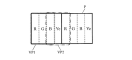
- each pixel P of the multi-primary color display panel 10 is composed of four sub-pixels. More specifically, a red sub-pixel R that displays red and a green sub-pixel that displays green G, a blue sub-pixel B that displays blue, and a yellow sub-pixel Ye that displays yellow. Within each pixel P, the red sub-pixel R, the green sub-pixel G, the blue sub-pixel B, and the yellow sub-pixel Ye are arranged in one row and four columns.
- the red sub-pixel R, the green sub-pixel G, the blue sub-pixel B, and the yellow sub-pixel Ye are arranged in this order from the left side to the right side.
- the sub-pixel arrangement is not limited to this.
- the red sub-pixel R, the green sub-pixel G, the blue sub-pixel B, and the yellow sub-pixel Ye may be arranged in this order from the right side to the left side. Good.
- the signal conversion circuit 20 converts an input image signal (three primary color image signals) corresponding to three primary colors (RGB) into an image signal corresponding to four primary colors (referred to as “multi-primary color image signal”). Convert to The multi-primary color image signal output from the signal conversion circuit 20 is input to the multi-primary color display panel 10, and color display using the four primary colors is performed. A specific configuration of the signal conversion circuit 20 will be described in detail later.
- the red sub-pixel R, the green sub-pixel G, the blue sub-pixel B, and the yellow sub-pixel Ye constituting each pixel P are divided into two virtual pixels (“first virtual pixel” and “first virtual pixel”). 2 virtual pixels ”) and display of two adjacent pixels in the input image can be performed by these two virtual pixels.
- Each of the two virtual pixels includes two or more sub-pixels among the red sub-pixel R, the green sub-pixel G, the blue sub-pixel B, and the yellow sub-pixel Ye.
- FIG. 4 shows an example of a distribution pattern of sub-pixels to two virtual pixels.
- the red sub-pixel R, the green sub-pixel G, the blue sub-pixel B, and the yellow sub-pixel Ye are distributed to two virtual pixels (first virtual pixel and second virtual pixel) VP1 and VP2.
- the first virtual pixel VP1 includes a red subpixel R, a green subpixel G, and a blue subpixel B.
- the second virtual pixel VP2 includes a blue subpixel B and a yellow subpixel Ye.
- the first virtual pixel VP1 and the second virtual pixel VP2 include a blue subpixel B as a common subpixel, and share the blue subpixel B.
- each of the first virtual pixel VP1 and the second virtual pixel VP2 is configured by two or more subpixels continuous in one pixel P. It is not limited to this.
- FIG. 5 shows another example of the distribution pattern.
- the first virtual pixel VP1 shown in FIG. 5 includes a red subpixel R, a green subpixel G, and a blue subpixel B of the left pixel P.
- the second virtual pixel VP2 includes a blue subpixel B and a yellow subpixel Ye of the left pixel P, and a red subpixel R of the right pixel P.
- the second virtual pixel VP2 is configured by a plurality of (here, three) sub-pixels that extend across the two pixels P.
- the virtual pixel may straddle the two pixels P.
- the liquid crystal display device 100 includes a plurality of sub-pixels (the red sub-pixel R, the green sub-pixel G, the blue sub-pixel B, and the yellow sub-pixel Ye) that constitute each pixel P as two virtual pixels (first sub-pixels). 1 virtual pixel VP1 and second virtual pixel VP2), and information can be displayed independently by each virtual pixel. Therefore, the display for two adjacent pixels in the input image can be performed by these two virtual pixels.
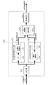
- FIG. 6 shows an example of a specific configuration of the signal conversion circuit 20.
- the signal conversion circuit 20 includes a low-frequency multi-primary color signal generation unit 21, a high-frequency luminance signal generation unit 22, and a rendering processing unit 23.
- the signal conversion circuit 20 further includes a ⁇ correction unit 24 and an inverse ⁇ correction unit 25.
- the input image signal to the signal conversion circuit 20 is first subjected to ⁇ correction processing by the ⁇ correction unit 24.
- the image signal that has been subjected to the ⁇ correction processing is input to the low-frequency multi-primary color signal generation unit 21 and the high-frequency luminance signal generation unit 22, respectively.
- the low-frequency multi-primary color signal generation unit 21 generates a low-frequency multi-primary color signal based on the input image signal.
- the low-frequency multi-primary color signal is a signal obtained by converting low-frequency components (components having a relatively low spatial frequency) of the input image signal into multi-primary colors (that is, converted so as to correspond to the four primary colors).
- the low-frequency multi-primary color signal generation unit 21 includes a low-frequency component extraction unit (here, a low-pass filter: LPF) 26 and a multi-primary color conversion unit 27.
- the low pass filter 26 extracts a low frequency component from the input image signal.
- the low-frequency component of the input image signal extracted by the low-pass filter 26 is converted into multi-primary colors by the multi-primary color conversion unit 27.
- the multi-primary low-frequency component is output as a low-frequency multi-primary color signal.
- the high frequency luminance signal generation unit 22 generates a high frequency luminance signal based on the input image signal.
- the high frequency luminance signal is a signal obtained by luminance conversion of a high frequency component (component having a relatively high spatial frequency) of the input image signal.
- the high frequency luminance signal generation unit 22 includes a luminance conversion unit 28 and a high frequency component extraction unit (here, a high-pass filter: HPF) 29.
- the luminance conversion unit 28 performs luminance conversion on the input image signal to generate a luminance signal.
- the high pass filter 29 extracts the high frequency component of the luminance signal generated by the luminance conversion unit 28 as a high frequency luminance signal.
- the rendering processing unit 23 outputs two virtual pixels based on the low-frequency multi-primary color signal generated by the low-frequency multi-primary color signal generation unit 21 and the high-frequency luminance signal generated by the high-frequency luminance signal generation unit 22. Perform the rendering process.
- the image signal generated by the rendering process is subjected to inverse ⁇ correction by the inverse ⁇ correction unit 25 and is output as a multi-primary color image signal.
- the signal conversion circuit 20 considers human visual characteristics that the sensitivity to the luminance signal is superior to the color signal (that is, the visibility of the color difference is lower than the luminance visibility), Multi-primary color processing is performed on the low-frequency component of the input image signal, and luminance conversion processing is performed on the high-frequency component.
- An image signal (multi-primary color image signal) corresponding to the four primary colors can be output by combining the low-frequency multi-primary color signal and the high-frequency luminance signal obtained by these processes and rendering to a virtual pixel.
- the low-frequency multi-primary color signal generation unit 21 satisfies the predetermined relationship between the luminance values of the red sub-pixel R, the green sub-pixel G, and the yellow sub-pixel Ye for a specific input image signal. As described above, it is possible to perform multi-primary color formation of low-frequency components. Specifically, the low frequency multi-primary color signal generation unit 21 determines the absolute luminance of the red sub-pixel R and the absolute luminance of the green sub-pixel G when one of the two adjacent pixels in the input image indicates a specific color. Multi-primary colors of low-frequency components can be obtained so that the ratio of the absolute luminance of the yellow subpixel to the luminance sum is 0.5 or more and 2.0 or less.
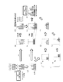
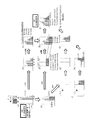
- FIG. 7 is a diagram showing an example of multi-primary color conversion in a case where odd-numbered columns of pixels indicate black and even-numbered columns of pixels indicate gray (halftone achromatic color) in the input image.
- the red, green, and blue luminances are zero for the odd-numbered pixels, and the red for the even-numbered pixels.
- Green and blue luminances are the same value greater than zero.
- the input image signal is passed through an LPF (low pass filter), and as shown in FIG. 7B, the luminance of red, green and blue is averaged by two pixels.
- LPF low pass filter
- the luminances of red, green, blue, and yellow are the same (but not zero). Multi-primary color signal) is obtained.
- a white component (corresponding to the luminance signal) corresponding to the minimum values of red, green, and blue luminance is extracted from the input image signal.
- the extracted white component is passed through an HPF (high-pass filter) and corresponds to an odd number column as shown in FIG. 7 (e) and an even number column as shown in FIG. 7 (f). Separate into minutes.
- FIGS. 7G and 7H each of the separated white components is converted into the luminance of the color of the sub-pixel constituting the corresponding virtual pixel.
- the white component corresponding to the odd number column is converted into the luminance of the color (red, green, blue) of the sub-pixel constituting the virtual pixel corresponding to the odd number column, and the white component corresponding to the even number example is converted to the even number column.
- the luminance is converted to the luminance of the color (blue, yellow, red) of the sub-pixel constituting the corresponding virtual pixel. Since the white component corresponding to the odd-numbered columns is zero, as shown in FIG. 7G, the luminance of each color after conversion is also zero. On the other hand, since the white component corresponding to the even-numbered columns is not zero, the luminance of each color after conversion is not zero as shown in FIG. Thereafter, as shown in FIG.
- the combined luminance is further combined with the low-frequency multi-primary color signal.
- the white component extracted from the input image signal is passed through the LPF (see FIG. 7 (j)) is subtracted from the low-frequency multi-primary color signal (see FIG. 7 (k)).
- the later luminance (here, zero for all colors) is added to the luminance shown in FIG.
- a multi-primary color image signal as shown in FIG. According to this multi-primary color image signal, only virtual pixels corresponding to even columns are lit. Therefore, the luminance reversal phenomenon does not occur.
- FIG. 8 is a diagram illustrating an example of multi-primary color conversion in a case where both odd-numbered pixels and even-numbered columns of pixels in the input image indicate dark skin (that is, when the input image is a solid image of dark skin). is there.
- the red, green, and blue luminances (normalized luminances) for both the odd-numbered pixels and the even-numbered pixels are predetermined values larger than zero. Value.
- the input image signal is passed through the LPF, and as shown in FIG. 8B, the luminance of red, green and blue is averaged by two pixels.
- a white component (corresponding to a luminance signal) corresponding to the minimum values of red, green, and blue luminance is extracted from the input image signal.
- the extracted white component is passed through the HPF and separated into an amount corresponding to an odd number column as shown in FIG. 8 (e) and an amount corresponding to an even number column as shown in FIG. 8 (f). To do.
- FIGS. 8G and 8H each of the separated white components is converted into the luminance of the color of the sub-pixel constituting the corresponding virtual pixel.
- the white component corresponding to the odd number column is converted into the luminance of the color (red, green, blue) of the sub-pixel constituting the virtual pixel corresponding to the odd number column, and the white component corresponding to the even number example is converted to the even number column.
- the luminance is converted to the luminance of the color (blue, yellow, red) of the sub-pixel constituting the corresponding virtual pixel. Since the white component corresponding to the odd-numbered column and the white component corresponding to the even-numbered column are not zero, as shown in FIGS. 8G and 8H, the luminance of each color after conversion is not zero. Thereafter, as shown in FIG.
- the combined luminance is further combined with the low-frequency multi-primary color signal.
- the white component extracted from the input image signal is passed through the LPF (see FIG. 8 (j)) is subtracted from the low-frequency multi-primary color signal (see FIG. 8 (k)).
- the subsequent luminance (here, red, green, and blue are positive and yellow is negative) is added to the luminance shown in FIG.
- a multi-primary color image signal as shown in FIG. According to this multi-primary color image signal, both virtual pixels corresponding to odd columns and virtual pixels corresponding to even columns are lit.
- the brightness of two adjacent pixels is the same on the input side, whereas the brightness of the two virtual pixels is greatly different on the output side.
- the red, green, blue, and yellow luminances (luminances in FIG. 8L) in the output image signal are excellent in viewing angle characteristics. Therefore, in the example shown in FIG. 8, excellent viewing angle characteristics are maintained.
- FIG. 9 is a diagram illustrating an example of multi-primary color conversion in a case where odd-numbered columns of pixels indicate black and even-numbered columns of pixels indicate dark skin in the input image.
- the red, green, and blue luminances are zero for the pixels in the odd columns, and the red for the pixels in the even columns.
- Green and blue luminances are predetermined values larger than zero.
- the input image signal is passed through the LPF, and as shown in FIG. 9B, the luminance of red, green and blue is averaged by two pixels.
- a white component (corresponding to a luminance signal) corresponding to the minimum values of red, green, and blue luminance is extracted from the input image signal.
- the extracted white component is passed through the HPF and separated into an amount corresponding to an odd number column as shown in FIG. 9 (e) and an amount corresponding to an even number column as shown in FIG. 9 (f). To do.
- FIGS. 9G and 9H each of the separated white components is converted into the luminance of the color of the sub-pixel constituting the corresponding virtual pixel.
- the white component corresponding to the odd number column is converted into the luminance of the color (red, green, blue) of the sub-pixel constituting the virtual pixel corresponding to the odd number column, and the white component corresponding to the even number example is converted to the even number column.
- the luminance is converted to the luminance of the color (blue, yellow, red) of the sub-pixel constituting the corresponding virtual pixel. Since the white component corresponding to the odd-numbered columns is zero, as shown in FIG. 9G, the luminance of each color after conversion is also zero. On the other hand, since the white component corresponding to the even-numbered column is not zero, the luminance of each color after conversion is not zero, as shown in FIG. Thereafter, as shown in FIG. 9I, these are added together.
- the combined luminance is further combined with the low-frequency multi-primary color signal.
- the white component extracted from the input image signal is passed through the LPF (see FIG. 9 (j)) is subtracted from the low-frequency multi-primary color signal (see FIG. 9 (k)).
- the subsequent luminance (here, red, green, and blue are positive and yellow is negative) is added to the luminance shown in FIG.
- a multi-primary color image signal as shown in FIG.
- both virtual pixels corresponding to odd columns and virtual pixels corresponding to even columns are lit. Further, the luminance of the virtual pixels corresponding to the odd columns is higher than the luminance of the virtual pixels corresponding to the even columns.
- the luminances of red, green, blue, and yellow in the output image signal are the viewing angles.
- the combination may not be excellent in characteristics (because it is different from the luminance in FIG. 9C), and in the example shown in FIG. 9, the viewing angle characteristic may be deteriorated.
- a high-frequency image such as a single line illustrated in FIG. 9, even if the viewing angle characteristic is bad, it does not cause a display problem (not so much).
- the low-frequency multi-primary color signal generation unit 21 performs a specific input image signal (one of the two adjacent pixels in the input image indicates a specific color). ), The primary color of the low-frequency component so that the ratio of the absolute luminance of the yellow subpixel Ye to the sum of the absolute luminance of the red subpixel R and the absolute luminance of the green subpixel G is 0.5 or more and 2.0 or less. By performing the conversion, the occurrence of the luminance reversal phenomenon as described above can be prevented.
- the low-frequency multi-primary color signal generation unit 21 performs low-frequency so that the magnitude relationship between the luminances of two adjacent pixels in the input image is not opposite to the luminance relationship between the two virtual pixels corresponding to the two pixels. Multi-primary colorization of components can be performed.
- Table 1 shows red, green, blue, yellow, and pixel P displayed by the red subpixel R, the green subpixel G, the blue subpixel B, and the yellow subpixel Ye of the multi-primary color display panel 10 of the present embodiment.
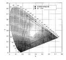
- FIG. 10 shows the color reproduction range of the multi-primary color display panel 10 of the present embodiment.
- BT A color gamut of 709 is also shown.
- Table 2 below shows BT.
- the chromaticity x, y and tristimulus values X, Y, Z of primary colors (red, green, blue) and white (D65 standard light source) at 709 are shown.
- Table 3 shows the gradations and luminances (normalized luminance) of red, green, and blue when the dark skin is represented by the three primary color image signals, and Table 4 below shows the chromaticity x, y and tristimulus of the dark skin. The values X, Y, Z are shown.
- Table 5 shows red, green, and blue gradations and luminance (normalized luminance) when the light skin is represented by the three primary color image signals.
- Table 6 shows the light skin chromaticity x, y and Tristimulus values X, Y and Z are shown.
- the chromaticity and tristimulus values of the dark skin and light skin may not be exactly the same as those exemplified in Table 4 and Table 6.
- the chromaticity of the dark skin and light skin may be It may be around 0.02 from the values exemplified in Table 6, and the Y value of the dark skin and light skin may be around 0.005 and 0.01 from the values exemplified in Table 4 and Table 6, respectively. Good.
- Table 7 shows examples (# 1 D to # 10 D ) of combinations of gradation and luminance of the red sub-pixel R, the green sub-pixel G, the blue sub-pixel B, and the yellow sub-pixel Ye for displaying the dark skin. Show.
- Table 7 shows two types of luminance, that is, normalized luminance and absolute luminance.
- the normalized luminance is the luminance normalized with the highest gradation luminance of each color as 1, and the absolute luminance is obtained by multiplying the normalized luminance by the Y value of each color.
- Table 7 also shows the ratio (R + G: Ye) of the absolute luminance of the red subpixel R and the absolute luminance of the green subpixel G and the absolute luminance of the yellow subpixel Ye for each example.
- Table 8 shows chromaticity x, y, and Y values when the dark skin is viewed from the front direction, and chromaticity x, y, and Y values when viewed from the oblique 60 ° direction.
- Table 8 shows chromaticity coordinates (u ′, v ′) indicating chromaticity when the dark skin is viewed from the front direction and chromaticity coordinates (u ′) indicating chromaticity when viewed from the oblique 60 ° direction.
- the low-frequency multi-primary color signal generation unit 21 performs the absolute luminance and green sub-pixels of the red sub-pixel R when one of the two adjacent pixels in the input image indicates a dark skin.
- the low primary component multi-primary color is formed so that the ratio of the absolute luminance of the yellow sub-pixel Ye to the sum of the absolute luminances of the pixels G is 0.5 or more and 2.0 or less. That is, of the combinations shown in Table 7, not the first and eighth to tenth combinations (# 1 D , # 8 D to # 10 D ), but the second to seventh combinations (# 2 D Multi-primary colors are selected so that .about. # 7 D ) is selected.
- Table 9 shows examples (# 1 L to # 11 L ) of combinations of gradations and luminances of the red sub-pixel R, the green sub-pixel G, the blue sub-pixel B, and the yellow sub-pixel Ye for displaying the light skin. Show. Table 9 shows two types of luminance, normalized luminance and absolute luminance. Table 9 also shows the ratio (R + G: Ye) of the absolute luminance of the red subpixel R and the absolute luminance of the green subpixel G and the absolute luminance of the yellow subpixel Ye for each example. ing.
- Table 10 shows chromaticity x, y, and Y values when the light skin is viewed from the front direction, and chromaticity x, y, and Y values when viewed from the oblique 60 ° direction.
- Table 10 shows chromaticity coordinates (u ′, v ′) indicating chromaticity when the light skin is viewed from the front direction and chromaticity coordinates (u ′) indicating chromaticity when viewed from the oblique 60 ° direction.
- the low-frequency multi-primary color signal generation unit 21 performs the absolute luminance and green sub-range of the red sub-pixel R when one of the two adjacent pixels in the input image indicates a light skin.
- the low primary component multi-primary color is formed so that the ratio of the absolute luminance of the yellow sub-pixel Ye to the sum of the absolute luminances of the pixels G is 0.5 or more and 2.0 or less. That is, of the combinations shown in Table 9, the third to ninth, not the first, second, tenth and eleventh combinations (# 1 L , # 2 L , # 10 L , # 11 L ). Multi-primary color conversion is performed so as to select the second combination (# 3 L to # 9 L ).
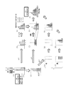
- FIG. 11 is a diagram illustrating an example of multi-primary color conversion in a case where odd-numbered columns of pixels indicate black and even-numbered columns of pixels indicate dark skin in the input image.
- the red, green, and blue luminances are zero for the odd-numbered pixels, and the red for the even-numbered pixels.
- Green and blue luminances are predetermined values larger than zero.
- the maximum value of the luminances of red, green, and blue in the even-numbered pixels is 0.123.
- the input image signal is passed through the LPF, and as shown in FIG. 11B, the luminance of red, green and blue is averaged by two pixels.
- this signal is converted into multiple primary colors (4-color conversion), as shown in FIG. 11C, the absolute luminance of the yellow sub-pixel Ye with respect to the sum of the absolute luminance of the red sub-pixel R and the absolute luminance of the green sub-pixel G.
- a multi-primary color signal low-frequency multi-primary color signal
- a white component (corresponding to a luminance signal) corresponding to the minimum values of red, green, and blue luminance is extracted from the input image signal.
- the luminance of the white component normalized luminance
- the extracted white component is passed through the HPF and separated into an amount corresponding to an odd number column as shown in FIG. 11 (e) and an amount corresponding to an even number column as shown in FIG. 11 (f). To do.
- FIGS. 11G and 11H each of the separated white components is converted into the luminance of the color of the sub-pixel constituting the corresponding virtual pixel.
- the white component corresponding to the odd number column is converted into the luminance of the color (red, green, blue) of the sub-pixel constituting the virtual pixel corresponding to the odd number column, and the white component corresponding to the even number example is converted to the even number column.
- the luminance is converted to the luminance of the color (blue, yellow, red) of the sub-pixel constituting the corresponding virtual pixel. Since the white component corresponding to the odd-numbered column is zero, as shown in FIG. 11G, the luminance of each color after conversion is also zero.
- the white components corresponding to the even columns are not zero, and as shown in FIG. 11 (h), the luminances (absolute luminances) of blue, yellow, and red after conversion are 0.024, 0.042, 0.003. Thereafter, as shown in FIG.
- the combined luminance is further combined with the low-frequency multi-primary color signal.
- the white component extracted from the input image signal is passed through the LPF (as shown in FIG. 11 (j), converted into absolute brightness of red, green, blue, and yellow, 0.007 respectively. , 0.014, 0.004, 0.019) are subtracted from the low-frequency multi-primary color signal, and the luminance after the subtraction (as shown in FIG. 11 (k), here, red, green, blue, yellow are 0 respectively) .026, 0.001, 0.001, 0.029) are added to the luminance shown in FIG.
- this multi-primary color image signal both virtual pixels corresponding to odd columns and virtual pixels corresponding to even columns are lit.
- the luminance of the virtual pixels corresponding to the even columns is higher than the luminance of the virtual pixels corresponding to the odd columns. Therefore, the luminance reversal phenomenon does not occur.
- FIG. 12 is a diagram illustrating an example of multi-primary color conversion in a case where odd-numbered columns of pixels indicate black and even-numbered columns of pixels indicate dark skin in the input image.
- the red, green, and blue luminances are zero for the odd-numbered pixels, and the red for the even-numbered pixels.
- Green and blue luminances are predetermined values larger than zero.
- the maximum value of the luminances of red, green, and blue in the even-numbered pixels is 0.123.
- the input image signal is passed through the LPF, and as shown in FIG. 12B, the luminance of red, green and blue is averaged by two pixels.
- this signal is converted into multiple primary colors (4-color conversion), as shown in FIG. 12C, the absolute luminance of the yellow sub-pixel Ye with respect to the sum of the absolute luminance of the red sub-pixel R and the absolute luminance of the green sub-pixel G.
- a white component (corresponding to a luminance signal) corresponding to the minimum values of red, green, and blue luminance is extracted from the input image signal.
- the luminance of the white component normalized luminance
- the extracted white component is passed through the HPF and separated into an amount corresponding to an odd number column as shown in FIG. 12 (e) and an amount corresponding to an even number column as shown in FIG. 12 (f). To do.
- FIGS. 12G and 12H each of the separated white components is converted into the luminance of the color of the sub-pixel constituting the corresponding virtual pixel.
- the white component corresponding to the odd number column is converted into the luminance of the color (red, green, blue) of the sub-pixel constituting the virtual pixel corresponding to the odd number column, and the white component corresponding to the even number example is converted to the even number column.
- the luminance is converted to the luminance of the color (blue, yellow, red) of the sub-pixel constituting the corresponding virtual pixel. Since the white component corresponding to the odd-numbered columns is zero, as shown in FIG. 12G, the luminance of each color after conversion is also zero.
- the white components corresponding to the even columns are not zero, and the luminances (absolute luminances) of blue, yellow, and red after conversion are 0.024, 0.042, 0.003. Thereafter, as shown in FIG.
- the combined luminance is further combined with the low-frequency multi-primary color signal.
- the white component extracted from the input image signal is passed through the LPF (as shown in FIG. 12 (j), converted into absolute luminances of red, green, blue and yellow, 0.007 respectively. , 0.014, 0.004, 0.019) are subtracted from the low-frequency multi-primary color signal, and the luminance after subtraction (as shown in FIG. 12 (k), red, green, blue, and yellow are 0 here). .029, 0.013, 0.001, 0.014) is added to the luminance shown in FIG.
- FIG. 13 is a diagram illustrating an example of multi-primary color conversion in a case where odd-numbered pixels in the input image indicate dark skin and even-numbered pixels indicate black.
- the red, green, and blue luminances are predetermined values larger than zero, For these pixels, the luminance of red, green and blue (normalized luminance) is zero.
- the maximum value of the luminances of red, green, and blue in the odd-numbered pixels is 0.123.
- the input image signal is passed through the LPF, and as shown in FIG. 13B, the luminance of red, green and blue is averaged by two pixels.
- this signal is converted into multiple primary colors (4-color conversion), as shown in FIG. 13C, the absolute luminance of the yellow subpixel Ye with respect to the sum of the absolute luminance of the red subpixel R and the absolute luminance of the green subpixel G is calculated.
- a multi-primary color signal low-frequency multi-primary color signal
- a white component (corresponding to a luminance signal) corresponding to the minimum values of red, green, and blue luminance is extracted from the input image signal.
- the luminance of the white component normalized luminance
- the extracted white component is passed through the HPF and separated into an amount corresponding to an odd number column as shown in FIG. 13 (e) and an amount corresponding to an even number column as shown in FIG. 13 (f). To do.
- FIGS. 13G and 13H each of the separated white components is converted into the luminance of the color of the sub-pixel constituting the corresponding virtual pixel.
- the white component corresponding to the odd number column is converted into the luminance of the color (red, green, blue) of the sub-pixel constituting the virtual pixel corresponding to the odd number column, and the white component corresponding to the even number example is converted to the even number column.
- the luminance is converted to the luminance of the color (blue, yellow, red) of the sub-pixel constituting the corresponding virtual pixel.
- the white components corresponding to the odd columns are not zero, and the red, green, and blue luminances (absolute luminances) after conversion are 0.012, 0.032, and 0.003, respectively, as shown in FIG. is there.
- the white component corresponding to the even-numbered columns is zero, the luminance of each color after conversion is also zero as shown in FIG. Thereafter, as shown in FIG.
- the combined luminance is further combined with the low-frequency multi-primary color signal.
- the white component extracted from the input image signal is passed through the LPF (as shown in FIG. 13 (j), converted into absolute luminances of red, green, blue, and yellow, 0.007 respectively. , 0.014, 0.004, 0.019) is subtracted from the low-frequency multi-primary color signal, and the luminance after subtraction (as shown in FIG. 13 (k), red, green, blue, and yellow are 0 here). .022, -0.011, 0.001, 0.045) are added to the luminance shown in FIG.
- this multi-primary color image signal both virtual pixels corresponding to odd columns and virtual pixels corresponding to even columns are lit.
- the brightness of the virtual pixels corresponding to the even columns is lower than the brightness of the corresponding virtual pixels. Therefore, the luminance reversal phenomenon does not occur.
- the low frequency multi-primary color signal generation unit 21 of the signal conversion circuit 20 can select the combination of the luminances of the first, second, or third embodiment, thereby preventing the occurrence of the luminance reversal phenomenon.
- FIG. 14 is a diagram illustrating an example of multi-primary color conversion in a case where odd-numbered columns of pixels indicate black and even-numbered columns of pixels indicate dark skin in the input image.
- the red, green, and blue luminances are zero for the odd-numbered pixels, and the red for the even-numbered pixels.
- Green and blue luminances are predetermined values larger than zero.
- the maximum value of the luminances of red, green, and blue in the even-numbered pixels is 0.123.
- the input image signal is passed through the LPF, and as shown in FIG. 14B, the luminance of red, green and blue is averaged by two pixels.
- this signal is converted into multiple primary colors (4-color conversion)
- the absolute luminance of the yellow subpixel Ye with respect to the sum of the absolute luminance of the red subpixel R and the absolute luminance of the green subpixel G is calculated.
- a multi-primary color signal low-frequency multi-primary color signal.
- a white component (corresponding to a luminance signal) corresponding to the minimum values of red, green, and blue is extracted from the input image signal.
- the luminance of the white component (normalized luminance) is 0.044 (about 1/3 of the maximum luminance).
- the extracted white component is passed through the HPF and separated into an amount corresponding to an odd number column as shown in FIG. 14 (e) and an amount corresponding to an even number column as shown in FIG. 14 (f). To do.
- FIGS. 14G and 14H each of the separated white components is converted into the luminance of the color of the sub-pixel constituting the corresponding virtual pixel.
- the white component corresponding to the odd number column is converted into the luminance of the color (red, green, blue) of the sub-pixel constituting the virtual pixel corresponding to the odd number column, and the white component corresponding to the even number example is converted to the even number column.
- the luminance is converted to the luminance of the color (blue, yellow, red) of the sub-pixel constituting the corresponding virtual pixel. Since the white component corresponding to the odd-numbered columns is zero, as shown in FIG. 14G, the luminance of each color after conversion is also zero.
- the white components corresponding to the even columns are not zero, and as shown in FIG. 14 (h), the luminances (absolute luminances) of blue, yellow, and red after conversion are 0.024, 0.042, 0.003. Thereafter, as shown in FIG. 14 (i), these are added together.
- the combined luminance is further combined with the low-frequency multi-primary color signal.
- the white component extracted from the input image signal is passed through the LPF (as shown in FIG. 14 (j) 0.00, converted into absolute luminances of red, green, blue, and yellow, 0.007 respectively.
- 0.014, 0.004, 0.019 is subtracted from the low-frequency multi-primary color signal, and the luminance after subtraction (as shown in FIG. 14 (k), red, green, blue, and yellow are 0 here).
- .035, 0.040, 0.001, ⁇ 0.018) are added to the luminance shown in FIG.
- the low-frequency multi-primary color signal generation unit 21 uses the red sub-pixel when one of the two adjacent pixels in the input image shows a specific color.
- the multi-primary color of the low-frequency component so that the ratio of the absolute luminance of the yellow subpixel Ye to the sum of the absolute luminance of R and the absolute luminance of the green subpixel G is 0.5 or more and 2.0 or less, It is possible to prevent the occurrence of a luminance reversal phenomenon.
- the ratio of the absolute luminance of the yellow subpixel Ye to the sum of the absolute luminance of the red subpixel R and the absolute luminance of the green subpixel G is particularly within the above range (0.5 to 2.0). It is not limited. It may be 1 (or substantially 1) as in the first embodiment, may be 0.5 as in the second embodiment, or may be 2 as in the third embodiment. If the ratio of the absolute luminance of the yellow subpixel Ye to the sum of the absolute luminance of the red subpixel R and the absolute luminance of the green subpixel G is 0.5 or more and 2.0 or less, the white component is 1/3 or more of the total luminance. The luminance reversal phenomenon does not occur for the colors of.
- FIGS. 15A to 15L are diagrams showing an example of multi-primary color conversion in a case where odd-numbered columns of pixels indicate chromatic colors and even-numbered columns of pixels indicate black in the input image.
- the relative luminance (normalized luminance) of red and green in the odd-numbered pixels is the same, and the minimum relative luminance is 1/3 with respect to the maximum relative luminance of red, green, and blue.
- An example is shown.
- the minimum value of the relative luminance becomes 1/3 or less of the maximum value
- the color component becomes 2 times or more (2/3 or more for 1/3) with respect to the white component.
- FIG. 15 shows an example in which the relative luminance of red and green is the same so that the sum of the absolute luminances of red and green becomes the largest after calculation.
- the relative luminance of red and green in the odd-numbered columns of the input image is set to 1, and when the white component is extracted as shown in FIG. (Luminance) is 0.33.
- This white component (relative luminance 0.33) is equally distributed to two pixels as shown in FIG. This assumes that when the white component is converted from relative luminance to absolute luminance, red and green and yellow are almost halved (from FIGS. 11 and 12, they are also almost halved).
- the ratio of the absolute luminance of the yellow sub-pixel Ye to the sum of the absolute luminance of the red sub-pixel R and the absolute luminance of the green sub-pixel G is preferably 2.0 or less.
- the ratio of the absolute luminance of yellow to the sum of the absolute luminance of red and the absolute luminance of green is less than 0.5, a luminance reversal phenomenon occurs. Therefore, the absolute luminance of the red subpixel R
- the ratio of the absolute luminance of the yellow sub-pixel Ye to the sum of absolute luminances of the green sub-pixel G is preferably 0.5 or more.
- the specific color indicated by one of the two adjacent pixels in the input image is the dark skin or the light skin is illustrated, but of course, the embodiment of the present invention is not limited thereto. Is not to be done.
- the specific color is typically a chromatic color, and a color whose blue standardized luminance is larger than 1/3 of the larger one of the standardized luminance of red and the standardized luminance of green ( That is, B> MAX (R, G) / 3 color).
- the dark skin is a color in which the normalized luminance of blue is larger than 1/3 of the larger of the normalized luminance of red and the normalized luminance of green (0.092> 0). .267 / 3).
- the light skin also has a color whose blue standardized luminance is larger than 1/3 of the larger one of the standardized luminance of red and the standardized luminance of green (0.311). > 0.632 / 3).
- the color indicated by the other of the two adjacent pixels in the input image is black is exemplified, but the embodiment of the present invention is not limited to this.
- the color indicated by the other pixel may be the specific color. That is, the input image may be a solid image of the specific color.
- the low-frequency multi-primary color signal generation unit 21 determines the color represented by the low-frequency multi-primary color signal from the front direction when one pixel in the input image indicates a specific color.
- the second to sixth combinations (# 2 D to # 6 D ) in Table 8 and the third to ninth combinations (# 3 L to # 9 L ) in Table 9 and Table 10 satisfy this condition. is doing.
- the low-frequency multi-primary color signal generation unit 21 determines the chromaticity when the color represented by the low-frequency multi-primary color signal is viewed from the front direction.
- the color difference ⁇ u′v ′ defined by the chromaticity coordinates (u ′, v ′) shown and the chromaticity coordinates (u 60 ′, v 60 ′) showing the chromaticity when viewed from an oblique 60 ° direction is 0. It is preferable to perform multi-primary color so as to be 03 or less.
- the second to sixth combinations (# 2 D to # 6 D ) in Tables 7 and 8 satisfy this condition.
- the low frequency multi-primary color signal generation unit 21 calculates chromaticity when the color represented by the low frequency multi-primary color signal is viewed from the front direction.
- the color difference ⁇ u′v ′ defined by the chromaticity coordinates (u ′, v ′) shown and the chromaticity coordinates (u 60 ′, v 60 ′) showing the chromaticity when viewed from an oblique 60 ° direction is 0. It is preferable to perform multi-primary color so as to be 01 or less.
- the third to ninth combinations (# 3 L to # 9 L ) in Tables 9 and 10 satisfy this condition.
- the absolute luminance of each sub-pixel can be measured by, for example, an imaging color luminance meter ProMetric® I manufactured by Radiant® Zemax.
- the multi-primary color display device can perform high-quality display, it is used in various electronic devices, and is preferably used in, for example, a television receiver.
- the television receiver includes a circuit for receiving television broadcasting in addition to the multi-primary color display device.
- the driving method of the multi-primary color display device uses a multi-primary image corresponding to the four primary colors (red, green, blue and yellow) from the input image signal corresponding to the three primary colors.
- (B) which is performed by two virtual pixels VP1 and VP2.
- Step (A) (signal conversion step) includes a step (a) (low frequency multi-primary color signal generation step) for generating a low frequency multi-primary color signal based on the input image signal, and a high frequency luminance signal based on the input image signal.
- step (B) (a high-frequency luminance signal generation step), and a step (c) (rendering processing) for rendering the two virtual pixels VP1 and VP2 based on the low-frequency multi-primary color signal and the high-frequency luminance signal Step).
- step (a) when one of the two adjacent pixels in the input image shows a specific color, the yellow subpixel Ye with respect to the sum of the absolute luminance of the red subpixel R and the absolute luminance of the green subpixel G Multiple primary colors of low-frequency components are performed so that the absolute luminance ratio is 0.5 or more and 2.0 or less.
- the low primary component multi-primary colors so that the magnitude relationship between the luminances of two adjacent pixels in the input image is not opposite to the luminance relationship between the two virtual pixels corresponding to the two pixels. It can be said that it is made.
- This specification discloses a multi-primary color display device described in the following items.
- a multi-primary color display device having a pixel composed of a red sub-pixel, a green sub-pixel, a blue sub-pixel, and a yellow sub-pixel, and performing color display using four primary colors of red, green, blue, and yellow
- a multi-primary color display panel having the red sub-pixel, the green sub-pixel, the blue sub-pixel and the yellow sub-pixel in each pixel;
- a signal conversion circuit that converts an input image signal corresponding to three primary colors into a multi-primary color image signal corresponding to the four primary colors;
- the red sub-pixel, the green sub-pixel, the blue sub-pixel, and the yellow sub-pixel constituting the pixel are divided into two virtual pixels, and display of two adjacent pixels in the input image is performed by the two virtual pixels.
- the signal conversion circuit includes: A low-frequency multi-primary color signal generation unit that generates a low-frequency multi-primary color signal based on the input image signal, wherein the low-frequency component of the input image signal is a multi-primary signal; Based on the input image signal, a high-frequency luminance signal generating unit that generates a high-frequency luminance signal that is a signal obtained by luminance conversion of the high-frequency component of the input image signal; A rendering processing unit that performs rendering processing on the two virtual pixels based on the low-frequency multi-primary color signal and the high-frequency luminance signal; The low-frequency multi-primary color signal generator generates a sum of absolute luminance of the red sub-pixel and absolute luminance of the green sub-pixel when one of the two adjacent pixels in the input image indicates a specific color.
- a multi-primary color display device capable of performing multi-primary coloration of the low-frequency component so that a ratio of absolute luminance of the yellow sub-pixel to 0.5 to 2.0 is achieved.
- the specific color is a chromatic color, and the standardized luminance of blue is a color larger than 1/3 of the larger one of the normalized luminance of red and the normalized luminance of green.
- Multi-primary color display device Multi-primary color display device.
- the low-frequency multi-primary color signal generator When the one pixel in the input image indicates the specific color, the low-frequency multi-primary color signal generator generates the yellow sub-pixel with respect to the sum of the absolute luminance of the red sub-pixel and the absolute luminance of the green sub-pixel. 3.
- the multi-primary color display device according to item 1 or 2, wherein the multi-primary color can be changed so that the absolute luminance ratio is substantially 1.
- the low-frequency multi-primary color signal generation unit is a color indicating chromaticity when the color represented by the low-frequency multi-primary color signal is viewed from the front direction.
- the color difference ⁇ u′v ′ ((u ′, v ′) and the chromaticity coordinates (u 60 ′, v 60 ′) indicating the chromaticity when viewed obliquely from 60 °. -u 60 ′) 2 + (v′ ⁇ v 60 ′) 2 )
- the multi-primary color display device according to any one of items 1 to 3, capable of performing multi-primary color so that 1/2 is 0.03 or less .
- the specific color is a dark skin;
- the multi-primary color display device according to any one of items 1 to 4, which can perform multi-primary color so that 1/2 is 0.03 or less.
- the specific color is light skin
- the low-frequency multi-primary color signal generation unit when the one pixel in the input image indicates a light skin, chromaticity coordinates indicating chromaticity when the color represented by the low-frequency multi-primary color signal is viewed from the front direction
- Color difference ⁇ u′v ′ ((u′ ⁇ u) defined by (u ′, v ′) and chromaticity coordinates (u 60 ′, v 60 ′) indicating chromaticity when viewed from an oblique 60 ° direction 60 ′) 2 + (v′ ⁇ v 60 ′) 2 )
- the multi-primary color display device according to any one of items 1 to 5, which can be multi-primary so that 1/2 is 0.01 or less.
- Each of the two virtual pixels is any one of items 1 to 7 including two or more subpixels of the red subpixel, the green subpixel, the blue subpixel, and the yellow subpixel. Multi-primary color display device.
- a plurality of the pixels are arranged in a matrix including a plurality of rows and a plurality of columns, The multi-primary color according to any one of items 1 to 8, wherein, in each of the plurality of pixels, the red sub-pixel, the green sub-pixel, the blue sub-pixel, and the yellow sub-pixel are arranged in one row and four columns. Display device.
- the multi-primary color display device according to any one of items 1 to 9, which is a liquid crystal display device.
- a multi-primary color display device having a pixel composed of a red sub-pixel, a green sub-pixel, a blue sub-pixel, and a yellow sub-pixel, and performing color display using four primary colors of red, green, blue, and yellow
- a multi-primary color display panel having the red sub-pixel, the green sub-pixel, the blue sub-pixel and the yellow sub-pixel in each pixel;
- a signal conversion circuit that converts an input image signal corresponding to three primary colors into a multi-primary color image signal corresponding to the four primary colors;
- the red sub-pixel, the green sub-pixel, the blue sub-pixel, and the yellow sub-pixel constituting the pixel are divided into two virtual pixels, and display of two adjacent pixels in the input image is performed by the two virtual pixels.
- the signal conversion circuit includes: A low-frequency multi-primary color signal generation unit that generates a low-frequency multi-primary color signal based on the input image signal, wherein the low-frequency component of the input image signal is a multi-primary signal; Based on the input image signal, a high-frequency luminance signal generating unit that generates a high-frequency luminance signal that is a signal obtained by luminance conversion of the high-frequency component of the input image signal; A rendering processing unit that performs rendering processing on the two virtual pixels based on the low-frequency multi-primary color signal and the high-frequency luminance signal;
- the low-frequency multi-primary color signal generation unit includes a magnitude relationship between luminances of one pixel and the other pixel of the two adjacent pixels in the input image, a virtual pixel corresponding to the one pixel, and the other pixel.
- a multi-primary color display device capable of performing multi-primary coloration of the low-frequency component so that the magnitude relationship of the luminance of the virtual pixels corresponding to is not reversed
- a television receiver comprising the multi-primary color display device according to any one of items 1 to 11.
- a driving method of a multi-primary color display device having pixels composed of a red sub-pixel, a green sub-pixel, a blue sub-pixel, and a yellow sub-pixel, and performing color display using four primary colors of red, green, blue, and yellow
- the red sub-pixel, the green sub-pixel, the blue sub-pixel, and the yellow sub-pixel constituting the pixel are divided into two virtual pixels, and display of two adjacent pixels in the input image is performed by the two virtual pixels.
- Step (B) The step (A) Generating a low-frequency multi-primary color signal, which is a signal obtained by converting the low-frequency components of the input image signal into multi-primary colors based on the input image signal; Generating a high-frequency luminance signal, which is a signal obtained by luminance-converting a high-frequency component of the input image signal based on the input image signal; (C) performing a rendering process on the two virtual pixels based on the low-frequency multi-primary color signal and the high-frequency luminance signal,
- the step (a) when one of the two adjacent pixels in the input image shows a specific color, the yellow with respect to the sum of the absolute luminance of the red sub-pixel and the absolute luminance of the green sub-pixel
- a multi-primary color display device having a pixel composed of a red sub-pixel, a green sub-pixel, a blue sub-pixel, and a yellow sub-pixel, and performing color display using four primary colors of red, green, blue, and yellow, A step (A) of converting an input image signal corresponding to three primary colors into a multi-primary color image signal corresponding to the four primary colors;
- the red sub-pixel, the green sub-pixel, the blue sub-pixel, and the yellow sub-pixel constituting the pixel are divided into two virtual pixels, and display of two adjacent pixels in the input image is performed by the two virtual pixels.
- Step (B) The step (A) Generating a low-frequency multi-primary color signal, which is a signal obtained by converting the low-frequency components of the input image signal into multi-primary colors based on the input image signal; Generating a high-frequency luminance signal, which is a signal obtained by luminance-converting a high-frequency component of the input image signal based on the input image signal; (C) performing a rendering process on the two virtual pixels based on the low-frequency multi-primary color signal and the high-frequency luminance signal, In the step (a), the magnitude relationship of the luminance of one pixel and the other pixel of the two adjacent pixels in the input image, the virtual pixel corresponding to the one pixel, and the other pixel A driving method of a multi-primary color display device in which the low-frequency component is converted into multiple primary colors so that the magnitude relationship of luminance of virtual pixels is not reversed.
- a multi-primary color display device capable of improving the resolution by display using virtual pixels, it is possible to prevent the occurrence of a luminance reversal phenomenon between the input side and the output side.
- the multi-primary color display device can perform high-quality display, it is suitably used for various electronic devices such as a liquid crystal television.
- Multi primary color display panel 20
- Signal conversion circuit 21
- Low frequency multi primary color signal generation part 22
- High frequency luminance signal generation part 23
- Rendering processing part 24
- ⁇ correction part 25
- Inverse ⁇ correction part 26
- Low frequency component extraction part (low-pass filter) 27
- Multi-primary color conversion unit 28
- Luminance conversion unit 29
- High-frequency component extraction unit (high-pass filter) 100 Liquid crystal display device (multi-primary color display device) P pixel R red sub-pixel G green sub-pixel B blue sub-pixel Ye yellow sub-pixel VP1 first virtual pixel VP2 second virtual pixel
Landscapes
- Engineering & Computer Science (AREA)
- Multimedia (AREA)
- Signal Processing (AREA)
- Physics & Mathematics (AREA)
- Computer Hardware Design (AREA)
- General Physics & Mathematics (AREA)
- Theoretical Computer Science (AREA)
- Controls And Circuits For Display Device (AREA)
- Control Of Indicators Other Than Cathode Ray Tubes (AREA)
- Liquid Crystal (AREA)
- Liquid Crystal Display Device Control (AREA)
- Processing Of Color Television Signals (AREA)
Abstract
多原色表示装置は、多原色表示パネルと、入力画像信号を多原色画像信号に変換する信号変換回路(20)とを備え、画素を構成する赤サブ画素、緑サブ画素、青サブ画素および黄サブ画素を2つの仮想画素に振り分け、入力画像における隣接した2画素分の表示を2つの仮想画素によって行うことができる。信号変換回路は、低域多原色信号生成部(21)を有する。低域多原色信号生成部は、入力画像における隣接した2画素のうちの一方の画素が特定の色を示す場合、赤サブ画素の絶対輝度および緑サブ画素の絶対輝度の和に対する黄サブ画素の絶対輝度の比が、0.5以上2.0以下になるように低域成分の多原色化を行う。これにより、入力画像における互いに隣接した2つの画素に着目したとき、入力側と出力側とで、2つの画素の輝度の大小関係が逆転してしまう現象の発生を防止する。
Description
本発明は、多原色表示装置に関する。
一般的な表示装置では、光の三原色である赤、緑および青を表示する3つのサブ画素によって1つの画素が構成されており、そのことによってカラー表示が可能になっている。
しかしながら、従来の表示装置は、表示可能な色の範囲(「色再現範囲」と呼ばれる。)が狭いという問題を有している。色再現範囲が狭いと、物体色(自然界に存在する様々な物体の色である;非特許文献1参照)の一部を表示することができない。そこで、表示装置の色再現範囲を広くするために、表示に用いる原色の数を増やす手法が提案されている。
例えば、特許文献1には、6つの原色を用いて表示を行う表示装置が開示されている。また、特許文献1には、4つの原色を用いて表示を行う表示装置や、5つの原色を用いて表示を行う表示装置も開示されている。6つの原色を用いて表示を行う表示装置の一例を図16に示す。図16に示す表示装置800では、赤サブ画素R、緑サブ画素G、青サブ画素B、シアンサブ画素C、マゼンタサブ画素Mおよび黄サブ画素Yeによって1つの画素Pが構成される。この表示装置800では、6つのサブ画素によって表示される赤、緑、青、シアン、マゼンタおよび黄の6つの原色を混色することにより、カラー表示が行われる。
表示に用いる原色の数を増やす、つまり、4つ以上の原色を用いて表示を行うことにより、三原色を用いて表示を行う従来の表示装置よりも色再現範囲を広くすることができる。本願明細書では、4つ以上の原色を用いて表示を行う表示装置を「多原色表示装置」と称し、3つの原色を用いて表示を行う(つまり従来の一般的な)表示装置を「三原色表示装置」と称する。
しかしながら、多原色表示装置で、三原色表示装置と同等の解像度を有する画像を表示するためには、画面サイズが同一の場合、デバイス構造の細密化が必要となり、生産コストが増大してしまう。これは、多原色表示装置では1画素あたりのサブ画素の数が3から4以上に増加するので、同一画面サイズで同一画素数を実現するためには、三原色表示装置と比べてサブ画素のサイズを小さくしなくてはならないからである。具体的には、表示に用いる原色の数をm(m≧4)とすると、サブ画素のサイズを3/mにしなくてはならない。例えば、6つの原色を用いて表示を行う多原色表示装置では、サブ画素のサイズを1/2(=3/6)にする必要がある。
そこで、多原色表示装置において、三原色表示装置と比べてサブ画素サイズを小さくすることなく、同等またはより高い解像度の画像を表示するための技術が、特許文献2に提案されている。図17に示すように、特許文献2の多原色表示装置900では、1つの画素Pを構成する複数のサブ画素SP1~SP6を、複数の仮想的な画素(以下では「仮想画素」と呼ぶ)VP1、VP2に振り分け、各仮想画素を表示単位として表示を行うことができる。
図18に、特許文献2の多原色表示装置900が備える信号変換回路920を示す。信号変換回路920は、図18に示すように、低域多原色信号生成部921と、高域輝度信号生成部922と、レンダリング処理部923とを有する。信号変換回路920は、さらに、γ補正部924と、逆γ補正部925とを有する。
信号変換回路920への入力画像信号は、まず、γ補正部924によってγ補正処理を施される。γ補正処理を施された画像信号は、次に、低域多原色信号生成部921と、高域輝度信号生成部922とにそれぞれ入力される。
低域多原色信号生成部921は、入力画像信号に基づいて、低域多原色信号を生成する。低域多原色信号は、入力画像信号の低域成分(相対的に空間周波数が低い成分)が多原色化された(つまり4つ以上の原色に対応するように変換がなされた)信号である。
低域多原色信号生成部921は、低域成分抽出部(ローパスフィルタ:LPF)926と、多原色変換部927とを有する。ローパスフィルタ926は、入力画像信号から低域成分を抽出する。ローパスフィルタ926によって抽出された入力画像信号の低域成分は、多原色変換部927によって多原色化される。多原色化された低域成分は、低域多原色信号として出力される。
高域輝度信号生成部922は、入力画像信号に基づいて、高域輝度信号を生成する。高域輝度信号は、入力画像信号の高域成分(相対的に空間周波数が高い成分)が輝度変換された信号である。
高域輝度信号生成部922は、輝度変換部928と、高域成分抽出部(ハイバスフィルタ:HPF)929とを有する。輝度変換部928は、入力画像信号を輝度変換して輝度信号を生成する。ハイパスフィルタ929は、輝度変換部928によって生成された輝度信号の高域成分を、高域輝度信号として抽出する。
レンダリング処理部923は、低域多原色信号生成部921によって生成された低域多原色信号と、高域輝度信号生成部922によって生成された高域輝度信号とに基づいて、複数の仮想画素へのレンダリング処理を行う。レンダリング処理部923は、複数の仮想画素への複数のサブ画素の振り分けパターンを規定する重み係数が格納された記憶部923aを含んでおり、入力画像の解像度等に応じて好ましい重み係数を選択し、選択された重み係数で規定される振り分けパターンに従ってレンダリング処理を行う。レンダリング処理によって生成された画像信号は、逆γ補正部925によって逆γ補正を施され、多原色画像信号として出力される。
このように、信号変換回路920では、入力画像信号の低域成分に対しては多原色化処理を行い、高域成分に対しては輝度変換処理を行う。これらの処理によって得られた低域多原色信号と高域輝度信号とを組み合わせ、仮想画素へレンダリングすることにより、4つの原色に対応した画像信号(多原色画像信号)を出力することができる。
M. R. Pointer, "The gamut of real surface colors", Color Research and Application, Vol.5, No.3, pp.145-155 (1980)
しかしながら、本願発明者の検討によれば、特許文献2に開示されている技術を単純に用いると、特定の入力画像を表示する際に、不具合が発生することがわかった。
具体的には、入力画像における互いに隣接した2つの画素に着目したとき、入力側と出力側とで、2つの画素の輝度の大小関係が逆転してしまう場合があることがわかった。例えば、入力画像では、奇数列の画素が黒を示し、偶数列の画素が中間調の有彩色を示しているにもかかわらず、奇数列の画素に対応した表示を行うための仮想画素の輝度が、偶数列の画素に対応した表示を行うための仮想画素の輝度よりも高くなってしまうことがある。以下では、この現象を、「輝度の逆転現象」と呼ぶことがある。
本発明は、上記問題に鑑みてなされたものであり、その目的は、仮想画素を用いた表示により解像度を向上させることができる多原色表示装置において、上述したような入力側と出力側とでの輝度の逆転現象の発生を防止することにある。
本発明の実施形態による多原色表示装置は、赤サブ画素、緑サブ画素、青サブ画素および黄サブ画素から構成される画素を有し、赤、緑、青および黄の4つの原色を用いてカラー表示を行う多原色表示装置であって、各画素に前記赤サブ画素、前記緑サブ画素、前記青サブ画素および前記黄サブ画素を有する多原色表示パネルと、3原色に対応した入力画像信号を前記4つの原色に対応した多原色画像信号に変換する信号変換回路と、を備え、前記画素を構成する前記赤サブ画素、前記緑サブ画素、前記青サブ画素および前記黄サブ画素を2つの仮想画素に振り分け、入力画像における隣接した2画素分の表示を前記2つの仮想画素によって行うことができ、前記信号変換回路は、前記入力画像信号に基づいて、前記入力画像信号の低域成分が多原色化された信号である低域多原色信号を生成する低域多原色信号生成部と、前記入力画像信号に基づいて、前記入力画像信号の高域成分が輝度変換された信号である高域輝度信号を生成する高域輝度信号生成部と、前記低域多原色信号および前記高域輝度信号に基づいて、前記2つの仮想画素へのレンダリング処理を行うレンダリング処理部と、を有し、前記低域多原色信号生成部は、前記入力画像における前記隣接した2画素のうちの一方の画素が特定の色を示す場合、前記赤サブ画素の絶対輝度および前記緑サブ画素の絶対輝度の和に対する前記黄サブ画素の絶対輝度の比が、0.5以上2.0以下になるように前記低域成分の多原色化を行い得る。
ある実施形態において、前記特定の色は、有彩色であり、且つ、青の規格化輝度が、赤の規格化輝度および緑の規格化輝度のうちの大きい方の1/3よりも大きい色である。
ある実施形態において、前記低域多原色信号生成部は、前記入力画像における前記一方の画素が前記特定の色を示す場合、前記赤サブ画素の絶対輝度および前記緑サブ画素の絶対輝度の和に対する前記黄サブ画素の絶対輝度の比が、実質的に1になるように多原色化を行い得る。
ある実施形態において、前記低域多原色信号生成部は、前記入力画像における前記一方の画素が前記特定の色を示す場合、前記低域多原色信号によって表わされる色を正面方向から見たときの色度を示す色度座標(u', v')と斜め60°方向から見たときの色度を示す色度座標(u60', v60')とによって規定される色差Δu'v'=((u'-u60')2+(v'-v60')2)1/2が0.03以下となるように多原色化を行い得る。
ある実施形態において、前記特定の色はダークスキンであり、前記低域多原色信号生成部は、前記入力画像における前記一方の画素がダークスキンを示す場合、前記低域多原色信号によって表わされる色を正面方向から見たときの色度を示す色度座標(u', v')と斜め60°方向から見たときの色度を示す色度座標(u60', v60')とによって規定される色差Δu'v'=((u'-u60')2+(v'-v60')2)1/2が0.03以下となるように多原色化を行い得る。
ある実施形態において、前記特定の色はライトスキンであり、前記低域多原色信号生成部は、前記入力画像における前記一方の画素がライトスキンを示す場合、前記低域多原色信号によって表わされる色を正面方向から見たときの色度を示す色度座標(u', v')と斜め60°方向から見たときの色度を示す色度座標(u60', v60')とによって規定される色差Δu'v'=((u'-u60')2+(v'-v60')2)1/2が0.01以下となるように多原色化を行い得る。
ある実施形態において、前記入力画像における前記隣接した2画素のうちの前記一方の画素が特定の色を示す場合、他方の画素は黒を示している。
ある実施形態において、前記2つの仮想画素のそれぞれは、前記赤サブ画素、前記緑サブ画素、前記青サブ画素および前記黄サブ画素のうちの2つ以上のサブ画素によって構成される。
ある実施形態において、前記画素は、複数の行および複数の列を含むマトリクス状に複数配置されており、前記複数の画素のそれぞれ内で、前記赤サブ画素、前記緑サブ画素、前記青サブ画素および前記黄サブ画素は1行4列に配列されている。
ある実施形態において、本発明による多原色表示装置は、液晶表示装置である。
あるいは、本発明の実施形態による多原色表示装置は、赤サブ画素、緑サブ画素、青サブ画素および黄サブ画素から構成される画素を有し、赤、緑、青および黄の4つの原色を用いてカラー表示を行う多原色表示装置であって、各画素に前記赤サブ画素、前記緑サブ画素、前記青サブ画素および前記黄サブ画素を有する多原色表示パネルと、3原色に対応した入力画像信号を前記4つの原色に対応した多原色画像信号に変換する信号変換回路と、を備え、前記画素を構成する前記赤サブ画素、前記緑サブ画素、前記青サブ画素および前記黄サブ画素を2つの仮想画素に振り分け、入力画像における隣接した2画素分の表示を前記2つの仮想画素によって行うことができ、前記信号変換回路は、前記入力画像信号に基づいて、前記入力画像信号の低域成分が多原色化された信号である低域多原色信号を生成する低域多原色信号生成部と、前記入力画像信号に基づいて、前記入力画像信号の高域成分が輝度変換された信号である高域輝度信号を生成する高域輝度信号生成部と、前記低域多原色信号および前記高域輝度信号に基づいて、前記2つの仮想画素へのレンダリング処理を行うレンダリング処理部と、を有し、前記低域多原色信号生成部は、前記入力画像における前記隣接した2画素のうちの一方の画素および他方の画素の輝度の大小関係と、前記一方の画素に対応する仮想画素および前記他方の画素に対応する仮想画素の輝度の大小関係とが反対にならないように前記低域成分の多原色化を行い得る。
本発明の実施形態によるテレビジョン受像機は、上述した構成を有する多原色表示装置を備える。
本発明の実施形態による多原色表示装置の駆動方法は、赤サブ画素、緑サブ画素、青サブ画素および黄サブ画素から構成される画素を有し、赤、緑、青および黄の4つの原色を用いてカラー表示を行う多原色表示装置の駆動方法であって、3原色に対応した入力画像信号を前記4つの原色に対応した多原色画像信号に変換するステップ(A)と、前記画素を構成する前記赤サブ画素、前記緑サブ画素、前記青サブ画素および前記黄サブ画素を2つの仮想画素に振り分け、入力画像における隣接した2画素分の表示を前記2つの仮想画素によって行うステップ(B)と、を包含し、前記ステップ(A)は、前記入力画像信号に基づいて、前記入力画像信号の低域成分が多原色化された信号である低域多原色信号を生成するステップ(a)と、前記入力画像信号に基づいて、前記入力画像信号の高域成分が輝度変換された信号である高域輝度信号を生成するステップ(b)と、前記低域多原色信号および前記高域輝度信号に基づいて、前記2つの仮想画素へのレンダリング処理を行うステップ(c)と、を含み、前記ステップ(a)において、前記入力画像における前記隣接した2画素のうちの一方の画素が特定の色を示す場合、前記赤サブ画素の絶対輝度および前記緑サブ画素の絶対輝度の和に対する前記黄サブ画素の絶対輝度の比が、0.5以上2.0以下になるように前記低域成分の多原色化が行われる。
本発明の実施形態による多原色表示装置の駆動方法は、赤サブ画素、緑サブ画素、青サブ画素および黄サブ画素から構成される画素を有し、赤、緑、青および黄の4つの原色を用いてカラー表示を行う多原色表示装置であって、3原色に対応した入力画像信号を前記4つの原色に対応した多原色画像信号に変換するステップ(A)と、前記画素を構成する前記赤サブ画素、前記緑サブ画素、前記青サブ画素および前記黄サブ画素を2つの仮想画素に振り分け、入力画像における隣接した2画素分の表示を前記2つの仮想画素によって行うステップ(B)と、を包含し、前記ステップ(A)は、前記入力画像信号に基づいて、前記入力画像信号の低域成分が多原色化された信号である低域多原色信号を生成するステップ(a)と、前記入力画像信号に基づいて、前記入力画像信号の高域成分が輝度変換された信号である高域輝度信号を生成するステップ(b)と、前記低域多原色信号および前記高域輝度信号に基づいて、前記2つの仮想画素へのレンダリング処理を行うステップ(c)と、を含み、前記ステップ(a)において、前記入力画像における前記隣接した2画素のうちの一方の画素および他方の画素の輝度の大小関係と、前記一方の画素に対応する仮想画素および前記他方の画素に対応する仮想画素の輝度の大小関係とが反対にならないように前記低域成分の多原色化が行われる。
本発明の実施形態によると、仮想画素を用いた表示により解像度を向上させることができる多原色表示装置において、入力側と出力側とでの輝度の逆転現象の発生を防止することにある。
以下、図面を参照しながら本発明の実施形態を説明する。なお、以下では液晶表示装置を例示するが、本発明は液晶表示装置に限定されるものではない。
図1に、本実施形態における液晶表示装置100を示す。液晶表示装置100は、図1に示すように、多原色表示パネル10と、信号変換回路20とを備え、赤、緑、青および黄の4つの原色を用いて表示を行う多原色表示装置(4原色表示装置)である。
図1には示されていないが、多原色表示パネル10は、赤サブ画素、緑サブ画素、青サブ画素および黄サブ画素から構成される画素を有する。この画素は、複数の行および複数の列を含むマトリクス状に複数配置されている。図2に、多原色表示パネル10の具体的な画素構造(サブ画素配列)の例を示す。
図2に示すように、多原色表示パネル10の各画素Pは、4つのサブ画素から構成されており、より具体的には、赤を表示する赤サブ画素R、緑を表示する緑サブ画素G、青を表示する青サブ画素Bおよび黄を表示する黄サブ画素Yeから構成されている。各画素P内で、赤サブ画素R、緑サブ画素G、青サブ画素Bおよび黄サブ画素Yeは、1行4列に配列されている。
なお、図2に示す例では、各画素P内で、赤サブ画素R、緑サブ画素G、青サブ画素Bおよび黄サブ画素Yeは、左側から右側に向かってこの順で配列されているが、サブ画素配列はこれに限定されるものではない。例えば、図3に示すように、各画素P内で、赤サブ画素R、緑サブ画素G、青サブ画素Bおよび黄サブ画素Yeは、右側から左側に向かってこの順で配列されていてもよい。
信号変換回路20は、図1に示すように、3原色(RGB)に対応した入力画像信号(三原色画像信号)を、4つの原色に対応した画像信号(「多原色画像信号」と称する。)に変換する。信号変換回路20から出力された多原色画像信号が多原色表示パネル10に入力され、4つの原色を用いたカラー表示が行われる。信号変換回路20の具体的な構成については後に詳述する。
本実施形態における液晶表示装置100は、各画素Pを構成する赤サブ画素R、緑サブ画素G、青サブ画素Bおよび黄サブ画素Yeを2つの仮想画素(「第1仮想画素」および「第2仮想画素」)に振り分け、入力画像における隣接した2画素分の表示をこれら2つの仮想画素によって行うことができる。2つの仮想画素のそれぞれは、赤サブ画素R、緑サブ画素G、青サブ画素Bおよび黄サブ画素Yeのうちの2つ以上のサブ画素によって構成される。図4に、2つの仮想画素へのサブ画素の振り分けパターンの例を示す。
図4に示すように、赤サブ画素R、緑サブ画素G、青サブ画素Bおよび黄サブ画素Yeは、2つの仮想画素(第1仮想画素および第2仮想画素)VP1およびVP2に振り分けられる。第1仮想画素VP1は、赤サブ画素R、緑サブ画素Gおよび青サブ画素Bから構成される。また、第2仮想画素VP2は、青サブ画素Bおよび黄サブ画素Yeから構成される。図4に示す例では、第1仮想画素VP1および第2仮想画素VP2は、共通のサブ画素として青サブ画素Bを含んでおり、青サブ画素Bを共用する。
なお、第1仮想画素VP1および第2仮想画素VP2のそれぞれを構成するサブ画素の個数や組み合わせは、図4に示した例に限定されるものではない。また、図4に例示した振り分けパターンでは、第1仮想画素VP1および第2仮想画素VP2のそれぞれが、1つの画素P内で連続する2つ以上のサブ画素によって構成されているが、振り分けパターンはこれに限定されるものではない。
図5に、振り分けパターンの他の例を示す。図5中に示している第1仮想画素VP1は、左側の画素Pの赤サブ画素R、緑サブ画素Gおよび青サブ画素Bから構成される。また、第2仮想画素VP2は、左側の画素Pの青サブ画素Bおよび黄サブ画素Yeと、右側の画素Pの赤サブ画素Rから構成される。
図5に示した例では、第2仮想画素VP2は、2つの画素Pにまたがって連続する複数の(ここでは3つの)サブ画素によって構成される。このように、仮想画素が2つの画素Pにまたがっていてもよい。
上述したように、液晶表示装置100は、各画素Pを構成する複数のサブ画素(赤サブ画素R、緑サブ画素G、青サブ画素Bおよび黄サブ画素Ye)を、2つの仮想画素(第1仮想画素VP1および第2仮想画素VP2)に振り分け、各仮想画素により独立して情報を表示することができる。そのため、入力画像における隣接した2画素分の表示をこれら2つの仮想画素によって行うことができる。
次に、信号変換回路20の具体的な構成を説明する。図6に、信号変換回路20の具体的な構成の例を示す。
信号変換回路20は、図6に示すように、低域多原色信号生成部21と、高域輝度信号生成部22と、レンダリング処理部23とを有する。信号変換回路20は、さらに、γ補正部24と、逆γ補正部25とを有する。
信号変換回路20への入力画像信号は、まず、γ補正部24によってγ補正処理を施される。γ補正処理を施された画像信号は、次に、低域多原色信号生成部21と、高域輝度信号生成部22とにそれぞれ入力される。
低域多原色信号生成部21は、入力画像信号に基づいて、低域多原色信号を生成する。低域多原色信号は、入力画像信号の低域成分(相対的に空間周波数が低い成分)が多原色化された(つまり4つの原色に対応するように変換がなされた)信号である。
低域多原色信号生成部21は、具体的には、低域成分抽出部(ここではローパスフィルタ:LPF)26と、多原色変換部27とを有する。ローパスフィルタ26は、入力画像信号から低域成分を抽出する。ローパスフィルタ26によって抽出された入力画像信号の低域成分は、多原色変換部27によって多原色化される。多原色化された低域成分は、低域多原色信号として出力される。
高域輝度信号生成部22は、入力画像信号に基づいて、高域輝度信号を生成する。高域輝度信号は、入力画像信号の高域成分(相対的に空間周波数が高い成分)が輝度変換された信号である。
高域輝度信号生成部22は、具体的には、輝度変換部28と、高域成分抽出部(ここではハイバスフィルタ:HPF)29とを有する。輝度変換部28は、入力画像信号を輝度変換して輝度信号を生成する。ハイパスフィルタ29は、輝度変換部28によって生成された輝度信号の高域成分を、高域輝度信号として抽出する。
レンダリング処理部23は、低域多原色信号生成部21によって生成された低域多原色信号と、高域輝度信号生成部22によって生成された高域輝度信号とに基づいて、2つの仮想画素へのレンダリング処理を行う。レンダリング処理によって生成された画像信号は、逆γ補正部25によって逆γ補正を施され、多原色画像信号として出力される。
このように、信号変換回路20では、色信号に対してよりも輝度信号に対して感度が優れる(つまり輝度の視感度に比べて色差の視感度は低い)という人間の視覚特性を考慮し、入力画像信号の低域成分に対しては多原色化処理を行い、高域成分に対しては輝度変換処理を行う。これらの処理によって得られた低域多原色信号と高域輝度信号とを組み合わせ、仮想画素へレンダリングすることにより、4つの原色に対応した画像信号(多原色画像信号)を出力することができる。
本実施形態の液晶表示装置100では、低域多原色信号生成部21は、特定の入力画像信号について、赤サブ画素R、緑サブ画素Gおよび黄サブ画素Yeの輝度が所定の関係を満足するように、低域成分の多原色化を行うことができる。具体的には、低域多原色信号生成部21は、入力画像における隣接した2画素のうちの一方の画素が特定の色を示す場合、赤サブ画素Rの絶対輝度および緑サブ画素Gの絶対輝度の和に対する黄サブ画素の絶対輝度の比が、0.5以上2.0以下になるように低域成分の多原色化を行うことができる。
ここで、入力画像信号がどのようなものである場合に、輝度の逆転現象が発生するのかを説明する。
図7は、入力画像において奇数列の画素が黒を示し、偶数列の画素がグレー(中間調の無彩色)を示している場合の多原色変換の例を示す図である。
この場合、入力画像信号では、図7(a)に示すように、奇数列の画素については、赤、緑、青の輝度(規格化輝度)がゼロであり、偶数列の画素については、赤、緑、青の輝度(規格化輝度)がゼロよりも大きい同じ値である。
まず、入力画像信号をLPF(ローパスフィルタ)に通過させ、図7(b)に示すように、赤、緑、青の輝度が2つの画素で平均化された信号とする。この信号を単純に多原色化(4色変換)すると、図7(c)に示すように、赤、緑、青、黄の輝度が同じである(ただしゼロではない)多原色信号(低域多原色信号)が得られる。
一方、入力画像信号から、図7(d)に示すように、赤、緑、青の輝度の最小値に対応する白成分(輝度信号に相当)を抽出する。次に、抽出された白成分を、HPF(ハイパスフィルタ)を通過させ、図7(e)に示すような奇数列に対応する分と、図7(f)に示すような偶数列に対応する分とに分離する。続いて、分離された白成分のそれぞれを、図7(g)および(h)に示すように、対応する仮想画素を構成するサブ画素の色の輝度に変換する。つまり、奇数列に対応する白成分は、奇数列に対応する仮想画素を構成するサブ画素の色(赤、緑、青)の輝度に変換し、偶数例に対応する白成分は、偶数列に対応する仮想画素を構成するサブ画素の色(青、黄、赤)の輝度に変換する。奇数列に対応する白成分はゼロであるため、図7(g)に示すように、変換後の各色の輝度もゼロである。これに対し、偶数列に対応する白成分はゼロではないので、図7(h)に示すように、変換後の各色の輝度はゼロではない。その後、図7(i)に示すように、これらを合算する。
合算後の輝度は、低域多原色信号とさらに合算される。ただし、この合算に際しては、入力画像信号から抽出された白成分をLPFに通過させたもの(図7(j)参照)を低域多原色信号から減算し(図7(k)参照)、減算後の輝度(ここではすべての色についてゼロ)が、図7(i)に示す輝度と合算される。その結果、図7(l)に示すような多原色画像信号が出力される。この多原色画像信号によれば、偶数列に対応する仮想画素のみが点灯する。そのため、輝度の逆転現象は発生しない。
図8は、入力画像において奇数列の画素および偶数列の画素の両方がダークスキンを示している場合(つまり入力画像がダークスキンのべた画像である場合)の多原色変換の例を示す図である。
この場合、入力画像信号では、図8(a)に示すように、奇数列の画素および偶数列の画素の両方について、赤、緑、青の輝度(規格化輝度)はゼロよりも大きい所定の値である。
まず、入力画像信号をLPFに通過させ、図8(b)に示すように、赤、緑、青の輝度が2つの画素で平均化された信号とする。この信号を多原色化(4色変換)する際、ダークスキンを表現するための4つの原色の輝度の組み合わせは多数存在するが、図8(c)に示すように、その中でも視野角特性に優れた組み合わせ(ここではR=0.042、G=0.050、B=0.003、Ye=0.004)を選択し、多原色信号(低域多原色信号)を得る。
一方、入力画像信号から、図8(d)に示すように、赤、緑、青の輝度の最小値に対応する白成分(輝度信号に相当)を抽出する。次に、抽出された白成分を、HPFを通過させ、図8(e)に示すような奇数列に対応する分と、図8(f)に示すような偶数列に対応する分とに分離する。続いて、分離された白成分のそれぞれを、図8(g)および(h)に示すように、対応する仮想画素を構成するサブ画素の色の輝度に変換する。つまり、奇数列に対応する白成分は、奇数列に対応する仮想画素を構成するサブ画素の色(赤、緑、青)の輝度に変換し、偶数例に対応する白成分は、偶数列に対応する仮想画素を構成するサブ画素の色(青、黄、赤)の輝度に変換する。奇数列に対応する白成分および偶数列に対応する白成分はいずれもゼロでないため、図8(g)および(h)に示すように、変換後の各色の輝度はゼロではない。その後、図8(i)に示すように、これらを合算する。
合算後の輝度は、低域多原色信号とさらに合算される。ただし、この合算に際しては、入力画像信号から抽出された白成分をLPFに通過させたもの(図8(j)参照)を低域多原色信号から減算し(図8(k)参照)、減算後の輝度(ここでは赤、緑、青が正、黄が負)が、図8(i)に示す輝度と合算される。その結果、図8(l)に示すような多原色画像信号が出力される。この多原色画像信号によれば、奇数列に対応する仮想画素および偶数列に対応する仮想画素の両方が点灯する。
図8に示した例では、入力側では、隣接する2つの画素の輝度が互いに同じであるのに対し、出力側では、2つの仮想画素の輝度は互いに大きく異なる。ただし、高周波成分を含まないべた画像であるので、問題とならない。また、図8(c)と図8(l)との比較からわかるように、出力画像信号における赤、緑、青、黄の輝度(図8(l)の輝度)は、視野角特性に優れた組み合わせそのもの(つまり図8(c)の輝度と同じ)であるため、図8に示した例では、優れた視野角特性が維持される。
図9は、入力画像において奇数列の画素が黒を示し、偶数列の画素がダークスキンを示している場合の多原色変換の例を示す図である。
この場合、入力画像信号では、図9(a)に示すように、奇数列の画素については、赤、緑、青の輝度(規格化輝度)がゼロであり、偶数列の画素については、赤、緑、青の輝度(規格化輝度)がゼロよりも大きい所定の値である。
まず、入力画像信号をLPFに通過させ、図9(b)に示すように、赤、緑、青の輝度が2つの画素で平均化された信号とする。この信号を多原色化(4色変換)する際、図9(c)に示すように、視野角特性に優れた組み合わせ(ここではR=0.042、G=0.050、B=0.003、Ye=0.004)を選択し、多原色信号(低域多原色信号)を得る。
一方、入力画像信号から、図9(d)に示すように、赤、緑、青の輝度の最小値に対応する白成分(輝度信号に相当)を抽出する。次に、抽出された白成分を、HPFを通過させ、図9(e)に示すような奇数列に対応する分と、図9(f)に示すような偶数列に対応する分とに分離する。続いて、分離された白成分のそれぞれを、図9(g)および(h)に示すように、対応する仮想画素を構成するサブ画素の色の輝度に変換する。つまり、奇数列に対応する白成分は、奇数列に対応する仮想画素を構成するサブ画素の色(赤、緑、青)の輝度に変換し、偶数例に対応する白成分は、偶数列に対応する仮想画素を構成するサブ画素の色(青、黄、赤)の輝度に変換する。奇数列に対応する白成分はゼロであるため、図9(g)に示すように、変換後の各色の輝度もゼロである。これに対し、偶数列に対応する白成分はゼロではないので、図9(h)に示すように、変換後の各色の輝度はゼロではない。その後、図9(i)に示すように、これらを合算する。
合算後の輝度は、低域多原色信号とさらに合算される。ただし、この合算に際しては、入力画像信号から抽出された白成分をLPFに通過させたもの(図9(j)参照)を低域多原色信号から減算し(図9(k)参照)、減算後の輝度(ここでは赤、緑、青が正、黄が負)が、図9(i)に示す輝度と合算される。その結果、図9(l)に示すような多原色画像信号が出力される。この多原色画像信号によれば、奇数列に対応する仮想画素および偶数列に対応する仮想画素の両方が点灯する。また、奇数列に対応する仮想画素の輝度の方が、偶数列に対応する仮想画素の輝度よりも高い。そのため、輝度の逆転現象が発生する。また、この場合、図9(c)と図9(l)との比較からわかるように、出力画像信号における赤、緑、青、黄の輝度(図9(l)の輝度)は、視野角特性に優れた組み合わせではないことがあり(図9(c)の輝度とは異なるため)、図9に示した例では、視野角特性が低下することもある。ただし、図9に例示されている、一本線のような高周波の画像の場合、視野角特性が悪くても表示上の問題とはならない(あまり気にならない)。
上述したように、図9に示したような入力画像信号の場合、輝度の逆転現象が発生する。
これに対し、本実施形態の液晶表示装置100では、低域多原色信号生成部21が、特定の入力画像信号について(入力画像における隣接した2画素のうちの一方の画素が特定の色を示す場合)、赤サブ画素Rの絶対輝度および緑サブ画素Gの絶対輝度の和に対する黄サブ画素Yeの絶対輝度の比が、0.5以上2.0以下になるように低域成分の多原色化を行うことにより、上述したような輝度の逆転現象の発生を防止することができる。つまり、低域多原色信号生成部21は、入力画像における隣接した2画素の輝度の大小関係と、それら2画素に対応する2つの仮想画素の輝度の大小関係とが反対にならないように低域成分の多原色化を行うことができる。
以下、具体的な実施例に基づいて、輝度の逆転現象の発生が防止される理由を説明する。下記表1に、本実施形態の多原色表示パネル10の赤サブ画素R、緑サブ画素G、青サブ画素B、黄サブ画素Yeによって表示される赤、緑、青、黄、および、画素Pによって表示される白の色度x、yおよび三刺激値X、Y、Zを示す。また、図10に、本実施形態の多原色表示パネル10の色再現範囲を示す。なお、図10には、BT.709の色域も示されている。また、下記表2に、BT.709における原色(赤、緑、青)および白(D65標準光源)の色度x、yおよび三刺激値X、Y、Zを示す。

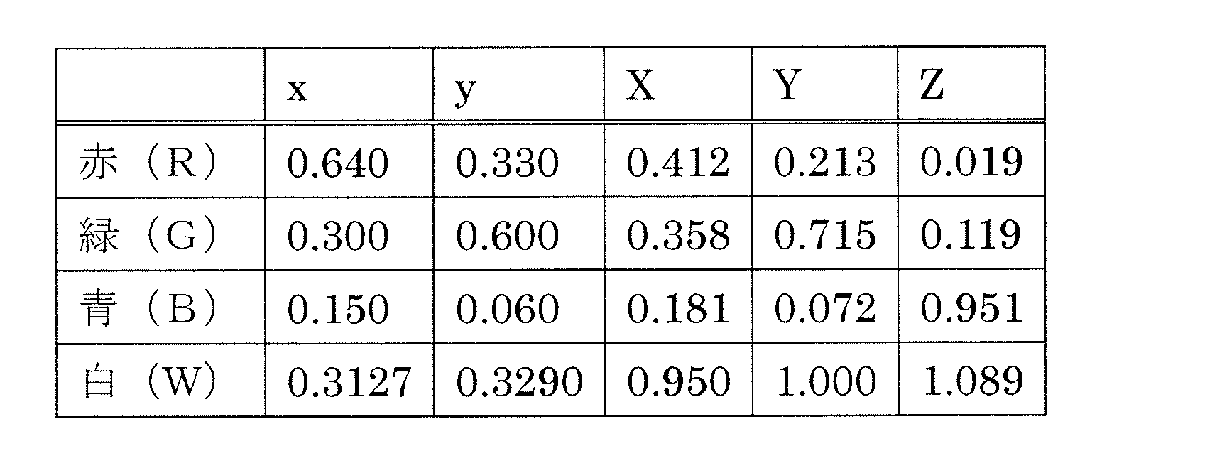
以下では、入力画像における一方の画素がダークスキンまたはライトスキンを示し、他方の画素が黒を示す場合を例示する。ここでいう「ダークスキン」および「ライトスキン」は、マクベスチャートにおけるダークスキンおよびライトスキンである。
下記表3に、三原色画像信号でダークスキンを表したときの赤、緑、青の階調および輝度(規格化輝度)を示し、下記表4に、ダークスキンの色度x、yおよび三刺激値X、Y、Zを示す。
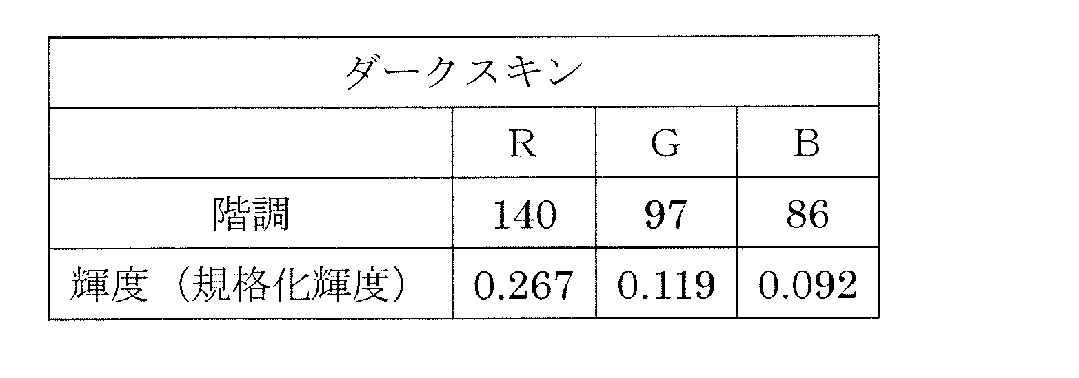

また、下記表5に、三原色画像信号でライトスキンを表したときの赤、緑、青の階調および輝度(規格化輝度)を示し、下記表6に、ライトスキンの色度x、yおよび三刺激値X、Y、Zを示す。
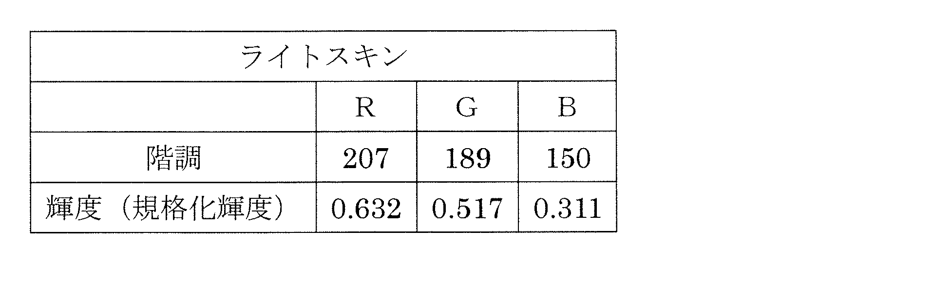

なお、ダークスキンおよびライトスキンの色度および三刺激値は、表4および表6に例示したものと厳密に同じでなくてもよく、例えば、ダークスキンおよびライトスキンの色度は、表4および表6に例示した値から0.02程度前後してもよく、ダークスキンおよびライトスキンのY値は、表4および表6に例示した値からそれぞれ0.005、0.01程度前後してもよい。
(実施形態1:ダークスキン)
表7に、ダークスキンを表示するための、赤サブ画素R、緑サブ画素G、青サブ画素B、黄サブ画素Yeの階調および輝度の組み合わせの例(♯1D~♯10D)を示す。表7には、輝度として、規格化輝度および絶対輝度の2種類の輝度を示している。規格化輝度は、各色の最高階調の輝度を1として規格化した輝度であり、絶対輝度は、規格化輝度に各色のY値を乗じたものである。また、表7には、各例について、赤サブ画素Rの絶対輝度および緑サブ画素Gの絶対輝度の和と、黄サブ画素Yeの絶対輝度との比(R+G:Ye)も併せて示されている。さらに、表8に、ダークスキンを正面方向から見たときの色度x、yおよびY値と、斜め60°方向から見たときの色度x、yおよびY値とを示す。また、表8には、ダークスキンを正面方向から見たときの色度を示す色度座標(u', v')と斜め60°方向から見たときの色度を示す色度座標(u60', v60')とによって規定される色差Δu'v'(=((u'-u60')2+(v'-v60')2)1/2)も併せて示されている。
表7に、ダークスキンを表示するための、赤サブ画素R、緑サブ画素G、青サブ画素B、黄サブ画素Yeの階調および輝度の組み合わせの例(♯1D~♯10D)を示す。表7には、輝度として、規格化輝度および絶対輝度の2種類の輝度を示している。規格化輝度は、各色の最高階調の輝度を1として規格化した輝度であり、絶対輝度は、規格化輝度に各色のY値を乗じたものである。また、表7には、各例について、赤サブ画素Rの絶対輝度および緑サブ画素Gの絶対輝度の和と、黄サブ画素Yeの絶対輝度との比(R+G:Ye)も併せて示されている。さらに、表8に、ダークスキンを正面方向から見たときの色度x、yおよびY値と、斜め60°方向から見たときの色度x、yおよびY値とを示す。また、表8には、ダークスキンを正面方向から見たときの色度を示す色度座標(u', v')と斜め60°方向から見たときの色度を示す色度座標(u60', v60')とによって規定される色差Δu'v'(=((u'-u60')2+(v'-v60')2)1/2)も併せて示されている。
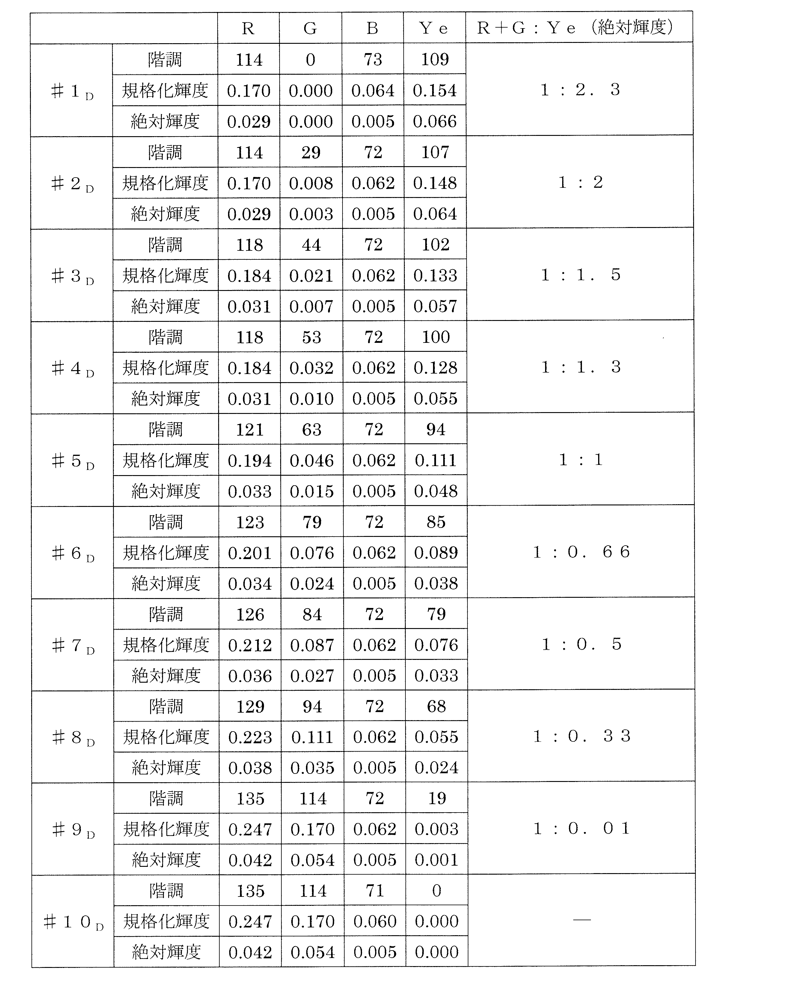
本実施形態の液晶表示装置100では、低域多原色信号生成部21は、入力画像における隣接した2画素のうちの一方の画素がダークスキンを示す場合、赤サブ画素Rの絶対輝度および緑サブ画素Gの絶対輝度の和に対する黄サブ画素Yeの絶対輝度の比が、0.5以上2.0以下になるように低域成分の多原色化を行う。つまり、表7に示されている組み合わせのうち、1番目および8番目~10番目の組み合わせ(♯1D、♯8D~♯10D)ではなく、2番目~7番目の組み合わせ(♯2D~♯7D)を選択するように多原色化を行う。
(実施形態2:ライトスキン)
表9に、ライトスキンを表示するための、赤サブ画素R、緑サブ画素G、青サブ画素B、黄サブ画素Yeの階調および輝度の組み合わせの例(♯1L~♯11L)を示す。表9には、輝度として、規格化輝度および絶対輝度の2種類の輝度を示している。また、表9には、各例について、赤サブ画素Rの絶対輝度および緑サブ画素Gの絶対輝度の和と、黄サブ画素Yeの絶対輝度との比(R+G:Ye)も併せて示されている。さらに、表10に、ライトスキンを正面方向から見たときの色度x、yおよびY値と、斜め60°方向から見たときの色度x、yおよびY値とを示す。また、表10には、ライトスキンを正面方向から見たときの色度を示す色度座標(u', v')と斜め60°方向から見たときの色度を示す色度座標(u60', v60')とによって規定される色差Δu'v'(=((u'-u60')2+(v'-v60')2)1/2)も併せて示されている。
表9に、ライトスキンを表示するための、赤サブ画素R、緑サブ画素G、青サブ画素B、黄サブ画素Yeの階調および輝度の組み合わせの例(♯1L~♯11L)を示す。表9には、輝度として、規格化輝度および絶対輝度の2種類の輝度を示している。また、表9には、各例について、赤サブ画素Rの絶対輝度および緑サブ画素Gの絶対輝度の和と、黄サブ画素Yeの絶対輝度との比(R+G:Ye)も併せて示されている。さらに、表10に、ライトスキンを正面方向から見たときの色度x、yおよびY値と、斜め60°方向から見たときの色度x、yおよびY値とを示す。また、表10には、ライトスキンを正面方向から見たときの色度を示す色度座標(u', v')と斜め60°方向から見たときの色度を示す色度座標(u60', v60')とによって規定される色差Δu'v'(=((u'-u60')2+(v'-v60')2)1/2)も併せて示されている。

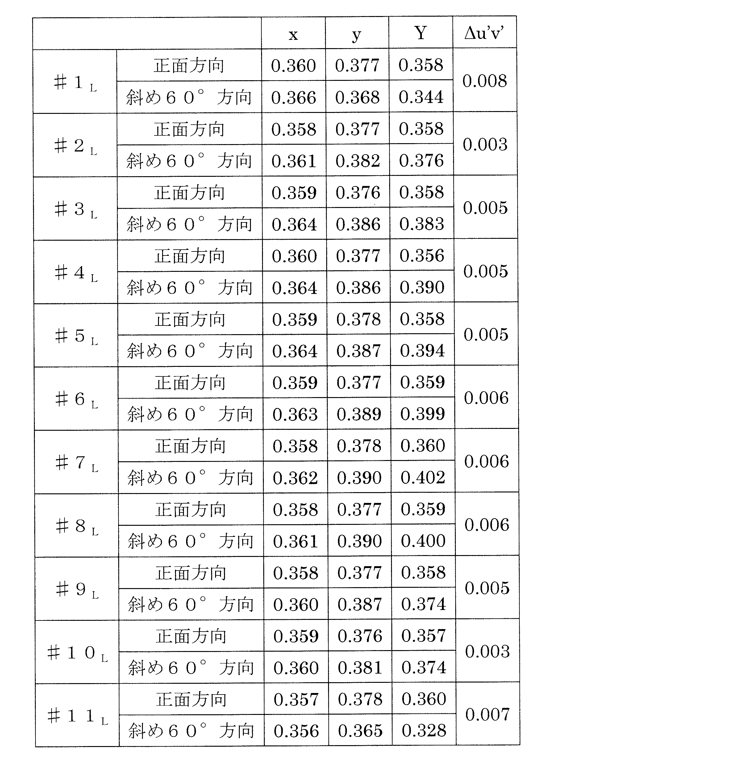
本実施形態の液晶表示装置100では、低域多原色信号生成部21は、入力画像における隣接した2画素のうちの一方の画素がライトスキンを示す場合、赤サブ画素Rの絶対輝度および緑サブ画素Gの絶対輝度の和に対する黄サブ画素Yeの絶対輝度の比が、0.5以上2.0以下になるように低域成分の多原色化を行う。つまり、表9に示されている組み合わせのうち、1番目、2番目、10番目および11番目の組み合わせ(♯1L、♯2L、♯10L、♯11L)ではなく、3番目~9番目の組み合わせ(♯3L~♯9L)を選択するように多原色化を行う。
上述したような多原色変換を行うことにより、輝度の逆転現象の発生を防止することができる。以下、このことを、表7中に示している5番目、7番目および2番目の組み合わせ(♯5D、♯7D、♯2D;以下ではそれぞれ実施例1、実施例2、実施例3と呼ぶ)を例としてより具体的な説明を行う。
図11は、入力画像において奇数列の画素が黒を示し、偶数列の画素がダークスキンを示している場合の多原色変換の例を示す図である。
この場合、入力画像信号では、図11(a)に示すように、奇数列の画素については、赤、緑、青の輝度(規格化輝度)がゼロであり、偶数列の画素については、赤、緑、青の輝度(規格化輝度)がゼロよりも大きい所定の値である。ここでは、偶数列の画素における赤、緑、青の輝度の最大値は0.123である。
まず、入力画像信号をLPFに通過させ、図11(b)に示すように、赤、緑、青の輝度が2つの画素で平均化された信号とする。この信号を多原色化(4色変換)する際、図11(c)に示すように、赤サブ画素Rの絶対輝度および緑サブ画素Gの絶対輝度の和に対する黄サブ画素Yeの絶対輝度の比が1になる組み合わせ(つまりR+G:Ye=1:1の組み合わせ)である実施例1(R=0.033、G=0.015、B=0.005、Ye=0.048)を選択し、多原色信号(低域多原色信号)を得る。
一方、入力画像信号から、図11(d)に示すように、赤、緑、青の輝度の最小値に対応する白成分(輝度信号に相当)を抽出する。ここでは、白成分の輝度(規格化輝度)は0.044(最大輝度の約1/3)である。次に、抽出された白成分を、HPFを通過させ、図11(e)に示すような奇数列に対応する分と、図11(f)に示すような偶数列に対応する分とに分離する。続いて、分離された白成分のそれぞれを、図11(g)および(h)に示すように、対応する仮想画素を構成するサブ画素の色の輝度に変換する。つまり、奇数列に対応する白成分は、奇数列に対応する仮想画素を構成するサブ画素の色(赤、緑、青)の輝度に変換し、偶数例に対応する白成分は、偶数列に対応する仮想画素を構成するサブ画素の色(青、黄、赤)の輝度に変換する。奇数列に対応する白成分はゼロであるため、図11(g)に示すように、変換後の各色の輝度もゼロである。これに対し、偶数列に対応する白成分はゼロではなく、図11(h)に示すように、変換後の青、黄、赤の輝度(絶対輝度)はそれぞれ0.024、0.042、0.003である。その後、図11(i)に示すように、これらを合算する。
合算後の輝度は、低域多原色信号とさらに合算される。ただし、この合算に際しては、入力画像信号から抽出された白成分をLPFに通過させたもの(図11(j)に示すように赤、緑、青、黄の絶対輝度に換算するとそれぞれ0.007、0.014、0.004、0.019)を低域多原色信号から減算し、減算後の輝度(図11(k)に示すように、ここでは赤、緑、青、黄がそれぞれ0.026、0.001、0.001、0.029)が、図11(i)に示す輝度と合算される。その結果、図11(l)に示すような多原色画像信号(R=0.026+(0.003)、G=0.001、B=0.025、Ye=0.071)が出力される。この多原色画像信号によれば、奇数列に対応する仮想画素および偶数列に対応する仮想画素の両方が点灯する。また、赤サブ画素Rの輝度と緑サブ画素の輝度との和(=0.027;隣接画素Pの赤サブ画素Rの輝度(=0.003)は除いている)よりも黄サブ画素Yeの輝度(=0.071)の方が高いことからわかるように、奇数列に対応する仮想画素の輝度よりも、偶数列に対応する仮想画素の輝度の方が高い。そのため、輝度の逆転現象が発生しない。
図12は、入力画像において奇数列の画素が黒を示し、偶数列の画素がダークスキンを示している場合の多原色変換の例を示す図である。
この場合、入力画像信号では、図12(a)に示すように、奇数列の画素については、赤、緑、青の輝度(規格化輝度)がゼロであり、偶数列の画素については、赤、緑、青の輝度(規格化輝度)がゼロよりも大きい所定の値である。ここでは、偶数列の画素における赤、緑、青の輝度の最大値は0.123である。
まず、入力画像信号をLPFに通過させ、図12(b)に示すように、赤、緑、青の輝度が2つの画素で平均化された信号とする。この信号を多原色化(4色変換)する際、図12(c)に示すように、赤サブ画素Rの絶対輝度および緑サブ画素Gの絶対輝度の和に対する黄サブ画素Yeの絶対輝度の比が0.5になる組み合わせ(つまりR+G:Ye=1:0.5の組み合わせ)である実施例2(R=0.036、G=0.027、B=0.005、Ye=0.033)を選択し、多原色信号(低域多原色信号)を得る。
一方、入力画像信号から、図12(d)に示すように、赤、緑、青の輝度の最小値に対応する白成分(輝度信号に相当)を抽出する。ここでは、白成分の輝度(規格化輝度)は0.044(最大輝度の約1/3)である。次に、抽出された白成分を、HPFを通過させ、図12(e)に示すような奇数列に対応する分と、図12(f)に示すような偶数列に対応する分とに分離する。続いて、分離された白成分のそれぞれを、図12(g)および(h)に示すように、対応する仮想画素を構成するサブ画素の色の輝度に変換する。つまり、奇数列に対応する白成分は、奇数列に対応する仮想画素を構成するサブ画素の色(赤、緑、青)の輝度に変換し、偶数例に対応する白成分は、偶数列に対応する仮想画素を構成するサブ画素の色(青、黄、赤)の輝度に変換する。奇数列に対応する白成分はゼロであるため、図12(g)に示すように、変換後の各色の輝度もゼロである。これに対し、偶数列に対応する白成分はゼロではなく、図12(h)に示すように、変換後の青、黄、赤の輝度(絶対輝度)はそれぞれ0.024、0.042、0.003である。その後、図12(i)に示すように、これらを合算する。
合算後の輝度は、低域多原色信号とさらに合算される。ただし、この合算に際しては、入力画像信号から抽出された白成分をLPFに通過させたもの(図12(j)に示すように赤、緑、青、黄の絶対輝度に換算するとそれぞれ0.007、0.014、0.004、0.019)を低域多原色信号から減算し、減算後の輝度(図12(k)に示すように、ここでは赤、緑、青、黄がそれぞれ0.029、0.013、0.001、0.014)が、図12(i)に示す輝度と合算される。その結果、図12(l)に示すような多原色画像信号(R=0.029+(0.003)、G=0.013、B=0.025、Ye=0.056)が出力される。この多原色画像信号によれば、奇数列に対応する仮想画素および偶数列に対応する仮想画素の両方が点灯する。また、赤サブ画素Rの輝度と緑サブ画素の輝度との和(=0.042)よりも黄サブ画素Yeの輝度(=0.056)の方が高いことからわかるように、奇数列に対応する仮想画素の輝度よりも、偶数列に対応する仮想画素の輝度の方が高い。そのため、輝度の逆転現象が発生しない。
図13は、入力画像において奇数列の画素がダークスキンを示し、偶数列の画素が黒を示している場合の多原色変換の例を示す図である。
この場合、入力画像信号では、図13(a)に示すように、奇数列の画素については、赤、緑、青の輝度(規格化輝度)がゼロよりも大きい所定の値であり、偶数列の画素については、赤、緑、青の輝度(規格化輝度)がゼロである。ここでは、奇数列の画素における赤、緑、青の輝度の最大値は0.123である。
まず、入力画像信号をLPFに通過させ、図13(b)に示すように、赤、緑、青の輝度が2つの画素で平均化された信号とする。この信号を多原色化(4色変換)する際、図13(c)に示すように、赤サブ画素Rの絶対輝度および緑サブ画素Gの絶対輝度の和に対する黄サブ画素Yeの絶対輝度の比が2になる組み合わせ(つまりR+G:Ye=1:2の組み合わせ)である実施例3(R=0.029、G=0.003、B=0.005、Ye=0.064)を選択し、多原色信号(低域多原色信号)を得る。
一方、入力画像信号から、図13(d)に示すように、赤、緑、青の輝度の最小値に対応する白成分(輝度信号に相当)を抽出する。ここでは、白成分の輝度(規格化輝度)は0.044(最大輝度の約1/3)である。次に、抽出された白成分を、HPFを通過させ、図13(e)に示すような奇数列に対応する分と、図13(f)に示すような偶数列に対応する分とに分離する。続いて、分離された白成分のそれぞれを、図13(g)および(h)に示すように、対応する仮想画素を構成するサブ画素の色の輝度に変換する。つまり、奇数列に対応する白成分は、奇数列に対応する仮想画素を構成するサブ画素の色(赤、緑、青)の輝度に変換し、偶数例に対応する白成分は、偶数列に対応する仮想画素を構成するサブ画素の色(青、黄、赤)の輝度に変換する。奇数列に対応する白成分はゼロではなく、図13(g)に示すように、変換後の赤、緑、青の輝度(絶対輝度)はそれぞれ0.012、0.032、0.003である。これに対し、偶数列に対応する白成分はゼロであるため、図13(h)に示すように、変換後の各色の輝度もゼロである。その後、図13(i)に示すように、これらを合算する。
合算後の輝度は、低域多原色信号とさらに合算される。ただし、この合算に際しては、入力画像信号から抽出された白成分をLPFに通過させたもの(図13(j)に示すように赤、緑、青、黄の絶対輝度に換算するとそれぞれ0.007、0.014、0.004、0.019)を低域多原色信号から減算し、減算後の輝度(図13(k)に示すように、ここでは赤、緑、青、黄がそれぞれ0.022、-0.011、0.001、0.045)が、図13(i)に示す輝度と合算される。その結果、図13(l)に示すような多原色画像信号(R=0.031、G=0.021、B=0.004、Ye=0.045)が出力される。この多原色画像信号によれば、奇数列に対応する仮想画素および偶数列に対応する仮想画素の両方が点灯する。また、赤サブ画素Rの輝度と緑サブ画素の輝度との和(=0.052)よりも黄サブ画素Yeの輝度(=0.045)の方が低いことからわかるように、奇数列に対応する仮想画素の輝度よりも、偶数列に対応する仮想画素の輝度の方が低い。そのため、輝度の逆転現象が発生しない。
上述したように、信号変換回路20の低域多原色信号生成部21が、実施例1、2または3の輝度の組み合わせを選択することにより、輝度の逆転現象の発生を防止することができる。
これに対し、例えば、表7における9番目の組み合わせ(♯9D;以下では比較例と呼ぶ)が選択された場合、輝度の逆転現象が発生してしまう。
図14は、入力画像において奇数列の画素が黒を示し、偶数列の画素がダークスキンを示している場合の多原色変換の例を示す図である。
この場合、入力画像信号では、図14(a)に示すように、奇数列の画素については、赤、緑、青の輝度(規格化輝度)がゼロであり、偶数列の画素については、赤、緑、青の輝度(規格化輝度)がゼロよりも大きい所定の値である。ここでは、偶数列の画素における赤、緑、青の輝度の最大値は0.123である。
まず、入力画像信号をLPFに通過させ、図14(b)に示すように、赤、緑、青の輝度が2つの画素で平均化された信号とする。この信号を多原色化(4色変換)する際、図14(c)に示すように、赤サブ画素Rの絶対輝度および緑サブ画素Gの絶対輝度の和に対する黄サブ画素Yeの絶対輝度の比が0.01になる組み合わせ(つまりR+G:Ye=1:0.01の組み合わせ)である比較例(R=0.042、G=0.054、B=0.005、Ye=0.001)を選択し、多原色信号(低域多原色信号)を得る。
一方、入力画像信号から、図14(d)に示すように、赤、緑、青の輝度の最小値に対応する白成分(輝度信号に相当)を抽出する。ここでは、白成分の輝度(規格化輝度)は0.044(最大輝度の約1/3)である。次に、抽出された白成分を、HPFを通過させ、図14(e)に示すような奇数列に対応する分と、図14(f)に示すような偶数列に対応する分とに分離する。続いて、分離された白成分のそれぞれを、図14(g)および(h)に示すように、対応する仮想画素を構成するサブ画素の色の輝度に変換する。つまり、奇数列に対応する白成分は、奇数列に対応する仮想画素を構成するサブ画素の色(赤、緑、青)の輝度に変換し、偶数例に対応する白成分は、偶数列に対応する仮想画素を構成するサブ画素の色(青、黄、赤)の輝度に変換する。奇数列に対応する白成分はゼロであるため、図14(g)に示すように、変換後の各色の輝度もゼロである。これに対し、偶数列に対応する白成分はゼロではなく、図14(h)に示すように、変換後の青、黄、赤の輝度(絶対輝度)はそれぞれ0.024、0.042、0.003である。その後、図14(i)に示すように、これらを合算する。
合算後の輝度は、低域多原色信号とさらに合算される。ただし、この合算に際しては、入力画像信号から抽出された白成分をLPFに通過させたもの(図14(j) に示すように赤、緑、青、黄の絶対輝度に換算するとそれぞれ0.007、0.014、0.004、0.019)を低域多原色信号から減算し、減算後の輝度(図14(k)に示すように、ここでは赤、緑、青、黄がそれぞれ0.035、0.040、0.001、-0.018)が、図14(i)に示す輝度と合算される。その結果、図14(l)に示すような多原色画像信号(R=0.035+(0.003)、G=0.040、B=0.025、Ye=0.024)が出力される。この多原色画像信号によれば、奇数列に対応する仮想画素および偶数列に対応する仮想画素の両方が点灯する。また、黄サブ画素Yeの輝度(=0.024)よりも赤サブ画素Rの輝度と緑サブ画素の輝度との和(=0.075)の方が高いことからわかるように、偶数列に対応する仮想画素の輝度よりも、奇数列に対応する仮想画素の輝度の方が高い。そのため、輝度の逆転現象が発生する。
上述したように、本実施形態の液晶表示装置100では、低域多原色信号生成部21が、入力画像における隣接した2画素のうちの一方の画素が特定の色を示す場合に、赤サブ画素Rの絶対輝度および緑サブ画素Gの絶対輝度の和に対する黄サブ画素Yeの絶対輝度の比が、0.5以上2.0以下になるように低域成分の多原色化を行うことにより、輝度の逆転現象の発生を防止することができる。
なお、赤サブ画素Rの絶対輝度および緑サブ画素Gの絶対輝度の和に対する黄サブ画素Yeの絶対輝度の比は、上記の範囲内(0.5以上2.0以下)であれば、特に限定されない。実施例1のように1(あるいは実質的に1)であってもよいし、実施例2のように0.5であってもよいし、実施例3のように2であってもよい。赤サブ画素Rの絶対輝度および緑サブ画素Gの絶対輝度の和に対する黄サブ画素Yeの絶対輝度の比が0.5以上2.0以下であれば、白成分が全体輝度の1/3以上の色について、輝度の逆転現象が発生しない。
ここで、図15を参照しながら、上記の範囲の下限値(0.5)および上限値(2.0)の意義を説明する。図15(a)~(l)は、入力画像において奇数列の画素が有彩色を示し、偶数列の画素が黒を示している場合の多原色変換の例を示す図であり、最も極端な例として、奇数列の画素における赤および緑の相対輝度(規格化輝度)が同じで、且つ、赤、緑および青の相対輝度の最大値に対して相対輝度の最少値が1/3である例を示している。相対輝度の最小値が最大値の1/3以下になると、白成分に対して色成分が2倍以上(1/3に対して2/3以上)となるので、2つの仮想画素に相対輝度が均等に分配されたときに、色成分が白成分を上回ることとなり、解像度向上の効果が得られにくくなってしまう。そのため、ここでは、相対輝度の最小値が最大値の1/3である例を示している。また、図15では、計算後に赤および緑の絶対輝度の和が最も大きくなるように、赤および緑の相対輝度が同じである例を示している。
ここでは、図15(a)に示すように、入力画像の奇数列における赤および緑の相対輝度を1としており、図15(d)に示すように、白成分を抽出するとその大きさ(相対輝度)は0.33となる。この白成分(相対輝度0.33)は、図15(j)に示すように、2画素に均等に振り分けられる。これは、白成分を相対輝度から絶対輝度に換算する際に、赤および緑と、黄とが、ほぼ半分ずつとなることを仮定している(図11および12からも、ほぼ半分になることがわかる)。
また、低域成分の多原色化の際には、図15(c)に示すように、赤および緑の絶対輝度の和に対する黄の絶対輝度の比が2.0となる組み合わせ(つまりR+G:Ye=1:2となる組み合わせ)を選択するので、それぞれの絶対輝度は、0.33、0.66となる。そして、図15(k)に示すように、これまでの例にならって、奇数列の画素については0.33から0.15を減算し、偶数列の画素については0.66から0.15を減算するので、減算後の赤および緑の絶対輝度の和は0.18、黄の絶対輝度は0.51となる。得られた値に対し、奇数列の画素について0.33(図15(i)参照)を加算すると、それぞれの絶対輝度が0.51、0.51となり、輝度の逆転現象がぎりぎり発生しないことがわかる。これに対し、低域成分の多原色化の際、仮に、赤の絶対輝度および緑の絶対輝度の和に対する黄の絶対輝度の比が2.0を超える組み合わせを選択すると、輝度の逆転現象が発生してしまう。そのため、赤サブ画素Rの絶対輝度および緑サブ画素Gの絶対輝度の和に対する黄サブ画素Yeの絶対輝度の比は、2.0以下であることが好ましい。同様の理由から、赤の絶対輝度および緑の絶対輝度の和に対する黄の絶対輝度の比が0.5未満であると、輝度の逆転現象が発生してしまうので、赤サブ画素Rの絶対輝度および緑サブ画素Gの絶対輝度の和に対する黄サブ画素Yeの絶対輝度の比は、0.5以上であることが好ましい。
なお、上記の説明では、入力画像における隣接した2画素のうちの一方の画素が示す特定の色がダークスキンまたはライトスキンである場合を例示したが、勿論、本発明の実施形態はこれに限定されるものではない。上記特定の色は、典型的には、有彩色であり、且つ、青の規格化輝度が、赤の規格化輝度および緑の規格化輝度のうちの大きい方の1/3よりも大きい色(つまりB>MAX(R,G)/3の色)である。表3からわかるように、ダークスキンは、青の規格化輝度が、赤の規格化輝度および緑の規格化輝度のうちの大きい方の1/3よりも大きい色である(0.092>0.267/3である)。また、表5からわかるように、ライトスキンも、青の規格化輝度が、赤の規格化輝度および緑の規格化輝度のうちの大きい方の1/3よりも大きい色である(0.311>0.632/3)。
また、上記の説明では、入力画像における隣接した2画素のうちの他方の画素が示す色が黒である場合を例示したが、本発明の実施形態はこれに限定されるものではない。他方の画素が示す色は、上記特定の色であってもよい。つまり、入力画像は、上記特定の色のべた画像であってもよい。
なお、高い視野角特性を実現する観点からは、低域多原色信号生成部21は、入力画像における一方の画素が特定の色を示す場合、低域多原色信号によって表わされる色を正面方向から見たときの色度を示す色度座標(u', v')と斜め60°方向から見たときの色度を示す色度座標(u60', v60')とによって規定される色差Δu'v'(=((u'-u60')2+(v'-v60')2)1/2が0.03以下となるように多原色化を行うことが好ましい。表7および表8の2番目~6番目の組み合わせ(♯2D~♯6D)や、表9および表10の3番目~9番目の組み合わせ(♯3L~♯9L)は、この条件を満足している。
また、同様の観点から、低域多原色信号生成部21は、入力画像における一方の画素がダークスキンを示す場合、低域多原色信号によって表わされる色を正面方向から見たときの色度を示す色度座標(u', v')と斜め60°方向から見たときの色度を示す色度座標(u60', v60')とによって規定される色差Δu'v'が0.03以下となるように多原色化を行うことが好ましい。表7および表8の2番目~6番目の組み合わせ(♯2D~♯6D)は、この条件を満足している。
また、同様の観点から、低域多原色信号生成部21は、入力画像における一方の画素がライトスキンを示す場合、低域多原色信号によって表わされる色を正面方向から見たときの色度を示す色度座標(u', v')と斜め60°方向から見たときの色度を示す色度座標(u60', v60')とによって規定される色差Δu'v'が0.01以下となるように多原色化を行うことが好ましい。表9および表10の3番目~9番目の組み合わせ(♯3L~♯9L)は、この条件を満足している。
なお、各サブ画素の絶対輝度は、例えば、Radiant Zemax社製のイメージング色彩輝度計ProMetric Iによって測定することができる。
本発明の実施形態による多原色表示装置は、高品位の表示を行うことができるので、種々の電子機器に用いられ、例えば、テレビジョン受像機に好適に用いられる。テレビジョン受像機は、多原色表示装置に加えて、テレビジョン放送を受信する回路を備える。
上記の説明からわかるように、本発明の実施形態による多原色表示装置の駆動方法は、3原色に対応した入力画像信号を4つの原色(赤、緑、青および黄)に対応した多原色画像信号に変換するステップ(A)と、赤サブ画素R、緑サブ画素G、青サブ画素Bおよび黄サブ画素Yeを2つの仮想画素VP1およびVP2に振り分け、入力画像における隣接した2画素分の表示を2つの仮想画素VP1およびVP2によって行うステップ(B)とを包含する。
ステップ(A)(信号変換ステップ)は、入力画像信号に基づいて低域多原色信号を生成するステップ(a)(低域多原色信号生成ステップ)と、入力画像信号に基づいて高域輝度信号を生成するステップ(b)(高域輝度信号生成ステップ)と、低域多原色信号および高域輝度信号に基づいて2つの仮想画素VP1およびVP2へのレンダリング処理を行うステップ(c)(レンダリング処理ステップ)とを含む。
ステップ(a)において、入力画像における隣接した2画素のうちの一方の画素が特定の色を示す場合、赤サブ画素Rの絶対輝度および緑サブ画素Gの絶対輝度の和に対する黄サブ画素Yeの絶対輝度の比が、0.5以上2.0以下になるように低域成分の多原色化が行われる。あるいは、ステップ(a)において、入力画像における隣接した2画素の輝度の大小関係と、それら2画素に対応する2つの仮想画素の輝度の大小関係とが反対にならないように低域成分の多原色化が行われる、ともいえる。
本明細書は、以下の項目に記載の多原色表示装置を開示している。
[項目1]
赤サブ画素、緑サブ画素、青サブ画素および黄サブ画素から構成される画素を有し、赤、緑、青および黄の4つの原色を用いてカラー表示を行う多原色表示装置であって、
各画素に前記赤サブ画素、前記緑サブ画素、前記青サブ画素および前記黄サブ画素を有する多原色表示パネルと、
3原色に対応した入力画像信号を前記4つの原色に対応した多原色画像信号に変換する信号変換回路と、を備え、
前記画素を構成する前記赤サブ画素、前記緑サブ画素、前記青サブ画素および前記黄サブ画素を2つの仮想画素に振り分け、入力画像における隣接した2画素分の表示を前記2つの仮想画素によって行うことができ、
前記信号変換回路は、
前記入力画像信号に基づいて、前記入力画像信号の低域成分が多原色化された信号である低域多原色信号を生成する低域多原色信号生成部と、
前記入力画像信号に基づいて、前記入力画像信号の高域成分が輝度変換された信号である高域輝度信号を生成する高域輝度信号生成部と、
前記低域多原色信号および前記高域輝度信号に基づいて、前記2つの仮想画素へのレンダリング処理を行うレンダリング処理部と、を有し、
前記低域多原色信号生成部は、前記入力画像における前記隣接した2画素のうちの一方の画素が特定の色を示す場合、前記赤サブ画素の絶対輝度および前記緑サブ画素の絶対輝度の和に対する前記黄サブ画素の絶対輝度の比が、0.5以上2.0以下になるように前記低域成分の多原色化を行い得る多原色表示装置。
赤サブ画素、緑サブ画素、青サブ画素および黄サブ画素から構成される画素を有し、赤、緑、青および黄の4つの原色を用いてカラー表示を行う多原色表示装置であって、
各画素に前記赤サブ画素、前記緑サブ画素、前記青サブ画素および前記黄サブ画素を有する多原色表示パネルと、
3原色に対応した入力画像信号を前記4つの原色に対応した多原色画像信号に変換する信号変換回路と、を備え、
前記画素を構成する前記赤サブ画素、前記緑サブ画素、前記青サブ画素および前記黄サブ画素を2つの仮想画素に振り分け、入力画像における隣接した2画素分の表示を前記2つの仮想画素によって行うことができ、
前記信号変換回路は、
前記入力画像信号に基づいて、前記入力画像信号の低域成分が多原色化された信号である低域多原色信号を生成する低域多原色信号生成部と、
前記入力画像信号に基づいて、前記入力画像信号の高域成分が輝度変換された信号である高域輝度信号を生成する高域輝度信号生成部と、
前記低域多原色信号および前記高域輝度信号に基づいて、前記2つの仮想画素へのレンダリング処理を行うレンダリング処理部と、を有し、
前記低域多原色信号生成部は、前記入力画像における前記隣接した2画素のうちの一方の画素が特定の色を示す場合、前記赤サブ画素の絶対輝度および前記緑サブ画素の絶対輝度の和に対する前記黄サブ画素の絶対輝度の比が、0.5以上2.0以下になるように前記低域成分の多原色化を行い得る多原色表示装置。
[項目2]
前記特定の色は、有彩色であり、且つ、青の規格化輝度が、赤の規格化輝度および緑の規格化輝度のうちの大きい方の1/3よりも大きい色である項目1に記載の多原色表示装置。
前記特定の色は、有彩色であり、且つ、青の規格化輝度が、赤の規格化輝度および緑の規格化輝度のうちの大きい方の1/3よりも大きい色である項目1に記載の多原色表示装置。
[項目3]
前記低域多原色信号生成部は、前記入力画像における前記一方の画素が前記特定の色を示す場合、前記赤サブ画素の絶対輝度および前記緑サブ画素の絶対輝度の和に対する前記黄サブ画素の絶対輝度の比が、実質的に1になるように多原色化を行い得る項目1または2に記載の多原色表示装置。
前記低域多原色信号生成部は、前記入力画像における前記一方の画素が前記特定の色を示す場合、前記赤サブ画素の絶対輝度および前記緑サブ画素の絶対輝度の和に対する前記黄サブ画素の絶対輝度の比が、実質的に1になるように多原色化を行い得る項目1または2に記載の多原色表示装置。
[項目4]
前記低域多原色信号生成部は、前記入力画像における前記一方の画素が前記特定の色を示す場合、前記低域多原色信号によって表わされる色を正面方向から見たときの色度を示す色度座標(u', v')と斜め60°方向から見たときの色度を示す色度座標(u60', v60')とによって規定される色差Δu'v'=((u'-u60')2+(v'-v60')2)1/2が0.03以下となるように多原色化を行い得る、項目1から3のいずれかに記載の多原色表示装置。
前記低域多原色信号生成部は、前記入力画像における前記一方の画素が前記特定の色を示す場合、前記低域多原色信号によって表わされる色を正面方向から見たときの色度を示す色度座標(u', v')と斜め60°方向から見たときの色度を示す色度座標(u60', v60')とによって規定される色差Δu'v'=((u'-u60')2+(v'-v60')2)1/2が0.03以下となるように多原色化を行い得る、項目1から3のいずれかに記載の多原色表示装置。
[項目5]
前記特定の色はダークスキンであり、
前記低域多原色信号生成部は、前記入力画像における前記一方の画素がダークスキンを示す場合、前記低域多原色信号によって表わされる色を正面方向から見たときの色度を示す色度座標(u', v')と斜め60°方向から見たときの色度を示す色度座標(u60', v60')とによって規定される色差Δu'v'=((u'-u60')2+(v'-v60')2)1/2が0.03以下となるように多原色化を行い得る項目1から4のいずれかに記載の多原色表示装置。
前記特定の色はダークスキンであり、
前記低域多原色信号生成部は、前記入力画像における前記一方の画素がダークスキンを示す場合、前記低域多原色信号によって表わされる色を正面方向から見たときの色度を示す色度座標(u', v')と斜め60°方向から見たときの色度を示す色度座標(u60', v60')とによって規定される色差Δu'v'=((u'-u60')2+(v'-v60')2)1/2が0.03以下となるように多原色化を行い得る項目1から4のいずれかに記載の多原色表示装置。
[項目6]
前記特定の色はライトスキンであり、
前記低域多原色信号生成部は、前記入力画像における前記一方の画素がライトスキンを示す場合、前記低域多原色信号によって表わされる色を正面方向から見たときの色度を示す色度座標(u', v')と斜め60°方向から見たときの色度を示す色度座標(u60', v60')とによって規定される色差Δu'v'=((u'-u60')2+(v'-v60')2)1/2が0.01以下となるように多原色化を行い得る項目1から5のいずれかに記載の多原色表示装置。
前記特定の色はライトスキンであり、
前記低域多原色信号生成部は、前記入力画像における前記一方の画素がライトスキンを示す場合、前記低域多原色信号によって表わされる色を正面方向から見たときの色度を示す色度座標(u', v')と斜め60°方向から見たときの色度を示す色度座標(u60', v60')とによって規定される色差Δu'v'=((u'-u60')2+(v'-v60')2)1/2が0.01以下となるように多原色化を行い得る項目1から5のいずれかに記載の多原色表示装置。
[項目7]
前記入力画像における前記隣接した2画素のうちの前記一方の画素が特定の色を示す場合、他方の画素は黒を示している項目1から6のいずれかに記載の多原色表示装置。
前記入力画像における前記隣接した2画素のうちの前記一方の画素が特定の色を示す場合、他方の画素は黒を示している項目1から6のいずれかに記載の多原色表示装置。
[項目8]
前記2つの仮想画素のそれぞれは、前記赤サブ画素、前記緑サブ画素、前記青サブ画素および前記黄サブ画素のうちの2つ以上のサブ画素によって構成される項目1から7のいずれかに記載の多原色表示装置。
前記2つの仮想画素のそれぞれは、前記赤サブ画素、前記緑サブ画素、前記青サブ画素および前記黄サブ画素のうちの2つ以上のサブ画素によって構成される項目1から7のいずれかに記載の多原色表示装置。
[項目9]
前記画素は、複数の行および複数の列を含むマトリクス状に複数配置されており、
前記複数の画素のそれぞれ内で、前記赤サブ画素、前記緑サブ画素、前記青サブ画素および前記黄サブ画素は1行4列に配列されている項目1から8のいずれかに記載の多原色表示装置。
前記画素は、複数の行および複数の列を含むマトリクス状に複数配置されており、
前記複数の画素のそれぞれ内で、前記赤サブ画素、前記緑サブ画素、前記青サブ画素および前記黄サブ画素は1行4列に配列されている項目1から8のいずれかに記載の多原色表示装置。
[項目10]
液晶表示装置である項目1から9のいずれかに記載の多原色表示装置。
液晶表示装置である項目1から9のいずれかに記載の多原色表示装置。
[項目11]
赤サブ画素、緑サブ画素、青サブ画素および黄サブ画素から構成される画素を有し、赤、緑、青および黄の4つの原色を用いてカラー表示を行う多原色表示装置であって、
各画素に前記赤サブ画素、前記緑サブ画素、前記青サブ画素および前記黄サブ画素を有する多原色表示パネルと、
3原色に対応した入力画像信号を前記4つの原色に対応した多原色画像信号に変換する信号変換回路と、を備え、
前記画素を構成する前記赤サブ画素、前記緑サブ画素、前記青サブ画素および前記黄サブ画素を2つの仮想画素に振り分け、入力画像における隣接した2画素分の表示を前記2つの仮想画素によって行うことができ、
前記信号変換回路は、
前記入力画像信号に基づいて、前記入力画像信号の低域成分が多原色化された信号である低域多原色信号を生成する低域多原色信号生成部と、
前記入力画像信号に基づいて、前記入力画像信号の高域成分が輝度変換された信号である高域輝度信号を生成する高域輝度信号生成部と、
前記低域多原色信号および前記高域輝度信号に基づいて、前記2つの仮想画素へのレンダリング処理を行うレンダリング処理部と、を有し、
前記低域多原色信号生成部は、前記入力画像における前記隣接した2画素のうちの一方の画素および他方の画素の輝度の大小関係と、前記一方の画素に対応する仮想画素および前記他方の画素に対応する仮想画素の輝度の大小関係とが反対にならないように前記低域成分の多原色化を行い得る多原色表示装置。
赤サブ画素、緑サブ画素、青サブ画素および黄サブ画素から構成される画素を有し、赤、緑、青および黄の4つの原色を用いてカラー表示を行う多原色表示装置であって、
各画素に前記赤サブ画素、前記緑サブ画素、前記青サブ画素および前記黄サブ画素を有する多原色表示パネルと、
3原色に対応した入力画像信号を前記4つの原色に対応した多原色画像信号に変換する信号変換回路と、を備え、
前記画素を構成する前記赤サブ画素、前記緑サブ画素、前記青サブ画素および前記黄サブ画素を2つの仮想画素に振り分け、入力画像における隣接した2画素分の表示を前記2つの仮想画素によって行うことができ、
前記信号変換回路は、
前記入力画像信号に基づいて、前記入力画像信号の低域成分が多原色化された信号である低域多原色信号を生成する低域多原色信号生成部と、
前記入力画像信号に基づいて、前記入力画像信号の高域成分が輝度変換された信号である高域輝度信号を生成する高域輝度信号生成部と、
前記低域多原色信号および前記高域輝度信号に基づいて、前記2つの仮想画素へのレンダリング処理を行うレンダリング処理部と、を有し、
前記低域多原色信号生成部は、前記入力画像における前記隣接した2画素のうちの一方の画素および他方の画素の輝度の大小関係と、前記一方の画素に対応する仮想画素および前記他方の画素に対応する仮想画素の輝度の大小関係とが反対にならないように前記低域成分の多原色化を行い得る多原色表示装置。
[項目12]
項目1から11のいずれかに記載の多原色表示装置を備えたテレビジョン受像機。
項目1から11のいずれかに記載の多原色表示装置を備えたテレビジョン受像機。
[項目13]
赤サブ画素、緑サブ画素、青サブ画素および黄サブ画素から構成される画素を有し、赤、緑、青および黄の4つの原色を用いてカラー表示を行う多原色表示装置の駆動方法であって、
3原色に対応した入力画像信号を前記4つの原色に対応した多原色画像信号に変換するステップ(A)と、
前記画素を構成する前記赤サブ画素、前記緑サブ画素、前記青サブ画素および前記黄サブ画素を2つの仮想画素に振り分け、入力画像における隣接した2画素分の表示を前記2つの仮想画素によって行うステップ(B)と、を包含し、
前記ステップ(A)は、
前記入力画像信号に基づいて、前記入力画像信号の低域成分が多原色化された信号である低域多原色信号を生成するステップ(a)と、
前記入力画像信号に基づいて、前記入力画像信号の高域成分が輝度変換された信号である高域輝度信号を生成するステップ(b)と、
前記低域多原色信号および前記高域輝度信号に基づいて、前記2つの仮想画素へのレンダリング処理を行うステップ(c)と、を含み、
前記ステップ(a)において、前記入力画像における前記隣接した2画素のうちの一方の画素が特定の色を示す場合、前記赤サブ画素の絶対輝度および前記緑サブ画素の絶対輝度の和に対する前記黄サブ画素の絶対輝度の比が、0.5以上2.0以下になるように前記低域成分の多原色化が行われる多原色表示装置の駆動方法。
赤サブ画素、緑サブ画素、青サブ画素および黄サブ画素から構成される画素を有し、赤、緑、青および黄の4つの原色を用いてカラー表示を行う多原色表示装置の駆動方法であって、
3原色に対応した入力画像信号を前記4つの原色に対応した多原色画像信号に変換するステップ(A)と、
前記画素を構成する前記赤サブ画素、前記緑サブ画素、前記青サブ画素および前記黄サブ画素を2つの仮想画素に振り分け、入力画像における隣接した2画素分の表示を前記2つの仮想画素によって行うステップ(B)と、を包含し、
前記ステップ(A)は、
前記入力画像信号に基づいて、前記入力画像信号の低域成分が多原色化された信号である低域多原色信号を生成するステップ(a)と、
前記入力画像信号に基づいて、前記入力画像信号の高域成分が輝度変換された信号である高域輝度信号を生成するステップ(b)と、
前記低域多原色信号および前記高域輝度信号に基づいて、前記2つの仮想画素へのレンダリング処理を行うステップ(c)と、を含み、
前記ステップ(a)において、前記入力画像における前記隣接した2画素のうちの一方の画素が特定の色を示す場合、前記赤サブ画素の絶対輝度および前記緑サブ画素の絶対輝度の和に対する前記黄サブ画素の絶対輝度の比が、0.5以上2.0以下になるように前記低域成分の多原色化が行われる多原色表示装置の駆動方法。
[項目14]
赤サブ画素、緑サブ画素、青サブ画素および黄サブ画素から構成される画素を有し、赤、緑、青および黄の4つの原色を用いてカラー表示を行う多原色表示装置であって、
3原色に対応した入力画像信号を前記4つの原色に対応した多原色画像信号に変換するステップ(A)と、
前記画素を構成する前記赤サブ画素、前記緑サブ画素、前記青サブ画素および前記黄サブ画素を2つの仮想画素に振り分け、入力画像における隣接した2画素分の表示を前記2つの仮想画素によって行うステップ(B)と、を包含し、
前記ステップ(A)は、
前記入力画像信号に基づいて、前記入力画像信号の低域成分が多原色化された信号である低域多原色信号を生成するステップ(a)と、
前記入力画像信号に基づいて、前記入力画像信号の高域成分が輝度変換された信号である高域輝度信号を生成するステップ(b)と、
前記低域多原色信号および前記高域輝度信号に基づいて、前記2つの仮想画素へのレンダリング処理を行うステップ(c)と、を含み、
前記ステップ(a)において、前記入力画像における前記隣接した2画素のうちの一方の画素および他方の画素の輝度の大小関係と、前記一方の画素に対応する仮想画素および前記他方の画素に対応する仮想画素の輝度の大小関係とが反対にならないように前記低域成分の多原色化が行われる多原色表示装置の駆動方法。
赤サブ画素、緑サブ画素、青サブ画素および黄サブ画素から構成される画素を有し、赤、緑、青および黄の4つの原色を用いてカラー表示を行う多原色表示装置であって、
3原色に対応した入力画像信号を前記4つの原色に対応した多原色画像信号に変換するステップ(A)と、
前記画素を構成する前記赤サブ画素、前記緑サブ画素、前記青サブ画素および前記黄サブ画素を2つの仮想画素に振り分け、入力画像における隣接した2画素分の表示を前記2つの仮想画素によって行うステップ(B)と、を包含し、
前記ステップ(A)は、
前記入力画像信号に基づいて、前記入力画像信号の低域成分が多原色化された信号である低域多原色信号を生成するステップ(a)と、
前記入力画像信号に基づいて、前記入力画像信号の高域成分が輝度変換された信号である高域輝度信号を生成するステップ(b)と、
前記低域多原色信号および前記高域輝度信号に基づいて、前記2つの仮想画素へのレンダリング処理を行うステップ(c)と、を含み、
前記ステップ(a)において、前記入力画像における前記隣接した2画素のうちの一方の画素および他方の画素の輝度の大小関係と、前記一方の画素に対応する仮想画素および前記他方の画素に対応する仮想画素の輝度の大小関係とが反対にならないように前記低域成分の多原色化が行われる多原色表示装置の駆動方法。
本発明の実施形態によると、仮想画素を用いた表示により解像度を向上させることができる多原色表示装置において、入力側と出力側とでの輝度の逆転現象の発生を防止することができる。
本発明の実施形態による多原色表示装置は、高品位の表示を行うことができるので、液晶テレビをはじめとする種々の電子機器に好適に用いられる。
10 多原色表示パネル
20 信号変換回路
21 低域多原色信号生成部
22 高域輝度信号生成部
23 レンダリング処理部
24 γ補正部
25 逆γ補正部
26 低域成分抽出部(ローパスフィルタ)
27 多原色変換部
28 輝度変換部
29 高域成分抽出部(ハイパスフィルタ)
100 液晶表示装置(多原色表示装置)
P 画素
R 赤サブ画素
G 緑サブ画素
B 青サブ画素
Ye 黄サブ画素
VP1 第1仮想画素
VP2 第2仮想画素
20 信号変換回路
21 低域多原色信号生成部
22 高域輝度信号生成部
23 レンダリング処理部
24 γ補正部
25 逆γ補正部
26 低域成分抽出部(ローパスフィルタ)
27 多原色変換部
28 輝度変換部
29 高域成分抽出部(ハイパスフィルタ)
100 液晶表示装置(多原色表示装置)
P 画素
R 赤サブ画素
G 緑サブ画素
B 青サブ画素
Ye 黄サブ画素
VP1 第1仮想画素
VP2 第2仮想画素
Claims (14)
- 赤サブ画素、緑サブ画素、青サブ画素および黄サブ画素から構成される画素を有し、赤、緑、青および黄の4つの原色を用いてカラー表示を行う多原色表示装置であって、
各画素に前記赤サブ画素、前記緑サブ画素、前記青サブ画素および前記黄サブ画素を有する多原色表示パネルと、
3原色に対応した入力画像信号を前記4つの原色に対応した多原色画像信号に変換する信号変換回路と、を備え、
前記画素を構成する前記赤サブ画素、前記緑サブ画素、前記青サブ画素および前記黄サブ画素を2つの仮想画素に振り分け、入力画像における隣接した2画素分の表示を前記2つの仮想画素によって行うことができ、
前記信号変換回路は、
前記入力画像信号に基づいて、前記入力画像信号の低域成分が多原色化された信号である低域多原色信号を生成する低域多原色信号生成部と、
前記入力画像信号に基づいて、前記入力画像信号の高域成分が輝度変換された信号である高域輝度信号を生成する高域輝度信号生成部と、
前記低域多原色信号および前記高域輝度信号に基づいて、前記2つの仮想画素へのレンダリング処理を行うレンダリング処理部と、を有し、
前記低域多原色信号生成部は、前記入力画像における前記隣接した2画素のうちの一方の画素が特定の色を示す場合、前記赤サブ画素の絶対輝度および前記緑サブ画素の絶対輝度の和に対する前記黄サブ画素の絶対輝度の比が、0.5以上2.0以下になるように前記低域成分の多原色化を行い得る多原色表示装置。 - 前記特定の色は、有彩色であり、且つ、青の規格化輝度が、赤の規格化輝度および緑の規格化輝度のうちの大きい方の1/3よりも大きい色である請求項1に記載の多原色表示装置。
- 前記低域多原色信号生成部は、前記入力画像における前記一方の画素が前記特定の色を示す場合、前記赤サブ画素の絶対輝度および前記緑サブ画素の絶対輝度の和に対する前記黄サブ画素の絶対輝度の比が、実質的に1になるように多原色化を行い得る請求項1または2に記載の多原色表示装置。
- 前記低域多原色信号生成部は、前記入力画像における前記一方の画素が前記特定の色を示す場合、前記低域多原色信号によって表わされる色を正面方向から見たときの色度を示す色度座標(u', v')と斜め60°方向から見たときの色度を示す色度座標(u60', v60')とによって規定される色差Δu'v'=((u'-u60')2+(v'-v60')2)1/2が0.03以下となるように多原色化を行い得る請求項1から3のいずれかに記載の多原色表示装置。
- 前記特定の色はダークスキンであり、
前記低域多原色信号生成部は、前記入力画像における前記一方の画素がダークスキンを示す場合、前記低域多原色信号によって表わされる色を正面方向から見たときの色度を示す色度座標(u', v')と斜め60°方向から見たときの色度を示す色度座標(u60', v60')とによって規定される色差Δu'v'=((u'-u60')2+(v'-v60')2)1/2が0.03以下となるように多原色化を行い得る請求項1から4のいずれかに記載の多原色表示装置。 - 前記特定の色はライトスキンであり、
前記低域多原色信号生成部は、前記入力画像における前記一方の画素がライトスキンを示す場合、前記低域多原色信号によって表わされる色を正面方向から見たときの色度を示す色度座標(u', v')と斜め60°方向から見たときの色度を示す色度座標(u60', v60')とによって規定される色差Δu'v'=((u'-u60')2+(v'-v60')2)1/2が0.01以下となるように多原色化を行い得る請求項1から5のいずれかに記載の多原色表示装置。 - 前記入力画像における前記隣接した2画素のうちの前記一方の画素が特定の色を示す場合、他方の画素は黒を示している請求項1から6のいずれかに記載の多原色表示装置。
- 前記2つの仮想画素のそれぞれは、前記赤サブ画素、前記緑サブ画素、前記青サブ画素および前記黄サブ画素のうちの2つ以上のサブ画素によって構成される請求項1から7のいずれかに記載の多原色表示装置。
- 前記画素は、複数の行および複数の列を含むマトリクス状に複数配置されており、
前記複数の画素のそれぞれ内で、前記赤サブ画素、前記緑サブ画素、前記青サブ画素および前記黄サブ画素は1行4列に配列されている請求項1から8のいずれかに記載の多原色表示装置。 - 液晶表示装置である請求項1から9のいずれかに記載の多原色表示装置。
- 赤サブ画素、緑サブ画素、青サブ画素および黄サブ画素から構成される画素を有し、赤、緑、青および黄の4つの原色を用いてカラー表示を行う多原色表示装置であって、
各画素に前記赤サブ画素、前記緑サブ画素、前記青サブ画素および前記黄サブ画素を有する多原色表示パネルと、
3原色に対応した入力画像信号を前記4つの原色に対応した多原色画像信号に変換する信号変換回路と、を備え、
前記画素を構成する前記赤サブ画素、前記緑サブ画素、前記青サブ画素および前記黄サブ画素を2つの仮想画素に振り分け、入力画像における隣接した2画素分の表示を前記2つの仮想画素によって行うことができ、
前記信号変換回路は、
前記入力画像信号に基づいて、前記入力画像信号の低域成分が多原色化された信号である低域多原色信号を生成する低域多原色信号生成部と、
前記入力画像信号に基づいて、前記入力画像信号の高域成分が輝度変換された信号である高域輝度信号を生成する高域輝度信号生成部と、
前記低域多原色信号および前記高域輝度信号に基づいて、前記2つの仮想画素へのレンダリング処理を行うレンダリング処理部と、を有し、
前記低域多原色信号生成部は、前記入力画像における前記隣接した2画素のうちの一方の画素および他方の画素の輝度の大小関係と、前記一方の画素に対応する仮想画素および前記他方の画素に対応する仮想画素の輝度の大小関係とが反対にならないように前記低域成分の多原色化を行い得る多原色表示装置。 - 請求項1から11のいずれかに記載の多原色表示装置を備えたテレビジョン受像機。
- 赤サブ画素、緑サブ画素、青サブ画素および黄サブ画素から構成される画素を有し、赤、緑、青および黄の4つの原色を用いてカラー表示を行う多原色表示装置の駆動方法であって、
3原色に対応した入力画像信号を前記4つの原色に対応した多原色画像信号に変換するステップ(A)と、
前記画素を構成する前記赤サブ画素、前記緑サブ画素、前記青サブ画素および前記黄サブ画素を2つの仮想画素に振り分け、入力画像における隣接した2画素分の表示を前記2つの仮想画素によって行うステップ(B)と、を包含し、
前記ステップ(A)は、
前記入力画像信号に基づいて、前記入力画像信号の低域成分が多原色化された信号である低域多原色信号を生成するステップ(a)と、
前記入力画像信号に基づいて、前記入力画像信号の高域成分が輝度変換された信号である高域輝度信号を生成するステップ(b)と、
前記低域多原色信号および前記高域輝度信号に基づいて、前記2つの仮想画素へのレンダリング処理を行うステップ(c)と、を含み、
前記ステップ(a)において、前記入力画像における前記隣接した2画素のうちの一方の画素が特定の色を示す場合、前記赤サブ画素の絶対輝度および前記緑サブ画素の絶対輝度の和に対する前記黄サブ画素の絶対輝度の比が、0.5以上2.0以下になるように前記低域成分の多原色化が行われる多原色表示装置の駆動方法。 - 赤サブ画素、緑サブ画素、青サブ画素および黄サブ画素から構成される画素を有し、赤、緑、青および黄の4つの原色を用いてカラー表示を行う多原色表示装置であって、
3原色に対応した入力画像信号を前記4つの原色に対応した多原色画像信号に変換するステップ(A)と、
前記画素を構成する前記赤サブ画素、前記緑サブ画素、前記青サブ画素および前記黄サブ画素を2つの仮想画素に振り分け、入力画像における隣接した2画素分の表示を前記2つの仮想画素によって行うステップ(B)と、を包含し、
前記ステップ(A)は、
前記入力画像信号に基づいて、前記入力画像信号の低域成分が多原色化された信号である低域多原色信号を生成するステップ(a)と、
前記入力画像信号に基づいて、前記入力画像信号の高域成分が輝度変換された信号である高域輝度信号を生成するステップ(b)と、
前記低域多原色信号および前記高域輝度信号に基づいて、前記2つの仮想画素へのレンダリング処理を行うステップ(c)と、を含み、
前記ステップ(a)において、前記入力画像における前記隣接した2画素のうちの一方の画素および他方の画素の輝度の大小関係と、前記一方の画素に対応する仮想画素および前記他方の画素に対応する仮想画素の輝度の大小関係とが反対にならないように前記低域成分の多原色化が行われる多原色表示装置の駆動方法。
Applications Claiming Priority (2)
| Application Number | Priority Date | Filing Date | Title |
|---|---|---|---|
| JP2014073620A JP2015197461A (ja) | 2014-03-31 | 2014-03-31 | 多原色表示装置 |
| JP2014-073620 | 2014-03-31 |
Publications (1)
| Publication Number | Publication Date |
|---|---|
| WO2015152004A1 true WO2015152004A1 (ja) | 2015-10-08 |
Family
ID=54240330
Family Applications (1)
| Application Number | Title | Priority Date | Filing Date |
|---|---|---|---|
| PCT/JP2015/059427 Ceased WO2015152004A1 (ja) | 2014-03-31 | 2015-03-26 | 多原色表示装置 |
Country Status (2)
| Country | Link |
|---|---|
| JP (1) | JP2015197461A (ja) |
| WO (1) | WO2015152004A1 (ja) |
Cited By (1)
| Publication number | Priority date | Publication date | Assignee | Title |
|---|---|---|---|---|
| CN108174193A (zh) * | 2018-01-03 | 2018-06-15 | 京东方科技集团股份有限公司 | 一种图像处理方法和图像处理装置 |
Families Citing this family (6)
| Publication number | Priority date | Publication date | Assignee | Title |
|---|---|---|---|---|
| JP2019008019A (ja) | 2017-06-21 | 2019-01-17 | 株式会社ジャパンディスプレイ | 信号処理装置及びそれを備える表示装置 |
| JP2019032422A (ja) | 2017-08-08 | 2019-02-28 | 株式会社ジャパンディスプレイ | 表示装置及び画像処理方法 |
| JP2019168595A (ja) | 2018-03-23 | 2019-10-03 | 株式会社ジャパンディスプレイ | 表示装置 |
| JP2019174537A (ja) | 2018-03-27 | 2019-10-10 | 株式会社ジャパンディスプレイ | 表示装置 |
| JP2020008662A (ja) | 2018-07-05 | 2020-01-16 | 株式会社ジャパンディスプレイ | 表示装置 |
| JP2021189336A (ja) | 2020-06-01 | 2021-12-13 | 株式会社ジャパンディスプレイ | 表示装置 |
Citations (3)
| Publication number | Priority date | Publication date | Assignee | Title |
|---|---|---|---|---|
| WO2011102343A1 (ja) * | 2010-02-18 | 2011-08-25 | シャープ株式会社 | 表示装置 |
| WO2013008887A1 (ja) * | 2011-07-13 | 2013-01-17 | シャープ株式会社 | 多原色表示装置 |
| JP2013092645A (ja) * | 2011-10-26 | 2013-05-16 | Sharp Corp | 多原色表示装置 |
Family Cites Families (1)
| Publication number | Priority date | Publication date | Assignee | Title |
|---|---|---|---|---|
| WO2012067038A1 (ja) * | 2010-11-15 | 2012-05-24 | シャープ株式会社 | 多原色表示装置 |
-
2014
- 2014-03-31 JP JP2014073620A patent/JP2015197461A/ja active Pending
-
2015
- 2015-03-26 WO PCT/JP2015/059427 patent/WO2015152004A1/ja not_active Ceased
Patent Citations (3)
| Publication number | Priority date | Publication date | Assignee | Title |
|---|---|---|---|---|
| WO2011102343A1 (ja) * | 2010-02-18 | 2011-08-25 | シャープ株式会社 | 表示装置 |
| WO2013008887A1 (ja) * | 2011-07-13 | 2013-01-17 | シャープ株式会社 | 多原色表示装置 |
| JP2013092645A (ja) * | 2011-10-26 | 2013-05-16 | Sharp Corp | 多原色表示装置 |
Cited By (2)
| Publication number | Priority date | Publication date | Assignee | Title |
|---|---|---|---|---|
| CN108174193A (zh) * | 2018-01-03 | 2018-06-15 | 京东方科技集团股份有限公司 | 一种图像处理方法和图像处理装置 |
| CN108174193B (zh) * | 2018-01-03 | 2019-06-14 | 京东方科技集团股份有限公司 | 一种图像处理方法和图像处理装置 |
Also Published As
| Publication number | Publication date |
|---|---|
| JP2015197461A (ja) | 2015-11-09 |
Similar Documents
| Publication | Publication Date | Title |
|---|---|---|
| JP4913161B2 (ja) | 多原色表示装置 | |
| CN101389999B (zh) | 液晶显示装置 | |
| JP5890832B2 (ja) | 多原色表示装置 | |
| WO2015152004A1 (ja) | 多原色表示装置 | |
| WO2013035679A1 (ja) | 多原色表示装置 | |
| WO2014077179A1 (ja) | 多原色表示装置 | |
| CN104680945B (zh) | 像素排列方法、像素渲染方法及图像显示装置 | |
| WO2014038517A1 (ja) | 多原色表示装置 | |
| WO2011102343A1 (ja) | 表示装置 | |
| US20100265283A1 (en) | Optimal spatial distribution for multiprimary display | |
| US9767742B2 (en) | Image display device | |
| TWI555409B (zh) | 顯示器之影像處理方法 | |
| JP2012022217A5 (ja) | ||
| CN101394570A (zh) | 图像传感器和图像数据处理系统 | |
| WO2012005170A1 (ja) | 多原色液晶表示装置 | |
| CN106560880A (zh) | 显示装置和该显示装置的图像渲染方法 | |
| WO2012067038A1 (ja) | 多原色表示装置 | |
| TW201503344A (zh) | 像素陣列及具有該像素陣列的平面顯示器 | |
| CN101740000B (zh) | 色彩补偿方法、色彩补偿电路与显示装置 | |
| CN104464684B (zh) | 对显示器的画面进行渲染的方法 | |
| CN105044954A (zh) | 像素结构、显示方法及显示面板 | |
| WO2012067037A1 (ja) | 多原色表示装置 | |
| JP6035940B2 (ja) | 画像処理装置、表示装置および画像処理方法 | |
| JP2020518022A (ja) | 表示パネルの駆動方法及び駆動装置 | |
| JP5843566B2 (ja) | 多原色表示装置 |
Legal Events
| Date | Code | Title | Description |
|---|---|---|---|
| 121 | Ep: the epo has been informed by wipo that ep was designated in this application |
Ref document number: 15773494 Country of ref document: EP Kind code of ref document: A1 |
|
| NENP | Non-entry into the national phase | ||
| 122 | Ep: pct application non-entry in european phase |
Ref document number: 15773494 Country of ref document: EP Kind code of ref document: A1 |