WO2015151925A1 - レンズ固定構造、レンズ、レンズユニット、およびレンズ固定方法 - Google Patents
レンズ固定構造、レンズ、レンズユニット、およびレンズ固定方法 Download PDFInfo
- Publication number
- WO2015151925A1 WO2015151925A1 PCT/JP2015/058872 JP2015058872W WO2015151925A1 WO 2015151925 A1 WO2015151925 A1 WO 2015151925A1 JP 2015058872 W JP2015058872 W JP 2015058872W WO 2015151925 A1 WO2015151925 A1 WO 2015151925A1
- Authority
- WO
- WIPO (PCT)
- Prior art keywords
- lens
- adhesive
- outer peripheral
- optical axis
- optical
- Prior art date
- Legal status (The legal status is an assumption and is not a legal conclusion. Google has not performed a legal analysis and makes no representation as to the accuracy of the status listed.)
- Ceased
Links
Images





Classifications
-
- G—PHYSICS
- G02—OPTICS
- G02B—OPTICAL ELEMENTS, SYSTEMS OR APPARATUS
- G02B7/00—Mountings, adjusting means, or light-tight connections, for optical elements
- G02B7/02—Mountings, adjusting means, or light-tight connections, for optical elements for lenses
- G02B7/025—Mountings, adjusting means, or light-tight connections, for optical elements for lenses using glue
-
- G—PHYSICS
- G03—PHOTOGRAPHY; CINEMATOGRAPHY; ANALOGOUS TECHNIQUES USING WAVES OTHER THAN OPTICAL WAVES; ELECTROGRAPHY; HOLOGRAPHY
- G03B—APPARATUS OR ARRANGEMENTS FOR TAKING PHOTOGRAPHS OR FOR PROJECTING OR VIEWING THEM; APPARATUS OR ARRANGEMENTS EMPLOYING ANALOGOUS TECHNIQUES USING WAVES OTHER THAN OPTICAL WAVES; ACCESSORIES THEREFOR
- G03B17/00—Details of cameras or camera bodies; Accessories therefor
- G03B17/02—Bodies
- G03B17/12—Bodies with means for supporting objectives, supplementary lenses, filters, masks, or turrets
-
- G—PHYSICS
- G03—PHOTOGRAPHY; CINEMATOGRAPHY; ANALOGOUS TECHNIQUES USING WAVES OTHER THAN OPTICAL WAVES; ELECTROGRAPHY; HOLOGRAPHY
- G03B—APPARATUS OR ARRANGEMENTS FOR TAKING PHOTOGRAPHS OR FOR PROJECTING OR VIEWING THEM; APPARATUS OR ARRANGEMENTS EMPLOYING ANALOGOUS TECHNIQUES USING WAVES OTHER THAN OPTICAL WAVES; ACCESSORIES THEREFOR
- G03B43/00—Testing correct operation of photographic apparatus or parts thereof
Definitions
- the present invention relates to a lens fixing structure, a lens, a lens unit, and a lens fixing method.
- This application claims priority based on Japanese Patent Application No. 2014-074444 for which it applied to Japan on April 1, 2014, and uses the content here.
- Patent Document 1 describes a lens-integrated imaging device that is bonded and fixed after position adjustment.
- the position of the lens held by the lens holding unit is adjusted with respect to the package to which the imaging chip is fixed, and the tip of the lens holding unit in the direction along the optical axis
- An ultraviolet curable adhesive is applied between the package and cured.
- cured adhesive agent has a function as a position adjustment member which adjusts the position of the direction in alignment with the optical axis of a lens (refer patent document 1).
- the present invention has been made in view of the above-described problems.
- a lens fixing structure, a lens, a lens unit, and the like that have good adhesive strength even when the position of the lens is adjusted and the position is fixed by bonding. And a lens fixing method.
- the lens fixing structure is a lens fixing structure that fixes the lens to the lens frame by bonding
- the lens includes a lens portion having a plurality of optical surfaces and the plurality of optical elements.
- a lens side surface portion that is a side surface of a region sandwiched between outer peripheral portions of the optical surface located at both ends in the direction along the optical axis, and an outer side in the radial direction from the outer peripheral portion of the optical surface in order to apply the adhesive
- a connecting portion that protrudes in a direction along the optical axis from the lens side surface portion
- the lens frame has a hole portion for inserting the connecting portion inside, and at least the connection And a lens fixing structure in which a cured body of the adhesive is provided between the portion and the inner peripheral surface of the hole to fix the lens and the lens frame.
- connection part may be formed integrally with the lens part.
- connection portion has one end fixed to the lens side surface portion and protruded to the other end side. You may form with the connection member which has a cylindrical part.
- the adhesive in the lens fixing structure according to any one of the first to third aspects, may be made of an ultraviolet curable adhesive. Good.
- the lens unit has the lens fixing structure according to any one of the first to fourth aspects.
- the lens is sandwiched between a lens portion having a plurality of optical surfaces and an outer peripheral portion of the optical surface located at both ends in the direction along the optical axis among the plurality of optical surfaces.
- a lens side surface portion that is a side surface of the region, and a connection portion that protrudes in a direction along the optical axis rather than the lens side surface portion at a radially outer side than the outer peripheral portion of the optical surface in order to apply an adhesive.
- a lens side surface portion that is a side surface of the region, and a connection portion that protrudes in a direction along the optical axis rather than the lens side surface portion at a radially outer side than the outer peripheral portion of the optical surface in order to apply an adhesive.
- the connecting portion may be formed integrally with the lens portion and the lens side surface portion.
- connection portion has a piece-like portion or a cylindrical shape whose one end is fixed to the lens side surface portion and protrudes to the other end side. It may be formed by a connecting member having a portion.
- the lens fixing method is a lens fixing method for fixing a lens to a lens frame by adhesion, wherein the lens includes a lens portion having a plurality of optical surfaces, and the optical surface.
- the lens side surface portion of the region sandwiched between the outer peripheral portion of the optical surface located at both ends in the direction along the optical axis A connecting portion provided to protrude in a direction along the optical axis from the lens side surface portion, and at least the connecting portion of the lens is inserted inside a hole provided in the lens frame.
- An adhesive introduction step for introducing an adhesive between at least the connection portion and the inner peripheral surface of the hole in a state; a lens holding step for holding the lens in a fixed position with respect to the lens frame; and the adhesive Introduction process and before After the lens holding step has been performed, with a, an adhesive curing step of curing the adhesive introduced in the adhesive introduction step.
- the lens fixing method in the lens holding step, the lens is moved at least in the direction along the optical axis inside the hole. Then, the fixed position may be determined by adjusting the position of the lens.
- the connection that protrudes in the direction along the optical axis from the lens side surface portion outside the outer peripheral portion of the optical surface on the lens in the radial direction. Since the connection area and the inner peripheral surface of the hole are bonded to each other, the adhesion area to the lens frame can be increased compared to the case where only the lens side surface is bonded. Even when the position is fixed by bonding, the bonding strength is improved.
- FIG. 1 is a schematic cross-sectional view including an optical axis showing an example of a lens unit including the lens fixing structure according to the first embodiment of the present invention.
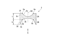
- FIG. 2A is a schematic cross-sectional view including a lens optical axis showing an example of a lens according to the first embodiment of the present invention.
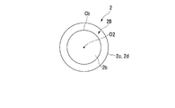
- FIG. 2B is a back view as seen from A in FIG. 2A.
- each drawing is a schematic diagram, dimensions and shapes are appropriately changed (the same applies to the following drawings).
- the lens unit 1 includes a first lens 2 (lens), a second lens 3, and a lens frame 4.
- the first lens 2 and the second lens 3 are arranged coaxially, and are fixed to the lens frame 4 with the axial position of the first lens 2 adjusted at least with respect to the second lens 3.
- the first lens 2 and the lens frame 4 are fixed by the lens fixing structure according to this embodiment.
- lens unit means a group of assemblies in which the lens is fixed to the lens frame.
- the lens unit may be in a form that constitutes a product itself, such as an interchangeable lens, or a semi-finished product such as an exchange unit that constitutes a part of the product, or only a manufacturing process of the product. It may be a subassembly that appears in For example, when fixing a moving lens group and a fixed lens group to separate lens frames in a zoom lens, a lens barrel unit including a moving lens group and a lens barrel unit including a fixed lens group are: Each constitutes a lens unit.
- an axial direction a direction that circulates around the axis
- a circumferential direction a direction along a line that intersects the axis in a plane orthogonal to the axis
- a radial direction a direction along a line that intersects the axis in a plane orthogonal to the axis
- the direction along the optical axis may be referred to as the optical axis direction.
- the direction away from the axis may be referred to as a radially outward (outside), and the direction approaching the axis may be referred to as a radially inward (inside).
- the use of the lens unit 1 is not particularly limited. For example, it can be used for an appropriate optical device such as a photographing lens of a digital camera, a microscope, or a lens used for an endoscope.
- the lens unit 1 is composed of the first lens 2 and the second lens 3 as shown in FIG. 1 as an example, and an appropriate lens configuration according to the application can be adopted. Therefore, for example, the first lens 2 and the second lens 3 are changed to cemented lenses having appropriate configurations, or one or more lenses or lens groups are added between the first lens 2 and the second lens 3. It is also possible.
- the first lens 2 includes a lens portion 2A having a first lens surface 2a (optical surface) and a second lens surface 2b (optical surface), and a connection portion 2B.
- the shape of the 1st lens surface 2a and the 2nd lens surface 2b is not specifically limited, For example, appropriate surface shapes, such as a spherical surface, an aspherical surface, a free-form surface, a plane, are employable.
- the lens portion 2A is a biconcave lens in which the first lens surface 2a and the second lens surface 2b are respectively concave spherical surfaces will be described.
- a flat surface portion 2f made of a plane orthogonal to the lens optical axis O2 (optical axis) is adjacent to the outside of the first lens surface 2a in the radial direction. That is, the inner edge of the flat surface portion 2f is in contact with the outer peripheral portion Ca of the first lens surface 2a formed in a circular shape.
- a connecting portion 2B is provided on the outer side in the radial direction of the second lens surface 2b so as to protrude outward in the axial direction of the lens portion 2A in order to apply an adhesive described later.
- the inner edge of the connection portion 2B is in contact with the outer peripheral portion Cb of the second lens surface 2b formed in a circular shape.
- the side surface of the first lens 2 has a cylindrical lens side surface portion 2c having a diameter larger than that of the outer peripheral portion Ca and coaxial with the lens optical axis O2, and a diameter larger than that of the outer peripheral portion Cb and coaxial with the lens optical axis O2. And a cylindrical surface-shaped outer peripheral surface 2d.
- the cylindrical surface shape is slightly shifted from a strict cylindrical surface such as a shape shifted from the cylindrical surface due to a processing error or a shape having a gradient provided when the lens unit 1 is formed by molding. Including shape.
- the lens side surface portion 2c is a side surface formed in the range of the lens portion 2A
- the outer peripheral surface 2d is a side surface formed in the range of the connection portion 2B.
- the outer diameter of the lens side surface portion 2c and the outer diameter of the outer peripheral surface 2d may be different as long as they are coaxial with the lens optical axis O2, but in this embodiment, as an example, the outer diameter of the lens side surface portion 2c is different.
- the diameter and the outer diameter of the outer peripheral surface 2d are substantially the same (including the same case).
- the boundary between the lens portion 2A and the connection portion 2B is determined by a plane that is orthogonal to the lens optical axis O2 and passes through the outer peripheral portion Cb.
- the lens side surface portion 2c is a portion in the range of the distance t in the direction along the lens optical axis O2 between the outer peripheral portions Ca and Cb, and the outer peripheral surface 2d extends in the axial direction beyond the distance t from the flat surface portion 2f. It is an extended part.
- the connecting portion 2B is a protruding portion from the lens portion 2A.
- the connecting portion 2B has an axial height h and is provided in a substantially cylindrical shape.
- the height h of the connecting portion 2B is required for the strength of the area of the portion inserted into the lens frame 4 when the position of the first lens 2 is adjusted so that the optical characteristics required for the lens unit 1 can be obtained. Decide to exceed the bonding area. For example, if the length h of the outer peripheral surface 2d should be equal to or greater than the upper limit value of the position adjustment amount of the first lens 2, the upper limit value of the axial adjustment amount of the first lens 2 is 100 ⁇ m.
- the length h of the outer peripheral surface 2d may be 100 ⁇ m or more.
- the thickness in the radial direction of the connecting portion 2B is not particularly limited as long as the thickness has a necessary strength when fixed to the lens frame 4, and may be a constant thickness, for example.
- the inner peripheral surface 2e gradually increases from the diameter of the outer peripheral portion Cb of the second lens surface 2b toward the distal end portion in the protruding direction of the connecting portion 2B from the base end portion on the lens portion 2A side. It has a conical shape that expands in diameter and has the same diameter as the outer peripheral surface 2d at the tip. For this reason, the cross-sectional shape of the connecting portion 2B in the radial direction including the lens optical axis O2 is a right triangle whose inner peripheral surface 2e is the hypotenuse.
- the shapes of the proximal end portion and the distal end portion of the connection portion 2B can be deformed into various shapes, for example, for reasons of processing and strength.
- a flat portion perpendicular to the lens optical axis O2 is provided between the base end portion of the inner peripheral surface 2e and the outer peripheral portion Cb, or the inner peripheral surface 2e in the vicinity of the outer peripheral portion Cb is made smooth with the inner peripheral surface 2e. It is also possible to configure with a curved surface to be connected.
- the tip of the inner peripheral surface 2e and the tip of the outer peripheral surface 2d are connected by a convex curved surface having a circular arc cross section, and the tip is rounded, or connected through a flat portion perpendicular to the lens optical axis O2. And it is also possible to make the cross section along a radial direction trapezoid.
- connection portion 2B since the connecting portion 2B applies an adhesive, the connecting portion 2B is more radially along the lens optical axis O2 than the lens side surface portion 2c, more radially outside the outer peripheral portion Cb of the second lens surface 2b, which is an optical surface. Protruding in the direction.
- the connection portion 2B according to the present embodiment is an example in the case of being formed integrally with the lens portion 2A.
- the material of the 1st lens 2 will not be specifically limited if the lens part 2A and the connection part 2B can be formed, For example, glass and a synthetic resin can be employ
- the first lens 2 can be manufactured by, for example, glass molding or glass polishing in the case of glass, or injection molding in the case of synthetic resin. In the present embodiment, the first lens 2 is formed by glass molding as an example.
- the 2nd lens 3 can comprise the optical system according to the use of the lens unit 1 with the 1st lens 2, the lens structure, a material, and a manufacturing method will not be specifically limited. Moreover, the shape of the 2nd lens 3 will not be specifically limited if it can fix to the lens frame 4 mentioned later.
- the fixing method of the 2nd lens 3 and the lens frame 4 is not specifically limited, For example, adhesion
- the second lens 3 is a lens that is adhered and fixed to the lens frame 4 without adjustment before the first lens 2 is fixed. As an example, as shown in FIG.
- the second lens 3 has a first lens surface 3 a and a second lens surface 3 b that are convex surfaces, and a lens side surface between the first lens surface 3 a and the second lens surface 3 b. It consists of a biconvex lens having 3c.
- the lens frame 4 is made of a substantially cylindrical member that inserts and fixes the first lens 2 and the second lens 3 therein.
- the central axis of the outer peripheral surface 4h of the lens frame 4 is referred to as a central axis C.
- the first end E1 (upper side in the drawing) of the lens frame 4 is a hole into which the connecting portion 2B of the first lens 2 is inserted inward, and from the cylindrical surface coaxial with the central axis C inside the first end surface 4f.
- the first inner peripheral surface 4a is formed.
- the first inner peripheral surface 4a inserts at least the connecting portion 2B so as to be movable in the axial direction, and introduces an adhesive into the radial gap with the outer peripheral surface 2d of the connecting portion 2B. Have an inner diameter that can be.
- the inner diameter of the first inner peripheral surface 4a is slightly larger than the outer peripheral surface 2d so that positioning in the radial direction is possible.
- the inner diameter is such that a gap having a size including the adjustment margin in the radial direction is formed between the outer peripheral surface 2d.
- the length of the first inner peripheral surface 4a in the axial direction exceeds the position of the tip of the connecting portion 2B when the first lens 2 is inserted to the maximum within the adjustment range in the axial direction.
- a hole including a second inner peripheral surface 4 b and a second lens receiving portion 4 d is formed at the second end E 2 opposite to the first end E 1 in order to fix the second lens 3.
- the second inner peripheral surface 4 b has an inner diameter into which the second lens 3 can be inserted, and a cylinder that fixes the second lens 3 by introducing an adhesive between the second inner peripheral surface 4 b and the lens side surface 3 c of the inserted second lens 3. Surface.
- the second inner peripheral surface 4b is provided coaxially with the central axis C.
- the second lens receiving portion 4d fixes the position of the second lens 3 in the axial direction by bringing the peripheral edge of the first lens surface 3a of the second lens 3 into contact in the axial direction. It consists of the protrusion part protruded inward of 4b.
- the second lens receiving portion 4d can employ an annular protrusion having a plane perpendicular to the central axis C on the second end E2 side.
- a first lens receiving portion 4c is provided between the first inner peripheral surface 4a and the second lens receiving portion 4d.
- the first lens receiving portion 4c is a part for determining an initial position before the position adjustment of the first lens 2 in the optical axis direction.
- the first lens receiving portion 4c is formed so as to protrude to the inner peripheral side up to a position where it can receive the tip of the connecting portion 2B, similarly to the second lens receiving portion 4d. It is the projected part.
- the position of the first lens receiving portion 4c in the axial direction is not particularly limited as long as it is closer to the second lens receiving portion 4d than the position where the first lens 2 is fixed by adhesion.
- the first lens receiving portion 4c and the second lens receiving portion 4d may be integrated.
- the second lens 3 has the second inner peripheral surface 4b of the lens frame 4 in a state where the first lens surface 3a is in contact with the inner peripheral portion of the second lens receiving portion 4d. Further, the adhesive is fixed via an adhesive portion 6 formed by curing.
- the second lens surface 3b of the second lens 3 may protrude from the second end surface 4g of the second end portion E2, or may be retracted inside the second end surface 4g.
- the position where the bonding portion 6 is formed is not particularly limited as long as it does not overlap the lens effective surfaces of the first lens surface 3a and the second lens surface 3b.
- the adhesive portion 6 is formed by filling and curing an adhesive between at least the lens side surface 3c and the second inner peripheral surface 4b at a plurality of locations in the circumferential direction.
- the second lens surface 3b is disposed so as to be retracted to the inner side in the axial direction from the second end surface 4g, and the adhesive portion 6 is also disposed in the axial direction from the second end surface 4g. It is formed on the inner side.
- the position of the circumferential direction of the adhesion part 6 will not be specifically limited if adhesive strength is acquired, One location of the circumferential direction may be sufficient, and it may be formed over the perimeter.
- the adhesive that forms the bonding portion 6 is not particularly limited as long as it is an adhesive that can bond the second lens 3 to the lens frame 4.
- Examples of the adhesive suitable for forming the adhesive portion 6 include UV (ultraviolet) curable adhesives, two-part adhesives, thermosetting adhesives, and the like.
- a UV curable adhesive is more preferable because it can be quickly fixed because of a short curing time.
- the first lens 2 is fixed to the first inner peripheral surface 4 a of the lens frame 4 and the adhesive in a state where the position adjustment with respect to the second lens 3 is performed after the second lens 3 is fixed. Is fixed through an adhesive portion 5 (cured body of adhesive) formed by curing.
- the first lens 2 can be fixed at an appropriate position according to the design specifications of the lens unit 1 and the result of lens position adjustment described later.
- the first lens 2 may be fixed in a state where the first lens 2 is entirely inserted into the lens frame 4, or a part of the first lens 2 may protrude from the first end face 4 f and be fixed. In FIG.
- the first lens 2 is shown as being fixed such that a part of the lens side surface portion 2 c protrudes outward in the axial direction from the first end surface 4 f of the lens frame 4.
- the adhesive portion 5 introduces an adhesive from the first end surface 4f side between the outer peripheral surface 2d of the connection portion 2B and the first inner peripheral surface 4a of the lens frame 4 at a plurality of locations in the circumferential direction. It is formed by curing.
- the adhesive portion 5 can be provided at one place in the circumferential direction.
- the adhesion part 5 may be provided over the whole circumferential direction.
- the bonding portion 5 is also formed on the outer side in the axial direction from the first end face 4f. For this reason, the adhesion part 5 is formed over the whole axial direction of the lens side part 2c and the outer peripheral surface 2d.
- a UV curable adhesive is employed as the adhesive that forms the adhesive portion 5.
- FIG. 3A is a schematic process explanatory diagram of a lens insertion process of the lens fixing method according to the first embodiment of the present invention.
- FIG. 3B is a schematic process explanatory diagram of an adhesive introduction process of the lens fixing method according to the first embodiment of the present invention.
- FIG. 4A is a schematic process explanatory diagram of a lens holding process of the lens fixing method according to the first embodiment of the present invention.
- FIG. 4B is a schematic process explanatory diagram of the adhesive curing process according to the first embodiment of the present invention.
- the second lens 3 In order to fix the second lens 3 to the lens frame 4, the second lens 3 is inserted into the second inner peripheral surface 4b of the lens frame 4, and the first lens surface 3a is brought into contact with the second lens receiving portion 4d. In this state, an adhesive is applied between the lens side surface 3c and the second inner peripheral surface 4b, and the adhesive is cured. Thereby, the adhesion part 6 is formed and the second lens 3 is fixed to the lens frame 4.
- the lens fixing method according to this embodiment includes a lens insertion step, an adhesive introduction step, a lens holding step, and an adhesive curing step, and these steps are executed in this order.
- the execution order of the adhesive introduction step and the lens holding step can be switched.
- This step is a step of inserting the first lens 2 so that at least the connecting portion 2B is inserted inside the first inner peripheral surface 4a which is a hole provided in the lens frame 4.
- the second end E2 of the lens frame 4 to which the second lens 3 is fixed is held by the holding portion 7a of the fixing base 7.
- the first lens 2 is inserted inside the first inner peripheral surface 4a of the lens frame 4, and the first lens 2 is received by the first lens receiving portion 4c.
- the first lens 2 can be inserted into the lens frame 4 by any means. For example, it can be inserted manually using tweezers or a vacuum pick.
- at least the outer peripheral surface 2d is in a state of being inserted inside the first inner peripheral surface 4a. This is the end of the lens insertion process.
- the outer peripheral surface 2d inserted inside the first inner peripheral surface 4a may be a part or the whole of the outer peripheral surface 2d as long as a necessary adhesion area can be secured.
- a part or all of the lens side surface portion 2c may be inserted into the first inner peripheral surface 4a.
- an adhesive introduction process is performed.
- at least the connecting portion 2B of the first lens 2 is inserted inside the first inner peripheral surface 4a of the lens frame 4, and the adhesive is at least between the connecting portion 2B and the first inner peripheral surface 4a.
- a predetermined amount of UV curable adhesive 5 ⁇ / b> A is dropped from the tip of the adhesive supply unit 14, and the UV curable adhesive 5 ⁇ / b> A is applied to the side surface of the first lens 2.
- the UV curable adhesive 5A falls into the gap between the outer peripheral surface 2d and the first inner peripheral surface 4a, it spreads inside the gap due to surface tension. Thereby, the UV curable adhesive 5A is introduced into the gap between the outer peripheral surface 2d and the first inner peripheral surface 4a, and the UV curable adhesive 5A is applied to the outer peripheral surface 2d.
- the dripping amount and viscosity of the UV curable adhesive 5A are determined by the surface tension depending on the size of the gap formed between the outer peripheral surface 2d and the first inner peripheral surface 4a. The value is appropriately adjusted in advance so that the agent 5A is retained.
- the UV curable adhesive 5A is introduced by moving the adhesive supply unit 14 as necessary so that the UV curable adhesive 5A is applied to all the portions where the adhesive portion 5 is formed. Go. At this time, when the lens side surface portion 2c is inserted into the first inner peripheral surface 4a, the UV curable adhesive 5A is also introduced between the lens side surface portion 2c and the first inner peripheral surface 4a. . Further, the application range of the UV curable adhesive 5A is not limited between the side surface of the first lens 2 and the first inner peripheral surface 4a. For example, as shown to FIG. 3A, you may apply
- the UV curable adhesive 5A when the UV curable adhesive 5A is supplied to the side surface of the first lens 2 projecting outside the first inner peripheral surface 4a, the UV curable adhesive 5A flows smoothly along the side surface of the first lens 2. And introduced into the gap with the first inner peripheral surface 4a. This is the end of the adhesive introduction process.
- This step is a step of holding the first lens 2 at a fixed position with respect to the lens frame 4.
- the fixing position of the first lens 2 with respect to the lens frame 4 is such that the optical characteristics of the lens unit 1 are predetermined in the relative positional relationship between the lens frame 4 and the second lens 3 fixed to the lens frame 4. Is the position.
- Such a fixed position is determined based on measurement of optical characteristics or the like.
- the optical characteristics are measured by a measuring device (not shown), and the position of the first lens 2 is adjusted with respect to the second lens 3 as shown in FIG. Decide.
- optical characteristics that can be used for such position adjustment include, for example, the wavefront of the measurement light Lm that has passed through the first lens 2 when the measurement light Lm is incident on the second lens 3 and the first lens 2. Aberrations can be mentioned.
- An operator uses the suction jig 10 to suck the flat surface portion 2f of the first lens 2, and based on the measured wavefront aberration, the suction jig moving section 11 including the moving arm 11a that moves the suction jig 10. And the position of the first lens 2 adsorbed on the suction jig 10 is adjusted until the wavefront aberration is below the allowable limit. At this time, since the UV curable adhesive 5A is in an uncured state, the UV curable adhesive 5A appropriately flows as the first lens 2 moves. For this reason, the UV curable adhesive 5A does not hinder position adjustment.
- the lens optical axis O2 of the first lens 2 is substantially aligned with the lens optical axis of the second lens 3 (including the case where it is aligned), and includes the second lens 3 and the first lens 2.
- the wavefront aberration of the optical system coincides with a predetermined design value within an allowable range.
- an adhesive curing step is performed.
- the UV curable adhesive 5A introduced between the first lens 2 and the first inner peripheral surface 4a in the adhesive introduction step is cured. It is a process.
- the operator turns on the UV light source 12 and irradiates the UV light L UV toward the UV curable adhesive 5A, thereby curing the UV curable adhesive 5A.
- the UV light source 12 is arranged so that the UV light L UV can be irradiated to the outer peripheral portion of the first lens 2 and the first end E1 of the lens frame 4 from obliquely upward outside in the radial direction. For this reason, the UV light L UV radiated from the UV light source 12 is irradiated to the UV curable adhesive 5A through various paths.
- part of the UV light L UV reaches the UV curable adhesive 5A directly from above. Further, a part of the UV light L UV reaches the UV curable adhesive 5A after being reflected by the lens side surface portion 2c protruding outward from the first lens surface 2a. Further, a part of the UV light L UV passes through the lens portion 2A and the connection portion 2B from the outer peripheral portion of the first lens 2 protruding outward from the first lens surface 2a, thereby sandwiching the central axis C. The UV curable adhesive 5A at the opposite side is reached.
- the UV curable adhesive 5A is evenly irradiated with the UV light L UV, so that adhesion failure is prevented, and the UV curable adhesive 5A is cured to form the adhesive portion 5. .
- the problem can be solved by securing a necessary irradiation amount such as arranging a plurality of UV light sources 12. The adhesive curing process is thus completed.
- the 1st lens 2 is provided with the connection part 2B, and can adhere
- the bonding area varies depending on the position adjustment amount for each lens unit, but the bonding area is larger than the case where the connection portion 2B is not provided. Since it has increased more, the relative dispersion
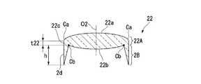
- FIG. 5A is a schematic cross-sectional view including the lens optical axis of a lens according to a modified example (first modified example) of the first embodiment of the present invention.
- a first lens 22 of this modification shown in FIG. 5A is a lens that can be used in the lens unit 1 in place of the first lens 2 of the first embodiment.
- the first lens 22 includes a lens portion 22A instead of the lens portion 2A of the first lens 2 according to the first embodiment.
- a description will be given centering on differences from the first embodiment.
- the lens portion 22A is different from the lens portion 2A of the first lens 2 according to the first embodiment in that the lens portion 22A is a biconvex lens, whereas the lens portion 2A is a biconcave lens. That is, the lens portion 22A includes a first lens surface 22a (optical surface) formed of a convex surface instead of the first lens surface 2a and the flat surface portion 2f of the lens portion 2A, and includes a convex surface instead of the second lens surface 2b. A second lens surface 22b (optical surface) is provided.
- the lens side surface portion 22c in the lens portion 22A is within a range of a distance t22 in the direction along the lens optical axis O2 between the outer peripheral portion Ca of the first lens surface 22a and the outer peripheral portion Cb of the second lens surface 22b. It consists of a cylindrical surface coaxial with the formed lens optical axis O2.
- the first lens 22 is different only in that the lens shape of the lens portion 22A is a biconvex lens, the first lens 22 is fixed to the lens frame 4 by the lens fixing method according to the first embodiment. be able to. Thereby, a lens unit whose optical system is composed of the first lens 22 and the second lens 3 can be manufactured.
- the length t22 of the lens side surface portion 22c of the first lens 22 is often shorter than the length t of the lens side surface portion 2c of the first lens 2 that is a biconcave lens.
- the connection portion 2B since the connection portion 2B is provided, the position adjustment can be performed and the lens frame 4 can be adhered and fixed just like the first lens 2.
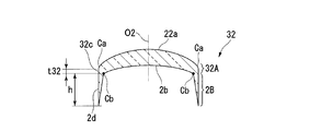
- FIG. 5B is a schematic cross-sectional view including the lens optical axis of a lens according to a modification (second modification) of the first embodiment of the present invention.
- the first lens 32 of this modification shown in FIG. 5B is a lens that can be used in the lens unit 1 instead of the first lens 2 of the first embodiment.
- the first lens 32 includes a lens portion 32A instead of the lens portion 2A of the first lens 2 of the first embodiment.
- a description will be given centering on differences from the first embodiment.
- the lens part 32A is different from the lens part 2A of the first lens 2 according to the first embodiment in that the lens part 2A is a biconcave lens, whereas the lens part 32A is a convex meniscus lens on the opposite side to the connection part 2B. That is, the lens portion 32A includes a first lens surface 22a similar to that of the first modified example, instead of the first lens surface 2a and the flat surface portion 2f of the lens portion 2A. For this reason, the lens side surface portion 32c in the lens portion 32A is in a range of a distance t32 in the direction along the lens optical axis O2 between the outer peripheral portion Ca of the first lens surface 22a and the outer peripheral portion Cb of the second lens surface 2b. It consists of a cylindrical surface coaxial with the formed lens optical axis O2. 5B shows an example in which the lens portion 32A is a positive meniscus lens, it may be a negative meniscus lens.
- Such a first lens 32 differs only in that the lens shape of the lens portion 2A is a meniscus lens that is convex on the opposite side to the connection portion 2B. Therefore, the first lens 32 is different from the lens fixing method of the first embodiment. 32 can be fixed to the lens frame 4. Thereby, a lens unit whose optical system is composed of the first lens 32 and the second lens 3 can be manufactured.
- the length t32 of the lens side surface portion 32c of the first lens 32 is often shorter than the length t of the lens side surface portion 2c of the first lens 32, particularly in the case of a positive meniscus lens. .
- the connection portion 2B since the connection portion 2B is provided, the position adjustment can be performed and the lens frame 4 can be adhered and fixed just like the first lens 2.
- FIG. 5C is a schematic cross-sectional view including the lens optical axis of a lens according to a modification (third modification) of the first embodiment of the present invention.
- a first lens 42 of the present modification shown in FIG. 5C is a lens that can be used in the lens unit 1 instead of the first lens 2 according to the first embodiment.
- the first lens 42 includes a lens portion 42A instead of the lens portion 2A of the first lens 2 according to the first embodiment.
- a description will be given centering on differences from the first embodiment.
- the lens portion 42A is different from the lens portion 2A of the first lens 2 of the first embodiment in that it is a meniscus lens that is convex on the connection portion 2B side, whereas the lens portion 2A is a biconcave lens. That is, the lens unit 32A includes a second lens surface 22b similar to that of the first modified example, instead of the second lens surface 2b of the lens unit 2A. For this reason, the lens side surface portion 42c in the lens portion 42A is within the range of the distance t42 in the direction along the lens optical axis O2 between the outer peripheral portion Ca of the first lens surface 2a and the outer peripheral portion Cb of the second lens surface 22b. It consists of a cylindrical surface coaxial with the formed lens optical axis O2. 5C shows an example in which the lens portion 42A is a positive meniscus lens, it may be a negative meniscus lens.
- Such a first lens 42 differs only in that the lens shape of the lens portion 2A is a meniscus lens convex to the connection portion 2B side. Therefore, the first lens 42 is changed by the lens fixing method of the first embodiment. It can be fixed to the lens frame 4. Thereby, a lens unit whose optical system is composed of the first lens 42 and the second lens 3 can be manufactured.
- the length t42 of the lens side surface portion 42c of the first lens 42 is often shorter than the length t of the lens side surface portion 2c of the first lens 2 which is a biconcave lens, particularly in the case of a positive meniscus lens. .
- the connection portion 2B since the connection portion 2B is provided, the position adjustment can be performed and the lens frame 4 can be adhered and fixed just like the first lens 2.
- FIG. 6A is a schematic cross-sectional view including a lens optical axis showing an example of a lens of a modified example (fourth modified example) of the first embodiment of the present invention.
- 6B is a rear view of FIG. 6A viewed from B.
- FIG. 6A is a schematic cross-sectional view including a lens optical axis showing an example of a lens of a modified example (fourth modified example) of the first embodiment of the present invention.
- 6B is a rear view of FIG. 6A viewed from B.
- a first lens 52 of this modification shown in FIGS. 6A and 6B is a lens that can be used in the lens unit 1 instead of the first lens 2 of the first embodiment.
- the first lens 52 includes a connection portion 52B instead of the connection portion 2B of the first lens 2 of the first embodiment.
- connection portion 52B instead of the connection portion 2B of the first lens 2 of the first embodiment.
- connection part 2B of the first lens 2 is a protrusion extending over the entire circumference of the lens part 2A
- the connection part 52B of this modification is spaced apart in the circumferential direction.
- the protrusions are provided at a plurality of locations. That is, in the first lens 52, a planar portion 52g parallel to the planar portion 2f is formed adjacent to the outer peripheral portion Cb of the second lens surface 2b, and a region of thickness t between the planar portions 2f and 52g.
- a lens portion 2A is formed on the surface.
- connection part 52B is provided in the range of the height h from 3 positions which divide the circumferential direction into 3 equally on the plane part 52g.
- connection portion 52B The cross-sectional shape along the radial direction of the connection portion 52B is a right triangle similar to the connection portion 2B.
- the connection portion 52B includes an outer peripheral surface 52d and an inner peripheral surface 52e corresponding to the outer peripheral surface 2d and the inner peripheral surface 2e of the connection portion 2B, respectively.
- the outer peripheral surface 52d is a partial cylindrical surface obtained by extending the lens side surface portion 2c in the axial direction.
- the length in the circumferential direction of the outer peripheral surface 52d is set to an appropriate length capable of holding the UV curable adhesive 5A that provides the necessary adhesive strength.
- the inner peripheral surface 52e gradually increases in diameter from the diameter of the outer peripheral portion Cb of the second lens surface 2b from the base end portion on the lens portion 2A side toward the distal end portion in the protruding direction, and is the same as the outer peripheral surface 2d at the distal end portion. It has a conical surface shape with a diameter. For this reason, the cross-sectional shape in the radial direction including the lens optical axis O2 is a right triangle whose inner peripheral surface 52e is a hypotenuse.
- connection part 52B having such a configuration can be formed by molding, or can be formed by removing a part of the connection part 2B after forming the connection part 2B.
- the cross-sectional shape in the radial direction of the connecting portion 52B described above is an example, and may be, for example, a rectangular shape or a trapezoidal shape, or may include a flat portion or a curved portion between the outer peripheral portion Cb. What is good is the same as the cross-sectional shape of the connecting portion 2B in the first embodiment.
- the first lens 52 is different only in that the connection portion 52B is provided only at the portion where the bonding portion 5 is formed, the first lens 52 is made into a lens by the lens fixing method of the first embodiment. It can be fixed to the frame 4. Thereby, a lens unit having the same optical system as the lens unit 1 can be manufactured.
- connection portion 52B is provided only at the portion where the bonding portion 5 is formed, and thus it is possible to reduce the weight compared to the first lens 2.
- FIG. 7 is a schematic cross-sectional view including an optical axis showing an example of a lens unit having a lens fixing structure according to the second embodiment of the present invention.
- FIG. 8A is a schematic cross-sectional view including a lens optical axis showing an example of a lens according to the second embodiment of the present invention.
- FIG. 8B is a back view as viewed from D in FIG. 8A.
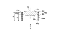
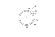
- a lens unit 61 includes a first lens assembly 62 (lens) instead of the first lens 2 of the lens unit 1 of the first embodiment.
- the first lens assembly 62 includes a lens body 63 and a connection member 64 (connection portion).
- the lens body 63 can employ a lens or a lens group having an appropriate configuration.
- the lens body 63 includes a convex first lens surface 63a (optical surface) and a convex second lens surface 63b (optical surface) arranged on the lens optical axis O2.
- a lens side surface 63c (lens side surface portion) composed of a cylindrical surface coaxial with the lens optical axis O2 is formed.
- the material of the lens body 63 is not particularly limited as long as the connection member 64 can be fixed on the lens side surface 63c.
- glass or synthetic resin can be used.
- the lens body 63 can be manufactured by, for example, glass molding or glass polishing in the case of glass, or injection molding in the case of synthetic resin. In the present embodiment, the lens body 63 is formed by glass molding as an example.
- the inner diameter of the inner peripheral surface 64b of the connection member 64 is set to an appropriate dimension that allows the lens side surface 63c to be fitted externally according to the fixing method with the lens side surface 63c.
- a fixing method such as adhesion, fusion, caulking, or press fitting can be employed.
- bonding is employed as an example.
- the adhesive the same adhesive as that for forming the adhesive portion 6 can be employed.
- the outer diameter of the outer peripheral surface 64a of the connecting member 64 is set to a dimension that can be inserted into the first inner peripheral surface 4a to adjust the position, similarly to the outer peripheral surface 2d according to the first embodiment. . That is, when the position of the first lens assembly 62 is adjusted only in the axial direction, the outer diameter is slightly smaller than the first inner peripheral surface 4a of the lens frame 4 so that the radial positioning is possible. . In addition, when the position of the first lens assembly 62 is adjusted in the axial direction and the radial direction, an outer diameter having such a size that a gap including a radial adjustment margin is formed between the first lens assembly 62 and the first inner peripheral surface 4a. To do.
- connection member 64 is not particularly limited, and for example, metal, synthetic resin, or the like can be used.
- the first lens assembly 62 adjusts the position relative to the second lens 3 after fixing the second lens 3 to the lens frame 4 in the same manner as in the first embodiment. In the performed state, it is bonded and fixed by the lens fixing method of the first embodiment.
- connection member 64 protrudes in the axial direction instead of the connection portion 2B of the first lens 2 according to the first embodiment. That is, the connection member 64 is a cylindrical member having one end fixed to the lens side surface 63c. Further, since the UV curable adhesive 5A is applied, the connection member 64 is provided so as to protrude in the direction along the lens optical axis O2 from the lens side surface 63c on the radial outside of the outer peripheral portion of the second lens surface 63b.
- the connection part is configured.
- the present embodiment is an example in the case where the connection portion is formed by a connection member 64 having a cylindrical portion with one end fixed to the lens side surface 63c and protruding to the other end side. Therefore, in the lens unit 61, a lens fixing structure similar to that of the first embodiment is formed between the first lens assembly 62 and the lens frame 4.
- the first lens assembly 62 is fixed to the lens frame 4 by the same lens fixing method as in the first embodiment except that the first lens assembly 62 is used instead of the first lens 2. be able to. Thereby, the lens unit 61 can be manufactured.
- the first lens assembly 62 includes the connection member 64 serving as a connection portion, so that the first lens assembly 62 and the first lens assembly 62 can be compared with the case where the first lens assembly 62 is bonded only at the side portion of the lens body 63.
- the adhesion area of the lens frame 4 can be increased.
- FIG. 9A is a schematic cross-sectional view including a lens optical axis showing an example of a lens of a modified example (fifth modified example) of the second embodiment of the present invention.
- FIG. 9B is a rear view of FIG. 9A viewed from E.
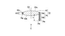
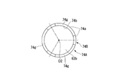
- a first lens assembly 72 of this modification shown in FIGS. 9A and 9B is a lens that can be used in the lens unit 61 in place of the first lens assembly 62 of the second embodiment.
- the first lens assembly 72 includes a connection member 74 (connection portion) instead of the connection member 64 of the second embodiment.
- connection member 74 connection portion
- connection member 64 of the first lens assembly 62 according to the second embodiment is a protrusion that extends over the entire circumference of the lens side surface 63c
- the connection member 74 of this modification example has a circumferential direction.
- the point which has the projection part provided in the several places to space apart is different. That is, the connecting member 74 extends in the axial direction at a plurality of locations spaced in the circumferential direction of the annular portion 74A that is fitted over the entire circumference of the lens side surface 63c and the end portion of the annular portion 74A on the second lens surface 63b side.
- a piece-like connecting portion 74B is a piece-like connecting portion 74B.
- connection portions 74B can be appropriately set according to the forming position of the bonding portion 5 for obtaining a predetermined bonding strength.
- connection portions 74B having the same shape are projected at three positions that divide the circumferential direction into three equal parts.
- the length in the axial direction of the connecting portion 74 ⁇ / b> B is the same length h as the protruding amount in the connecting member 64.
- the outer peripheral surface and the inner peripheral surface of the connection portion 74B are configured by cylindrical surfaces aligned with the outer peripheral surface 74a and the inner peripheral surface 74b in the annular portion 74A, respectively.
- the outer peripheral surface 74a and the inner peripheral surface 74b are respectively formed of cylindrical surfaces similar to the outer peripheral surface 64a and the inner peripheral surface 64b of the second embodiment.
- This modification is an example in which the connection portion 74B is formed by a connection member 74 having one piece fixed to the lens side surface 63c and having a piece-like portion protruding to the other end side.
- connection member 74 having such a configuration can be formed by molding, or can be formed by removing a part of the connection member 64 after forming the connection member 64.
- the first lens assembly 72 differs only in that the connection portion 74B is provided only at a portion where the bonding portion 5 is formed, the first lens assembly 72 is provided with the lens fixing method according to the first embodiment.
- the assembly 72 can be fixed to the lens frame 4. Thereby, a lens unit having the same optical system as the lens unit 61 can be manufactured.
- connection portion 74B is provided only at the site where the bonding portion 5 is formed, and thus it is possible to reduce the weight compared to the first lens assembly 62. It is.
- the adhesive used may be an adhesive that cures when irradiated with light or energy rays having a wavelength other than UV light.
- connection member 74 has a piece-like connection portion 74B, and the connection portion 74B is fixed to the lens side surface 63c via the annular portion 74A.
- the annular portion 74A is not an essential configuration.
- a configuration in which a piece-like connection portion having an arc-shaped cross section along the lens side surface 63c is directly fixed to the lens side surface 63c by bonding or the like is also possible.
- Each of the above-described embodiments includes a lens fixing structure, a lens, a lens unit, and a lens fixing method that provide good adhesive strength even when the position is fixed by bonding after adjusting the position of the lens. Can be provided.
Landscapes
- Physics & Mathematics (AREA)
- General Physics & Mathematics (AREA)
- Optics & Photonics (AREA)
- Lens Barrels (AREA)
Abstract
本レンズ固定構造は、接着によってレンズをレンズ枠に固定するレンズ固定構造であって、前記レンズは、複数の光学面を有するレンズ部と、前記複数の光学面のうち光軸に沿う方向の両端に位置する光学面の外周部で挟まれた領域の側面であるレンズ側面部と、接着剤を塗布するため、前記光学面の外周部よりも径方向外側において、前記レンズ側面部よりも前記光軸に沿う方向に突出して設けられた接続部と、を有し、前記レンズ枠は、前記接続部を内側に挿入する穴部を有し、少なくとも前記接続部と前記穴部の内周面との間に前記接着剤の硬化体を設けて、前記レンズと前記レンズ枠とを固定する。
Description
本発明は、レンズ固定構造、レンズ、レンズユニット、およびレンズ固定方法に関する。
本願は、2014年04月01日に、日本国に出願された特願2014-075444号に基づき優先権を主張し、その内容をここに援用する。
本願は、2014年04月01日に、日本国に出願された特願2014-075444号に基づき優先権を主張し、その内容をここに援用する。
従来、レンズを移動可能に保持して光軸に沿う方向の位置調整を行い、その調整位置を保持した状態で、レンズを接着固定する方法が知られている。
例えば、特許文献1には、位置調整後に接着固定されたレンズ一体型撮像装置が記載されている。このレンズ一体型撮像装置の製造方法は、レンズ保持部に保持された状態のレンズを、撮像チップが固定されたパッケージに対して位置調整し、レンズ保持部における光軸に沿う方向の先端部とパッケージとの間に紫外線硬化型の接着剤を塗布して硬化させる。これにより、レンズと撮像チップとの位置関係が固定される。このため、硬化した接着剤は、レンズの光軸に沿う方向の位置を調整する位置調整部材としての機能を有している(特許文献1参照)。
例えば、特許文献1には、位置調整後に接着固定されたレンズ一体型撮像装置が記載されている。このレンズ一体型撮像装置の製造方法は、レンズ保持部に保持された状態のレンズを、撮像チップが固定されたパッケージに対して位置調整し、レンズ保持部における光軸に沿う方向の先端部とパッケージとの間に紫外線硬化型の接着剤を塗布して硬化させる。これにより、レンズと撮像チップとの位置関係が固定される。このため、硬化した接着剤は、レンズの光軸に沿う方向の位置を調整する位置調整部材としての機能を有している(特許文献1参照)。
しかしながら、上記のような従来技術には、以下のような問題があった。
特許文献1に記載の技術では、レンズの位置調整を行うと、パッケージとレンズ保持部との間の間隔が変化する。この間隔が大きくなりすぎると、接着剤を安定して保持することができなくなり、接着剤の硬化後の接着強度が低下してしまうという問題がある。
安定した接着強度を得るために、例えば、レンズ保持部とパッケージとの対向面積を大きくしたり、調整範囲を狭めたりすることも考えられる。
しかし、レンズ保持部とパッケージとの対向面積を大きくすると、接着剤にむら無く紫外線を照射することが難しくなり、接着不良が発生するおそれがある。また、レンズ保持部の径が大きくなるため、装置の外形が大きくなってしまうという問題がある。
また、調整範囲を狭めると、他部材の配置精度を高める必要がある。この場合、部品精度や組立精度を高めなければならず、製造コストが増大する問題がある。
特許文献1に記載の技術では、レンズの位置調整を行うと、パッケージとレンズ保持部との間の間隔が変化する。この間隔が大きくなりすぎると、接着剤を安定して保持することができなくなり、接着剤の硬化後の接着強度が低下してしまうという問題がある。
安定した接着強度を得るために、例えば、レンズ保持部とパッケージとの対向面積を大きくしたり、調整範囲を狭めたりすることも考えられる。
しかし、レンズ保持部とパッケージとの対向面積を大きくすると、接着剤にむら無く紫外線を照射することが難しくなり、接着不良が発生するおそれがある。また、レンズ保持部の径が大きくなるため、装置の外形が大きくなってしまうという問題がある。
また、調整範囲を狭めると、他部材の配置精度を高める必要がある。この場合、部品精度や組立精度を高めなければならず、製造コストが増大する問題がある。
本発明は、上記のような課題に鑑みてなされたものであり、レンズの位置調整を行って接着により位置を固定する場合にも、接着強度が良好になるレンズ固定構造、レンズ、レンズユニット、およびレンズ固定方法を提供することを目的とする。
本発明の第1の態様によれば、レンズ固定構造は、接着によってレンズをレンズ枠に固定するレンズ固定構造であって、前記レンズは、複数の光学面を有するレンズ部と、前記複数の光学面のうち光軸に沿う方向の両端に位置する光学面の外周部で挟まれた領域の側面であるレンズ側面部と、接着剤を塗布するため、前記光学面の外周部よりも径方向外側において、前記レンズ側面部よりも前記光軸に沿う方向に突出して設けられた接続部と、を有し、前記レンズ枠は、前記接続部を内側に挿入する穴部を有し、少なくとも前記接続部と前記穴部の内周面との間に前記接着剤の硬化体を設けて、前記レンズと前記レンズ枠とを固定したレンズ固定構造である。
本発明の第2の態様によれば、上記第1の態様に係るレンズ固定構造においては、前記接続部は、前記レンズ部と一体に形成されていてもよい。
本発明の第3の態様によれば、上記第1の態様に係るレンズ固定構造においては、前記接続部は、前記レンズ側面部に一端が固定され、他端側に突出された片状部または筒状部を有する接続部材によって形成されていてもよい。
本発明の第4の態様によれば、上記第1の態様から第3の態様のいずれか1つの態様に係るレンズ固定構造においては、前記接着剤は、紫外線硬化型接着剤からなっていてもよい。
本発明の第5の態様によれば、レンズユニットは、上記第1の態様から第4の態様のいずれか1つの態様に係るレンズ固定構造を有する。
本発明の第6の態様によれば、レンズは、複数の光学面を有するレンズ部と、前記複数の光学面のうち光軸に沿う方向の両端に位置する光学面の外周部で挟まれた領域の側面であるレンズ側面部と、接着剤を塗布するため、前記光学面の外周部よりも径方向外側において、前記レンズ側面部よりも前記光軸に沿う方向に突出して設けられた接続部とを有する。
本発明の第7の態様によれば、上記第6の態様に係るレンズにおいては、前記接続部は、前記レンズ部および前記レンズ側面部と一体に形成されていてもよい。
本発明の第8の態様によれば、上記第6の態様に係るレンズにおいては、前記接続部は、前記レンズ側面部に一端が固定され、他端側に突出された片状部または筒状部を有する接続部材によって形成されていてもよい。
本発明の第9の態様によれば、レンズ固定方法は、接着によってレンズをレンズ枠に固定するレンズ固定方法であって、前記レンズは、複数の光学面を有するレンズ部と、前記光学面のうち光軸に沿う方向の両端に位置する光学面の外周部で挟まれた領域の側面であるレンズ側面部と、接着剤を塗布するため、前記光学面の外周部よりも径方向外側において、前記レンズ側面部よりも前記光軸に沿う方向に突出して設けられた接続部と、を有し、前記レンズ枠に設けられた穴部の内側に、少なくとも前記レンズの前記接続部が挿入された状態で、少なくとも前記接続部と前記穴部の内周面との間に接着剤を導入する接着剤導入工程と、前記レンズを前記レンズ枠に対する固定位置に保持するレンズ保持工程と、前記接着剤導入工程および前記レンズ保持工程が実行された後に、前記接着剤導入工程において導入された前記接着剤を硬化させる接着剤硬化工程と、を有する。
本発明の第10の態様によれば、上記第9の態様に係るレンズ固定方法においては、前記レンズ保持工程において、前記穴部の内側で、少なくとも前記光軸に沿う方向に前記レンズを移動して、前記レンズの位置調整を行って、前記固定位置を決めてもよい。
上記各態様に係るレンズ固定構造、レンズ、レンズユニット、およびレンズ固定方法によれば、レンズに光学面の外周部よりも径方向外側において、レンズ側面部よりも光軸に沿う方向に突出する接続部を設けて、接続部と穴部の内周面とを接着するため、レンズ側面部のみを接着する場合に比べて、レンズ枠に対する接着面積を増大することができるため、レンズの位置調整を行い、接着により位置を固定する場合にも、接着強度が良好になる。
以下では、本発明の実施形態について添付図面を参照して説明する。すべての図面において、実施形態が異なる場合であっても、同一または相当する部材には同一の符号を付し、共通する説明は省略する。
[第1の実施形態]
本発明の第1の実施形態に係るレンズ固定構造、レンズ、およびレンズユニットについて説明する。
図1は、本発明の第1の実施形態のレンズ固定構造を備えるレンズユニットの一例を示す光軸を含む模式的な断面図である。図2Aは、本発明の第1の実施形態のレンズの一例を示すレンズ光軸を含む模式的な断面図である。図2Bは、図2AにおけるA視の裏面図である。
なお、各図面は、模式図のため、寸法や形状は適宜異ならせている(以下の図面も同様)。
本発明の第1の実施形態に係るレンズ固定構造、レンズ、およびレンズユニットについて説明する。
図1は、本発明の第1の実施形態のレンズ固定構造を備えるレンズユニットの一例を示す光軸を含む模式的な断面図である。図2Aは、本発明の第1の実施形態のレンズの一例を示すレンズ光軸を含む模式的な断面図である。図2Bは、図2AにおけるA視の裏面図である。
なお、各図面は、模式図のため、寸法や形状は適宜異ならせている(以下の図面も同様)。
図1に示すように、本実施形態に係るレンズユニット1は、第1レンズ2(レンズ)、第2レンズ3、およびレンズ枠4を備える。
第1レンズ2と第2レンズ3とは、同軸に配置され、少なくとも第2レンズ3に対して第1レンズ2の軸方向の位置が調整された状態で、レンズ枠4に固定されている。
特に、第1レンズ2とレンズ枠4とは、本実施形態に係るレンズ固定構造によって固定されている。
第1レンズ2と第2レンズ3とは、同軸に配置され、少なくとも第2レンズ3に対して第1レンズ2の軸方向の位置が調整された状態で、レンズ枠4に固定されている。
特に、第1レンズ2とレンズ枠4とは、本実施形態に係るレンズ固定構造によって固定されている。
ここで、「レンズユニット」とは、レンズがレンズ枠に固定されたひとまとまりの組立体を意味する。このため、レンズユニットは、例えば、交換レンズのように、それ自体が製品を構成する形態であってもよいし、製品の一部を構成する交換ユニット等の半製品や、製品の製造工程のみに現れる部分組立体であってもよい。例えば、ズームレンズにおいて移動レンズ群と、固定レンズ群とをそれぞれ別個のレンズ枠である鏡筒に固定する場合、移動レンズ群を含む鏡筒ユニットと、固定レンズ群を含む鏡筒ユニットとは、それぞれレンズユニットを構成している。
本明細書では、例えば、中心軸線Cや各レンズのレンズ光軸のように中心軸線等の軸線が特定できる軸状、筒状等の部材に関する相対位置について説明する場合に、軸線に沿う方向を軸方向、軸線回りに周回する方向を周方向、軸線に直交する平面において軸線に交差する線に沿う方向を径方向と称する場合がある。また、特に、光軸に沿う方向を光軸方向と称する場合がある。また、径方向においては、軸線から離れる方を径方向外方(外側)、軸線に近づく方を径方向内方(内側)と称する場合がある。
レンズユニット1の用途は、特に限定されない。例えば、デジタルカメラの撮影レンズ、顕微鏡、内視鏡に用いるレンズ等の適宜の光学機器に用いることが可能である。
また、レンズユニット1を図1に示すような第1レンズ2と第2レンズ3とで構成するのは一例であって、用途に応じた適宜のレンズ構成を採用することができる。したがって、例えば、第1レンズ2、第2レンズ3を適宜構成の接合レンズに変更したり、第1レンズ2と第2レンズ3との間に、1以上のレンズまたはレンズ群を追加したりすることも可能である。
また、レンズユニット1を図1に示すような第1レンズ2と第2レンズ3とで構成するのは一例であって、用途に応じた適宜のレンズ構成を採用することができる。したがって、例えば、第1レンズ2、第2レンズ3を適宜構成の接合レンズに変更したり、第1レンズ2と第2レンズ3との間に、1以上のレンズまたはレンズ群を追加したりすることも可能である。
第1レンズ2は、図2Aに示すように、第1レンズ面2a(光学面)、第2レンズ面2b(光学面)を有するレンズ部2Aと、接続部2Bとを備える。
第1レンズ面2a、第2レンズ面2bの形状は、特に限定されず、例えば、球面、非球面、自由曲面、平面等の適宜の面形状を採用することができる。
以下では、レンズ部2Aが、一例として、第1レンズ面2a、第2レンズ面2bがそれぞれ凹球面からなる両凹レンズの場合の例で説明する。
第1レンズ面2a、第2レンズ面2bの形状は、特に限定されず、例えば、球面、非球面、自由曲面、平面等の適宜の面形状を採用することができる。
以下では、レンズ部2Aが、一例として、第1レンズ面2a、第2レンズ面2bがそれぞれ凹球面からなる両凹レンズの場合の例で説明する。
第1レンズ面2aの径方向外方には、レンズ光軸O2(光軸)に直交する平面からなる平面部2fが隣接している。すなわち、平面部2fの内縁は、円状に形成された第1レンズ面2aの外周部Caと接している。
第2レンズ面2bの径方向外方には、後述する接着剤を塗布するため、レンズ部2Aの軸方向の外方に突出するように接続部2Bが設けられている。本実施形態では、一例として、接続部2Bの内縁は、円状に形成された第2レンズ面2bの外周部Cbと接している。
第2レンズ面2bの径方向外方には、後述する接着剤を塗布するため、レンズ部2Aの軸方向の外方に突出するように接続部2Bが設けられている。本実施形態では、一例として、接続部2Bの内縁は、円状に形成された第2レンズ面2bの外周部Cbと接している。
第1レンズ2の側面は、外周部Caよりも大径でレンズ光軸O2と同軸に形成された円筒面状のレンズ側面部2cと、外周部Cbよりも大径でレンズ光軸O2と同軸に形成された円筒面状の外周面2dとを備える。
ここで、円筒面状とは、例えば、加工誤差によって円筒面からずれた形状や、レンズユニット1を成形で形成する場合に設けられた勾配を有する形状等の厳密な円筒面からわずかにずれた形状も含む。
ここで、円筒面状とは、例えば、加工誤差によって円筒面からずれた形状や、レンズユニット1を成形で形成する場合に設けられた勾配を有する形状等の厳密な円筒面からわずかにずれた形状も含む。
レンズ側面部2cは、レンズ部2Aの範囲に形成された側面であり、外周面2dは、接続部2Bの範囲に形成された側面である。
レンズ側面部2cの外径と、外周面2dの外径とは、レンズ光軸O2と同軸であれば、それぞれ異なっていてもよいが、本実施形態では、一例として、レンズ側面部2cの外径と、外周面2dの外径とは、略同一(同一の場合を含む)径になっている。
レンズ部2Aと接続部2Bとの境界は、レンズ光軸O2に直交し外周部Cbを通る平面で定める。すなわち、レンズ側面部2cは、外周部Ca、Cb間のレンズ光軸O2に沿う方向の距離tの範囲の部位であり、外周面2dは、平面部2fからの距離tを越えて軸方向に延ばされた部位である。
レンズ側面部2cの外径と、外周面2dの外径とは、レンズ光軸O2と同軸であれば、それぞれ異なっていてもよいが、本実施形態では、一例として、レンズ側面部2cの外径と、外周面2dの外径とは、略同一(同一の場合を含む)径になっている。
レンズ部2Aと接続部2Bとの境界は、レンズ光軸O2に直交し外周部Cbを通る平面で定める。すなわち、レンズ側面部2cは、外周部Ca、Cb間のレンズ光軸O2に沿う方向の距離tの範囲の部位であり、外周面2dは、平面部2fからの距離tを越えて軸方向に延ばされた部位である。
接続部2Bは、図2Aおよび図2Bに示すように、レンズ部2Aからの突起部である。接続部2Bは、軸方向の高さがhであり、かつ、略円筒状に設けられている。
接続部2Bの高さhは、レンズユニット1に必要な光学特性が得られるように第1レンズ2を位置調整した際に、レンズ枠4の内部に挿入される部位の面積が、強度上必要となる接着面積を上回るように決める。
例えば、外周面2dの長さhが第1レンズ2の位置調整量の上限値と同程度以上であれば良い場合は、第1レンズ2の軸方向の調整量の上限値が100μmであれば、外周面2dの長さhを100μm以上とすればよい。
接続部2Bの高さhは、レンズユニット1に必要な光学特性が得られるように第1レンズ2を位置調整した際に、レンズ枠4の内部に挿入される部位の面積が、強度上必要となる接着面積を上回るように決める。
例えば、外周面2dの長さhが第1レンズ2の位置調整量の上限値と同程度以上であれば良い場合は、第1レンズ2の軸方向の調整量の上限値が100μmであれば、外周面2dの長さhを100μm以上とすればよい。
接続部2Bの径方向の厚さは、レンズ枠4に固定された際に必要な強度を有する厚さであれば、特に限定されず、例えば、一定の厚さでもよい。
本実施形態では、一例として、内周面2eが、レンズ部2A側にある基端部から接続部2Bの突出方向にある先端部に向かって第2レンズ面2bの外周部Cbの径から漸次拡径して、先端部で外周面2dと同径となる円錐面状の形状を有する。このため、レンズ光軸O2を含む径方向の接続部2Bの断面形状は、内周面2eが斜辺となる直角三角形になっている。
本実施形態では、一例として、内周面2eが、レンズ部2A側にある基端部から接続部2Bの突出方向にある先端部に向かって第2レンズ面2bの外周部Cbの径から漸次拡径して、先端部で外周面2dと同径となる円錐面状の形状を有する。このため、レンズ光軸O2を含む径方向の接続部2Bの断面形状は、内周面2eが斜辺となる直角三角形になっている。
接続部2Bの基端部および先端部の形状は、例えば、加工上、強度上の理由等により、種々の形状に変形することが可能である。
例えば、内周面2eの基端部と外周部Cbとの間にレンズ光軸O2に直交する平面部を設けたり、外周部Cbの近傍の内周面2eを、内周面2eと滑らかに接続する湾曲面で構成したりすることも可能である。
また、内周面2eの先端部と、外周面2dの先端部とを、断面円弧状の凸湾曲面で接続して先端に丸みをつけたり、レンズ光軸O2に直交する平面部を介して接続して、径方向に沿う断面を台形としたりすることも可能である。
例えば、内周面2eの基端部と外周部Cbとの間にレンズ光軸O2に直交する平面部を設けたり、外周部Cbの近傍の内周面2eを、内周面2eと滑らかに接続する湾曲面で構成したりすることも可能である。
また、内周面2eの先端部と、外周面2dの先端部とを、断面円弧状の凸湾曲面で接続して先端に丸みをつけたり、レンズ光軸O2に直交する平面部を介して接続して、径方向に沿う断面を台形としたりすることも可能である。
このような構成により、接続部2Bは、接着剤を塗布するため、光学面である第2レンズ面2bの外周部Cbよりも径方向外側において、レンズ側面部2cよりもレンズ光軸O2に沿う方向に突出して設けられている。
本実施形態に係る接続部2Bは、レンズ部2Aと一体に形成された場合の例である。
本実施形態に係る接続部2Bは、レンズ部2Aと一体に形成された場合の例である。
第1レンズ2の材質は、レンズ部2Aと接続部2Bとが形成できれば、特に限定されず、例えば、ガラスや合成樹脂を採用することができる。
また、第1レンズ2の製造方法は、ガラスの場合には、例えば、ガラスモールド成形やガラス研磨、合成樹脂の場合には、例えば、射出成形などを採用することが可能である。
本実施形態では、第1レンズ2は、一例として、ガラスモールド成形によって形成されている。
また、第1レンズ2の製造方法は、ガラスの場合には、例えば、ガラスモールド成形やガラス研磨、合成樹脂の場合には、例えば、射出成形などを採用することが可能である。
本実施形態では、第1レンズ2は、一例として、ガラスモールド成形によって形成されている。
第2レンズ3は、第1レンズ2とともに、レンズユニット1の用途に応じた光学系を構成することができれば、そのレンズ構成、材質、製造方法は特に限定されない。
また、第2レンズ3の形状は、後述するレンズ枠4に固定できれば、特に限定されない。
第2レンズ3とレンズ枠4との固定方法は、特に限定されず、例えば、接着、カシメ、レンズ枠4に螺合する押え環による固定などが可能である。
本実施形態では、一例として、第2レンズ3が、第1レンズ2を固定する前に、無調整でレンズ枠4に接着固定されるレンズであるとして説明する。
第2レンズ3は、一例として、図1に示すように、凸面である第1レンズ面3aおよび第2レンズ面3bを有し、第1レンズ面3aおよび第2レンズ面3bの間にレンズ側面3cを有する両凸レンズからなる。
また、第2レンズ3の形状は、後述するレンズ枠4に固定できれば、特に限定されない。
第2レンズ3とレンズ枠4との固定方法は、特に限定されず、例えば、接着、カシメ、レンズ枠4に螺合する押え環による固定などが可能である。
本実施形態では、一例として、第2レンズ3が、第1レンズ2を固定する前に、無調整でレンズ枠4に接着固定されるレンズであるとして説明する。
第2レンズ3は、一例として、図1に示すように、凸面である第1レンズ面3aおよび第2レンズ面3bを有し、第1レンズ面3aおよび第2レンズ面3bの間にレンズ側面3cを有する両凸レンズからなる。
レンズ枠4は、図1に示すように、第1レンズ2および第2レンズ3を内部に挿入して固定する略円筒状部材からなる。
レンズ枠4の外周面4hの中心軸線を以下では、中心軸線Cと称する。
レンズ枠4の外周面4hの中心軸線を以下では、中心軸線Cと称する。
レンズ枠4の第1端部E1(図示上側)には、第1レンズ2の接続部2Bを内側に挿入する穴部として、第1端面4fの内側に、中心軸線Cと同軸の円筒面からなる第1内周面4aが形成されている。
第1内周面4aは、第1レンズ2を固定するため、少なくとも接続部2Bを、軸方向に移動可能に挿入し、接続部2Bの外周面2dとの径方向の隙間に接着剤を導入することができる内径を有する。
第1内周面4aの内径は、第1レンズ2を軸方向のみに位置調整する場合には、径方向の位置決めが可能となるように、外周面2dよりもわずかに大きな内径である。また、第1レンズ2を軸方向および径方向に位置調整する場合には、外周面2dとの間に径方向の調整代を含む大きさの隙間が形成される内径である。
第1内周面4aの軸方向の長さは、第1レンズ2を軸方向の調整範囲内で最大限挿入した場合の接続部2Bの先端部の位置を越える長さになっている。
第1内周面4aは、第1レンズ2を固定するため、少なくとも接続部2Bを、軸方向に移動可能に挿入し、接続部2Bの外周面2dとの径方向の隙間に接着剤を導入することができる内径を有する。
第1内周面4aの内径は、第1レンズ2を軸方向のみに位置調整する場合には、径方向の位置決めが可能となるように、外周面2dよりもわずかに大きな内径である。また、第1レンズ2を軸方向および径方向に位置調整する場合には、外周面2dとの間に径方向の調整代を含む大きさの隙間が形成される内径である。
第1内周面4aの軸方向の長さは、第1レンズ2を軸方向の調整範囲内で最大限挿入した場合の接続部2Bの先端部の位置を越える長さになっている。
レンズ枠4において、第1端部E1と反対側の第2端部E2には、第2レンズ3を固定するため、第2内周面4bおよび第2レンズ受け部4dを備える穴部が形成されている。
第2内周面4bは、第2レンズ3を挿入可能な内径を有するとともに、挿入された第2レンズ3のレンズ側面3cとの間に接着剤を導入して第2レンズ3を固定する円筒面である。第2内周面4bは、中心軸線Cと同軸に設けられている。
第2レンズ受け部4dは、第2レンズ3の第1レンズ面3aの周縁部を軸方向において当接させることにより、第2レンズ3の軸方向の位置を固定するため、第2内周面4bの内方に突出された突起部からなる。
第2レンズ受け部4dは、中心軸線Cに直交する平面を第2端部E2側に有する円環状の突起部を採用することができる。
第2レンズ受け部4dは、第2レンズ3の第1レンズ面3aの周縁部を軸方向において当接させることにより、第2レンズ3の軸方向の位置を固定するため、第2内周面4bの内方に突出された突起部からなる。
第2レンズ受け部4dは、中心軸線Cに直交する平面を第2端部E2側に有する円環状の突起部を採用することができる。
レンズ枠4の内周部において、第1内周面4aと第2レンズ受け部4dとの間には、第1レンズ受け部4cが設けられている。
第1レンズ受け部4cは、第1レンズ2の光軸方向の位置調整を行う前の初期位置を決定するための部位である。本実施形態では、第1レンズ受け部4cは、一例として、第2レンズ受け部4dと同様に、接続部2Bの先端部を受けることができる位置まで、内周側に突出されるように形成された突起部である。
第1レンズ受け部4cの軸方向の位置は、第1レンズ2を接着により固定する位置よりも第2レンズ受け部4d側であれば、特に限定されない。
第1レンズ受け部4cと第2レンズ受け部4dは、一体化されていてもよい。
第1レンズ受け部4cは、第1レンズ2の光軸方向の位置調整を行う前の初期位置を決定するための部位である。本実施形態では、第1レンズ受け部4cは、一例として、第2レンズ受け部4dと同様に、接続部2Bの先端部を受けることができる位置まで、内周側に突出されるように形成された突起部である。
第1レンズ受け部4cの軸方向の位置は、第1レンズ2を接着により固定する位置よりも第2レンズ受け部4d側であれば、特に限定されない。
第1レンズ受け部4cと第2レンズ受け部4dは、一体化されていてもよい。
このような構成を有するレンズユニット1において、第2レンズ3は、第1レンズ面3aを第2レンズ受け部4dの内周部に当接した状態で、レンズ枠4の第2内周面4bに、接着剤が硬化して形成された接着部6を介して固定されている。
第2レンズ3の第2レンズ面3bは、第2端部E2の第2端面4gから突出していてもよいし、第2端面4gよりも内側に引っ込んでいてもよい。
接着部6が形成される位置は、第1レンズ面3a、第2レンズ面3bのレンズ有効面に重ならなければ、特に限定されない。
本実施形態では、接着部6は、周方向の複数箇所において、少なくともレンズ側面3cと第2内周面4bとの間に接着剤を充填し、硬化させることによって形成されている。図1に示すように、本実施形態では、第2レンズ面3bが、第2端面4gよりも軸方向の内部側に引っ込んで配置され、接着部6も、第2端面4gよりも軸方向の内部側に形成されている。
なお、接着部6の周方向の位置は接着強度が得られれば、特に限定されず、周方向の1箇所でもよいし、全周にわたって形成されていてもよい。
第2レンズ3の第2レンズ面3bは、第2端部E2の第2端面4gから突出していてもよいし、第2端面4gよりも内側に引っ込んでいてもよい。
接着部6が形成される位置は、第1レンズ面3a、第2レンズ面3bのレンズ有効面に重ならなければ、特に限定されない。
本実施形態では、接着部6は、周方向の複数箇所において、少なくともレンズ側面3cと第2内周面4bとの間に接着剤を充填し、硬化させることによって形成されている。図1に示すように、本実施形態では、第2レンズ面3bが、第2端面4gよりも軸方向の内部側に引っ込んで配置され、接着部6も、第2端面4gよりも軸方向の内部側に形成されている。
なお、接着部6の周方向の位置は接着強度が得られれば、特に限定されず、周方向の1箇所でもよいし、全周にわたって形成されていてもよい。
接着部6を形成する接着剤としては、第2レンズ3をレンズ枠4に接着できる接着剤であれば、特に限定されない。接着部6を形成するのに好適な接着剤としては、例えば、UV(紫外線)硬化型接着剤、二液性接着剤、熱硬化性接着剤等の例を挙げることができる。
特にUV硬化型接着剤は、硬化時間が短いため、迅速に固定することができるため、より好ましい。
特にUV硬化型接着剤は、硬化時間が短いため、迅速に固定することができるため、より好ましい。
また、レンズユニット1において、第1レンズ2は、第2レンズ3を固定した後、第2レンズ3に対する位置調整が行われた状態で、レンズ枠4の第1内周面4aと、接着剤が硬化して形成された接着部5(接着剤の硬化体)とを介して固定されている。
第1レンズ2は、レンズユニット1の設計仕様や、後述するレンズ位置調整の結果などに応じて、適宜の位置に固定することが可能である。例えば、第1レンズ2は、レンズ枠4の内部に全体が挿入された状態で固定されていてもよいし、一部が第1端面4fよりも突出して固定されていてもよい。図1では、一例として、第1レンズ2は、レンズ側面部2cの一部がレンズ枠4の第1端面4fよりも軸方向の外方に突出するように固定されている場合の例を示している。
接着部5は、本実施形態では、周方向の複数箇所において、接続部2Bの外周面2dとレンズ枠4の第1内周面4aとの間に第1端面4f側から接着剤を導入し、硬化させることによって形成されている。
ただし、接着部5は、第1レンズ2が必要な強度で固定されれば、周方向の1箇所に設けることも可能である。また接着部5は周方向の全体にわたって設けられていてもよい。
また、本実施形態では、接着部5は、第1端面4fよりも軸方向の外部側にも形成されている。このため、接着部5は、レンズ側面部2cおよび外周面2dの軸方向の略全体にわたって形成されている。
接着部5を形成する接着剤としては、本実施形態では、UV硬化型接着剤を採用している。
第1レンズ2は、レンズユニット1の設計仕様や、後述するレンズ位置調整の結果などに応じて、適宜の位置に固定することが可能である。例えば、第1レンズ2は、レンズ枠4の内部に全体が挿入された状態で固定されていてもよいし、一部が第1端面4fよりも突出して固定されていてもよい。図1では、一例として、第1レンズ2は、レンズ側面部2cの一部がレンズ枠4の第1端面4fよりも軸方向の外方に突出するように固定されている場合の例を示している。
接着部5は、本実施形態では、周方向の複数箇所において、接続部2Bの外周面2dとレンズ枠4の第1内周面4aとの間に第1端面4f側から接着剤を導入し、硬化させることによって形成されている。
ただし、接着部5は、第1レンズ2が必要な強度で固定されれば、周方向の1箇所に設けることも可能である。また接着部5は周方向の全体にわたって設けられていてもよい。
また、本実施形態では、接着部5は、第1端面4fよりも軸方向の外部側にも形成されている。このため、接着部5は、レンズ側面部2cおよび外周面2dの軸方向の略全体にわたって形成されている。
接着部5を形成する接着剤としては、本実施形態では、UV硬化型接着剤を採用している。
このような、レンズユニット1は、第2レンズ3をレンズ枠4に固定した後に、本実施形態に係るレンズ固定方法によって、第1レンズ2をレンズ枠4に固定することによって製造することができる。
図3Aは、本発明の第1の実施形態のレンズ固定方法のレンズ挿入工程の模式的な工程説明図である。図3Bは、本発明の第1の実施形態のレンズ固定方法の接着剤導入工程の模式的な工程説明図である。図4Aは、本発明の第1の実施形態のレンズ固定方法のレンズ保持工程の模式的な工程説明図である。図4Bは、本発明の第1の実施形態の接着剤硬化工程の模式的な工程説明図である。
図3Aは、本発明の第1の実施形態のレンズ固定方法のレンズ挿入工程の模式的な工程説明図である。図3Bは、本発明の第1の実施形態のレンズ固定方法の接着剤導入工程の模式的な工程説明図である。図4Aは、本発明の第1の実施形態のレンズ固定方法のレンズ保持工程の模式的な工程説明図である。図4Bは、本発明の第1の実施形態の接着剤硬化工程の模式的な工程説明図である。
第2レンズ3をレンズ枠4に固定するには、第2レンズ3をレンズ枠4の第2内周面4bに挿入して、第1レンズ面3aを第2レンズ受け部4dに当接させた状態でレンズ側面3cと第2内周面4bとの間に接着剤を塗布し、この接着剤を硬化させる。これにより、接着部6が形成されて、第2レンズ3がレンズ枠4に固定される。
次に、本実施形態に係るレンズ固定方法について説明する。
本実施形態に係るレンズ固定方法は、レンズ挿入工程、接着剤導入工程、レンズ保持工程、および接着剤硬化工程を備え、これらの工程をこの順に実行する方法である。
ただし、接着剤導入工程と、レンズ保持工程との実行順序は入れ替えることも可能である。
本実施形態に係るレンズ固定方法は、レンズ挿入工程、接着剤導入工程、レンズ保持工程、および接着剤硬化工程を備え、これらの工程をこの順に実行する方法である。
ただし、接着剤導入工程と、レンズ保持工程との実行順序は入れ替えることも可能である。
まず、レンズ挿入工程について説明する。本工程は、レンズ枠4に設けられた穴部である第1内周面4aの内側に、少なくとも接続部2Bが挿入された状態となるように、第1レンズ2を挿入する工程である。
本工程では、まず、図3Aに示すように、第2レンズ3が固定されたレンズ枠4の第2端部E2を固定台7の保持部7aに保持する。
次に、第1レンズ2をレンズ枠4の第1内周面4aの内側に挿入し、第1レンズ受け部4cで第1レンズ2を受ける。なお、第1レンズ2のレンズ枠4への挿入は任意の手段で行うことができる。例えば、ピンセットやバキュームピックなどを用いた手作業によって挿入することが可能である。
このとき、本実施形態では、少なくとも外周面2dが第1内周面4aの内側に挿入された状態になっている。
以上で、レンズ挿入工程が終了する。
本工程では、まず、図3Aに示すように、第2レンズ3が固定されたレンズ枠4の第2端部E2を固定台7の保持部7aに保持する。
次に、第1レンズ2をレンズ枠4の第1内周面4aの内側に挿入し、第1レンズ受け部4cで第1レンズ2を受ける。なお、第1レンズ2のレンズ枠4への挿入は任意の手段で行うことができる。例えば、ピンセットやバキュームピックなどを用いた手作業によって挿入することが可能である。
このとき、本実施形態では、少なくとも外周面2dが第1内周面4aの内側に挿入された状態になっている。
以上で、レンズ挿入工程が終了する。
なお、本工程において、第1内周面4aの内側に挿入される外周面2dは、必要な接着面積が確保できれば、外周面2dの一部でもよいし全体でもよい。また、外周面2d以外に、レンズ側面部2cの一部または全部が第1内周面4aに挿入された状態でもよい。
次に、接着剤導入工程を行う。本工程は、少なくとも第1レンズ2の接続部2Bがレンズ枠4の第1内周面4aの内側に挿入された状態で、少なくとも接続部2Bと第1内周面4aとの間に接着剤を導入する工程である。
図3Bに示すように、第1レンズ2の少なくとも外周面2dが第1内周面4aの内側に挿入された状態で、第1レンズ2と第1内周面4aとの隙間の上方となる第1レンズ2の側方に、接着部5を形成する接着剤を供給する接着剤供給部14の先端を移動する。
次に、接着剤供給部14の先端から予め決められた量のUV硬化型接着剤5Aを滴下し、第1レンズ2の側面にUV硬化型接着剤5Aを塗布する。
滴下されたUV硬化型接着剤5Aは、外周面2dと第1内周面4aとの間の隙間に落下すると、表面張力によって隙間の内側に広がっていく。これにより、外周面2dと第1内周面4aとの間の隙間にUV硬化型接着剤5Aが導入され、外周面2dにUV硬化型接着剤5Aが塗布された状態になる。
なお、UV硬化型接着剤5Aの滴下量および粘度は、外周面2dと第1内周面4aとの間に形成される隙間の大きさに応じて、表面張力によって隙間内にUV硬化型接着剤5Aが保持されるように、予め適宜値に調整されている。
図3Bに示すように、第1レンズ2の少なくとも外周面2dが第1内周面4aの内側に挿入された状態で、第1レンズ2と第1内周面4aとの隙間の上方となる第1レンズ2の側方に、接着部5を形成する接着剤を供給する接着剤供給部14の先端を移動する。
次に、接着剤供給部14の先端から予め決められた量のUV硬化型接着剤5Aを滴下し、第1レンズ2の側面にUV硬化型接着剤5Aを塗布する。
滴下されたUV硬化型接着剤5Aは、外周面2dと第1内周面4aとの間の隙間に落下すると、表面張力によって隙間の内側に広がっていく。これにより、外周面2dと第1内周面4aとの間の隙間にUV硬化型接着剤5Aが導入され、外周面2dにUV硬化型接着剤5Aが塗布された状態になる。
なお、UV硬化型接着剤5Aの滴下量および粘度は、外周面2dと第1内周面4aとの間に形成される隙間の大きさに応じて、表面張力によって隙間内にUV硬化型接着剤5Aが保持されるように、予め適宜値に調整されている。
このように、接着部5を形成するすべての箇所にUV硬化型接着剤5Aが塗布されるように、必要に応じて、接着剤供給部14を移動しUV硬化型接着剤5Aを導入していく。
このとき、レンズ側面部2cが第1内周面4aに挿入されている場合には、UV硬化型接着剤5Aは、レンズ側面部2cと第1内周面4aとの間にも導入される。
また、UV硬化型接着剤5Aの塗布範囲は、第1レンズ2の側面と第1内周面4aとの間には限定されない。例えば、図3Aに示すように、第1内周面4aの外部に突出したレンズ側面部2cまたは外周面2dの部位に塗布されていてもよい。
例えば、第1内周面4aの外側に突出した第1レンズ2の側面にUV硬化型接着剤5Aを供給すると、UV硬化型接着剤5Aが第1レンズ2の側面に沿って円滑に流下して第1内周面4aとの隙間に導入される。
以上で、接着剤導入工程が終了する。
このとき、レンズ側面部2cが第1内周面4aに挿入されている場合には、UV硬化型接着剤5Aは、レンズ側面部2cと第1内周面4aとの間にも導入される。
また、UV硬化型接着剤5Aの塗布範囲は、第1レンズ2の側面と第1内周面4aとの間には限定されない。例えば、図3Aに示すように、第1内周面4aの外部に突出したレンズ側面部2cまたは外周面2dの部位に塗布されていてもよい。
例えば、第1内周面4aの外側に突出した第1レンズ2の側面にUV硬化型接着剤5Aを供給すると、UV硬化型接着剤5Aが第1レンズ2の側面に沿って円滑に流下して第1内周面4aとの隙間に導入される。
以上で、接着剤導入工程が終了する。
次に、レンズ保持工程を行う。本工程は、第1レンズ2をレンズ枠4に対する固定位置に保持する工程である。
第1レンズ2のレンズ枠4に対する固定位置は、レンズ枠4とレンズ枠4に固定された第2レンズ3との相対位置関係において、レンズユニット1としての光学特性が予め決められた光学特性となる位置である。このような固定位置は、光学特性の測定などに基づいて決定される。
第1レンズ2のレンズ枠4に対する固定位置は、レンズ枠4とレンズ枠4に固定された第2レンズ3との相対位置関係において、レンズユニット1としての光学特性が予め決められた光学特性となる位置である。このような固定位置は、光学特性の測定などに基づいて決定される。
本工程では、例えば、図示略の測定装置により光学特性の測定を行い、図4Aに示すように、第2レンズ3に対する第1レンズ2の位置調整を行って、第1レンズ2の固定位置を決める。
このような位置調整に用いることができる光学特性の例としては、例えば、測定光Lmを第2レンズ3および第1レンズ2に入射させた際の第1レンズ2を透過した測定光Lmの波面収差を挙げることができる。
このような位置調整に用いることができる光学特性の例としては、例えば、測定光Lmを第2レンズ3および第1レンズ2に入射させた際の第1レンズ2を透過した測定光Lmの波面収差を挙げることができる。
作業者は、吸引治具10を用いて第1レンズ2の平面部2fを吸着し、測定された波面収差に基づいて、吸引治具10を移動する移動アーム11aを備える吸引治具移動部11を駆動し、波面収差が許容限度以下になるまで、吸引治具10に吸着された第1レンズ2の位置調整を行う。
このとき、UV硬化型接着剤5Aは未硬化状態であるため、第1レンズ2の移動とともに、UV硬化型接着剤5Aが適宜流動する。このため、UV硬化接着剤5Aは、位置調整の妨げとはならない。
この位置調整では、第1内周面4aと外周面2dとの隙間が十分に狭く、第1内周面4aが実質的に第1レンズ2の径方向の位置決め部を兼ねている場合には、軸方向の位置調整のみを行えばよい。
ただし、第1内周面4aと外周面2dとの隙間が広く、径方向の調整代を有している場合には、軸方向および径方向の位置調整を行う。
このような位置調整が終了すると、第1レンズ2のレンズ光軸O2が第2レンズ3のレンズ光軸と略整列し(整列する場合を含む)、第2レンズ3および第1レンズ2からなる光学系の波面収差が所定の設計値と許容範囲内で一致した状態になる。これにより、第1レンズ2が固定位置に保持された状態が得られる。
以上で、レンズ保持工程が終了する。
このとき、UV硬化型接着剤5Aは未硬化状態であるため、第1レンズ2の移動とともに、UV硬化型接着剤5Aが適宜流動する。このため、UV硬化接着剤5Aは、位置調整の妨げとはならない。
この位置調整では、第1内周面4aと外周面2dとの隙間が十分に狭く、第1内周面4aが実質的に第1レンズ2の径方向の位置決め部を兼ねている場合には、軸方向の位置調整のみを行えばよい。
ただし、第1内周面4aと外周面2dとの隙間が広く、径方向の調整代を有している場合には、軸方向および径方向の位置調整を行う。
このような位置調整が終了すると、第1レンズ2のレンズ光軸O2が第2レンズ3のレンズ光軸と略整列し(整列する場合を含む)、第2レンズ3および第1レンズ2からなる光学系の波面収差が所定の設計値と許容範囲内で一致した状態になる。これにより、第1レンズ2が固定位置に保持された状態が得られる。
以上で、レンズ保持工程が終了する。
次に、接着剤硬化工程を行う。本工程は、接着剤導入工程およびレンズ保持工程が実行された後に、接着剤導入工程において第1レンズ2と第1内周面4aとの間に導入されたUV硬化型接着剤5Aを硬化させる工程である。
本工程では、図4Bに示すように、作業者は、UV光源12を点灯し、UV光LUVをUV硬化型接着剤5Aに向けて照射することにより、UV硬化型接着剤5Aを硬化させる。
UV光源12は、第1レンズ2の外周部およびレンズ枠4の第1端部E1に対して、UV光LUVを径方向の外側の斜め上方から照射できるように配置されている。
このため、UV光源12から放射されるUV光LUVは、種々の経路をたどって、UV硬化型接着剤5Aに照射される。
本工程では、図4Bに示すように、作業者は、UV光源12を点灯し、UV光LUVをUV硬化型接着剤5Aに向けて照射することにより、UV硬化型接着剤5Aを硬化させる。
UV光源12は、第1レンズ2の外周部およびレンズ枠4の第1端部E1に対して、UV光LUVを径方向の外側の斜め上方から照射できるように配置されている。
このため、UV光源12から放射されるUV光LUVは、種々の経路をたどって、UV硬化型接着剤5Aに照射される。
例えば、UV光LUVの一部は、上方から直接的にUV硬化型接着剤5Aに到達する。また、UV光LUVの一部は、第1レンズ面2aよりも外方に突出されたレンズ側面部2cで反射された後にUV硬化型接着剤5Aに到達する。また、UV光LUVの一部は、第1レンズ面2aよりも外方の突出された第1レンズ2の外周部からレンズ部2Aや接続部2Bを透過することにより、中心軸線Cを挟んだ向かい側の部位のUV硬化型接着剤5Aに到達する。
このように、UV硬化型接着剤5Aには、UV光LUVが満遍なく照射されるため、接着不良を起こすことが防止され、UV硬化型接着剤5Aが硬化されて接着部5が形成される。
上記の方法でUV光LUVがうまく照射されず、UV硬化型接着剤5Aが硬化されない場合は、UV光源12を複数個配置するなど、必要な照射量を確保することで解決される。
以上で、接着剤硬化工程が終了する。
このように、UV硬化型接着剤5Aには、UV光LUVが満遍なく照射されるため、接着不良を起こすことが防止され、UV硬化型接着剤5Aが硬化されて接着部5が形成される。
上記の方法でUV光LUVがうまく照射されず、UV硬化型接着剤5Aが硬化されない場合は、UV光源12を複数個配置するなど、必要な照射量を確保することで解決される。
以上で、接着剤硬化工程が終了する。
このように、すべてのUV硬化型接着剤5Aが硬化して、接着部5が形成されると、レンズ枠4への第1レンズ2の固定が終了する。
作業者が吸引治具10の吸着を解除し、保持部7aの保持を解除して、レンズユニット1を取り外すことにより、図1に示すようなレンズユニット1が製造される。
作業者が吸引治具10の吸着を解除し、保持部7aの保持を解除して、レンズユニット1を取り外すことにより、図1に示すようなレンズユニット1が製造される。
本実施形態では、第1レンズ2が接続部2Bを備え、少なくとも接続部2Bの側面である外周面2dを含む領域で、レンズ枠4と接着することができる。このため、第1レンズ2のレンズ側面部2cのみでレンズ枠4と接着する場合に比べて、レンズ枠4に対する接着面積を増大することができる。
これにより、例えば、第1レンズ2のレンズ側面部2cが狭い場合でも、良好な接着強度を得ることができる。
また、作業者が第1レンズ2を位置調整してから固定する際には、レンズユニットごとの位置調整量に応じて接着面積もばらつくが、接続部2Bを有しない場合に比べて接着面積がより増大しているため、レンズユニット間の接着面積としての相対ばらつきはより少なくなる。このため、レンズの位置調整を行っても接着強度を安定させることができる。
これにより、例えば、第1レンズ2のレンズ側面部2cが狭い場合でも、良好な接着強度を得ることができる。
また、作業者が第1レンズ2を位置調整してから固定する際には、レンズユニットごとの位置調整量に応じて接着面積もばらつくが、接続部2Bを有しない場合に比べて接着面積がより増大しているため、レンズユニット間の接着面積としての相対ばらつきはより少なくなる。このため、レンズの位置調整を行っても接着強度を安定させることができる。
[第1変形例]
次に、本実施形態の第1変形例のレンズについて説明する。
図5Aは、本発明の第1の実施形態の変形例(第1変形例)のレンズのレンズ光軸を含む模式的な断面図である。
次に、本実施形態の第1変形例のレンズについて説明する。
図5Aは、本発明の第1の実施形態の変形例(第1変形例)のレンズのレンズ光軸を含む模式的な断面図である。
図5Aに示す本変形例の第1レンズ22は、上記第1の実施形態の第1レンズ2に代えて、レンズユニット1に用いることができるレンズである。
第1レンズ22は、上記第1の実施形態に係る第1レンズ2のレンズ部2Aに代えて、レンズ部22Aを備える。
以下、上記第1の実施形態と異なる点を中心に説明する。
第1レンズ22は、上記第1の実施形態に係る第1レンズ2のレンズ部2Aに代えて、レンズ部22Aを備える。
以下、上記第1の実施形態と異なる点を中心に説明する。
レンズ部22Aは、上記第1の実施形態に係る第1レンズ2のレンズ部2Aが両凹レンズであるのに対して、両凸レンズである点が異なる。
すなわち、レンズ部22Aは、レンズ部2Aの第1レンズ面2a、平面部2fに代えて、凸面からなる第1レンズ面22a(光学面)を備え、第2レンズ面2bに代えて凸面からなる第2レンズ面22b(光学面)を備える。
このため、レンズ部22Aにおけるレンズ側面部22cは、第1レンズ面22aの外周部Caと第2レンズ面22bの外周部Cbとの間において、レンズ光軸O2に沿う方向の距離t22の範囲に形成されたレンズ光軸O2と同軸の円筒面からなる。
すなわち、レンズ部22Aは、レンズ部2Aの第1レンズ面2a、平面部2fに代えて、凸面からなる第1レンズ面22a(光学面)を備え、第2レンズ面2bに代えて凸面からなる第2レンズ面22b(光学面)を備える。
このため、レンズ部22Aにおけるレンズ側面部22cは、第1レンズ面22aの外周部Caと第2レンズ面22bの外周部Cbとの間において、レンズ光軸O2に沿う方向の距離t22の範囲に形成されたレンズ光軸O2と同軸の円筒面からなる。
このような第1レンズ22は、レンズ部22Aのレンズ形状が両凸レンズである点のみが異なるため、上記第1の実施形態に係るレンズ固定方法により、第1レンズ22をレンズ枠4に固定することができる。これにより、光学系が第1レンズ22と第2レンズ3とからなるレンズユニットを製造することができる。
なお、両凹レンズである第1レンズ2のレンズ側面部2cの長さtに比べると、第1レンズ22のレンズ側面部22cの長さt22は短くなる場合が多い。しかし、本変形例では、接続部2Bを有するため、第1レンズ2とまったく同様に、位置調整を行って、レンズ枠4に接着固定することができる。
[第2変形例]
次に、本実施形態の第2変形例のレンズについて説明する。
図5Bは、本発明の第1の実施形態の変形例(第2変形例)のレンズのレンズ光軸を含む模式的な断面図である。
次に、本実施形態の第2変形例のレンズについて説明する。
図5Bは、本発明の第1の実施形態の変形例(第2変形例)のレンズのレンズ光軸を含む模式的な断面図である。
図5Bに示す本変形例の第1レンズ32は、上記第1の実施形態の第1レンズ2に代えて、レンズユニット1に用いることができるレンズである。
第1レンズ32は、上記第1の実施形態の第1レンズ2のレンズ部2Aに代えて、レンズ部32Aを備える。
以下、上記第1の実施形態と異なる点を中心に説明する。
第1レンズ32は、上記第1の実施形態の第1レンズ2のレンズ部2Aに代えて、レンズ部32Aを備える。
以下、上記第1の実施形態と異なる点を中心に説明する。
レンズ部32Aは、上記第1の実施形態に係る第1レンズ2のレンズ部2Aが両凹レンズであるのに対して、接続部2Bと反対側に凸のメニスカスレンズである点が異なる。すなわち、レンズ部32Aは、レンズ部2Aの第1レンズ面2a、平面部2fに代えて、上記第1変形例と同様の第1レンズ面22aを備える。
このため、レンズ部32Aにおけるレンズ側面部32cは、第1レンズ面22aの外周部Caと第2レンズ面2bの外周部Cbとの間において、レンズ光軸O2に沿う方向の距離t32の範囲に形成されたレンズ光軸O2と同軸の円筒面からなる。
なお、図5Bでは、レンズ部32Aが正メニスカスレンズの場合の例を示しているが、負メニスカスレンズでもよい。
このため、レンズ部32Aにおけるレンズ側面部32cは、第1レンズ面22aの外周部Caと第2レンズ面2bの外周部Cbとの間において、レンズ光軸O2に沿う方向の距離t32の範囲に形成されたレンズ光軸O2と同軸の円筒面からなる。
なお、図5Bでは、レンズ部32Aが正メニスカスレンズの場合の例を示しているが、負メニスカスレンズでもよい。
このような第1レンズ32は、レンズ部2Aのレンズ形状が接続部2Bと反対側に凸のメニスカスレンズである点のみが異なるため、上記第1の実施形態のレンズ固定方法により、第1レンズ32をレンズ枠4に固定することができる。これにより、光学系が第1レンズ32と第2レンズ3とからなるレンズユニットを製造することができる。
なお、両凹レンズである第1レンズ2のレンズ側面部2cの長さtに比べると、第1レンズ32のレンズ側面部32cの長さt32は、特に正メニスカスレンズの場合、短くなる場合が多い。しかし、本変形例では、接続部2Bを有するため、第1レンズ2とまったく同様に、位置調整を行って、レンズ枠4に接着固定することができる。
[第3変形例]
次に、本実施形態の第3変形例のレンズについて説明する。
図5Cは、本発明の第1の実施形態の変形例(第3変形例)のレンズのレンズ光軸を含む模式的な断面図である。
次に、本実施形態の第3変形例のレンズについて説明する。
図5Cは、本発明の第1の実施形態の変形例(第3変形例)のレンズのレンズ光軸を含む模式的な断面図である。
図5Cに示す本変形例の第1レンズ42は、上記第1の実施形態に係る第1レンズ2に代えて、レンズユニット1に用いることができるレンズである。
第1レンズ42は、上記第1の実施形態に係る第1レンズ2のレンズ部2Aに代えて、レンズ部42Aを備える。
以下、上記第1の実施形態と異なる点を中心に説明する。
第1レンズ42は、上記第1の実施形態に係る第1レンズ2のレンズ部2Aに代えて、レンズ部42Aを備える。
以下、上記第1の実施形態と異なる点を中心に説明する。
レンズ部42Aは、上記第1の実施形態の第1レンズ2のレンズ部2Aが両凹レンズであるのに対して、接続部2B側に凸のメニスカスレンズである点が異なる。
すなわち、レンズ部32Aは、レンズ部2Aの第2レンズ面2bに代えて、上記第1変形例と同様の第2レンズ面22bを備える。
このため、レンズ部42Aにおけるレンズ側面部42cは、第1レンズ面2aの外周部Caと第2レンズ面22bの外周部Cbとの間において、レンズ光軸O2に沿う方向の距離t42の範囲に形成されたレンズ光軸O2と同軸の円筒面からなる。
なお、図5Cでは、レンズ部42Aが正メニスカスレンズの場合の例を示しているが、負メニスカスレンズでもよい。
すなわち、レンズ部32Aは、レンズ部2Aの第2レンズ面2bに代えて、上記第1変形例と同様の第2レンズ面22bを備える。
このため、レンズ部42Aにおけるレンズ側面部42cは、第1レンズ面2aの外周部Caと第2レンズ面22bの外周部Cbとの間において、レンズ光軸O2に沿う方向の距離t42の範囲に形成されたレンズ光軸O2と同軸の円筒面からなる。
なお、図5Cでは、レンズ部42Aが正メニスカスレンズの場合の例を示しているが、負メニスカスレンズでもよい。
このような第1レンズ42は、レンズ部2Aのレンズ形状が接続部2B側に凸のメニスカスレンズである点のみが異なるため、上記第1の実施形態のレンズ固定方法により、第1レンズ42をレンズ枠4に固定することができる。これにより、光学系が第1レンズ42と第2レンズ3とからなるレンズユニットを製造することができる。
なお、両凹レンズである第1レンズ2のレンズ側面部2cの長さtに比べると、第1レンズ42のレンズ側面部42cの長さt42は、特に正メニスカスレンズの場合、短くなる場合が多い。しかし、本変形例では、接続部2Bを有するため、第1レンズ2とまったく同様に、位置調整を行って、レンズ枠4に接着固定することができる。
[第4変形例]
次に、本実施形態の第4変形例のレンズについて説明する。
図6Aは、本発明の第1の実施形態の変形例(第4変形例)のレンズの一例を示すレンズ光軸を含む模式的な断面図である。図6Bは、図6AにおけるB視の裏面図である。
次に、本実施形態の第4変形例のレンズについて説明する。
図6Aは、本発明の第1の実施形態の変形例(第4変形例)のレンズの一例を示すレンズ光軸を含む模式的な断面図である。図6Bは、図6AにおけるB視の裏面図である。
図6Aおよび図6Bに示す本変形例の第1レンズ52は、上記第1の実施形態の第1レンズ2に代えて、レンズユニット1に用いることができるレンズである。
第1レンズ52は、上記第1の実施形態の第1レンズ2の接続部2Bに代えて、接続部52Bを備える。
以下、上記第1の実施形態と異なる点を中心に説明する。
第1レンズ52は、上記第1の実施形態の第1レンズ2の接続部2Bに代えて、接続部52Bを備える。
以下、上記第1の実施形態と異なる点を中心に説明する。
上記第1の実施形態に係る第1レンズ2の接続部2Bがレンズ部2Aの周方向の全周にわたる突起部であるのに対して、本変形例の接続部52Bは、周方向に離間する複数箇所に設けられた突起部である点が異なる。
すなわち、第1レンズ52では、第2レンズ面2bの外周部Cbに隣接して、平面部2fと平行な平面部52gが形成されており、平面部2f、52gの間の厚さtの領域にレンズ部2Aが形成されている。
そして、接続部52Bは、平面部52g上において、周方向を3等分する3箇所の位置から高さhの範囲に突出して設けられている。
接続部52Bの径方向に沿う断面形状は、接続部2Bと同様の直角三角形状である。接続部52Bは、接続部2Bの外周面2d、内周面2eにそれぞれ対応して、外周面52d、内周面52eを備える。
すなわち、第1レンズ52では、第2レンズ面2bの外周部Cbに隣接して、平面部2fと平行な平面部52gが形成されており、平面部2f、52gの間の厚さtの領域にレンズ部2Aが形成されている。
そして、接続部52Bは、平面部52g上において、周方向を3等分する3箇所の位置から高さhの範囲に突出して設けられている。
接続部52Bの径方向に沿う断面形状は、接続部2Bと同様の直角三角形状である。接続部52Bは、接続部2Bの外周面2d、内周面2eにそれぞれ対応して、外周面52d、内周面52eを備える。
外周面52dは、レンズ側面部2cを軸方向に延長した部分円筒面からなる。外周面52dの周方向の長さは、必要な接着強度が得られるUV硬化型接着剤5Aを保持可能な適宜長さに設定される。
内周面52eは、レンズ部2A側の基端部から突出方向の先端部に向かって、第2レンズ面2bの外周部Cbの径から漸次拡径して、先端部で外周面2dと同径となる円錐面状の形状を有する。このため、レンズ光軸O2を含む径方向の断面形状は、内周面52eが斜辺となる直角三角形になっている。
このような構成の接続部52Bは、成形によって形成したり、接続部2Bを形成した後、接続部2Bの一部を除去加工して形成したりすることが可能である。
なお、上記に説明した接続部52Bの径方向の断面形状は、一例であって、例えば、矩形状、台形状でもよいことや、外周部Cbとの間に平面部や湾曲部を備えてもよいことは、上記第1の実施形態における接続部2Bの断面形状と同様である。
このような第1レンズ52は、接続部52Bが接着部5を形成する部位のみに設けられている点のみが異なるため、上記第1の実施形態のレンズ固定方法により、第1レンズ52をレンズ枠4に固定することができる。これにより、レンズユニット1と同様の光学系を有するレンズユニットを製造することができる。
本変形例の第1レンズ52によれば、接続部52Bが接着部5を形成する部位のみに設けられているため、第1レンズ2に比べてより軽量化することが可能である。
[第2の実施形態]
本発明の第2の実施形態に係るレンズ固定構造、レンズ、およびレンズユニットについて説明する。
図7は、本発明の第2の実施形態に係るレンズ固定構造を備えるレンズユニットの一例を示す光軸を含む模式的な断面図である。図8Aは、本発明の第2の実施形態に係るレンズの一例を示すレンズ光軸を含む模式的な断面図である。図8Bは、図8AにおけるD視の裏面図である。
本発明の第2の実施形態に係るレンズ固定構造、レンズ、およびレンズユニットについて説明する。
図7は、本発明の第2の実施形態に係るレンズ固定構造を備えるレンズユニットの一例を示す光軸を含む模式的な断面図である。図8Aは、本発明の第2の実施形態に係るレンズの一例を示すレンズ光軸を含む模式的な断面図である。図8Bは、図8AにおけるD視の裏面図である。
図7に示すように、本実施形態に係るレンズユニット61は、上記第1の実施形態のレンズユニット1の第1レンズ2に代えて、第1レンズ組立体62(レンズ)を備える。
第1レンズ組立体62は、図8Aに示すように、レンズ本体63と、接続部材64(接続部)とからなる。
レンズ本体63は、適宜構成のレンズまたはレンズ群を採用することができる。本実施形態では、レンズ本体63は、一例として、凸面からなる第1レンズ面63a(光学面)と、凸面からなる第2レンズ面63b(光学面)とがレンズ光軸O2上に配置された両凸レンズの場合の例で説明する。
第1レンズ面63aと第2レンズ面63bとの間には、レンズ光軸O2と同軸の円筒面からなるレンズ側面63c(レンズ側面部)が形成されている。
レンズ本体63は、適宜構成のレンズまたはレンズ群を採用することができる。本実施形態では、レンズ本体63は、一例として、凸面からなる第1レンズ面63a(光学面)と、凸面からなる第2レンズ面63b(光学面)とがレンズ光軸O2上に配置された両凸レンズの場合の例で説明する。
第1レンズ面63aと第2レンズ面63bとの間には、レンズ光軸O2と同軸の円筒面からなるレンズ側面63c(レンズ側面部)が形成されている。
レンズ本体63の材質は、レンズ側面63cにおいて接続部材64を固定できれば、特に限定されず、例えば、ガラスや合成樹脂を採用することができる。
また、レンズ本体63の製造方法は、ガラスの場合には、例えば、ガラスモールド成形やガラス研磨、合成樹脂の場合には、例えば、射出成形などによって製造することが可能である。
本実施形態では、レンズ本体63は、一例として、ガラスモールド成形によって形成されている。
また、レンズ本体63の製造方法は、ガラスの場合には、例えば、ガラスモールド成形やガラス研磨、合成樹脂の場合には、例えば、射出成形などによって製造することが可能である。
本実施形態では、レンズ本体63は、一例として、ガラスモールド成形によって形成されている。
接続部材64は、一端が、レンズ側面63cを覆うように外嵌し、他端が、第2レンズ面63bの外周部より長さhだけ突出して固定された円筒部材である。
すなわち、レンズ側面63cの軸方向の長さをt63とすると、接続部材64の軸方向の長さHは、H=h+t63になっている。
すなわち、レンズ側面63cの軸方向の長さをt63とすると、接続部材64の軸方向の長さHは、H=h+t63になっている。
接続部材64の内周面64bの内径は、レンズ側面63cとの固定方法に応じて、レンズ側面63cを外嵌可能な適宜寸法に設定する。
接続部材64のレンズ本体63に対する固定方法としては、レンズ本体63および接続部材64の材質に応じて、適宜の固定方法を採用することができる。例えば、接着、融着、カシメ、圧入などの固定方法を採用することができる。本実施形態では、一例として、接着を採用している。接着剤としては、接着部6を形成するのと同様の接着剤を採用することができる。
接続部材64のレンズ本体63に対する固定方法としては、レンズ本体63および接続部材64の材質に応じて、適宜の固定方法を採用することができる。例えば、接着、融着、カシメ、圧入などの固定方法を採用することができる。本実施形態では、一例として、接着を採用している。接着剤としては、接着部6を形成するのと同様の接着剤を採用することができる。
接続部材64の外周面64aの外径は、上記第1の実施形態に係る外周面2dと同様に、第1内周面4aに挿入して位置調整を行うことができる寸法に設定されている。
すなわち、第1レンズ組立体62を軸方向のみに位置調整する場合には、径方向の位置決めが可能となるように、レンズ枠4の第1内周面4aよりもわずかに小さな外径とする。また、第1レンズ組立体62を軸方向および径方向に位置調整する場合には、第1内周面4aとの間に径方向の調整代を含む隙間が形成される大きさの外径とする。
すなわち、第1レンズ組立体62を軸方向のみに位置調整する場合には、径方向の位置決めが可能となるように、レンズ枠4の第1内周面4aよりもわずかに小さな外径とする。また、第1レンズ組立体62を軸方向および径方向に位置調整する場合には、第1内周面4aとの間に径方向の調整代を含む隙間が形成される大きさの外径とする。
接続部材64の材質は、特に限定されず、例えば、金属、合成樹脂などが使用可能である。
このような構成を有するレンズユニット61において、第1レンズ組立体62は、上記第1の実施形態と同様にしてレンズ枠4に第2レンズ3を固定した後、第2レンズ3に対する位置調整が行われた状態で、上記第1の実施形態のレンズ固定方法によって接着固定されている。
このように、本実施形態に係る第1レンズ組立体62は、上記第1の実施形態に係る第1レンズ2の接続部2Bに代えて、接続部材64が軸方向に突出されている。
すなわち、接続部材64は、レンズ側面63cに一端が固定された筒状の部材になっている。
また、接続部材64は、UV硬化型接着剤5Aを塗布するため、第2レンズ面63bの外周部よりも径方向外側において、レンズ側面63cよりもレンズ光軸O2に沿う方向に突出して設けられた接続部を構成している。
本実施形態は、接続部が、レンズ側面63cに一端が固定され、他端側に突出された筒状部を有する接続部材64によって形成されている場合の例になっている。
このため、レンズユニット61において、第1レンズ組立体62とレンズ枠4との間に上記第1の実施形態と同様のレンズ固定構造が形成されている。
すなわち、接続部材64は、レンズ側面63cに一端が固定された筒状の部材になっている。
また、接続部材64は、UV硬化型接着剤5Aを塗布するため、第2レンズ面63bの外周部よりも径方向外側において、レンズ側面63cよりもレンズ光軸O2に沿う方向に突出して設けられた接続部を構成している。
本実施形態は、接続部が、レンズ側面63cに一端が固定され、他端側に突出された筒状部を有する接続部材64によって形成されている場合の例になっている。
このため、レンズユニット61において、第1レンズ組立体62とレンズ枠4との間に上記第1の実施形態と同様のレンズ固定構造が形成されている。
このため、第1レンズ2に代えて第1レンズ組立体62を用いる点を除けば、上記第1の実施形態と同様のレンズ固定方法により、第1レンズ組立体62をレンズ枠4に固定することができる。
これにより、レンズユニット61を製造することができる。
これにより、レンズユニット61を製造することができる。
このように本実施形態では、第1レンズ組立体62が接続部となる接続部材64を備えることにより、レンズ本体63の側面の部位のみで接着する場合に比べて、第1レンズ組立体62とレンズ枠4の接着面積を大きくすることができる。
[第5変形例]
次に、本実施形態の変形例のレンズについて説明する。
図9Aは、本発明の第2の実施形態の変形例(第5変形例)のレンズの一例を示すレンズ光軸を含む模式的な断面図である。図9Bは、図9AにおけるE視の裏面図である。
次に、本実施形態の変形例のレンズについて説明する。
図9Aは、本発明の第2の実施形態の変形例(第5変形例)のレンズの一例を示すレンズ光軸を含む模式的な断面図である。図9Bは、図9AにおけるE視の裏面図である。
図9Aおよび図9Bに示す本変形例の第1レンズ組立体72は、上記第2の実施形態の第1レンズ組立体62に代えて、レンズユニット61に用いることができるレンズである。
第1レンズ組立体72は、上記第2の実施形態の接続部材64に代えて、接続部材74(接続部)を備える。
以下、上記第2の実施形態と異なる点を中心に説明する。
第1レンズ組立体72は、上記第2の実施形態の接続部材64に代えて、接続部材74(接続部)を備える。
以下、上記第2の実施形態と異なる点を中心に説明する。
上記第2の実施形態に係る第1レンズ組立体62の接続部材64がレンズ側面63cの周方向の全周にわたる突起部であるのに対して、本変形例の接続部材74は、周方向に離間する複数箇所に設けられた突起部を有する点が異なる。
すなわち、接続部材74は、レンズ側面63cの全周にわたって外嵌する環状部74Aと、環状部74Aにおける第2レンズ面63b側の端部の周方向に離間する複数箇所において、軸方向に延ばされた片状の接続部74Bとを備える。
すなわち、接続部材74は、レンズ側面63cの全周にわたって外嵌する環状部74Aと、環状部74Aにおける第2レンズ面63b側の端部の周方向に離間する複数箇所において、軸方向に延ばされた片状の接続部74Bとを備える。
接続部74Bの個数および配置位置は、所定の接着強度を得るための接着部5の形成位置に合わせて適宜設定することができる。本変形例では、一例として、周方向を3等分する3箇所の位置にそれぞれ同形状の接続部74Bが突出されている。
接続部74Bの軸方向長さは、接続部材64における突出量と同様の長さhである。
本変形例では、一例として、接続部74Bの外周面および内周面は、それぞれ環状部74Aにおける外周面74aおよび内周面74bに整列する円筒面で構成されている。
外周面74a、内周面74bは、それぞれ上記第2の実施形態の外周面64a、内周面64bと同様の円筒面からなる。
本変形例は、接続部74Bが、レンズ側面63cに一端が固定され、他端側に突出された片状部を有する接続部材74によって形成されている場合の例になっている。
接続部74Bの軸方向長さは、接続部材64における突出量と同様の長さhである。
本変形例では、一例として、接続部74Bの外周面および内周面は、それぞれ環状部74Aにおける外周面74aおよび内周面74bに整列する円筒面で構成されている。
外周面74a、内周面74bは、それぞれ上記第2の実施形態の外周面64a、内周面64bと同様の円筒面からなる。
本変形例は、接続部74Bが、レンズ側面63cに一端が固定され、他端側に突出された片状部を有する接続部材74によって形成されている場合の例になっている。
このような構成の接続部材74は、成形によって形成したり、接続部材64を形成した後、接続部材64の一部を除去加工して形成したりすることが可能である。
このような第1レンズ組立体72は、接続部74Bが接着部5を形成する部位のみに設けられている点のみが異なるため、上記第1の実施形態に係るレンズ固定方法により、第1レンズ組立体72をレンズ枠4に固定することができる。これにより、レンズユニット61と同様の光学系を有するレンズユニットを製造することができる。
本変形例に係る第1レンズ組立体72によれば、接続部74Bが接着部5を形成する部位のみに設けられているため、第1レンズ組立体62に比べてより軽量化することが可能である。
なお、上記の各実施形態、各変形例の説明では、レンズの接続部とレンズ枠の穴部の内周面とを紫外線硬化型接着剤で接着固定する場合の例で説明したが、接着に用いる接着剤は、UV光以外の波長を有する光やエネルギー線を照射することにより硬化する接着剤でもよい。
上記の各実施形態、各変形例の説明では、接着剤導入工程を行ってから、レンズを固定位置に移動するレンズ保持工程を行う場合の例で説明したが、レンズを固定位置に移動してから、接着剤導入工程を行うようにすることも可能である。
この場合には、図3Aに示す状態から、作業者が吸引治具10によって第1レンズ2を吸着し、接着剤を導入しない状態で、吸引治具移動部11を駆動して、第1レンズ2を固定位置に移動して保持する。このとき、少なくとも接続部2Bは、レンズ枠4の第1内周面4aに挿入された状態である。次に、この状態で、作業者が上記第1の実施形態と同様に、UV硬化型接着剤5Aを塗布する。
この場合には、図3Aに示す状態から、作業者が吸引治具10によって第1レンズ2を吸着し、接着剤を導入しない状態で、吸引治具移動部11を駆動して、第1レンズ2を固定位置に移動して保持する。このとき、少なくとも接続部2Bは、レンズ枠4の第1内周面4aに挿入された状態である。次に、この状態で、作業者が上記第1の実施形態と同様に、UV硬化型接着剤5Aを塗布する。
上記の各実施形態、各変形例の説明では、レンズ枠に、第2レンズ3を固定した後、第1レンズ2の位置調整を行う場合の例で説明したが、作業者が第2レンズ3を固定しない状態で、レンズ枠4に対する第1レンズ2の軸方向または径方向の位置調整を行い、その後に第2レンズ3を固定することも可能である。
上記の第5変形例の説明では、接続部材74が、片状の接続部74Bを有する場合であって、接続部74Bが環状部74Aを介して、レンズ側面63cに固定されている場合の例で説明した。しかし、環状部74Aは必須の構成ではない。例えば、レンズ側面63cに沿う円弧状の断面を有する片状の接続部を、接着などによってレンズ側面63cに直接固定する構成も可能である。
以上、図面を参照して本発明の実施形態について詳述してきたが、具体的な構成は上記の実施形態に限られるものではなく、本発明の要旨を逸脱しない範囲の設計変更等も含まれる。本発明は前述した説明に限定されることはなく、添付のクレームの範囲によってのみ限定される。
上記各実施形態(変形例を含む)は、レンズの位置調整を行ってから接着により位置を固定する場合にも、接着強度が良好になるレンズ固定構造、レンズ、レンズユニット、およびレンズ固定方法を提供できる。
1、61 レンズユニット
2、22、32、42、52 第1レンズ(レンズ)
2a、22a、63a 第1レンズ面(光学面)
2A、22A、32A、42A レンズ部
2b、22b、63b 第2レンズ面(光学面)
2B、52B、74B 接続部
2c、22c、32c、42c レンズ側面部
2d、52d、64a、74a 外周面
2e、52e、64b、74b 内周面
3 第2レンズ
4 レンズ枠
4a 第1内周面(穴部)
5 接着部(接着剤の硬化体)
5A UV硬化型接着剤(接着剤、紫外線硬化型接着剤)
62、72 第1レンズ組立体(レンズ)
63 レンズ本体(レンズ部)
63c レンズ側面63c(レンズ側面部)
64、74 接続部材
74A 環状部
C 基準軸線
Ca、Cb 外周部
E1 第1端部
E2 第2端部
Lm 測定光
LUV UV光
O2 レンズ光軸(光軸)
2、22、32、42、52 第1レンズ(レンズ)
2a、22a、63a 第1レンズ面(光学面)
2A、22A、32A、42A レンズ部
2b、22b、63b 第2レンズ面(光学面)
2B、52B、74B 接続部
2c、22c、32c、42c レンズ側面部
2d、52d、64a、74a 外周面
2e、52e、64b、74b 内周面
3 第2レンズ
4 レンズ枠
4a 第1内周面(穴部)
5 接着部(接着剤の硬化体)
5A UV硬化型接着剤(接着剤、紫外線硬化型接着剤)
62、72 第1レンズ組立体(レンズ)
63 レンズ本体(レンズ部)
63c レンズ側面63c(レンズ側面部)
64、74 接続部材
74A 環状部
C 基準軸線
Ca、Cb 外周部
E1 第1端部
E2 第2端部
Lm 測定光
LUV UV光
O2 レンズ光軸(光軸)
Claims (10)
- 接着によってレンズをレンズ枠に固定するレンズ固定構造であって、
前記レンズは、
複数の光学面を有するレンズ部と、
前記複数の光学面のうち光軸に沿う方向の両端に位置する光学面の外周部で挟まれた領域の側面であるレンズ側面部と、
接着剤を塗布するため、前記光学面の外周部よりも径方向外側において、前記レンズ側面部よりも前記光軸に沿う方向に突出して設けられた接続部と、
を有し、
前記レンズ枠は、前記接続部を内側に挿入する穴部を有し、
少なくとも前記接続部と前記穴部の内周面との間に前記接着剤の硬化体を設けて、前記レンズと前記レンズ枠とを固定した
レンズ固定構造。 - 前記接続部は、前記レンズ部と一体に形成されている
請求項1に記載のレンズ固定構造。 - 前記接続部は、前記レンズ側面部に一端が固定され、他端側に突出された片状部または筒状部を有する接続部材によって形成されている
請求項1に記載のレンズ固定構造。 - 前記接着剤は、紫外線硬化型接着剤からなる
請求項1~3のいずれか1項に記載のレンズ固定構造。 - 請求項1~4のいずれか1項に記載のレンズ固定構造を有するレンズユニット。
- 複数の光学面を有するレンズ部と、
前記複数の光学面のうち光軸に沿う方向の両端に位置する光学面の外周部で挟まれた領域の側面であるレンズ側面部と、
接着剤を塗布するため、前記光学面の外周部よりも径方向外側において、前記レンズ側面部よりも前記光軸に沿う方向に突出して設けられた接続部と、
を有するレンズ。 - 前記接続部は、前記レンズ部および前記レンズ側面部と一体に形成されている
請求項6に記載のレンズ。 - 前記接続部は、前記レンズ側面部に一端が固定され、他端側に突出された片状部または筒状部を有する接続部材によって形成されている
請求項6に記載のレンズ。 - 接着によってレンズをレンズ枠に固定するレンズ固定方法であって、
前記レンズは、
複数の光学面を有するレンズ部と、
前記光学面のうち光軸に沿う方向の両端に位置する光学面の外周部で挟まれた領域の側面であるレンズ側面部と、
接着剤を塗布するため、前記光学面の外周部よりも径方向外側において、前記レンズ側面部よりも前記光軸に沿う方向に突出して設けられた接続部と、
を有し、
前記レンズ枠に設けられた穴部の内側に、少なくとも前記レンズの前記接続部が挿入された状態で、少なくとも前記接続部と前記穴部の内周面との間に接着剤を導入する接着剤導入工程と、
前記レンズを前記レンズ枠に対する固定位置に保持するレンズ保持工程と、
前記接着剤導入工程および前記レンズ保持工程が実行された後に、前記接着剤導入工程において導入された前記接着剤を硬化させる接着剤硬化工程と、
を有するレンズ固定方法。 - 前記レンズ保持工程において、
前記穴部の内側で、少なくとも前記光軸に沿う方向に前記レンズを移動して前記レンズの位置調整を行うことにより前記固定位置を決める
請求項9に記載のレンズ固定方法。
Applications Claiming Priority (2)
| Application Number | Priority Date | Filing Date | Title |
|---|---|---|---|
| JP2014075444A JP2015197599A (ja) | 2014-04-01 | 2014-04-01 | レンズ固定構造、レンズ、レンズユニット、およびレンズ固定方法 |
| JP2014-075444 | 2014-04-01 |
Publications (1)
| Publication Number | Publication Date |
|---|---|
| WO2015151925A1 true WO2015151925A1 (ja) | 2015-10-08 |
Family
ID=54240252
Family Applications (1)
| Application Number | Title | Priority Date | Filing Date |
|---|---|---|---|
| PCT/JP2015/058872 Ceased WO2015151925A1 (ja) | 2014-04-01 | 2015-03-24 | レンズ固定構造、レンズ、レンズユニット、およびレンズ固定方法 |
Country Status (2)
| Country | Link |
|---|---|
| JP (1) | JP2015197599A (ja) |
| WO (1) | WO2015151925A1 (ja) |
Cited By (2)
| Publication number | Priority date | Publication date | Assignee | Title |
|---|---|---|---|---|
| WO2021114022A1 (zh) * | 2019-12-09 | 2021-06-17 | 诚瑞光学(常州)股份有限公司 | 一种镜头结构及成像终端 |
| US20220100057A1 (en) * | 2020-09-25 | 2022-03-31 | Largan Precision Co., Ltd. | Imaging lens assembly, image capturing apparatus and electronic device |
Families Citing this family (2)
| Publication number | Priority date | Publication date | Assignee | Title |
|---|---|---|---|---|
| WO2017168938A1 (ja) * | 2016-03-30 | 2017-10-05 | 富士フイルム株式会社 | レンズ装置及びレンズ装置の製造方法 |
| JP6509451B1 (ja) * | 2018-04-05 | 2019-05-08 | 三菱電機株式会社 | 光モジュール |
Citations (3)
| Publication number | Priority date | Publication date | Assignee | Title |
|---|---|---|---|---|
| JPS62255909A (ja) * | 1986-04-28 | 1987-11-07 | Olympus Optical Co Ltd | レンズ保持装置 |
| JP2002250853A (ja) * | 2001-02-22 | 2002-09-06 | Ricoh Co Ltd | レンズ保持装置 |
| JP2014044283A (ja) * | 2012-08-27 | 2014-03-13 | Konica Minolta Inc | 対物レンズユニット及びその製造方法 |
-
2014
- 2014-04-01 JP JP2014075444A patent/JP2015197599A/ja active Pending
-
2015
- 2015-03-24 WO PCT/JP2015/058872 patent/WO2015151925A1/ja not_active Ceased
Patent Citations (3)
| Publication number | Priority date | Publication date | Assignee | Title |
|---|---|---|---|---|
| JPS62255909A (ja) * | 1986-04-28 | 1987-11-07 | Olympus Optical Co Ltd | レンズ保持装置 |
| JP2002250853A (ja) * | 2001-02-22 | 2002-09-06 | Ricoh Co Ltd | レンズ保持装置 |
| JP2014044283A (ja) * | 2012-08-27 | 2014-03-13 | Konica Minolta Inc | 対物レンズユニット及びその製造方法 |
Cited By (3)
| Publication number | Priority date | Publication date | Assignee | Title |
|---|---|---|---|---|
| WO2021114022A1 (zh) * | 2019-12-09 | 2021-06-17 | 诚瑞光学(常州)股份有限公司 | 一种镜头结构及成像终端 |
| US20220100057A1 (en) * | 2020-09-25 | 2022-03-31 | Largan Precision Co., Ltd. | Imaging lens assembly, image capturing apparatus and electronic device |
| US12169351B2 (en) * | 2020-09-25 | 2024-12-17 | Largan Precision Co., Ltd. | Imaging lens assembly, image capturing apparatus and electronic device |
Also Published As
| Publication number | Publication date |
|---|---|
| JP2015197599A (ja) | 2015-11-09 |
Similar Documents
| Publication | Publication Date | Title |
|---|---|---|
| CN102998765B (zh) | 相机模组组装方法及相机模组 | |
| TWI505704B (zh) | 相機模組組裝方法及相機模組 | |
| JP6393046B2 (ja) | 広角レンズユニット | |
| CN105637398B (zh) | 透镜框、透镜组装体及透镜组装体的制造方法 | |
| WO2015151925A1 (ja) | レンズ固定構造、レンズ、レンズユニット、およびレンズ固定方法 | |
| JP2017003773A (ja) | レンズの接着固定構造 | |
| US10261334B2 (en) | Lens holding frame, lens assembly, and method of assembling the same | |
| WO2017022500A1 (ja) | 光学組立体の接着固定方法および光学組立体 | |
| CN112526692B (zh) | 双镜筒镜头、镜头模组及组装方法 | |
| CN111025513B (zh) | 一体式镜筒、光学镜头、摄像模组及组装方法 | |
| WO2016010058A1 (ja) | レンズ固定装置、レンズ固定装置の調整方法、およびレンズ固定方法 | |
| US7708472B2 (en) | Optical module holder, optical module, and optical connector | |
| US10191189B2 (en) | Optical lens, optical lens unit, and imaging device | |
| TWI468761B (zh) | 鏡頭點膠裝置及鏡頭點膠方法 | |
| US8369033B2 (en) | Method of manufacturing lens and lens manufactured using the same | |
| JP4927763B2 (ja) | 光モジュール用ホルダ、光モジュールおよび光コネクタ | |
| JP2018031809A (ja) | レンズ保持方法、レンズ部組の製造方法、及び、レンズ部組 | |
| JP2022163483A (ja) | レンズ、レンズ支持構造およびこれを備えたレンズ鏡筒、カメラ | |
| JP4345964B2 (ja) | 光源装置におけるレンズの接着方法 | |
| JP2006171164A (ja) | ハイブリッドレンズ及びハイブリッドレンズの製造方法 | |
| JP2006018253A (ja) | 光学部材及びその製造方法 | |
| JP2016020951A (ja) | レンズ鏡筒および光学機器 | |
| JP2006184464A (ja) | レンズ固定方法及び光学機器 | |
| JP2016085311A (ja) | レンズ組立体およびその組立方法 | |
| JP2005091728A (ja) | レンズ偏心調整装置 |
Legal Events
| Date | Code | Title | Description |
|---|---|---|---|
| 121 | Ep: the epo has been informed by wipo that ep was designated in this application |
Ref document number: 15773689 Country of ref document: EP Kind code of ref document: A1 |
|
| NENP | Non-entry into the national phase | ||
| 122 | Ep: pct application non-entry in european phase |
Ref document number: 15773689 Country of ref document: EP Kind code of ref document: A1 |