WO2015151897A1 - 使い捨ておむつ - Google Patents
使い捨ておむつ Download PDFInfo
- Publication number
- WO2015151897A1 WO2015151897A1 PCT/JP2015/058717 JP2015058717W WO2015151897A1 WO 2015151897 A1 WO2015151897 A1 WO 2015151897A1 JP 2015058717 W JP2015058717 W JP 2015058717W WO 2015151897 A1 WO2015151897 A1 WO 2015151897A1
- Authority
- WO
- WIPO (PCT)
- Prior art keywords
- sheet member
- sheet
- crotch
- adhesive
- elastic
- Prior art date
- Legal status (The legal status is an assumption and is not a legal conclusion. Google has not performed a legal analysis and makes no representation as to the accuracy of the status listed.)
- Ceased
Links
Images
Classifications
-
- A—HUMAN NECESSITIES
- A61—MEDICAL OR VETERINARY SCIENCE; HYGIENE
- A61F—FILTERS IMPLANTABLE INTO BLOOD VESSELS; PROSTHESES; DEVICES PROVIDING PATENCY TO, OR PREVENTING COLLAPSING OF, TUBULAR STRUCTURES OF THE BODY, e.g. STENTS; ORTHOPAEDIC, NURSING OR CONTRACEPTIVE DEVICES; FOMENTATION; TREATMENT OR PROTECTION OF EYES OR EARS; BANDAGES, DRESSINGS OR ABSORBENT PADS; FIRST-AID KITS
- A61F13/00—Bandages or dressings; Absorbent pads
- A61F13/15—Absorbent pads, e.g. sanitary towels, swabs or tampons for external or internal application to the body; Supporting or fastening means therefor; Tampon applicators
- A61F13/45—Absorbent pads, e.g. sanitary towels, swabs or tampons for external or internal application to the body; Supporting or fastening means therefor; Tampon applicators characterised by the shape
- A61F13/49—Absorbent pads, e.g. sanitary towels, swabs or tampons for external or internal application to the body; Supporting or fastening means therefor; Tampon applicators characterised by the shape specially adapted to be worn around the waist, e.g. diapers or nappies
- A61F13/496—Absorbent pads, e.g. sanitary towels, swabs or tampons for external or internal application to the body; Supporting or fastening means therefor; Tampon applicators characterised by the shape specially adapted to be worn around the waist, e.g. diapers or nappies in the form of pants or briefs
-
- A—HUMAN NECESSITIES
- A61—MEDICAL OR VETERINARY SCIENCE; HYGIENE
- A61F—FILTERS IMPLANTABLE INTO BLOOD VESSELS; PROSTHESES; DEVICES PROVIDING PATENCY TO, OR PREVENTING COLLAPSING OF, TUBULAR STRUCTURES OF THE BODY, e.g. STENTS; ORTHOPAEDIC, NURSING OR CONTRACEPTIVE DEVICES; FOMENTATION; TREATMENT OR PROTECTION OF EYES OR EARS; BANDAGES, DRESSINGS OR ABSORBENT PADS; FIRST-AID KITS
- A61F13/00—Bandages or dressings; Absorbent pads
- A61F13/15—Absorbent pads, e.g. sanitary towels, swabs or tampons for external or internal application to the body; Supporting or fastening means therefor; Tampon applicators
- A61F13/45—Absorbent pads, e.g. sanitary towels, swabs or tampons for external or internal application to the body; Supporting or fastening means therefor; Tampon applicators characterised by the shape
- A61F13/49—Absorbent pads, e.g. sanitary towels, swabs or tampons for external or internal application to the body; Supporting or fastening means therefor; Tampon applicators characterised by the shape specially adapted to be worn around the waist, e.g. diapers or nappies
- A61F13/49007—Form-fitting, self-adjusting disposable diapers
- A61F13/49009—Form-fitting, self-adjusting disposable diapers with elastic means
- A61F13/49011—Form-fitting, self-adjusting disposable diapers with elastic means the elastic means is located at the waist region
Definitions
- the present invention relates to a disposable diaper, and more particularly, to a disposable diaper that can improve strength without impairing the feeling of use when worn.
- This three-piece disposable diaper generally has a crotch sheet member that is long in one direction covering the crotch of the wearer, and one end side in the length direction of the crotch sheet member. And a backside sheet member that covers the back side of the wearer and is connected to the other end side in the length direction of the crotch sheet member.
- the crotch sheet member, the abdominal sheet member, and the back sheet member are usually joined to each other by an adhesive at the overlapping portion.
- a three-piece type disposable diaper is roughly classified into two types depending on the structure of the crotch sheet member.
- a liquid-permeable sheet (so-called top sheet), a liquid-impermeable sheet (so-called back sheet) disposed on one side of the liquid-permeable sheet, and these
- a so-called complete three-piece type having a basic configuration of an absorbent body disposed between a liquid-permeable sheet and a liquid-impermeable sheet.
- the liquid impervious sheet is directly placed on the ventral side of the crotch sheet member where the both end sides of the crotch sheet member are overlapped with the ventral sheet member and the dorsal sheet member. It is joined to the seat member and the back seat member.
- the liquid-impermeable sheet is made of a non-woven fabric on the surface opposite to the liquid-permeable sheet.
- an auxiliary sheet is provided.
- the incomplete three-piece type is different from the complete three-piece type in that the auxiliary seat is stretched between the abdominal seat member and the back seat member, and the crotch seat member
- the auxiliary sheet is configured to be joined to the ventral sheet member and the dorsal sheet member in the portion where the both end sides are overlapped with the ventral sheet member and the dorsal sheet member, respectively.
- a leg cut that cuts the edge portion of the leg opening that inserts the wearer's leg into a predetermined shape may be performed.
- the complete three-piece type and the incomplete three-piece type subjected to such leg cuts are different in their manufacturing methods due to the difference in configuration. That is, in the case of the complete three-piece type, the crotch sheet member is conveyed with respect to the long sheet forming the ventral sheet member and the long sheet forming the back sheet member, which are conveyed substantially in parallel.
- the leg-cut is performed on the back sheet member and the like.
- the auxiliary sheet attached in advance keeps the gap between these sheets. In order to contribute to the maintenance, the leg cut is relatively easy to perform.
- the size in the width direction of the auxiliary sheet is basically larger than the size in the width direction of each of the absorber, liquid permeable sheet, and liquid impermeable sheet. Since it is formed, a part of both ends in the width direction of the auxiliary sheet is in a state of protruding from the leg opening that allows the wearer's leg to pass in the disposable diaper. Then, a part of both ends in the width direction of the auxiliary sheet that protrudes from the leg opening is like a frill. It may be difficult to wear a disposable diaper by preventing the wearer's leg from being inserted into the leg opening by causing friction more than necessary between the skin and the like. In particular, in the case of an elderly person, it is difficult to lift the leg and the posture tends to become unstable, and thus it may be difficult to pass the leg while avoiding the frill-shaped auxiliary sheet.
- the complete three-piece type there is no auxiliary sheet that spans between the ventral seat member and the back seat member as in the incomplete three-piece type. No frills are formed in the opening. Therefore, compared with the incomplete three-piece type, it is easier for the wearer to pass the leg through the leg opening and to wear it. However, the crotch sheet member tends to hang down as much as there is no auxiliary sheet such as the incomplete three-piece type. Therefore, if no measures are taken, when the absorbent body absorbs and retains excretory fluid such as urine of the wearer, the crotch sheet member as a whole is weighted by the weight of the absorbent body.
- the technical problem of the present invention is a disposable diaper that can be worn stably without impairing the wearer's feeling of use even when the crotch sheet member is pulled downward when worn or when excrement is absorbed or held. Is to provide.
- the disposable diaper of the present invention includes a liquid-permeable sheet, a liquid-impermeable sheet disposed on one side of the liquid-permeable sheet, and these liquid-permeable sheets and liquid-impermeable.
- the sheet member is joined to the liquid-impermeable sheet in a state of being overlapped with the crotch sheet member on the other end side in the length direction of the sheet member, and is formed to be long in a direction perpendicular to the length direction of the crotch sheet member.
- a base cover part covering at least a part of the base part and the base cover part, and the crotch sheet member are joined to each other, and the base part is the back sheet member.
- At least one first elastic member that can be expanded and contracted, and the rim cover portion is formed on the edge portion of the crotch sheet member in the longitudinal direction of the crotch sheet member.
- at least one second elastic member that is elastically stretchable in the axial direction, wherein the first elastic member and the second elastic member are the back seat.
- a part of each axial end portion located on the end side in the length direction of the member is fixed in a state of crossing each other.
- the crotch sheet member is formed such that the absorbent body is formed longer in the direction along the length direction of the crotch sheet member, and the crotch sheet member is crotch than the positions of both end portions in the width direction of the absorbent body.
- a pair of leak-proof walls positioned on the outer side in the width direction of the part seat member and extending in the length direction of the crotch seat member, and the pair of leak-proof walls and the back seat member It is preferable that the portion where the second elastic member is disposed in the collar cover portion is not joined to each other.
- the crotch sheet member has non-joining regions that are not joined to the back side sheet member in the portion overlapped with the back side sheet member on both ends in the width direction. Can be.
- the non-joint region of the crotch sheet member is such that the inner side in the width direction of the crotch sheet member in the non-joint region is wider than the widthwise ends of the absorber. It may extend to a portion corresponding to a position that enters the inside of the direction.
- the buttock covering portion of the back seat member is a discontinuous portion where the second elastic member is discontinuous in a part of the crotch seat member where the absorber is located. It can have.
- the second elastic member is a portion that is not joined to the crotch sheet member rather than a portion that is joined to the crotch sheet member in the buttock covering portion of the back sheet member. In a contracted state, it is fixed to the edge portion on the center side in the length direction of the crotch sheet member in the buttock covering portion.
- the first elastic member and the second elastic member are fixed in a state in which a part of each axial end portion intersects each other at the joint portion.
- the first elastic member and the second elastic member are fixed in a state in which a part of each axial end portion intersects each other at the joint portion.
- the first elastic member of the base portion of the back sheet member and the second elastic member provided along the edge portion of the buttock covering portion are A part of each axial end portion located on the end portion side in the length direction of the back side seat member is fixed in a state of crossing each other. Therefore, when the waist part of the disposable diaper is pushed and expanded when worn, and the back sheet member is pulled in the length direction of the back sheet member, the first elastic member is pulled in the length direction. Since the second elastic member intersecting with the first elastic member is pulled up, the collar covering portion is pulled up. As a result, the crotch sheet member joined to the buttock covering part is pulled up, so that the crotch sheet member is easily fitted to the wearer.
- the second elastic member pulls the crotch sheet member upward through the buttock covering portion.
- the first elastic member intersecting with the second elastic member disperses the force acting on the second elastic member in the axial direction of the first elastic member, the second elastic member The burden on the member can be reduced, and the crotch sheet member can be pulled up more stably. Therefore, since the state in which the crotch sheet member is fitted to the wearer can be stably maintained, the feeling of use at the time of wearing can be kept good.
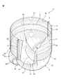
- FIG. 1 is a partially broken perspective view schematically showing an embodiment of a disposable diaper according to the present invention.
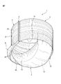
- FIG. 2 is a schematic perspective view of the disposable diaper according to the embodiment of the present invention as viewed from a position different from that in FIG.
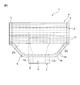
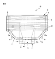
- FIG. 3 is a rear view schematically showing one embodiment of the disposable diaper according to the present invention.
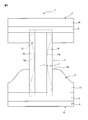
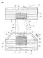
- FIG. 4 is a plan view schematically showing a state where the disposable diaper of FIG. 1 is developed. However, the state seen from the liquid-permeable sheet side of the crotch sheet member is shown.
- FIG. 5 is a diagram schematically showing a state in which the disposable diaper of FIG. 1 is expanded as seen from a direction different from FIG.
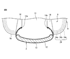
- FIG. 6 is a schematic enlarged cross-sectional view of a main part of the disposable diaper of FIG. 1 cut by a crotch sheet member.
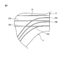
- FIG. 7 is a diagram schematically showing a state in which the first elastic member and the second elastic member in the back seat member intersect each other.
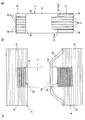
- FIG. 8 schematically shows (a) a state where the second adhesive portion is formed on the ventral sheet member and the back side sheet member, and (b) a state where the first adhesive portion is formed on the crotch sheet member.
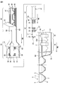
- FIG. FIG. 9 is a diagram for explaining a process for producing a disposable diaper according to the present invention.
- FIG. 10 is a rear view schematically showing another embodiment of the disposable diaper according to the present invention.
- the disposable diaper 1 of this embodiment has three main parts covering the stomach side, the back side, and the crotch part of the wearer. This is a so-called three-piece type made of a substantially rectangular sheet member.
- the disposable diaper 1 includes a crotch sheet member 2 that is long in one direction that covers the wearer's crotch, and the crotch sheet member 2 that overlaps the crotch sheet member 2 on one end side in the length direction of the crotch sheet member 2.
- a ventral sheet member 3 covering the abdomen of the wearer, which is joined in a state where it is applied.
- the back of the wearer is joined to the other end in the longitudinal direction of the crotch sheet member 2 in a state of being overlapped with the crotch sheet member 2.
- a back sheet member 4 covering the side.
- the crotch sheet member 2 and the ventral sheet member 3, and the crotch sheet member 2 and the back sheet member 4 are joined to each other by an adhesive at the portion where they are overlapped.
- the disposable diaper 1 includes a ventral sheet member 3 and a dorsal sheet member 4 in the length direction of the ventral sheet member 3 and the dorsal sheet member 4.
- a so-called underpants type is obtained that is joined to each other by various means such as heat sealing or fusion by ultrasonic sealing.
- the disposable diaper 1 has a waist opening 1a formed by the ventral sheet member 3 and the dorsal seat member 4 on the upper side when worn (standing), and on the lower side, the ventral sheet member 3 and The back sheet member 4 and the crotch sheet member 2 form a pair of leg openings 1b, 1b through which the wearer's leg passes.
- both ends of the crotch sheet member 2 are covered with a joint between the abdomen sheet member 3 and the back sheet member 4 joined to the crotch sheet member 2 to improve the touch.
- seat member 6 formed with the nonwoven fabric excellent in air permeability is each attached.
- the crotch sheet member 2 is formed in a substantially rectangular shape in plan view, extending from the abdominal sheet member 3 through the lower side of the wearer's crotch part toward the back sheet member 4.
- the crotch sheet member 2 has a liquid-permeable liquid-permeable sheet 11 (so-called top sheet) that is located on the skin surface side of the wearer and extends in the length direction of the crotch sheet member 2, and the wearer.
- a liquid-impermeable sheet 12 (so-called back sheet) having liquid-impermeable properties, which is located on the opposite side to the skin surface side and extends in the length direction of the crotch sheet member 2.
- the length of the crotch sheet member 2 that is disposed between the liquid-permeable sheet 11 and the liquid-impermeable sheet 12 and absorbs and holds excretion liquid such as urine excreted from the wearer.
- An absorbent body 13 extending in the lengthwise direction and a pair of leak-proof walls 14 extending in the lengthwise direction of the crotch sheet member 2 along the absorbent body 13 are provided.
- dorsal sheet member 4 are. It is directly joined by an adhesive. Therefore, the said disposable diaper 1 has the structure of a complete 3 piece type disposable diaper among 3 piece type disposable diapers.
- the absorbent body 13 has an absorbent core that substantially absorbs and retains excretory fluid, and a liquid-permeable covering sheet that covers the outer surface of the absorbent core.
- the absorbent body 13 absorbs the absorbent core on both end sides in the width direction so that the absorbent body 13 can easily fit the base of the thigh of the wearer.
- Leg necks 13a, 13a that are curved so as to protrude toward the center of the width direction of the body 13 are formed.
- the liquid-permeable sheet 11 is in contact with the wearer's skin and quickly absorbs the wearer's urine and transfers it to the absorbent body 13 in one direction, specifically the length direction of the absorbent body 13. And is formed in a substantially rectangular shape in plan view that is larger than the absorbent body 13 as a whole, and is joined to the absorbent body 13 by any joining means such as bonding with a hot-melt adhesive. .
- the liquid permeable sheet 11 is formed of a nonwoven fabric, a woven fabric, a synthetic resin film in which liquid permeable holes are formed, a net-like sheet having a mesh, or the like.
- examples of the nonwoven fabric used for the liquid-permeable sheet include natural fibers (for example, cotton), regenerated fibers (for example, rayon), synthetic resin fibers (for example, polyolefin such as polyethylene; polyethylene terephthalate, etc.). Polyester; polyamide such as nylon).
- Non-woven fabrics include core-sheath fibers, side-by-side fibers, island-sea fibers, etc .; hollow fibers, flat fibers, Y-shaped fibers, C-shaped fibers, latent crimps, or actual wrinkles Three-dimensional crimped fibers of shrinkage; split fibers that are split by a physical load such as water flow, heat, embossing, and the like may be mixed.
- the liquid-impermeable sheet 12 prevents permeation of excreted excreted liquid and prevents the excreted liquid from leaking to the outside. Any bonding such as adhesion with a hot-melt adhesive is used. By means, they are joined to the absorber 13.
- the liquid-impermeable sheet 12 is formed in a substantially rectangular shape in plan view that is longer in one direction, specifically in the length direction of the absorber 13 and larger than the absorber 13 as a whole.
- the absorbent body 13 is bonded to each other by any bonding means such as bonding with an adhesive.
- liquid-impermeable sheet for example, a waterproof nonwoven fabric, a synthetic resin (eg, polyethylene, polypropylene, polyethylene terephthalate, etc.) film, a highly water-resistant meltblown nonwoven fabric is sandwiched between strong spunbond nonwoven fabrics An SMS nonwoven fabric or the like can be used.
- a synthetic resin eg, polyethylene, polypropylene, polyethylene terephthalate, etc.
- a highly water-resistant meltblown nonwoven fabric is sandwiched between strong spunbond nonwoven fabrics
- An SMS nonwoven fabric or the like can be used.
- the absorbent core of the absorbent body 13 includes a water absorbent material such as pulp and a highly absorbent material such as a water absorbent polymer, and the lower side of the crotch portion of the wearer from the abdominal sheet member side. It extends long in the direction toward the back side seat member, and is formed in a band shape having a certain thickness.
- the water-absorbing material forming the absorbent core for example, wood pulp obtained from softwood or hardwood (for example, mechanical pulp such as crushed wood pulp; chemical pulp such as kraft pulp; semi-chemical pulp or the like) ); Mercerized pulp or cross-linked pulp obtained by chemically treating wood pulp; Non-wood pulp such as bagasse, kenaf, bamboo, hemp, cotton; Regenerated cellulose such as rayon and fibrillar rayon; Semi-synthetic such as acetate and triacetate Although cellulose etc. are mentioned, a ground pulp is preferable from the point that cost is low and it is easy to shape
- the superabsorbent material examples include starch-based, cellulose-based, and synthetic polymer-based superabsorbent materials.
- starch-based or cellulose-based superabsorbent materials include starch-acrylic acid (salt) graft copolymers, saponified starch-acrylonitrile copolymers, and crosslinked products of sodium carboxymethyl cellulose.
- high water-absorbing materials include polyacrylates, polysulfonates, maleic anhydrides, polyacrylamides, polyvinyl alcohols, polyethylene oxides, polyaspartates, polyglutamates , Polyalginate-based, starch-based, cellulose-based superabsorbent resins (Superabsorbent® Polymer: SAP), etc., among which polyacrylate-based (especially sodium polyacrylate-based) superabsorbent Resins are preferred.
- the shape of the superabsorbent material include particulates, fibers, and scales. In the case of particulates, the particle size is preferably 50 to 1000 ⁇ m, more preferably 100 to 600 ⁇ m. .
- the covering sheet of the absorbent body 13 is not particularly limited as long as it has liquid permeability and absorbent body retainability, but is formed by a wet method using pulverized pulp as a main material from the viewpoint of low cost and absorbent body retainability.
- the tissue to be used is preferred.
- the pair of leak-proof walls 14 and 14 rises toward the skin surface of the wearer when worn, and the tip side comes into contact with the wearer, This is to prevent the excreted liquid from leaking outside between the skin surface of the wearer and the crotch sheet member 2.
- the pair of leak-proof walls 14 and 14 are basically located on the outer side in the width direction of the crotch sheet member 2 with respect to the positions of both end portions in the width direction of the absorber 13, and the absorber
- the absorber 13 extends in the length direction so as to extend along both ends of the width direction of the absorber 13.
- leak-proof walls 14, 14 preferably have hydrophobicity or water repellency so as to prevent leakage of excretory fluid, and may be made of a material such as a spunbond nonwoven fabric, an SMS nonwoven fabric, or an air-through nonwoven fabric. it can.
- elastic members 14a and 14a for leak-proof walls such as thread-like rubber extending in the length direction of the leak-proof walls 14 and 14 are disposed on the upper ends of the leak-proof walls 14 and 14, respectively. Each of the leak-proof walls 14 and 14 is easily adhered to the skin surface of the wearer.
- the abdominal sheet member 3 is formed in a substantially rectangular shape extending long in the direction along the width direction of the crotch sheet member 2, that is, in the left and right direction of the wearer at the time of wearing.
- the length in the length direction is formed larger than the length in the width direction of the crotch sheet member 2.
- the abdomen side sheet member 3 includes an inner surface side sheet 16 positioned on the skin surface side of the wearer and an outer surface positioned on the side opposite to the skin surface of the wearer, that is, on the outer side of the disposable diaper 1.
- a straight line extends in the direction along the width direction of the crotch sheet member 2, that is, in the length direction of the ventral sheet member 3, disposed between the side sheet 17 and the inner surface side sheet 16 and the outer surface side sheet 17.
- a plurality of elastic members 18 extending in the same manner.
- the inner surface side sheet 16 and the outer surface side sheet 17 in the ventral sheet member 3 are formed in the same shape and size from each other by a non-woven fabric having excellent air permeability.
- seat 17 it can form with the nonwoven fabric similar to the liquid-permeable sheet 11 of the said crotch part sheet
- the plurality of elastic members 18 elastically expand and contract in the axial direction, that is, the length direction of the ventral sheet member 3 (the direction along the width direction of the crotch sheet member 2). In the form, rubber formed in a thread shape is used.
- the elastic members 18 are arranged between the inner surface side sheet 16 and the outer surface side sheet 17 in a state of being arranged in the width direction of the abdominal sheet member 3 at a predetermined interval, that is, in the vertical direction when worn. Contained.
- the adhesive agent is apply
- the thickness of the elastic member of the ventral sheet member in the present invention may be, for example, 400 to 1250 dtex, preferably 470, depending on the overall size of the disposable diaper and the size of the ventral sheet member. 940 dtex, more preferably 620 to 780 dtex.
- the elastic member 18 is formed to be thicker than the other elastic members 18 (four in this embodiment) on the side of the waist opening 1a.
- the thick elastic members 18 on the part 1a side are all the same thickness (for example, about 940 dtex), and for the other elastic members 18, the other elastic members 18 are all the same thickness (for example, about 780 dtex). Yes.
- the dorsal seat member 4 like the ventral seat member 3, has a substantially rectangular shape extending long in the direction orthogonal to the length direction of the crotch seat member 2, that is, in the left and right directions of the wearer. It is formed in a shape, and the length in the length direction of the back sheet member 4 is formed larger than the length in the width direction of the crotch sheet member 2.
- the back sheet member 4 includes an inner surface sheet 21 positioned on the skin surface side of the wearer and an outer surface side positioned on the opposite side of the wearer's skin surface, that is, on the outer side of the disposable diaper 1.
- the elastic member is provided.
- the inner surface side sheet 21 and the outer surface side sheet 22 in the back sheet member 4 are formed in the same shape and size from each other by a non-woven fabric having excellent air permeability.
- the inner surface side sheet 21 and the outer surface side sheet 22 are made of the same nonwoven fabric as the liquid permeable sheet 11 of the crotch sheet member 2 and the inner surface side sheet 16 and the outer surface side sheet 17 of the abdominal sheet member 3. Can be formed.
- the plurality of elastic members extend in a direction along the width direction of the crotch sheet member 2 and elastically expand and contract in the length direction. In this embodiment, the rubber formed in a thread shape is respectively used. Used.
- the adhesive agent is apply
- the back sheet member 4 is formed such that the length in the width direction (vertical direction when worn) of the back sheet member 4 is larger than the length in the width direction of the ventral sheet member 3.
- the back sheet member 4 includes a base portion 8 that covers the waist of the wearer and is joined to the ventral sheet member 3, and the length of the crotch sheet member 3 beyond the base portion 8.
- the collar part covering part 9 which is arrange
- the base portion 8 is formed in a substantially rectangular shape that is substantially the same size and shape as the ventral sheet member 3. And in this base
- the first elastic members 23 are positioned in the range of the base portion 8 in the back side seat member 4 in a state where they are arranged in the width direction of the base portion 8 at a predetermined interval, that is, in the vertical direction when worn.
- the inner sheet 21 and the outer sheet 22 are accommodated.
- the same number of the first elastic members 23 are provided at the same intervals as the elastic members 18 of the ventral sheet member 3.
- the thickness of the first elastic member in the present invention may be, for example, 400 to 1250 dtex, preferably 470 to 940 dtex, although it depends on the size of the entire disposable diaper and the size of the back sheet member. More preferably, it is 620 to 780 dtex.
- the first elastic member 23 is formed to be thicker than the other first elastic members 23 in the number of four on the waist opening 1a side (four in this embodiment).
- the thick first elastic members 23 on the side of the waist opening 1a are all the same thickness (for example, about 940 dtex), and the other first elastic members 23 are also the same thickness (for example, 780 dtex). Degree).
- the buttock covering portion 9 has an edge on the center side in the length direction of the crotch sheet member 2 in the width direction of the back side sheet member 4 (vertical direction when worn).
- a portion (hereinafter, simply referred to as an edge portion of the buttock covering portion (9)), that is, a lower end portion when worn is a central side in the length direction of the crotch sheet member 2 (a lower side when worn). It is the structure which protruded so that it might become convex.
- the central portion in the length direction of the back sheet member 4 in the edge portion 9a of the collar covering portion 9, that is, the center in the length direction of the protruding portion is formed.
- the portion is a linear portion extending substantially linearly in the same direction as the length direction of the flange covering portion 9.
- a portion other than the linear portion in the edge portion 9a of the flange covering portion 9 is a curved portion that is gently curved.
- an elastic member other than the first elastic member 23 disposed on the base portion 8 is the collar cover.
- the second elastic member 24 is disposed on the edge portion 9a on the center side in the length direction of the crotch sheet member 2 in the portion 9, that is, on the edge portion on the lower end side when worn.
- the second elastic member 24 extends in the length direction of the back seat member 4 along the edge portion 9a on the center side in the length direction of the crotch seat member 2 in the buttock covering portion 9, and Elastically stretchable in the axial direction.
- the second elastic member 24 as a whole is disposed along the edge portion 9a of the flange covering portion 9, while both end portions are in the length direction of the base portion 8. It has a mode in which it has entered even a part of the region on the side of the flange covering portion 9 on both ends.
- three second elastic members 24 are provided, and these second elastic members 24 are arranged in the width direction of the base portion 8 at regular intervals, that is, in the vertical direction when worn. Are arranged between the inner surface side sheet 21 and the outer surface side sheet 22 positioned in the range of the flange covering portion 9. The thickness of the second elastic member 24 is the same.
- each second elastic member 24 can be 400 to 1250 dtex, for example, preferably 470 to 940 dtex, and more preferably 620 dtex.
- the thickness of the second elastic member 24 is the first elasticity described in detail later in order to cover the buttocks without biting into the buttocks of the wearer and maintaining a comfortable wearing feeling. It is preferable to make the thickness smaller than the thickness of the members 23a and 23b (for example, the thickness of the second elastic member 24 is 620 dtex with respect to the thickness 780 dtex of the first elastic members 23a and 23b).
- the first elastic member 23 and the second elastic member 24 are located on the end side in the length direction of the back seat member 4.
- a part of each axial end portion is fixed to an inner sheet 21 and an outer sheet 22 that form the back sheet member 4 in a state of crossing each other.
- both end portions of the second elastic member 24 are in a state where they enter into a part of the base portion 8 on the side of the flange covering portion 9 as described above.
- the portion of the second elastic member 24 that has entered the base portion intersects with a part of the first elastic member 23 provided on the base portion 8.
- the end portions of the two first elastic members 23a, 23b located on the base portion 8 on the side of the buttock covering portion 9 (the lower side of the base portion 8 when worn), and three pieces A part of the second elastic members 24 a to 24 c on the end side is fixed in a state of intersecting with each other at the joint 5.
- the fact that the first elastic member and the second elastic member intersect each other at the joint portion means that the intersection of the first elastic member and the second elastic member is located at the joint portion.
- each of the first elastic member and the second elastic member It also includes a state in which a part on the end side in the axial direction has reached the nearest joint part while maintaining a state where the parts cross each other.
- the second elastic member 24a located closest to the base portion side has the two end portions in the axial direction at the two ends.
- the first elastic members 23a, 23b of the back side sheet member 4 are crossed at positions close to the joint portion 5 (near the joint portion 5) at both end portions of the back-side sheet member 4, and both end portions remain in the crossed state.
- the second elastic member 24b positioned between the two second elastic members 23a and 23c has both end portions in the axial direction thereof.
- the first elastic member 23b positioned closest to the buttock covering portion of the two first elastic members, and intersecting at the positions near the joint portion 5 at both end portions of the back seat member 4, and While maintaining the crossed state, it reaches the both ends of the back side seat member 4 (base portion 8), that is, the joint portions 5 and 5 without crossing the other first elastic member 23a.
- the second elastic member 24c disposed at the position farthest from the base end portion 8 has both end portions in the axial direction at the most covering portion of the two first elastic members 23, 23.
- the first elastic member 23b located on the side of the portion 9 and the crossed first elastic member 23b are maintained in a state of being intersected at positions near the joint portion 5 at both end portions of the back seat member 4.
- the back sheet member 4 (base portion 8) is configured to extend to both ends of the back side sheet member 4 (base portion 8), that is, the joining portions 5 and 5.
- first elastic member 23 and the second elastic member 24 are part of the respective axial end portions located on the end portions in the length direction of the back seat member 4. Are in a state in which the crotch sheet member 2 is pulled upward to fit the crotch sheet member 2 to the wear site of the wearer.
- the crotch sheet member lifts the disposable diaper due to friction between the wearer's thigh and the edge of the crotch opening of the disposable diaper. Since a force in the direction opposite to the direction acts, the crotch sheet member is easily pulled down by being pulled downward, and may not be easily fitted to the wearing site. In addition, when the absorbent body absorbs and holds excrement such as urine after wearing the disposable diaper, the crotch sheet member tends to hang downward due to the weight of the absorbent body. In this case, the crotch sheet member is less likely to fit the wearer's wearing site.
- dorsal seat member 4 The first elastic member 23 and the second elastic member 24 cooperate to pull up the crotch sheet member upward so that the state can be maintained. Thereby, the fitting feeling of the crotch sheet member 2 at the time of wearing and after wearing can be ensured.
- the back-side sheet member 4 when the back-side sheet member 4 is pulled in the length direction of the back-side sheet member 4 by expanding the waist opening 1a of the disposable diaper 1 when worn, the first elastic member 23 is pulled in the length direction, and the second elastic member 24 (that is, the second elastic member 24 intersecting with the first elastic member 23 (first elastic members 23a and 23b in this embodiment)).
- the elastic members 24a to 24c) are pulled up.
- the buttock covering portion 9 on which the second elastic member 24 is disposed is pulled upward, and the crotch sheet member 2 joined to the buttock covering portion 9 is lifted upward.
- the crotch sheet member 2 rises to the height of the leg opening 1b, 1b, so that the opening direction of the leg opening 1b, 1b approaches the pulling direction of the disposable diaper 1.
- the abdominal sheet member 3 or the back sheet member 4 is pulled.
- the first elastic member 23 or the second elastic member alone is pulled. 24 elastically raises the crotch sheet member 2 upward.
- the second elastic member 24 can pull the crotch sheet member 2 up to the wearer's wear site, the crotch sheet member 2 can be fitted to the wear site.
- the second elastic member 24 is connected to the crotch sheet member through the buttock covering portion 9. 2 is elastically pulled upward. Further, the first elastic member 23 intersecting the second elastic member 24 has a first elastic force that pulls the crotch sheet member 2 acting on the second elastic member 24 downward. The members 23 are dispersed in the axial direction. Accordingly, in order to reduce the load acting on the second elastic member 24, the crotch sheet member 2 is lifted more stably regardless of the weight of the absorbent body 13, and the raised state is stable. As a result, it is possible to ensure a good fit of the crotch sheet member 2 after wearing.
- the first elastic member 23 and the second elastic member 24 intersect at the joint portions 5 and 5, the first elastic members intersect each other.
- 23 and the second elastic member 24 are interlocked with the movements of the ventral sheet member 3 and the dorsal seat member 4 or the movements of both the ventral sheet member 3 and the dorsal seat member 4.
- the second elastic member 24 has a crotch rather than a portion (hereinafter referred to as a first portion) joined to the crotch sheet member 2 in the buttock covering portion 9 of the back sheet member 4.
- the portion not joined to the part sheet member 2 (hereinafter referred to as the second portion) is fixed to the edge portion 9a of the collar covering portion 9 in a contracted state. That is, at the time of manufacturing the disposable diaper 1, a portion of the second elastic member 24 that is located in the second portion of the buttock covering portion 9 is extended as compared with a portion that is located in the first portion.
- the edge part 9a of the collar part covering part 9 and the vicinity thereof contract more in the second part than in the first part. It is in a state of being.
- the 2nd part of the said collar part cover part 9 has a big bending compared with the said 1st part, and is the axis line from the natural length of the 2nd elastic member 24.
- the extension length in the direction is also large.
- the second portion has a strong elastic contraction force due to the elastic force of the portion of the second elastic member 24 located at the second portion. Become.
- the second portion of the buttock covering portion 9 is such that the edge portion 9a of the buttock covering portion 9 extends appropriately according to the size and bulge of the wearer's buttock,
- the portion of the second elastic member 24 positioned at the second portion can be extended longer than the portion of the second elastic member 24 positioned at the first portion. Since the part located in the second part of the elastic member 24 tends to contract with a strong force according to the extension length, the crotch sheet member 2 can be pulled up more effectively.
- the stretchability to the said crotch sheet member 2 is moderately stretched by the expansion-contraction of the part located in this 1st part in the said 2nd elastic member 24.
- the collar cover portion 9 prevents the crotch sheet member 2 from being compressed in the width direction of the crotch sheet member 2 by the elastic force of the second elastic member 24 as much as possible. be able to. Thereby, compression of the said absorber 13 can be suppressed as much as possible, and a fall of an absorptivity and the reduction
- the part located in the 1st part of the said collar part covering part 9 is 1.2 of natural length of this 2nd elastic member 24 at the time of manufacture of the said disposable diaper 1.
- the portion of the second elastic member 24 that is located at the second portion of the collar cover portion 9 is 2.0 times the natural length of the second elastic member 24 when the disposable diaper 1 is manufactured.
- the first portion of the flange covering portion 9 is the curved portion of the edge portion 9a of the flange covering portion
- the second portion is the straight portion of the edge portion 9a of the flange covering portion 9.
- the first adhesive portions 26 and 27 are respectively disposed on the center side in the width direction of the liquid-impermeable sheet 12 in the crotch sheet member 2. ing.
- the first adhesive portions 26 and 27 are provided with first adhesive application regions 30 and 31 that are continuous in the length direction of the liquid-impermeable sheet 12, respectively.
- the first adhesive application region 30 is formed on the first adhesive portion 26 formed on the end side joined to the ventral sheet member 3, and the end portion joined to the ventral sheet member 3.
- a first adhesive application region 31 is provided in each of the first adhesive portions 26 formed on the side.
- the crotch sheet member 2 is formed on the inner side sheet member 16 of the ventral sheet member 3 and the back sheet member 4 on the center side in the width direction where the first adhesive portions 26 and 27 are provided. 21 respectively. At this time, there are regions where the first adhesive portions 26 and 27 do not exist on both end sides in the width direction of the liquid-impermeable sheet 12. Further, the first adhesive portions 26, 27 do not exist on the pair of leak-proof walls 14, 14 in the crotch sheet member 2.
- the liquid impervious sheet 12 extends to the center side in the length direction until it overlaps with a portion where the second elastic member 24 of the collar covering portion 9 is located.
- the crotch sheet member 2 and the portion of the buttock covering portion 9 of the back sheet member 4 where the second elastic member is positioned are joined to each other through the first adhesive portion 27. It becomes.
- the liquid impervious sheet 12 is configured to extend to the center side in the longitudinal direction up to a position overlapping the portion where the elastic member 24 is located is as follows. That is, when the disposable diaper 1 is worn or when the absorbent body 13 becomes heavy due to absorption and retention of excrement, the crotch sheet member 2 hangs down and the crotch sheet member 2 This is to suppress as much as possible the difficulty of fitting to the wearing site.
- the diaper is absorbed and retained by friction between the thigh of the wearer and the edge of the leg opening 1b, 1b of the disposable diaper 1 or when the disposable diaper is worn. Since the crotch sheet member 2 tends to hang downward due to the weight of the absorbent body 13, the crotch sheet member 2 may not easily fit the wearer's wearing site. Therefore, a part of the first adhesive portion 27 is extended to a position overlapping the portion where the second elastic member 24 of the flange covering portion 9 is located, and the second elastic member 24 in the flange covering portion 9 is arranged. The installed position and the crotch sheet member 4 can be joined, and the downward force acting on the crotch sheet member 9 is reliably transmitted to the second elastic member 24.
- the crotch sheet member 2 is stably lifted upward by the elastic force of the second elastic member 24, so that the crotch sheet member 2 is worn when and after the disposable diaper 1 is worn. It can be made to fit stably by a person's wearing part.
- the first adhesive application regions 30 and 31 have an adhesive from the position on the end side closest to the length direction of the liquid-impermeable sheet 12, The liquid-impermeable sheet 12 is applied toward the position on the center side in the length direction.
- the first adhesive portion 26 is used.
- 27 is a mode in which a plurality of the first adhesive application regions 30, 31 are provided in a state of being arranged in the width direction of the liquid-impermeable sheet 12. Further, as shown in FIG.
- the first adhesive application area 31 of the first adhesive part 27 is arranged on the first adhesive part 27 provided on the end part side to be joined to the back sheet member 4.
- the first adhesive application areas 31 a and 31 a located on both end sides in the width direction of the crotch sheet member 2 are compared to the other first adhesive application areas 31.
- the length in the length direction is shortened.
- the length in the length direction of the crotch sheet member 2 of the first adhesive application regions 31a and 31a located on both ends in the width direction of the crotch sheet member 2 is the back sheet.
- the length of the second adhesive portion 29 provided on the member 4 in the width direction of the back sheet member 4 is substantially the same.
- the first adhesive application region 31 other than the first adhesive application regions 31a, 31a located on both end sides in the width direction of the crotch sheet member 2 is the second elastic member of the buttock covering portion 9
- the liquid impervious sheet 12 extends to the center side in the length direction up to a position where it overlaps with a portion where 24 is located.
- the reason why the first adhesive portions 26 and 27 are provided on the liquid-impermeable sheet 12 of the crotch sheet member 2 is to efficiently apply the adhesive to the liquid-impermeable sheet 12. This is because the process is performed stably.
- the crotch sheet member is conveyed in the length direction of the crotch sheet member up to a predetermined position before being joined to the abdominal sheet member or the back sheet member. The Therefore, the application of the adhesive to the liquid-impermeable sheet during the conveyance of the crotch sheet member is most efficient when applied along the length direction that is the conveyance direction of the crotch sheet member, In addition, since the application itself is easy and there are few failures, the application can be performed stably.
- any adhesive can be used as the adhesive applied to the first adhesive application areas 30 and 31, but a hot-melt adhesive is most preferable.
- the hot melt adhesive include polyolefin (for example, polyethylene and polypropylene), ethylene / vinyl acetate copolymer system, synthetic rubber (for example, styrene / isoprene / styrene (SIS), styrene / butadiene / styrene (SBS)). ), Styrene-based polymers such as styrene-ethylene-butylene-styrene (SEBS), butadiene-based polymers, isoprene-based polymers).
- SEBS styrene-ethylene-butylene-styrene
- an acrylic resin-based pressure-sensitive adhesive can be used as other adhesives.
- any pattern can be used as an application pattern of the adhesive applied to the first adhesive application regions 30 and 31, any pattern can be used.
- a spiral shape, an omega ( ⁇ ) shape, a broken line, a curve, Any coating pattern such as a straight (bead) shape or a strip shape wider than the linear coating pattern can be used.
- the adhesive application pattern if the first adhesive application regions 30, 31 themselves are considered to be continuous in the length direction of the crotch sheet member 2, the adhesive is the first. It is not necessary that the coating pattern be continuously applied in the adhesive application regions 30 and 31. That is, for example, in the first adhesive application areas 30 and 31, the adhesive is intermittently applied in the form of dots (dots) or broken lines in the length direction of the crotch sheet member 2. It may be.
- a method of applying the adhesive a method of applying an adhesive by spraying an adhesive from a single or a plurality of nozzles to apply various linear or dotted application patterns, a roll or the like to the application target site.
- Any coating method can be used such as a method in which the adhesive is contacted to apply a surface or a dot pattern of a surface, or a method in which the adhesive is sprayed and applied from a nozzle.
- each adhesive applied in each first adhesive application region 30, 31 is the total number or length of the first adhesive application regions 30, 31 in the first adhesive portions 26, 27, It can be appropriately selected depending on the application pattern of the adhesive.
- the application amount of the adhesive in each first adhesive application region in the present invention is preferably 2 to 25 g / m 2 , more preferably 4 to 22 g / m 2 , more preferably 5 to 19 g / m 2. It is to be about. 2 g / When m is less than 2, the bonding is unsuccessful and the second adhesive portion adhesive force is insufficient, also may come off easily pull becomes 25 g / m 2 than the opposite of each sheet member 2 ⁇ 4 may be hardened by the adhesive 29 and may be stiff.
- the plurality of first adhesive application regions 30, 31 are the same among the first adhesive application regions 30, 31.
- the first adhesive application areas 30 and 31 located on both ends in the width direction of the liquid-impermeable sheet 12 in the crotch sheet member 2 are adjacent to the other adjacent first adhesive application areas 30 and 31.
- the gaps 39 and 40 are provided between them, respectively.
- the crotch sheet member 2 (more specifically, the liquid-impermeable sheet 12) is pulled away from the abdominal sheet member 3 and the back sheet member 4 in the first adhesive application regions 30 and 31. , It is possible to deter the dropout.
- the second adhesive portions 28 and 29 are provided on the inner surface side sheet 16 of the ventral sheet member 3 and the inner surface side sheet 21 of the back side sheet member 4.
- the crotch sheet member 2 is provided at a position where the crotch sheet member 2 comes into contact with the liquid-impermeable sheet 12, more specifically, at a position where the crotch sheet member 2 overlaps the first adhesive portions 26 and 27 provided on the liquid-impermeable sheet 12.
- the second adhesive portion 28 provided on the ventral sheet member 3 has a second continuous portion in the width direction of the crotch sheet member 2, that is, in the length direction of the ventral sheet member 3. Two adhesive application areas 33 are provided.
- the second adhesive portion 29 provided on the back sheet member has a second continuous portion in the width direction of the crotch sheet member 2, that is, in the length direction of the back sheet member 4.
- An adhesive application region 34 is provided.
- the second adhesive portions 28 and 29 have the second adhesive application regions 33 and 34 in the length direction of the crotch sheet member 2, that is, the ventral sheet member 3 and It is the aspect provided with two or more in the state located in a line with each width direction of the back
- the lengths of the second adhesive portions 28 and 29, that is, the lengths of the abdominal sheet member 3 and the back sheet member 4 in the length direction are the second lengths.
- the width of the first adhesive portions 26 and 27 joined to the adhesive portions 28 and 29, that is, the length in the width direction of the crotch sheet member 2 in the first adhesive portions 26 and 27 is formed to be approximately the same length.
- these 2nd adhesion parts 28 and 29 and the 1st adhesion parts 26 and 27 are the position of the both ends of the length direction in these 2nd adhesion parts 28 and 29, and this 1st adhesion part. It joins in the state which the position of the both ends of the width direction in 26 and 27 substantially corresponded mutually.
- the crotch sheet member 2 has the width direction of the ventral sheet member 3 and only in the region where both the first adhesive portions 26 and 27 and the second adhesive portions 28 and 29 exist. Joining with the back seat member 4 is performed. At this time, as described above, since there is a region where the first adhesive portions 26 and 27 do not exist on both end sides in the width direction of the liquid impermeable sheet 12, the crotch sheet member 2 includes: The crotch sheet member 2 is not joined to the abdomen sheet member 3 and the dorsal sheet member 4 at both end portions in the width direction of the crotch sheet member 2 in the portion overlapped with the ventral sheet member 3 and the dorsal sheet member 4. Non-joining regions 36, 36, 37, and 37 are formed, respectively.
- the non-joining regions 36, 36, 37, and 37 are located on the inner side (the center in the width direction) of the crotch sheet member 2 in the non-joining regions 36, 36, 37, and 37. Further, it extends to the portion corresponding to the position entering the inner side in the width direction of the absorber 13 (the center side in the width direction) rather than the both end portions in the width direction of the absorber 13. That is, the non-joining regions 36 and 36 are provided between the liquid-impermeable sheet 12 and the ventral sheet member 3 of the crotch sheet member 2, and the non-joining regions 37 and 37 are provided on the crotch sheet member 2. Between the liquid-impermeable sheet 12 and the back sheet member 4, it is formed so as to enter the inner side in the width direction of the absorber 13 with respect to the positions on both ends in the width direction of the absorber 13. .
- the non-joining regions 36, 36, 37, and 37 are provided so that the absorber 13 is free without being restricted by the presence or movement of the ventral seat member 3 and the back seat member 4. This is because it can be easily stretched and deformed to easily fit the wearer's skin, and the volume of the absorbent body 13 and the area of the liquid-permeable sheet 11 that receives the excrement are widened.
- the second elastic member 24 exerts a force that the buttock covering portion 9 elastically contracts in the width direction.
- a force that compresses in the width direction acts on the absorber 13 through the flange covering portion 9.
- size of the said absorber 13 will become small and not only the area at the side of the liquid-permeable sheet 11 which receives excrement will become small, but the volume may become small and an absorptivity may be impaired. Since the free deformation and expansion / contraction of the absorbent body 13 are restricted, it is difficult to fit the wearer's skin. Therefore, the non-joining regions 36, 36, 37, 37 are provided so that the absorber 13 can be contracted and deformed relatively easily without being restrained by the abdominal sheet member 3 and the back sheet member 4. ing.
- the second adhesive portions 28 and 29 do not contact the pair of leak-proof walls 14 and 14.
- the leak-proof walls 14 and 14 themselves are basically not joined to the abdominal sheet member 3 and the base portion 8 and the buttock covering portion 9 of the back-side sheet member 4. Thereby, the pair of leak-proof walls 14 and 14 are not affected by the movement of the base portion 8 and the buttock covering member 9 of the abdominal side sheet member 3 and further the back side sheet member 4 when worn. It is possible to stably maintain the state in which the distal end side rises upward, and it is possible to reliably fit the distal end side of each leakage prevention wall 14, 14 to the wearer's skin.
- the deformation / extension of the absorber 13 is relatively free without being constrained by the ventral seat member 3 and the back seat member 4, As shown in FIG. 6, the end portions of the absorbent body 13 in the width direction are easily curved along the rising direction of the pair of leak-proof walls 14 and 14, thereby allowing the excrement to flow outward. It becomes possible to prevent leakage more reliably.
- the back side seat member 4 side of the crotch seat member 2 in general, when the wearer lies on his back, excrement can easily leak out from the leg openings 1b and 1b. It is effective because of its characteristics.
- the crotch sheet member when the entire absorbent body 13 is worn is provided by providing the non-joining regions 36, 36, 37, and 37 so as to stably maintain the state in which the pair of leak-proof walls 14 and 14 are raised.
- both ends in the width direction are curved along the rising direction of the leakage prevention walls 14, 14, so that excrement can be efficiently absorbed and leakage is effectively performed. Can be prevented.
- the second adhesive application areas 33 and 34 are the first adhesive of the crotch sheet member 2 in the second adhesive portions 28 and 29.
- the adhesive 26 is applied so as to extend from a position corresponding to one end in the width direction toward a position corresponding to the other end.
- second adhesive application regions 33 and 34 are arranged in the second adhesive portions 28 and 29 in the width direction of the ventral sheet member 3 and the back sheet member 4, respectively. In this state, a plurality are provided.
- each second adhesive application region 33, 34 itself is spaced from another adjacent second adhesive application region 33, 34. Instead, they are arranged in contact with each other. In this case, the adhesive applied to each of the second adhesive application regions 33 and 34 is in contact with or overlapped with the adhesive applied to the other adjacent second adhesive application regions 33 and 34. There is a part that has been made, and the adhesive is integrated into that part. However, even if the second adhesive application areas 33 and 34 are in contact with each other or overlap, the adhesives may not be in contact with each other or may not overlap depending on the application pattern, but the adhesives are not necessarily in contact with each other or overlap each other. Since it is not necessary, an appropriate application pattern can be freely selected.
- the second adhesive portions 28 and 29 are provided on the ventral sheet member 3 and the dorsal sheet member 4, respectively, because the adhesive is applied to the ventral sheet member 3 and the dorsal sheet member 4. It is for performing application
- the abdominal sheet member and the back sheet member are conveyed in the length direction of the abdomen sheet member and the back sheet member to a predetermined position. Therefore, the application of the adhesive during the conveyance of the abdominal sheet member and the back sheet member is performed along the length direction which is the conveyance direction of these abdominal sheet member and the back sheet member. Since it is the most efficient, the application itself is easy to perform, and there are few failures, it is possible to perform the application stably.
- the adhesive applied to the second adhesive application areas 33, 34 it is preferable to basically use the same adhesive as that used in the first adhesive application areas 30, 31.
- a hot melt adhesive is most preferable.
- the material of the hot melt adhesive is the same as that in the first adhesive application areas 30 and 31.
- the adhesive application pattern applied to the second adhesive application areas 33 and 34 is basically the same as the adhesive application pattern in the first adhesive application areas 30 and 31. However, it may be a different coating pattern.
- the type and application method of the adhesive application pattern applied to the second adhesive application areas 33 and 34 are basically the same as those of the first adhesive application area. Omitted.
- the amount of each adhesive applied in each of the second adhesive application regions 33 and 34 is the total number, length, and length of the second adhesive application regions 33 and 34 in the second adhesive portions 28 and 29. It is set according to the application pattern of the adhesive.
- the application amount of the adhesive in each second adhesive application region is preferably 2 to 25 g / m 2 , more preferably 4 to 22 g / m 2 , more preferably about 5 to 19 g / m 2 . That is. If less than 2 g / m 2, junction unsuccessful the first adhesive portion 26 adhesion is insufficient, and may peel off easily pull becomes 25 g / m 2 than the opposite of each sheet member 2 to 4 are hardened by the adhesive and may be stiff.
- the crotch sheet member 2 (more specifically, the liquid-impermeable sheet 12) and the ventral sheet member 3, and the crotch sheet member 2 (more specifically, the liquid-impermeable sheet 12) and the back-side sheet.
- the member 4 intersects the first adhesive application regions 30 and 31 in the first adhesive portions 26 and 27 and the second adhesive application regions 33 and 34 in the second adhesive portions 28 and 29. In this state, they are joined to each other. Therefore, the first adhesive is applied in a state where the adhesive applied to the first adhesive application areas 30 and 31 and the adhesive applied to the second adhesive application areas 33 and 34 also intersect each other.
- the adhesive application regions 30 and 31 are in contact with the second adhesive portions 28 and 29, and the second adhesive application regions 33 and 34 are in contact with the first adhesive portions 26 and 27, respectively.
- the Rukoto is the first adhesive application regions 30 and 31 in contact with the second adhesive portions 28 and 29, and the second adhesive application regions 33 and 34 are in contact with the first adhesive portions 26 and 27, respectively.
- the first adhesive application areas 30 and 31 in the first adhesive portions 26 and 27 intersect with the second adhesive application areas 33 and 34 in the second adhesive portions 28 and 29.
- the crotch sheet member 2 and the abdominal sheet member 3 and the back sheet member 4 are joined together so that the crotch sheet member 2 that has become heavy due to the excrement fluid of the wearer is held firmly. It is to do. Furthermore, this is to prevent the crotch sheet member 2 from being separated from the ventral sheet member 3 and the back sheet member 4 due to its weight and falling off. That is, as already described, when the disposable diaper excretes excretory fluid such as urine from the wearer, the disposable diaper absorbs and holds the excreted fluid by the absorber provided in the crotch sheet member.
- the crotch sheet member becomes heavy, and the crotch sheet member is pulled downward by the weight. Therefore, the crotch sheet member 2 is pulled up by the first adhesive application regions 30 and 31 continuous in the length direction of the crotch sheet member 2 so as not to sag as much as possible. .
- the second adhesive application areas 33 and 34 intersecting with the first adhesive application areas 30 and 31 a downward tensile force acting on the first adhesive application areas 30 and 31 is applied to the crotch.
- the sheet member 2 is dispersed in the width direction. As a result, the first adhesive application region and the second adhesive application region cooperate to make it difficult for the crotch sheet member to hang down and stably maintain the pulled-up state.
- the abdominal sheet member 3 and the back sheet member 4 are at least a part of the plurality of elastic members 18 disposed on the abdominal sheet member 3,
- at least a part of the plurality of first elastic members 23 disposed on the base portion 8 of the back seat member 4 is disposed at a position corresponding to the second bonding portions 28 and 29.
- the elastic member 18 and the first elastic member 23 disposed on the base portion 8 of the back side sheet member 4 it can be dispersed in the length direction of the abdominal side sheet member 3 and the back side sheet member 4. Therefore, the crotch sheet member 2 is less likely to hang down, and the pulled-up state can be more stably maintained.
- a step S1 of forming a laminate for the crotch sheet member, a composite member for a ventral sheet member, and a composite member for a back sheet member Step S2 of forming is performed as a preparation step.
- step S3 of forming the crotch sheet member and the first adhesive portion from the laminate for the crotch sheet member, and the second member in the composite member for the abdominal sheet member and the composite member for the back sheet member The process S4 which forms the adhesion part, and the process S5 for joining the crotch sheet member, the composite member for the abdomen sheet member, and the composite member for the back sheet member are performed. Further, a step S6 is performed in which the composite member for the back side sheet member is cut (leg cut) in accordance with a predetermined shape of the buttock covering portion in the back side sheet member 4 of the disposable diaper 1.
- the cutting step S8 is performed.
- step S1 for forming the laminate for the crotch sheet member and step S2 for forming a composite member for the abdomen sheet member and a composite member for the back sheet member are performed as a preparatory step.
- the step S1 for forming the laminate for the crotch sheet member will be described. That is, in this step S1, a liquid-permeable sheet, a liquid-impermeable sheet, an absorber, and a pair of leak-proof walls constituting the crotch sheet member 2 are laminated. And the long laminated body 41 for crotch sheet members is formed in the conveying direction (however, the liquid-permeable sheet, the liquid-impermeable sheet, and the pair of leak-proof walls are long formed in the conveying direction. ).
- the laminate 41 for the crotch sheet member is transported toward the next step S3 in which the crotch sheet member 2 and the first adhesive portions 26 and 27 are formed.
- the laminate 41 for the crotch sheet member is in a state before the individual crotch sheet members 2 are formed, in which a plurality of crotch sheet members 2 are substantially continuous in the length direction. Individual crotch sheet members 2 are obtained by cutting into a predetermined length in the process.
- step S2 of forming a composite member for the abdominal sheet member and the back sheet member will be described.
- This process S2 is carrying out the nonwoven fabric 46 for the outer surface side sheet
- a plurality of long elastic members 47 to 49 extend in the length direction of the nonwoven fabric 46 for the outer surface side sheet, and expand and contract in the length direction (axial direction) from the natural length to a predetermined magnification. Is disposed.
- the plurality of long elastic members 48 and 49 for the back-side seat member are arranged at predetermined intervals.
- the plurality of long elastic members 47 to 49 are arranged in a state where the axial direction of the long elastic members 47 to 49 is directed to the length direction of the nonwoven fabric 46 for the outer sheet. Is done.
- the abdomen sheet member composite member 50 forms the abdomen sheet member 3 in the finished disposable diaper 1, and the back sheet member composite member 51 is the disposable diaper 1.
- the back seat member 4 is formed.
- the elastic members 48 and 49 for the back-side sheet member are for the first back-side sheet member disposed at a position corresponding to the base portion 8 in the back-side sheet member 4 in the disposable diaper 1.
- the elastic member 48 and the second elastic member 49 for the back-side sheet member disposed at a position corresponding to the buttock covering portion 9 are different in the disposition method for the nonwoven fabric 46 for the outer surface-side sheet.
- the said 1st elastic member 48 for back side seat members becomes the 1st elastic member 23 provided in the back side seat member 4 in the said disposable diaper 1 as a finished product,
- the elastic member 49 is a second elastic member provided on the back sheet member 4 of the disposable diaper 1.
- the outer surface side non-woven fabric 46 is arranged in a substantially straight line.
- the second elastic member 49 for the back side seat member is convex toward the shape of the predetermined edge portion 9a of the buttock covering portion 9, that is, the central side in the length direction of the crotch seat member. It arrange
- the central portion in the width direction of the back sheet member at the edge portion 9a of the collar cover portion 9 is substantially straight in the same direction as the length direction of the collar cover portion. It becomes the linear part extended in the shape. Therefore, about the part of the elastic member 49 for 2nd back side sheet members located in this linear part, the axial direction is arrange
- the portion located in the linear portion has a natural length of about 1 per unit length of the elastic member 49 for the second back side seat member.
- the outer surface side in a state where the natural length per unit length is approximately doubled. It is preferable to arrange on the nonwoven fabric 46 for sheets substantially linearly.
- the first dorsal sheet member elastic members 48 in the first dorsal sheet member elastic member 48 on the side of the collar covering portion 9 is used.
- the member 48 and the second elastic member 49 for the back sheet member are arranged in the length direction of the back sheet member 4 of the disposable diaper 1 as a finished product on the nonwoven fabric 46 for the outer sheet. It arrange
- the disposable diaper 1 as a finished product has both ends in the axial direction of the first elastic member 23 and the second elastic member 24 at both ends in the length direction of the back sheet member 4. A state in which the part sides cross each other is formed.
- the ventral sheet member 3 and a long non-woven fabric 52 for inner surface side sheets forming the inner surface side sheets 16 and 21 of the back side sheet member 4 are laminated to form a long composite member 53 extending in the conveying direction.
- the composite member 53 is a combination of the composite member 50 for the ventral sheet member and the composite member 51 for the back seat member.
- this composite member 53 is cut
- a long composite member 50 for the abdomen seat member and a long composite member 51 for the back seat member are formed before being divided into the side seat member 3 and the back seat member 4, respectively.
- the abdominal sheet member composite member 50 and the back sheet member composite member 51 include the abdomen sheet member 3 and the back sheet member 4 of the disposable diaper 1 as a finished product. It is in a state of being connected in plural, and is divided into individual abdominal sheet members 3 and back sheet members 4 in a subsequent process.
- the conveyance direction MD of the composite member 50 for the ventral sheet member and the composite member 51 for the back seat member is the length direction of each of the ventral sheet member 3 and the back seat member 4.
- the second adhesive portion which is the next process, is formed while maintaining the state where the abdomen-side sheet member composite member 50 and the back-side sheet member composite member 51 are arranged at a constant interval. It conveys toward process S4.
- step S3 of forming the crotch sheet member 2 and the first adhesive portions 26 and 27 from the laminate 41 for the crotch sheet member is performed.
- the first adhesive portions 26 and 27 are formed by applying various adhesives such as a hot melt adhesive to the liquid-impermeable sheet in the laminate 41 for the crotch sheet member that has been conveyed.
- the length of the crotch sheet member 2 in the longitudinal direction is determined with respect to the laminate 41 for the crotch sheet member.
- An adhesive is applied to the portions corresponding to both end portions of the liquid-impermeable sheet 12 in the crotch sheet member 2 and in contact with the abdomen-side sheet member 3 and the back-side sheet member 4. . Then, first adhesive application regions 30 and 31 that are continuous in the length direction of the liquid-impermeable sheet 12 in the crotch sheet member 2 are provided.
- the laminate 41 for the crotch sheet member is transported in a state where the liquid-impermeable sheet side is positioned on the upper surface for the convenience of manufacturing. It is applied from the upper side of the laminate 41 for the crotch sheet member.
- the laminate 41 for the crotch sheet member is later cut into individual crotch sheet members 2, but in this embodiment, when the adhesive is applied, the laminate 41 is in the conveying direction MD.
- the adhesive is simultaneously applied to form the first adhesive portions 26 and 27 of the crotch sheet members 2 and 2.
- the adhesive is applied to the laminate 41 for the crotch sheet member by applying the adhesive at regular intervals in consideration of a predetermined length in the length direction of the crotch sheet member 2.
- the first adhesive application region 31 over both the tail end side of the portion corresponding to the preceding crotch sheet member 2 and the position on the tip end side of the portion corresponding to the adjacent subsequent crotch sheet member 2, 30 to the first adhesive portions 27 and 26 (in the case of FIG. 9, the first adhesive portion 27 on the tail end side of the portion corresponding to the preceding crotch sheet member 2 and the subsequent crotch sheet member 2
- the first adhesive portion 26 is simultaneously formed on the tip side of the corresponding portion.
- the first adhesive application regions 30 and 31 are arranged in the width direction of the laminate 41 for the crotch sheet member.
- a plurality are provided in the state.
- the first adhesive application regions 30 and 31 are formed in the length direction of the crotch sheet member laminate 41, that is, in the length direction of the portion corresponding to the crotch sheet member 2.
- the first adhesive application regions 30 and 31 positioned on both end sides in the width direction of the laminate 41 for the crotch sheet member are adjacent to each other. It arrange
- the gap 39 between the first adhesive application regions 30, 31 located on both end sides in the width direction of the crotch sheet member 2 is adjacent to the other adjacent first adhesive application regions 30, 31. , 40 are provided, respectively.
- the adhesive material, the application pattern, and the application method of the first adhesive application regions 30 and 31 are arbitrarily selected as described above. can do.
- the application method for example, as shown in FIG. 9, a crotch part being conveyed using an adhesive application device 56 in which a plurality of nozzles (not shown) are arranged in the width direction of the crotch sheet member.
- a plurality of first adhesive application regions 30 and 31 having a predetermined application pattern can be simultaneously formed on the upper surface of the laminate 41 for sheet members, that is, the surface on the liquid-impermeable sheet side. Further, it is not always necessary to form the gaps 39 and 40 between the other adjacent first adhesive application regions 30 and 31. In this case, the other adjacent first adhesive application regions 30 are not necessarily formed.
- 31 are arranged adjacent to or in contact with each other, the first adhesive application areas 30, 31 are arranged.
- the laminated body 41 for said crotch sheet members is cut
- the first adhesive portions 26 and 27 are formed on both ends of the crotch sheet member 2, respectively.
- the composite member 50 for the ventral sheet member and the composite member 51 for the back seat member are formed after the step S2 of forming the composite members 50 and 51 for the ventral sheet member and the back seat member.
- Step S4 for forming the second adhesive portions 28 and 29 is performed.
- hot melt adhesive or the like is applied to the upper surface of the composite member 50 for the stomach side sheet member and the composite member 51 for the back side sheet member that has been conveyed, that is, the nonwoven fabric 52 for the inner surface side sheet.
- the second adhesive portions 28 and 29 are formed by applying the various adhesives. In forming the second adhesive portions 28 and 29, the individual abdominal sheet member 3 and the back sheet member are separated from the composite member 50 for the ventral sheet member and the composite member 51 for the back sheet member.
- second adhesive application regions 33 and 34 that are continuous in the length direction (that is, the conveying direction) of the composite member 50 for the ventral sheet member and the composite member 51 for the back sheet member are provided.
- the plurality of nozzles are provided for the composite member 50 for the abdomen seat member and the composite member 51 for the back seat member.
- a plurality of second adhesive application regions 33 and 34 are simultaneously formed by applying the adhesive in a predetermined application pattern by the adhesive application devices 57 and 58 arranged in the width direction.
- step S5 of joining the crotch sheet member, the composite member for the abdomen seat member, and the composite member for the back seat member is performed.
- step S5 the first adhesive portion 26, the composite member 50 for the abdomen sheet member and the composite member 51 for the back sheet member in which the second adhesive portions 28, 29 are formed, respectively.
- the crotch sheet member 2 formed with 27 both end portions of the liquid-impermeable sheet 12 are brought into contact with each other, and the first adhesive portions 26, 27 and the second adhesive portions 28, 29 are brought into close contact with each other.
- the composite member 50 for the abdominal seat member and the composite member 51 for the back seat member are conveyed in a state where a certain distance is maintained, and the crotch seat member 2 is in the length direction thereof.
- they are disposed along the composite member 50 for the abdominal seat member and the composite member 51 for the back seat member, and in a direction substantially orthogonal to the length direction of both the composite members 50 and 51.
- the first adhesive application areas 30 and 31 and the second adhesive application areas 33 and 34 are in close contact with each other, and the adhesives in the first adhesive application areas 30 and 31
- the adhesives in the second adhesive application areas 33 and 34 are integrated and joined to each other.
- the crotch sheet member 2 is conveyed with the liquid-impermeable sheet 12 on which the first adhesive portions 26 and 27 are formed positioned on the upper surface side.
- the crotch sheet member 2 needs to be brought into contact with the composite member 50 for the abdomen-side sheet member and the composite member 51 for the back-side sheet member after being turned upside down.
- these crotch sheet members 2 and the composite member 50 for the abdomen seat member and the composite member 51 for the back seat member are preferably brought into pressure contact with each other with an appropriate force, whereby the adhesive in the first adhesive application regions 30 and 31 and the first The integration of the adhesives in the adhesive application areas 33 and 34 of No. 2 progresses, and the mutual bonding becomes stronger.
- a step S6 of cutting the composite member for the back sheet member in accordance with a predetermined shape of the buttock covering portion is performed.
- This step S6 is convex toward the shape of the predetermined edge portion 9a of the butt covering portion 9 in the disposable diaper 1 as a product, that is, the central side in the length direction of the crotch sheet member 2.
- a portion corresponding to the edge portion 9a of the buttock covering portion 9 in the composite member 51 for the back seat member is cut (leg cut) so as to conform to the protruding shape.
- the cut in this process S6 is performed so that the said 2nd elastic member 49 for back
- the crotch sheet member 2 is bent to join the crotch sheet member 2 to each other.
- the compound member 50 for the ventral sheet member and the compound member 51 for the back sheet member are overlapped with each other.
- the process S8 which adhere
- the overlapped composite member 50 for the abdominal sheet member and the composite member 51 for the back side sheet member are set to a predetermined length in the length direction of the abdominal side sheet member 3 and the back side sheet member 4.
- bonding is performed at a constant width by any means such as heat sealing or fusion by ultrasonic sealing, with a certain interval. Thereby, the both ends of the length direction of the abdominal sheet member 3 and the back
- a part of this joined part becomes the junction part 5 of each disposable diaper 1 as a finished product.
- a part of the portion where the first back-side seat member elastic member 48 and the second back-side seat member elastic member 49 intersect is a joint between the ventral-side seat member 3 and the back-side seat member 4. It is preferable that it is located in the part and its vicinity.
- the first elastic member 23 of the base portion 8 of the back-side sheet member 4 and the edge of the collar covering portion 9 are used.
- the crotch sheet member 2 is pulled upward. As a result, even if a downward force acts on the crotch sheet member 2 due to friction between the wearer's thigh and the edge portions of the leg opening 1b, 1b, the crotch sheet member 2 can be fitted by firmly pulling up to the wear site of the wearer.
- the disposable diaper 1 is a complete three-piece type, and no frill is formed by an auxiliary sheet that is obstructive when worn like the incomplete three-piece type. There is no such thing that the wearer can wear the disposable diaper stably.
- the second elastic member 24 is not removed through the buttock covering portion 9.
- the crotch sheet member 2 is pulled upward.
- the first elastic member 23 intersecting the second elastic member 24 applies a downward force acting on the second elastic member 24 in the axial direction of the first elastic member 23.
- the crotch sheet member 2 can be pulled up more stably and the state can be maintained. As a result, not only when the disposable diaper 1 is worn, but also after wearing, the state in which the crotch sheet member 2 is fitted to the wearer can be stably maintained, so that the feeling of use can be kept good. It becomes possible.
- the collar cover portion 9 is provided with three second elastic members 24 (24a to 24c) that extend continuously over the entire length of the collar cover portion 9 in the length direction. It has become. However, as shown in FIG. 10, it is good also as a structure which has the discontinuous part in which the 2nd elastic member is discontinuous in a part of the part in which the said absorber is located in the said crotch sheet
- Each of these second elastic members 61 extends from the left and right end portions of the back seat member 2 toward the center in the length direction of the buttock covering portion 9, and The crotch sheet member 2 is in a mode that reaches a position corresponding to a portion where the absorber 13 is located. At this time, the three second elastic members 61 located on the left side and the three second elastic members 61 located on the right side are not in contact with each other. Thereby, the area
- the disposable diaper 60 shown in FIG. 10 is the same as the embodiment described above except for the second elastic member 61, and therefore, the same reference numerals are given and detailed description thereof is omitted.
- the second elastic member 61 is discontinuous in a part of the crotch sheet member 2 where the absorber 13 is located in the buttock covering portion 9 of the back sheet member 4.
- the crotch sheet member 2 is more reliably suppressed from being compressed in the width direction of the crotch sheet member 2 by the elastic force of the second elastic member 61. It is done.
- the compression of the absorbent body 13 is further suppressed, the decrease in the absorption performance of the absorbent body 13 due to the compression and the decrease in the excretion receiving area on the liquid-permeable sheet side of the absorbent body 13 are stably suppressed. be able to.
- the base portion 8 of the back seat member 4 is provided with a plurality of the first elastic members 23. At least one first elastic member is provided. Any number can be provided. Further, as in the above-described embodiment, the number of elastic members 18 provided on the ventral sheet member 3 is not necessarily the same. Further, in the embodiment, the second covering member 9 is provided with three second elastic members 24 (24a to 24c), and at least one second elastic member is provided. 2 or 4 or more can be provided, and an arbitrary number can be set. In the embodiment, any one of the three second elastic members 24 provided on the flange covering portion 9 intersects the plurality of first elastic members 23 provided on the base portion 8.
- the number of the first elastic member and the second elastic member can be arbitrarily set, and when a plurality of second elastic members are provided, at least one of them is the first elastic member.
- intersect it is the same also in the case of the disposable diaper 60 of the structure shown in the said FIG.
- the 1st adhesion part 27 located in the edge part side joined to the said back side sheet member 4 is the said back side sheet member. 4 extends to the center side in the length direction of the liquid-impermeable sheet 12 up to a position overlapping the portion where the second elastic member 24 of the collar covering portion 9 is located.
- the 1st adhesion part located in the end side joined with the back side sheet member it is not necessarily in the position which overlaps with the part where the 2nd elastic member of the buttock covering part in the back side sheet member is located. It does not need to be extended, and can be set to an arbitrary length within a range in which the joining can be reliably performed.
- the crotch sheet member 2 has a pair of leak-proof walls 14, 14. It is not always necessary to provide a leakage barrier. Further, when the pair of leak-proof walls is provided, the pair of leak-proof walls and the portion where the second elastic member in the buttock covering portion of the back seat member is not necessarily provided. There is no need for non-bonding to each other, and bonding may be performed by various means such as an adhesive as necessary.
- the crotch sheet member 2 is disposed at both end portions in the width direction in the portion where the abdomen sheet member 3 and the back sheet member 4 are overlapped with each other.
- Non-joining regions 36, 36, 37, and 37 that are not joined to the back sheet member 4 are provided.
- region it should just be provided in the part with which the crotch part sheet
- the non-joining regions 36, 36, 37, and 37 are formed so that the inner side in the width direction of the crotch sheet member 2 in the non-joining regions 36, 36, 37, and 37 It extends to the part corresponding to the position which entered the inner side of the width direction of this absorber 13 rather than the both ends of the width direction.
- the range of the non-bonded region can be formed in an arbitrary range in consideration of the width of the crotch sheet member, the shape of the absorbent body, the ranges of the first and second adhesive portions, and the like.
- the second elastic member 24 has a crotch rather than a portion (first portion) joined to the crotch sheet member 2 in the buttock covering portion 9 of the back sheet member 4.
- the portion (second portion) that is not joined to the part sheet member 2 is fixed to the edge portion 9a of the flange covering portion 9 in a contracted state.
- the second elastic member does not necessarily have to be fixed to the edge portion of the buttock covering portion in a state where the heel covering member necessarily has a difference in the contraction state between the first portion and the second portion. Absent.
- the first adhesive portions 26 and 27 are respectively provided on both end sides in the length direction of the crotch sheet member 2, and the second adhesive portions 28 and 29 are provided in the length direction.
- the crotch sheet member 2 is provided on the abdominal sheet member 3 and the back sheet member 4, respectively, and these first adhesive portions 26 and 27 and second adhesive portions 28 and 29 are adhered to each other.
- the ventral sheet member 3 and the dorsal sheet member 4 are joined to each other.
- the crotch sheet member, the abdominal sheet member, and the back sheet member need not be joined by providing the first adhesive portion and the second adhesive portion as in the above-described embodiment. May be joined.
- a part of the plurality of elastic members 18 disposed on the ventral sheet member 3 and the plurality of first elastic members 23 disposed on the base portion 8 of the back sheet member 4. are disposed at positions corresponding to the second adhesive portions 28 and 29 provided on the abdominal sheet member 3 and the back sheet member 4, respectively.
- the first elastic member disposed on the base member of the ventral sheet member and the back sheet member is not necessarily disposed at a position corresponding to the second adhesive portion.
- the elastic member and back side of the abdominal side sheet member are in the position corresponding to the 1st adhesion part.
- the first elastic member disposed on the base portion of the sheet member It is not always necessary to dispose the first elastic member disposed on the base portion of the sheet member. However, in order to more effectively prevent the crotch sheet member from sagging or dropping, at least one of the elastic member of the abdominal sheet member and the first elastic member disposed on the base portion of the back sheet member is used. Of course, it is preferable to arrange the portions at positions corresponding to the first adhesive portion or the second adhesive portion respectively provided on the ventral sheet member and the back sheet member.
- the first elastic member 23 and the second elastic member 24 are configured such that a part of each axial end portion of each of the ventral seat member 3 and the back seat member 4 is the same.
- a part of each axial end portion located on the end portion side in the length direction of the back seat member intersects each other. As long as it is fixed in a state, it may be crossed and fixed at a position other than the joint.
Landscapes
- Health & Medical Sciences (AREA)
- Epidemiology (AREA)
- Engineering & Computer Science (AREA)
- Biomedical Technology (AREA)
- Heart & Thoracic Surgery (AREA)
- Vascular Medicine (AREA)
- Life Sciences & Earth Sciences (AREA)
- Animal Behavior & Ethology (AREA)
- General Health & Medical Sciences (AREA)
- Public Health (AREA)
- Veterinary Medicine (AREA)
- Absorbent Articles And Supports Therefor (AREA)
Abstract
本発明は、着用しやすく、また着用時や排泄物の吸収、保持時において股部シート部材が下方に引っ張られても、着用者の使用感を損ねることなく安定的に着用することができる使い捨ておむつを得ることを目的とする。 即ち、使い捨ておむつ(1)の背側シート部材(4)が、基体部(8)と臀部被覆部(9)とを有し、基体部(8)は、背側シート部材(4)の長さ方向に延び、且つ軸線方向に弾性的に伸縮自在の少なくとも1本の第1の弾性部材(23)を備えていると共に、臀部被覆部(9)は、臀部被覆部(9)における股部シート部材(2)の長さ方向の中央側の縁部分(9a)に、縁部分(9a)に沿うように配設され、且つ軸線方向に弾性的に伸縮自在の少なくとも1本の第2の弾性部材(24)を備えていて、第1の弾性部材(23)と第2の弾性部材(24)とは、背側シート部材(4)の長さ方向の端部側に位置するそれぞれの軸線方向の端部側の一部が、相互に交差した状態で固定されている構成とする。
Description
本発明は、使い捨てのおむつに関するものであり、さらに詳しくは、着用時の使用感を損なうことなく強度を向上させることができる使い捨ておむつに関するものである。
尿などの排泄液を吸収する使い捨てのおむつとしては、いわゆる3ピースタイプと呼ばれるものが広く知られている。
この3ピースタイプの使い捨ておむつは、一般に、着用者の股間を覆う一方向に長い股部シート部材と、該股部シート部材の長さ方向の一端部側に連結された、着用者の腹側を覆う腹側シート部材と、前記股部シート部材の長さ方向の他端部側に連結された、着用者の背側を覆う背側シート部材とを備えている。そして、これらの前記股部シート部材と腹側シート部材及び背側シート部材とは、各連結部分が、それぞれが重ね合わされた部分において接着剤により相互に接合されているのが通常である。
この3ピースタイプの使い捨ておむつは、一般に、着用者の股間を覆う一方向に長い股部シート部材と、該股部シート部材の長さ方向の一端部側に連結された、着用者の腹側を覆う腹側シート部材と、前記股部シート部材の長さ方向の他端部側に連結された、着用者の背側を覆う背側シート部材とを備えている。そして、これらの前記股部シート部材と腹側シート部材及び背側シート部材とは、各連結部分が、それぞれが重ね合わされた部分において接着剤により相互に接合されているのが通常である。
ところで、このような3ピースタイプ使い捨ておむつは、前記股部シート部材の構造によって大きく2種類に分けられる。
第1に、例えば特許文献1に示すように、液透過性シート(いわゆるトップシート)と、該液透過性シートの一面側に配設された液不透過性シート(いわゆるバックシート)と、これらの液透過性シートと液不透過性シートとの間に配設された吸収体とを基本的な構成とした、いわゆる完全3ピースタイプと呼ばれるものが存在する。この完全3ピースタイプは、股部シート部材の両端部側と前記腹側シート部材及び背側シート部材とがそれぞれ重ね合された部分において、前記液不透過性シートが直接的にこれらの腹側シート部材及び背側シート部材に接合されている。
第2に、特許文献2に示すように、前記液透過性シート、液不透過性シート、吸収体に加え、該液不透過シートにおける前記液透過性シートとは反対側の面に不織布製の補助シートが配設された、いわゆる不完全3ピースタイプと呼ばれるものも存在する。この不完全3ピースタイプは、前記完全3ピースタイプとは異なり、前記腹側シート部材及び背側シート部材との間に前記補助シートが架け渡された状態となっていて、股部シート部材の両端部側と前記腹側シート部材及び背側シート部材とがそれぞれ重ね合された部分において、前記補助シートがこれらの腹側シート部材及び背側シート部材に接合された構成となっている。
また、前記使い捨ておむつにおいては、着用時に脚を動かし易くするため、着用者の脚を挿入する脚ぐり開口部の縁部分を所定の形状にカットする脚ぐりカットが施されることがあるが、このような脚ぐりカットが施された前記完全3ピースタイプと不完全3ピースタイプとは、その構成の違いにより、それらの製造方法も異なっている。
即ち、前記完全3ピースタイプの場合、ほぼ平行に搬送される、腹側シート部材を形成する長尺のシートと背側シート部材を形成する長尺のシートとに対して、前記股部シート部材を、これらの腹側シート部材及び背側シート部材を形成するシートの搬送方向と直交する方向に向けて直接接合し、その後、背側シート部材等に前記脚ぐりカットを施す。
一方、前記不完全3ピースタイプの場合、製造工程においては、一定の間隔を保ってほぼ平行に搬送される、腹側シート部材を形成する長尺のシートと背側シート部材を形成する長尺のシートとに対して、事前に一定の間隔で前記補助シートを、腹側シート部材及び背側シート部材を形成するシートとの間に架け渡すように接合する。その後、前記補助シート上に、前記吸収体や液透過性シート、液不透過性シートを取付けた上で、背側シート部材等に前記脚ぐりカットを施す。このとき、不完全3ピースタイプの場合は、腹側シート部材及び背側シート部材を搬送方向及び搬送方向と直交する方向に引っ張っても、事前に取付けた補助シートが、これらのシートの間隔を維持するのに貢献するため、前記脚ぐりカットを比較的施し易い。
しかしながら、前記不完全3ピースタイプの場合、前記補助シートの幅方向の大きさは、基本的に前記吸収体や、液透過性シート、液不透過性シートのそれぞれの幅方向の大きさよりも大きく形成されているため、補助シートの幅方向の両端部の一部が、使い捨ておむつにおいて着用者の脚を通す脚ぐり開口部からはみ出した状態となる。
そうすると、前記脚ぐり開口部からはみ出した前記補助シートの幅方向の両端部の一部は、フリルのようになるため、着用者が前記脚ぐり開口部に脚を通す際に脚が引っ掛かったり、肌との間に必要以上の摩擦を生じさせたりするなどして、該脚ぐり開口部への着用者の脚の挿入を妨げ、使い捨ておむつを着用しづらくなることが考えられる。特に、高齢者の場合には、脚を持ち上げにくく、態勢が不安定になり易いため、フリル状の補助シートを避けながら脚を通すのが困難となること可能性がある。
そうすると、前記脚ぐり開口部からはみ出した前記補助シートの幅方向の両端部の一部は、フリルのようになるため、着用者が前記脚ぐり開口部に脚を通す際に脚が引っ掛かったり、肌との間に必要以上の摩擦を生じさせたりするなどして、該脚ぐり開口部への着用者の脚の挿入を妨げ、使い捨ておむつを着用しづらくなることが考えられる。特に、高齢者の場合には、脚を持ち上げにくく、態勢が不安定になり易いため、フリル状の補助シートを避けながら脚を通すのが困難となること可能性がある。
一方で、前記完全3ピースタイプの場合は、前記不完全3ピースタイプのような、腹側シート部材と背側シート部材との間に架け渡される補助シートが存在しないため、使い捨ておむつの脚ぐり開口部にフリルが形成されることがない。したがって、前記不完全3ピースタイプに比べ、着用者が前記脚ぐり開口部に脚を通し易く、着用し易い。
しかしながら、前記不完全3ピースタイプのような補助シートが存在しない分、前記股部シート部材が下方に垂れ下がり易い傾向にある。そのため、何ら対策を施さない場合には、前記吸収体が着用者の尿等の排泄液を吸収、保持して重くなった際に、該吸収体の重みにより前記股部シート部材全体が、前記腹側シート部材や背側シート部材から垂れ下がり、着用者の股部にフィットしなくなったり、歩きづらくなったりして、使用感が損なわれる可能性がある。
さらに、着用時においては、完全3ピースタイプ、不完全3ピースタイプに関わらず、着用者の脚と前記脚ぐり開口部の縁部分との間に摩擦が生じるが、完全3ピースタイプの場合は、この摩擦により、前記股部シート部材全体が太腿部分に留まってしまって完全に引き上げきれず、着用者の股部にフィットしにくくなり、やはり使用感が損なわれる場合が考えられる。
本発明の技術的課題は、着用時や排泄物の吸収、保持時において股部シート部材が下方に引っ張られても、着用者の使用感を損ねることなく安定的に着用することができる使い捨ておむつを提供することにある。
上記課題を解決するため、本発明の使い捨ておむつは、液透過性シート及び該液透過性シートの一面側に配設された液不透過性シート、並びにこれらの液透過性シートと液不透過性シートとの間に配設された吸収体を有する、着用者の股間を覆う一方向に長い股部シート部材と、該股部シート部材の長さ方向の一端部側にその股部シート部材と重ね合わされた状態で前記液不透過性シートと接合され、前記股部シート部材の長さ方向と直交する方向に長く形成された、着用者の腹側を覆う腹側シート部材と、前記股部シート部材の長さ方向の他端部側に該股部シート部材と重ね合わされた状態で前記液不透過性シートと接合され、前記股部シート部材の長さ方向と直交する方向に長く形成された、前記腹側シート部材とは別部材として着用者の背側を覆う背側シート部材とを備え、前記腹側シート部材と背側シート部材とが、これらの腹側シート部材及び背側シート部材のそれぞれの長さ方向の両端部側において相互に接合された使い捨ておむつであって、前記背側シート部材は、前記腹側シート部材と接合された、着用者の腰部を被覆する基体部と、該基体部よりも前記股部シート部材寄りの位置に配設され、前記背側シート部材の幅方向における前記股部シート部材側の端部を、前記股部シート部材の長さ方向の中央側に向けて凸となるように突出させた、着用者の臀部を覆う臀部被覆部とを有し、これらの基体部及び臀部被覆部の少なくとも一部と前記股部シート部材とが相互に接合されていて、前記基体部は、前記背側シート部材の長さ方向に延び、且つ軸線方向に弾性的に伸縮自在の少なくとも1本の第1の弾性部材を備えていると共に、前記臀部被覆部は、該臀部被覆部における前記股部シート部材の長さ方向の中央側の縁部分に、該縁部分に沿うように配設され、且つ軸線方向に弾性的に伸縮自在の少なくとも1本の第2の弾性部材を備え、前記第1の弾性部材と前記第2の弾性部材とは、前記背側シート部材の長さ方向の端部側に位置するそれぞれの軸線方向の端部側の一部が、相互に交差した状態で固定されているものである。
本発明においては、前記股部シート部材は、前記吸収体が該股部シート部材の長さ方向に沿う方向に長く形成されていると共に、該吸収体の幅方向の両端部の位置よりも股部シート部材の幅方向の外方側に位置し、且つ前記股部シート部材の長さ方向に延びる一対の防漏壁を備えていて、これらの一対の防漏壁と、前記背側シート部材の臀部被覆部における第2の弾性部材が配設されている部分とは相互に非接合であるものとすることが好ましい。
また、本発明においては、前記股部シート部材は、幅方向の両端部側に、前記背側シート部材と重ね合わされた部分において該背側シート部材と接合されない非接合領域をそれぞれ有しているものとすることができる。
さらに、本発明においては、前記股部シート部材の非接合領域は、該非接合領域における該股部シート部材の幅方向の内側が、前記吸収体の幅方向の両端部よりも該吸収体の幅方向の内側に入り込んだ位置に対応する部分にまで及んでいるものとすることができる。
本発明においては、前記背側シート部材の臀部被覆部は、前記股部シート部材における前記吸収体が位置している部分の一部に、前記第2の弾性部材が非連続である非連続部分を有しているものとすることができる。
また、本発明においては、前記第2の弾性部材は、前記背側シート部材の臀部被覆部における前記股部シート部材と接合されている部分よりも、該股部シート部材と接合されていない部分を収縮させた状態で、前記臀部被覆部における前記股部シート部材の長さ方向の中央側の縁部分に固定されているものとすることができる。
さらに、本発明においては、前記第1の弾性部材と前記第2の弾性部材とは、それぞれの軸線方向の端部側の一部が、前記接合部において相互に交差した状態で固定されているものとすることが好ましい。
本発明によれば、完全3ピースタイプの使い捨ておむつにおいて、背側シート部材の基体部の第1の弾性部材と臀部被覆部の縁部分に沿うように設けた第2の弾性部材とが、前記背側シート部材の長さ方向の端部側に位置するそれぞれの軸線方向の端部側の一部が、相互に交差した状態で固定されている。
そのため、着用時に使い捨ておむつのウエスト部分を押し拡げて、背側シート部材が該背側シート部材の長さ方向に引っ張られた際には、第1の弾性部材がその長さ方向に引っ張られて、該第1の弾性部材と交差している第2の弾性部材が引っ張り上げられることから、前記臀部被覆部が引き上げられる。これにより、前記臀部被覆部と接合されている股部シート部材が引き上げられるため、着用者に該股部シート部材がフィットしやすくい。
そのため、着用時に使い捨ておむつのウエスト部分を押し拡げて、背側シート部材が該背側シート部材の長さ方向に引っ張られた際には、第1の弾性部材がその長さ方向に引っ張られて、該第1の弾性部材と交差している第2の弾性部材が引っ張り上げられることから、前記臀部被覆部が引き上げられる。これにより、前記臀部被覆部と接合されている股部シート部材が引き上げられるため、着用者に該股部シート部材がフィットしやすくい。
また、吸収体による排泄物の吸収、保持によって股部シート部材が下方に引っ張られても、前記臀部被覆部を通じて前記第2の弾性部材が該股部シート部材を上方に引き上げる。しかも、前記第2の弾性部材と交差している第1の弾性部材が、その第2の弾性部材に作用している力を該第1の弾性部材の軸線方向に分散させるため、第2弾性部材の負担を軽減して、前記股部シート部材の引き上げをより安定的に行うことができる。
したがって、股部シート部材を着用者にフィットさせた状態を安定的に維持することができるため、着用時の使用感を良好に保つことができる。
したがって、股部シート部材を着用者にフィットさせた状態を安定的に維持することができるため、着用時の使用感を良好に保つことができる。
図1~図8は、本発明の使い捨ておむつの一実施の形態を示すもので、この実施の形態の使い捨ておむつ1は、着用者の腹側、背側、股部をそれぞれ覆う主に3つの略矩形状のシート部材からなるいわゆる3ピースタイプのものである。
具体的に、前記使い捨ておむつ1は、着用者の股間を覆う一方向に長い股部シート部材2と、該股部シート部材2の長さ方向の一端部側にその股部シート部材2と重ね合わされた状態で接合された、着用者の腹側を覆う腹側シート部材3とを備えている。さらに、前記腹側シート部材3とは別部材として、前記股部シート部材2の長さ方向の他端部側に該股部シート部材2と重ね合わされた状態で接合された、着用者の背側を覆う背側シート部材4とを備えている。そして、前記股部シート部材2と腹側シート部材3、及び股部シート部材2と背側シート部材4とが、それぞれが重ね合わされた部分において接着剤により相互に接合されたものとなっている。
具体的に、前記使い捨ておむつ1は、着用者の股間を覆う一方向に長い股部シート部材2と、該股部シート部材2の長さ方向の一端部側にその股部シート部材2と重ね合わされた状態で接合された、着用者の腹側を覆う腹側シート部材3とを備えている。さらに、前記腹側シート部材3とは別部材として、前記股部シート部材2の長さ方向の他端部側に該股部シート部材2と重ね合わされた状態で接合された、着用者の背側を覆う背側シート部材4とを備えている。そして、前記股部シート部材2と腹側シート部材3、及び股部シート部材2と背側シート部材4とが、それぞれが重ね合わされた部分において接着剤により相互に接合されたものとなっている。
図1及び図2に示すように、前記使い捨ておむつ1は、前記腹側シート部材3と背側シート部材4とが、これらの腹側シート部材3及び背側シート部材4のそれぞれの長さ方向の両端部に形成された接合部5,5おいて、ヒートシールや超音波シールによる融着等の各種手段により相互に接合された、いわゆるパンツタイプとなっている。
この使い捨ておむつ1は、着用時(立位)における上方側には、前記腹側シート部材3及び背側シート部材4によりウエスト開口部1aが形成され、下方側には、腹側シート部材3及び背側シート部材4並びに前記股部シート部材2によって着用者の脚を通す一対の脚ぐり開口部1b,1bが形成されている。
なお、前記股部シート部材2の両端部には、該股部シート部材2と接合されている腹側シート部材3及び背側シート部材4との継ぎ目を被覆して肌触りを向上させる、柔軟性及び通気性に優れた不織布により形成された帯状のカバーシート部材6がそれぞれ取付けられている。
この使い捨ておむつ1は、着用時(立位)における上方側には、前記腹側シート部材3及び背側シート部材4によりウエスト開口部1aが形成され、下方側には、腹側シート部材3及び背側シート部材4並びに前記股部シート部材2によって着用者の脚を通す一対の脚ぐり開口部1b,1bが形成されている。
なお、前記股部シート部材2の両端部には、該股部シート部材2と接合されている腹側シート部材3及び背側シート部材4との継ぎ目を被覆して肌触りを向上させる、柔軟性及び通気性に優れた不織布により形成された帯状のカバーシート部材6がそれぞれ取付けられている。
前記股部シート部材2は、前記腹側シート部材3から着用者の股部の下方側を通って背側シート部材4に向けて長く延びる、平面視略長方形状に形成されたものである。
この股部シート部材2は、着用者の肌面側に位置して股部シート部材2の長さ方向に延びる、液透過性を有する液透過性シート11(いわゆるトップシート)と、前記着用者の肌面側とは反対側に位置して股部シート部材2の長さ方向に延びる、液不透過性を有する液不透過性シート12(いわゆるバックシート)とを備えている。
さらに、これらの液透過性シート11と液不透過性シート12との間に配設された、着用者から排泄された尿等の排泄液を吸収、保持する、前記股部シート部材2の長さ方向に長く延びる吸収体13と、該吸収体13に沿って前記股部シート部材2の長さ方向に延びる一対の防漏壁14とを備えている。
そして、前記股部シート部材2と前記腹側シート部材3及び背側シート部材4とが重ね合わされた各部分において、前記液不透過性シート12と腹側シート部材3及び背側シート部材4とが接着剤により直接的に接合されている。
したがって、前記使い捨ておむつ1は、3ピースタイプの使い捨ておむつの中でも、完全3ピースタイプの使い捨ておむつの構成を有するものである。
なお、前記吸収体13は、実質的に排泄液を吸収、保持する吸収体コアと、該吸収体コアの外面を被覆する、液透過性を有する被覆シートとを有している。また、図3に示すように、この実施の形態においては、前記吸収体13が着用者の太腿の付け根にフィットしやすいように、前記吸収体コアの幅方向の両端部側に、その吸収体13の幅方向の中心方向に凸となるように湾曲させた脚ぐり13a,13aが形成されている。
前記液透過性シート11は、着用者の肌に接して該着用者の尿を素早く吸収し、前記吸収体13に移行させるもので、一方向、具体的には前記吸収体13の長さ方向に長く、且つ全体として前記吸収体13よりも大きい平面視略矩形状に形成されていて、ホットメルト型接着剤による接着等の任意の接合手段により、前記吸収体13と相互に接合されている。
この液透過性シート11は、不織布、織布、液透過孔が形成された合成樹脂フィルム、網目を有するネット状シート等により形成されている。
この液透過性シート11は、不織布、織布、液透過孔が形成された合成樹脂フィルム、網目を有するネット状シート等により形成されている。
なお、本発明において、この液透過性シートに用いられる不織布としては、例えば天然繊維(例えばコットン等)、再生繊維(例えばレーヨン等)、合成樹脂繊維(例えばポリエチレン等のポリオレフィン;ポリエチレンテレフタラート等のポリエステル;ナイロン等のポリアミド)等が挙げられる。
不織布には、芯鞘型繊維、サイド・バイ・サイド型繊維、島・海型繊維等の複合繊維;中空タイプの繊維、扁平、Y型、C型等の異型繊維、潜在捲縮又は顕在捲縮の立体捲縮繊維;水流、熱、エンボス加工等の物理的負荷により分割する分割繊維等が混合されていてもよい。
不織布には、芯鞘型繊維、サイド・バイ・サイド型繊維、島・海型繊維等の複合繊維;中空タイプの繊維、扁平、Y型、C型等の異型繊維、潜在捲縮又は顕在捲縮の立体捲縮繊維;水流、熱、エンボス加工等の物理的負荷により分割する分割繊維等が混合されていてもよい。
一方、前記液不透過性シート12は、排泄された排泄液の透過を防止して該排泄液が外部に漏れ出るのを防止するものであり、ホットメルト型接着剤による接着等の任意の接合手段により、前記吸収体13と相互に接合されている。
この液不透過性シート12は、一方向、具体的には前記吸収体13の長さ方向に長く、且つ全体として該吸収体13よりも大きい平面視略矩形状に形成されて、ホットメルト型接着剤による接着等の任意の接合手段により、前記吸収体13と相互に接合されている。
なお、この液不透過性シートとしては、例えば、防水処理を施した不織布、合成樹脂(例えばポリエチレン、ポリプロピレン、ポリエチレンテレフタレート等)フィルム、耐水性の高いメルトブローン不織布を強度の強いスパンボンド不織布で挟んだSMS不織布等を用いることができる。
この液不透過性シート12は、一方向、具体的には前記吸収体13の長さ方向に長く、且つ全体として該吸収体13よりも大きい平面視略矩形状に形成されて、ホットメルト型接着剤による接着等の任意の接合手段により、前記吸収体13と相互に接合されている。
なお、この液不透過性シートとしては、例えば、防水処理を施した不織布、合成樹脂(例えばポリエチレン、ポリプロピレン、ポリエチレンテレフタレート等)フィルム、耐水性の高いメルトブローン不織布を強度の強いスパンボンド不織布で挟んだSMS不織布等を用いることができる。
また、前記吸収体13の吸収体コアは、パルプ等の吸水性材料と吸水性ポリマー等の高吸収性材料とを含んだもので、腹側シート部材側から着用者の股部の下方側を通って背側シート部材側の方向に向けて長く延び、且つ一定の厚さを有した帯状に形成されている。
本発明において、前記吸収体コアを形成する吸水性材料としては、例えば、針葉樹又は広葉樹を原料として得られる木材パルプ(例えば、砕木パルプ等の機械パルプ;クラフトパルプ等の化学パルプ;半化学パルプ等);木材パルプに化学処理を施して得られるマーセル化パルプ又は架橋パルプ;バガス、ケナフ、竹、麻、綿等の非木材パルプ;レーヨン、フィブリルレーヨン等の再生セルロース;アセテート、トリアセテート等の半合成セルロース等が挙げられるが、コストが低く、成形しやすいこと点から、粉砕パルプが好ましい。
前記高吸収性材料としては、例えば、デンプン系、セルロース系、合成ポリマー系の高吸水性材料が挙げられる。デンプン系又はセルロース系の高吸水性材料としては、例えば、デンプン-アクリル酸(塩)グラフト共重合体、デンプン-アクリロニトリル共重合体のケン化物、ナトリウムカルボキシメチルセルロースの架橋物等が挙げられ、合成ポリマー系の高吸水性材料としては、例えば、ポリアクリル酸塩系、ポリスルホン酸塩系、無水マレイン酸塩系、ポリアクリルアミド系、ポリビニルアルコール系、ポリエチレンオキシド系、ポリアスパラギン酸塩系、ポリグルタミン酸塩系、ポリアルギン酸塩系、デンプン系、セルロース系等の高吸水性樹脂(Superabsorbent Polymer:SAP)等が挙げられるが、これらのうちポリアクリル酸塩系(特に、ポリアクリル酸ナトリウム系)の高吸水性樹脂が好ましい。高吸水性材料の形状としては、例えば、粒子状、繊維状、鱗片状等が挙げられ、粒子状である場合、粒径は、好ましくは50~1000μmであり、さらに好ましくは100~600μmである。
なお、前記吸収体13の被覆シートとしては、液体透過性及び吸収体保持性を有する限り特に限定されないが、低コスト性及び吸収体保持性の点から、粉砕パルプを主材料とし湿式法で成形されるティッシュが好ましい。
また、図1及び図2、図6に示すように、前記一対の防漏壁14,14は、着用時において着用者の肌面側に向けて立ち上がり、先端側が着用者に当接することにより、排泄液が着用者の肌面と股部シート部材2との間から外部に漏れ出ないようにするためのものある。
これらの一対の防漏壁14,14は、基本的に、前記吸収体13の幅方向の両端部の位置よりも股部シート部材2の幅方向の外方側に位置し、且つ前記吸収体13の幅方向の両端部に沿うように、該吸収体13の長さ方向に長く延びている。
これらの防漏壁14,14は、排泄液の漏れを防止し得るように、疎水性又は撥水性を有することが好ましく、例えばスパンボンド不織布、SMS不織布、エアスルー不織布等の材料によって構成することができる。また、各防漏壁14,14の上端側には、該防漏壁14,14の長さ方向に延びる、糸状のゴム等の防漏壁用の弾性部材14a,14aが配設されていて、各防漏壁14,14が着用者の肌面に密着し易くなっている。
前記腹側シート部材3は、前記股部シート部材2の幅方向に沿う方向、即ち着用時における着用者の左右の方向に長く延びる略矩形状に形成されたもので、この腹側シート部材3の長さ方向の長さは、前記股部シート部材2の幅方向の長さよりも大きく形成されている。
より具体的に、この腹側シート部材3は、着用者の肌面側に位置する内面側シート16と、着用者の肌面とは反対側、即ち使い捨ておむつ1の外方側に位置する外面側シート17と、これらの内面側シート16と外面側シート17との間に配設された、前記股部シート部材2の幅方向に沿う方向、即ち腹側シート部材3の長さ方向に直線的に延びる複数の弾性部材18とを備えている。
より具体的に、この腹側シート部材3は、着用者の肌面側に位置する内面側シート16と、着用者の肌面とは反対側、即ち使い捨ておむつ1の外方側に位置する外面側シート17と、これらの内面側シート16と外面側シート17との間に配設された、前記股部シート部材2の幅方向に沿う方向、即ち腹側シート部材3の長さ方向に直線的に延びる複数の弾性部材18とを備えている。
前記腹側シート部材3における内面側シート16と外面側シート17とは、通気性に優れた不織布等により、相互に同形同大に形成されている。なお、これらの内面側シート16及び外面側シート17については、前記股部シート部材2の液透過性シート11と同様の不織布により形成することができる。
一方、前記複数の弾性部材18は、その軸線方向、即ち腹側シート部材3の長さ方向(前記股部シート部材2の幅方向に沿う方向)に弾性的に伸縮するもので、この実施の形態においては糸状に形成されたゴムをそれぞれ用いている。これらの弾性部材18は、予め定められた間隔で前記腹側シート部材3の幅方向、即ち着用時において縦方向に並べられた状態で、前記内面側シート16と外面側シート17との間に収容されている。なお、各弾性部材18の外周面には接着剤が塗布されていて、各弾性部材18はこの接着剤により前記内面側シート16及び外面側シート17と相互に接合されている。
なお、本発明における腹側シート部材の弾性部材の太さは、前記使い捨ておむつ全体の大きさや、腹側シート部材の大きさにもよるが、例えば400~1250dtexとすることができ、好ましくは470~940dtex、さらに好ましくは620~780dtexとすることである。
この実施の形態においては、前記弾性部材18は、前記ウエスト開口部1a側の数本(この実施の形態の場合は4本)は他の弾性部材18よりも太く形成されていて、前記ウエスト開口部1a側の太い弾性部材18同士はいずれも同じ太さ(例えば940dtex程度)、また他の弾性部材18については、それらの他の弾性部材18同士はいずれも同じ太さ(例えば780dtex程度)としている。
一方、前記背側シート部材4は、前記腹側シート部材3と同様に、前記股部シート部材2の長さ方向と直交する方向、即ち着用時における着用者の左右の方向に長く延びる略矩形状に形成されたもので、この背側シート部材4の長さ方向の長さは、前記股部シート部材2の幅方向の長さよりも大きく形成されている。
具体的に、前記背側シート部材4は、着用者の肌面側に位置する内面側シート21と、着用者の肌面とは反対側、即ち使い捨ておむつ1の外方側に位置する外面側シート22と、これらの内面側シート21と外面側シート22との間に配設された、前記股部シート部材2の幅方向に沿う方向、即ち背側シート部材4の長さ方向に延びる複数の弾性部材とを備えている。
具体的に、前記背側シート部材4は、着用者の肌面側に位置する内面側シート21と、着用者の肌面とは反対側、即ち使い捨ておむつ1の外方側に位置する外面側シート22と、これらの内面側シート21と外面側シート22との間に配設された、前記股部シート部材2の幅方向に沿う方向、即ち背側シート部材4の長さ方向に延びる複数の弾性部材とを備えている。
前記背側シート部材4における内面側シート21と外面側シート22とは、通気性に優れた不織布等により相互に同形同大に形成されている。なお、これらの内面側シート21及び外面側シート22は、前記股部シート部材2の液透過性シート11や、前記腹側シート部材3の内面側シート16及び外面側シート17と同様の不織布により形成することができる。
前記複数の弾性部材は、前記股部シート部材2の幅方向に沿う方向に延びて、その長さ方向に弾性的に伸縮するもので、この実施の形態においては糸状に形成されたゴムをそれぞれ用いている。なお、各弾性部材の外周面には接着剤が塗布されていて、各弾性部材はこの接着剤により前記内面側シート21及び外面側シート22と相互に接合されている。
前記複数の弾性部材は、前記股部シート部材2の幅方向に沿う方向に延びて、その長さ方向に弾性的に伸縮するもので、この実施の形態においては糸状に形成されたゴムをそれぞれ用いている。なお、各弾性部材の外周面には接着剤が塗布されていて、各弾性部材はこの接着剤により前記内面側シート21及び外面側シート22と相互に接合されている。
ところで、この背側シート部材4は、該背側シート部材4の幅方向(着用時の上下方向)の長さが、前記腹側シート部材3の幅方向の長さよりも大きく形成されていて、着用時において、着用者の腰のあたりから臀部にかけて覆うことができる構成となっている。
具体的に、前記背側シート部材4は、前記腹側シート部材3と接合された、着用者の腰部を被覆する基体部8と、該基体部8よりも前記股部シート部材3の長さ方向の中心部寄りの位置に配設された、着用者の臀部を覆う臀部被覆部9とが一体に形成された構成となっている。
前記基体部8は、前記腹側シート部材3とほぼ同大同形の略矩形状に形成されている。
そして、この基体部8には、前記背側シート部材4に設けられた前記複数の弾性部材のうちの一部が、該背側シート部材4の長さ方向、即ち該基体部8の長さ方向に延びる第1の弾性部材23として配設されている。この第1の弾性部材23は、予め定められた間隔で前記基体部8の幅方向、即ち着用時において縦方向に並べられた状態で、前記背側シート部材4における基体部8の範囲に位置する前記内面側シート21と前記外面側シート22との間に収容されている。この実施の形態においては、前記第1の弾性部材23は、前記腹側シート部材3の弾性部材18と同様の間隔で同じ本数設けられている。
なお、本発明における第1の弾性部材の太さは、前記使い捨ておむつ全体の大きさや、背側シート部材の大きさにもよるが、例えば400~1250dtexとすることができ、好ましくは470~940dtex、さらに好ましくは620~780dtexとすることである。
この実施の形態においては、前記第1の弾性部材23は、前記ウエスト開口部1a側の数本(この実施の形態の場合は4本)は他の第1の弾性部材23よりも太く形成されていて、前記ウエスト開口部1a側の太い第1の弾性部材23同士はいずれも同じ太さ(例えば940dtex程度)、また他の第1の弾性部材23同士についてもいずれも同じ太さ(例えば780dtex程度)としている。
一方、図3~図5に示すように、臀部被覆部9は、前記背側シート部材4の幅方向(着用時の上下方向)における前記股部シート部材2の長さ方向の中央側の縁部分(以下、単に臀部被覆部(9)の縁部分という。)、即ち着用時における下側の端部を、前記股部シート部材2の長さ方向の中央側(着用時における下方側)に向けて凸となるように突出させた構成となっている。
なお、この実施の形態においては、前記臀部被覆部9の縁部分9aにおける、前記背側シート部材4の長さ方向の中央部分、即ち凸となるように突出させた部分の長さ方向の中央部分は、該臀部被覆部9の長さ方向とほぼ同じ方向に略直線状に延びた直線状部分なっている。また、この臀部被覆部9の縁部分9aにおける、前記直線状部分以外の部分は、緩やかに湾曲する湾曲部分となっている。
なお、この実施の形態においては、前記臀部被覆部9の縁部分9aにおける、前記背側シート部材4の長さ方向の中央部分、即ち凸となるように突出させた部分の長さ方向の中央部分は、該臀部被覆部9の長さ方向とほぼ同じ方向に略直線状に延びた直線状部分なっている。また、この臀部被覆部9の縁部分9aにおける、前記直線状部分以外の部分は、緩やかに湾曲する湾曲部分となっている。
前記臀部被覆部9においては、前記背側シート部材4に配設された複数の弾性部材のうち、前記基体部8に配設された第1の弾性部材23以外の弾性部材が、該臀部被覆部9における前記股部シート部材2の長さ方向の中央側の縁部分9a、即ち、着用時における下端部側の縁部分に、第2の弾性部材24として配設されている。
前記第2の弾性部材24は、前記臀部被覆部9における前記股部シート部材2の長さ方向の中央側の縁部分9aに沿うように前記背側シート部材4の長さ方向に延び、且つ軸線方向に弾性的に伸縮自在となっている。
また、この前記第2の弾性部材24は、全体として、前記臀部被覆部9の縁部分9aに沿うように配設されている一方で、両端部側は、前記基体部8の長さ方向の両端部側における前記臀部被覆部9側の一部の領域にまで入り込んだ態様となっている。
この実施の形態においては、この第2の弾性部材24は3本設けられていて、これらの第2の弾性部材24は、一定の間隔で前記基体部8の幅方向、即ち着用時において縦方向に並べられた状態で、前記臀部被覆部9の範囲に位置する前記内面側シート21と外面側シート22との間に収容されている。
なお、前記第2の弾性部材24の太さは、いずれも同じ大きさとなっている。各第2の弾性部材24の太さは、例えば400~1250dtexとすることができ、好ましくは470~940dtex、さらに好ましくは620dtexとすることである。また、前記第2の弾性部材24の太さは、着用者の臀部に食い込むことなく、且つ快適な装着感を維持した状態で該臀部を覆うために、後で詳述する前記第1の弾性部材23a,23bの太さよりも小さくすること(例えば、第1の弾性部材23a,23bの太さ780dtexに対して、第2の弾性部材24の太さは620dtexとするなど)が好ましい。
そして、図3及び図5、図7に示すように、前記第1の弾性部材23と前記第2の弾性部材24とは、前記背側シート部材4の長さ方向の端部側に位置するそれぞれの軸線方向の端部側の一部が、相互に交差した状態で前記背側シート部材4を形成する内面側シート21及び外面側シート22に固定されている。
この点について具体的に説明すると、前述のように、前記第2の弾性部材24の両端部側は、前記基体部8における前記臀部被覆部9側の一部の領域にまで入り込んだ状態となっているが、この第2の弾性部材24における前記基体部にまで入り込んだ部分が、該基体部8に配設されている第1の弾性部材23の一部と交差した状態となっている。
この点について具体的に説明すると、前述のように、前記第2の弾性部材24の両端部側は、前記基体部8における前記臀部被覆部9側の一部の領域にまで入り込んだ状態となっているが、この第2の弾性部材24における前記基体部にまで入り込んだ部分が、該基体部8に配設されている第1の弾性部材23の一部と交差した状態となっている。
この実施の形態においては、前記基体部8において臀部被覆部9側(着用時における基体部8の下方側)に位置する2本の第1の弾性部材23a,23bの端部と、3本の前記第2の弾性部材24a~24cの端部側の一部とが、前記接合部5において相互に交差した状態で固定されている。ここで、本発明において、前記第1の弾性部材第2の弾性部材が前記接合部において相互に交差するとは、前記第1の弾性部材と第2の弾性部材との交差点が接合部に位置している状態のみならず、前記第1の弾性部材と第2の弾性部材との交差点が前記接合部に位置していないが、これらの第1の弾性部材と第2の弾性部材とのそれぞれの軸線方向の端部側の一部が相互に交差した状態が維持されたまま直近の前記接合部に至っている状態も含む。
この実施の形態の場合、前記3本の第2の弾性部材24a~24cのうち、最も基体部側に位置する第2の弾性部材24aは、その軸線方向の両端部側部分を、前記2本の第1の弾性部材23a,23bと、前記背側シート部材4の両端部分における前記接合部5寄りの位置(接合部5の近傍)において交差させ、且つその交差させた状態のまま、両端部が背側シート部材4(より具体的には基体部8)の両端部、即ち接合部5,5にまで至らせた構成となっている。
また、前記3本の第2の弾性部材24a~24cのうち、2本の第2の弾性部材23a,23cの間に位置する第2の弾性部材24bは、その軸線方向の両端部側部分を、前記2本の第1の弾性部材のうち最も臀部被覆部側に位置する第1の弾性部材23bと、前記背側シート部材4の両端部分における前記接合部5寄りの位置において交差させ、且つその交差させた状態を維持させる一方で、もう1本の第1の弾性部材23aとは交差することなく背側シート部材4(基体部8)の両端部、即ち接合部5,5にまで至らせた構成となっている。
さらに、最も基端部8から遠い位置に配設された第2の弾性部材24cは、その軸線方向の両端部側部分を、前記2本の第1の弾性部材23,23のうち最も臀部被覆部9側に位置する第1の弾性部材23bと、前記背側シート部材4の両端部分における前記接合部5寄りの位置において交差させた状態を維持させ、且つその交差した第1の弾性部材23bに沿うように背側シート部材4(基体部8)の両端部、即ち接合部5,5にまで至らせた構成となっている。
このように、前記第1の弾性部材23と前記第2の弾性部材24とを、前記背側シート部材4の長さ方向の端部側に位置するそれぞれの軸線方向の端部側の一部が相互に交差した状態としているのは、前記股部シート部材2を上方に引き上げて、該股部シート部材2を着用者の着用部位にフィットさせるためである。
既に述べたように、着用者が使い捨ておむつを引き上げた際には、着用者の太腿と使い捨ておむつの股ぐりの開口部の縁部分との間の摩擦により、股部シート部材は使い捨ておむつの引き上げ方向とは反対方向の力が作用するため、該股部シート部材は下方に引っ張られて垂れ下がり易く、着用部位にフィットしづらい場合がある。また、使い捨ておむつの着用後において、吸収体が尿等の排泄物を吸収、保持した場合には、該吸収体の重みにより前記股部シート部材が下方に垂れ下が傾向にあるため、この場合においても、該股部シート部材が着用者の着用部位にフィットしにくくなる。
そのため、本発明においては、前記第1の弾性部材23と前記第2の弾性部材24とについて、前記背側シート部材4の長さ方向の端部側に位置するそれぞれの軸線方向の端部側の一部が相互に交差した状態とし、第1の弾性部材23と第2の弾性部材24とが協働して股部シート部材を上方に引き上げてその状態を維持できるようにしている。これにより、着用時及び着用後における股部シート部材2のフィット感を確保することができるようにしている。
そのため、本発明においては、前記第1の弾性部材23と前記第2の弾性部材24とについて、前記背側シート部材4の長さ方向の端部側に位置するそれぞれの軸線方向の端部側の一部が相互に交差した状態とし、第1の弾性部材23と第2の弾性部材24とが協働して股部シート部材を上方に引き上げてその状態を維持できるようにしている。これにより、着用時及び着用後における股部シート部材2のフィット感を確保することができるようにしている。
具体的に説明すると、着用時に使い捨ておむつ1のウエスト開口部1aを押し拡げて、背側シート部材4が該背側シート部材4の長さ方向に引っ張られた際には、第1の弾性部材23がその長さ方向に引っ張られると共に、該第1の弾性部材23(この実施の形態においては第1の弾性部材23a,23b)と交差している第2の弾性部材24(即ち第2の弾性部材24a~24c)が引っ張り上げられる。
このとき、前記第2の弾性部材24が配設されている前記臀部被覆部9が上方に引き上げられると共に、該臀部被覆部9と接合されている股部シート部材2が上方に引き上げられる。これにより、股部シート部材2が脚ぐり開口部1b,1bの高さにまで上昇するため、脚ぐり開口部1b、1bの開口方向が使い捨ておむつ1の引き上げ方向に近づく。
このとき、前記第2の弾性部材24が配設されている前記臀部被覆部9が上方に引き上げられると共に、該臀部被覆部9と接合されている股部シート部材2が上方に引き上げられる。これにより、股部シート部材2が脚ぐり開口部1b,1bの高さにまで上昇するため、脚ぐり開口部1b、1bの開口方向が使い捨ておむつ1の引き上げ方向に近づく。
一方、前記使い捨ておむつ1を上方に引き上げる際には、腹側シート部材3あるいは背側シート部材4を引っ張るが、このとき、前記第1の弾性部材23を通じて、あるいは単独で前記第2の弾性部材24が股部シート部材2を上方に弾性的に引き上げる。
これにより、着用者の太腿と前記脚ぐり開口部1b、1bの縁部分との間の摩擦により前記股部シート部材2に下方向けの力が作用したとしても、この力に抗して第2の弾性部材24が股部シート部材2を着用者の着用部位にまで引き上げることができるため、前記股部シート部材2を着用部位にフィットさせることができる。
また、前記吸収体13による排泄物の吸収、保持によって股部シート部材2が下方に引っ張られた場合であっても、前記臀部被覆部9を通じて前記第2の弾性部材24が該股部シート部材2を上方に弾性的に引き上げる。さらに、前記第2の弾性部材24と交差している第1の弾性部材23が、該第2の弾性部材24に作用している股部シート部材2を下方に引っ張る力をその第1の弾性部材23の軸線方向に分散させる。
これにより、第2弾性部材24に作用している負担を軽減するため、吸収体13の重みに関わらず前記股部シート部材2の引き上げをより安定的に行い、またその引き上げた状態を安定的に維持することができ、この結果、着用後の股部シート部材2の良好なフィット感を確保することができる。
また、この実施の形態においては、前記第1の弾性部材23と第2の弾性部材24とが、前記接合部5,5において交差しているため、相互に交差している第1の弾性部材23と第2の弾性部材24とが前記腹側シート部材3や前記背側シート部材4のそれぞれの動き、あるいはこれらの腹側シート部材3及び前記背側シート部材4の両方の動きに連動して伸縮することが可能となる。
即ち、相互に交差している前記第1の弾性部材23(23a,23b)と第2の弾性部材24とは、例えばウエスト開口部を押し広げる場合や、使い捨ておむつ1を引き上げる場合等に、前記腹側シート部材3や前記背側シート部材4の動きに連動して伸縮することができるため、前記股部シート部材2をより効率良く着用部位にフィットさせることができ、これにより、該使い捨ておむつ1の使用感を一層向上させることが可能となる。
即ち、相互に交差している前記第1の弾性部材23(23a,23b)と第2の弾性部材24とは、例えばウエスト開口部を押し広げる場合や、使い捨ておむつ1を引き上げる場合等に、前記腹側シート部材3や前記背側シート部材4の動きに連動して伸縮することができるため、前記股部シート部材2をより効率良く着用部位にフィットさせることができ、これにより、該使い捨ておむつ1の使用感を一層向上させることが可能となる。
ここで、前記第2の弾性部材24は、前記背側シート部材4の臀部被覆部9における前記股部シート部材2と接合されている部分(以下、第1部分という。)よりも、該股部シート部材2と接合されていない部分(以下、第2部分という。)を収縮させた状態で、前記臀部被覆部9の縁部分9aに固定されている。
即ち、前記使い捨ておむつ1の製造時において、前記第2の弾性部材24における臀部被覆部9の第2部分に位置する部分は、前記第1部分に位置する部分に比べて伸長させた状態で、臀部被覆部9を形成する内面側シート17及び外面側シート18に固定することにより、前記臀部被覆部9の縁部分9a及びその近傍が、前記第1部分よりも前記第2部分の方が収縮した状態としている。
これにより、臀部被覆部9の縁部分9a及びその近傍においては、前記臀部被覆部9の第2部分は前記第1部分に比べて撓みが大きく、第2の弾性部材24の自然長からの軸線方向への伸長長さも大きい。また、前記第2部分については、前記第2の弾性部材24が伸長するに従って、該第2の弾性部材24における該第2部分に位置する部分の弾性力により、弾性的に収縮する力が強くなる。
したがって、着用者の着用時において、前記臀部被覆部9の第2部分は、該臀部被覆部9の縁部分9aが、着用者の臀部の大きさや膨らみに応じて適度に伸長する一方で、前記第2の弾性部材24における該第2部分に位置する部分の弾性力による伸縮により、着用者の臀部に安定的にフィットさせ、且つ捲れにくくすることが可能となる。
さらに、前記第2の弾性部材24の前記第2部分に位置する部分は、該第2の弾性部材24の前記第1部分に位置する部分に比べてより長く伸長可能であるが、この第2の弾性部材24の第2部分に位置する部分は伸長長さに応じた強い力で収縮しようとするため、前記股部シート部材2を一層効果的に引き上げることができる。
また、前記臀部被覆部9の第1部分については、前記第2の弾性部材24における該第1部分に位置する部分の伸縮によって、前記股部シート部材2にその幅方向への伸縮性を適度に付与する一方で、前記臀部被覆部9が、前記第2の弾性部材24の弾性力によって股部シート部材2を該股部シート部材2の幅方向に圧縮することを可及的に抑止することができる。これにより、前記吸収体13の圧縮を可及的に抑えて吸収性の低下や、液不透過性シート12側において排泄物を受け入れる面積の縮小を抑止することができる。
なお、前記第2の弾性部材24については、前記臀部被覆部9の第1部分に位置する部分は、前記使い捨ておむつ1の製造時において、該第2の弾性部材24の自然長の1.2倍程度に伸長した状態で、前記臀部被覆部を形成する前記内面側シート部材21及び外面側シート部材22に固定することが好ましい。一方、前記第2の弾性部材24における前記臀部被覆部9の前記第2部分に位置する部分は、前記使い捨ておむつ1の製造時において、該第2の弾性部材24の自然長の2.0倍程度に伸長した状態で、前記臀部被覆部を形成する内面側シート部材21及び外面側シート部材22に固定することが好ましい。
また、この実施の形態では、前記臀部被覆部9の第1部分を、該臀部被覆部9の縁部分9aにおける前記直線状部分と、第2部分を、前記臀部被覆部の縁部分9aの湾曲部分としている。
また、この実施の形態では、前記臀部被覆部9の第1部分を、該臀部被覆部9の縁部分9aにおける前記直線状部分と、第2部分を、前記臀部被覆部の縁部分9aの湾曲部分としている。
そして、前記股部シート部材2の長さ方向の両端部側における液不透過性シート12と、前記腹側シート部材3及び背側シート部材4とにおける、これらの液不透過性シート12と腹側シート部材3及び背側シート部材4とが相互に重ね合されて当接している部分には、接着剤によって相互に接合させる接着部がそれぞれ設けられている。
具体的に、前記股部シート部材2の液不透過性シート12における、該液不透過性シート12と前記腹側シート部材3及び背側シート部材4とが当接する部分、即ち液不透過性シート12の長さ方向の両端部側には、第1の接着部26,27がそれぞれ形成されている。
一方、前記腹側シート部材3及び背側シート部材4における、前記液不透過性シート12の長さ方向の両端部側と当接する部分には、第2の接着部28,29がそれぞれ形成されている。
具体的に、前記股部シート部材2の液不透過性シート12における、該液不透過性シート12と前記腹側シート部材3及び背側シート部材4とが当接する部分、即ち液不透過性シート12の長さ方向の両端部側には、第1の接着部26,27がそれぞれ形成されている。
一方、前記腹側シート部材3及び背側シート部材4における、前記液不透過性シート12の長さ方向の両端部側と当接する部分には、第2の接着部28,29がそれぞれ形成されている。
図5及び図8(b)に示すように、前記第1の接着部26,27は、それぞれ、前記股部シート部材2における前記液不透過性シート12の幅方向の中央側に配設されている。
これらの第1の接着部26,27には、前記液不透過性シート12の長さ方向に向けて連続する第1の接着剤塗布領域30,31がそれぞれ設けられている。なお、前記腹側シート部材3と接合される端部側に形成された前記第1の接着部26には第1の接着剤塗布領域30が、前記腹側シート部材3と接合される端部側に形成された前記第1の接着部26には第1の接着剤塗布領域31がそれぞれ設けられている。
したがって、前記股部シート部材2は、前記第1の接着部26,27が設けられた幅方向の中央側において、前記腹側シート部材3及び背側シート部材4の各内面側シート部材16,21にそれぞれ接合される。このとき、前記液不透過シート12の幅方向の両端部側には、前記第1の接着部26,27が存在しない領域が存在することとなる。さらに、前記股部シート部材2における前記一対の防漏壁14,14には、前記第1の接着部26,27は存在していない。
また、図5に示すように、前記第1の接着部26,27のうち、前記背側シート部材4と接合される端部側に位置する第1の接着部27の一部は、接合時において前記背側シート部材4における臀部被覆部9の第2の弾性部材24が位置する部分と重なる位置にまで、前記液不透過性シート12の長さ方向の中心側に延びている。
これにより、前記股部シート部材2と前記背側シート部材4における臀部被覆部9の前記第2の弾性部材が位置する部分とは、前記第1の接着部27を通じて、相互に接合された状態となる。
これにより、前記股部シート部材2と前記背側シート部材4における臀部被覆部9の前記第2の弾性部材が位置する部分とは、前記第1の接着部27を通じて、相互に接合された状態となる。
このように、前記背側シート部材4と接合される端部側に設けられた前記第1の接着部27の一部を、接合時において前記背側シート部材4における臀部被覆部9の第2の弾性部材24が位置する部分に重なる位置にまで、前記液不透過性シート12の長さ方向の中心側に延びるように構成したのは、次の理由からである。
即ち、使い捨ておむつ1の着用時や、吸収体13が排泄物を吸収、保持したことによって重くなった場合に、前記股部シート部材2が下方に垂れ下がって該股部シート部材2が着用者の着用部位にフィットしづらくなるのを可及的に抑止するためである。
既に述べたように、使い捨ておむつの着用時に発生する、着用者の太腿と該使い捨ておむつ1の脚ぐり開口部1b,1bの縁部分との間の摩擦により、あるいは排泄物の吸収、保持した吸収体13の重みにより、前記股部シート部材2は下方に垂れ下がる傾向にあるため、該股部シート部材2が着用者の着用部位にフィットしづらくなる場合がある。
そのため、前記第1の接着部27の一部を、前記臀部被覆部9の第2弾性部材24が位置する部分に重なる位置まで延ばして、該臀部被覆部9における第2の弾性部材24が配設された位置と股部シート部材4とを接合できるようにして、股部シート部材9に作用する下方向けの力を第2の弾性部材24に確実に伝達させるようにしている。これにより、前記股部シート部材2は、前記第2の弾性部材24の弾性力によって安定的に上方に引き上げられるため、前記使い捨ておむつ1の着用時及び着用後において、股部シート部材2を着用者の着用部位により安定的にフィットさせることができる。
前記第1の接着剤塗布領域30,31は、前記第1の接着部26,27の範囲において、接着剤が、液不透過性シート12の長さ方向における直近の端部側の位置から、該液不透過性シート12の長さ方向の中心側の位置に向けて塗布されたものである。
前記第1の接着塗布領域30,31の幅や後述する接着剤の塗布パターンによっては単数であっても、複数であってもよいが、この実施の形態においては、前記第1の接着部26,27は、前記第1の接着剤塗布領域30,31が、前記液不透過性シート12の幅方向に並んだ状態で複数設けられた態様となっている。
また、図8に示すように、前記背側シート部材4と接合する端部側に設けられた第1の接着部27について、該第1の接着部27の第1の接着剤塗布領域31のうち、前記股部シート部材2の幅方向の両端部側に位置する第1の接着剤塗布領域31a,31aは、他の第1の接着剤塗布領域31に比べて、前記股部シート部材2の長さ方向の長さが短くなっている。ここで、前記股部シート部材2の幅方向の両端部側に位置する第1の接着剤塗布領域31a,31aの、前記股部シート部材2の長さ方向の長さは、前記背側シート部材4に設けられた第2の接着部29の、該背側シート部材4の幅方向の長さとほぼ同じとなっている。なお、前記股部シート部材2の幅方向の両端部側に位置する第1の接着剤塗布領域31a,31a以外の第1の接着剤塗布領域31は、臀部被覆部9の第2の弾性部材24が位置する部分と重なる位置にまで、前記液不透過性シート12の長さ方向の中心側に延びている。
ここで、前記第1の接着部26,27を股部シート部材2の液不透過性シート12に設けたのは、該液不透過性シート12に対して、前記接着剤の塗布を効率的且つ安定的に行うためである。
通常、使い捨ておむつを製造する際において、股部シート部材は、腹側シート部材や背側シート部材と接合される以前の段階では、所定の位置まで該股部シート部材の長さ方向に搬送される。したがって、前記股部シート部材の搬送中における液不透過性シートへの接着剤の塗布は、該股部シート部材の搬送方向である長さ方向に沿うように塗布するのが最も効率が良く、また塗布自体も行い易く失敗が少ないため塗布を安定的に行うことが可能となる。
通常、使い捨ておむつを製造する際において、股部シート部材は、腹側シート部材や背側シート部材と接合される以前の段階では、所定の位置まで該股部シート部材の長さ方向に搬送される。したがって、前記股部シート部材の搬送中における液不透過性シートへの接着剤の塗布は、該股部シート部材の搬送方向である長さ方向に沿うように塗布するのが最も効率が良く、また塗布自体も行い易く失敗が少ないため塗布を安定的に行うことが可能となる。
前記第1の接着剤塗布領域30,31に塗布される接着剤としては、任意のものを用いることができるが、ホットメルト型接着剤が最も好ましい。
このホットメルト型接着剤としては、例えば、ポリオレフィン(例えば、ポリエチレン及びポリプロピレン)系、エチレン・酢酸ビニル共重合体系、合成ゴム(例えば、スチレン・イソプレン・スチレン(SIS)やスチレン・ブタジエン・スチレン(SBS)、スチレン・エチレン・ブチレン・スチレン(SEBS)等のスチレン系ポリマー、ブタジエン系ポリマー、イソプレン系ポリマー)系のものが挙げられる。
なお、その他の接着剤としては、アクリル樹脂系粘着剤を用いることができる。
このホットメルト型接着剤としては、例えば、ポリオレフィン(例えば、ポリエチレン及びポリプロピレン)系、エチレン・酢酸ビニル共重合体系、合成ゴム(例えば、スチレン・イソプレン・スチレン(SIS)やスチレン・ブタジエン・スチレン(SBS)、スチレン・エチレン・ブチレン・スチレン(SEBS)等のスチレン系ポリマー、ブタジエン系ポリマー、イソプレン系ポリマー)系のものが挙げられる。
なお、その他の接着剤としては、アクリル樹脂系粘着剤を用いることができる。
また、前記第1の接着剤塗布領域30,31に塗布される前記接着剤の塗布パターンとしては、任意のものを用いることができ、例えば、スパイラル状、オメガ(Ω)形状、折線、曲線、直線(ビード)状、該直線状の塗布パターンよりも幅広の帯状等、任意の塗布パターンを用いることができる。
なお、接着剤の塗布パターンについては、第1の接着剤塗布領域30,31そのものが、前記股部シート部材2の長さ方向に向けて連続すると考えられるものであれば、接着剤が第1の接着剤塗布領域30,31内に連続的に塗布される塗布パターンである必要はない。
即ち、例えば、第1の接着剤塗布領域30,31内において、前記接着剤を前記股部シート部材2の長さ方向に向けて点(ドット)状や破線状等に間欠的に塗布するようにしてもよい。
さらに、前記接着剤の塗布方法としては、単数又は複数のノズルから接着剤を噴射して単数又は複数の線状のあるいは点状の各種塗布パターンを塗布する方法や、ロール等によって塗布対象部位に接触して接着剤を面状あるいは、面状のドットパターンを塗布する方法、あるいはノズルから接着剤を帯状に噴射して塗布する方法等、任意の塗布方法を用いることができる。
なお、各第1の接着剤塗布領域30,31におけるそれぞれの接着剤の塗布量は、第1の接着部26,27内の第1の接着剤塗布領域30,31の総数や、長さ、接着剤の塗布パターンによって適宜選択することができる。本発明における各第1の接着剤塗布領域の接着剤の塗布量は、2~25g/m2とすることが好ましく、さらに好ましくは4~22g/m2、より好ましくは5~19g/m2程度とすることである。
2g/m2未満となると、接着力が不足して第2の接着部との接合がうまくいかず、また容易に引き剥がれる可能性があり、逆に25g/m2超になると各シート部材2~4が接着剤29によって硬くなり、ごわつく可能性がある。
2g/m2未満となると、接着力が不足して第2の接着部との接合がうまくいかず、また容易に引き剥がれる可能性があり、逆に25g/m2超になると各シート部材2~4が接着剤29によって硬くなり、ごわつく可能性がある。
さらに、図8(b)に示すように、この実施の形態においては、前記複数の第1の接着剤塗布領域30,31に関し、これらの第1の接着剤塗布領域30,31のうち、前記股部シート部材2における液不透過性シート12の幅方向の両端部側に位置する第1の接着剤塗布領域30,31が、隣り合う他の第1の接着剤塗布領域30,31との間に隙間39,40が設けられた状態でそれぞれ配設されている。
前記隙間39,40を設けることにより、前記股部シート部材2の動きの影響を最も受けやすい、前記液不透過性シート12の幅方向の両端部側に位置する第1の接着剤塗布領域30,31に作用する力が、隣接する他の第1の接着剤塗布領域30,31に広がることを可及的に抑えることができるようにしている。これにより、前記第1の接着剤塗布領域30,31において該股部シート部材2(より具体的には液不透過性シート12)が腹側シート部材3や背側シート部材4から引き離されて、脱落するのを抑止することが可能となる。
前記隙間39,40を設けることにより、前記股部シート部材2の動きの影響を最も受けやすい、前記液不透過性シート12の幅方向の両端部側に位置する第1の接着剤塗布領域30,31に作用する力が、隣接する他の第1の接着剤塗布領域30,31に広がることを可及的に抑えることができるようにしている。これにより、前記第1の接着剤塗布領域30,31において該股部シート部材2(より具体的には液不透過性シート12)が腹側シート部材3や背側シート部材4から引き離されて、脱落するのを抑止することが可能となる。
一方、図5及び図8(a)に示すように、前記第2の接着部28,29は、前記腹側シート部材3の内面側シート16及び背側シート部材4の内面側シート21における、前記股部シート部材2の液不透過性シート12との当接する位置、より具体的には該液不透過性シート12に設けられた第1の接着部26,27と重複する位置に設けられている。
また、前記腹側シート部材3に設けられた前記第2の接着部28には、前記股部シート部材2の幅方向、即ち、前記腹側シート部材3の長さ方向に向けて連続する第2の接着剤塗布領域33が設けられている。一方、前記背側シート部材に設けられた前記第2の接着部29には、前記股部シート部材2の幅方向、即ち、背側シート部材4の長さ方向に向けて連続する第2の接着剤塗布領域34が設けられている。
この実施の形態においては、前記第2の接着部28,29は、前記第2の接着剤塗布領域33,34が、前記股部シート部材2の長さ方向、即ち、腹側シート部材3及び背側シート部材4のそれぞれの幅方向に並んだ状態で複数設けられた態様となっている。
また、図5に示すように、前記第2の接着部28,29は、その長さ、即ち腹側シート部材3及び背側シート部材4の長さ方向の長さが、これらの第2の接着部28,29と接合される前記第1の接着部26,27の幅、即ち前記第1の接着部26,27における前記股部シート部材2の幅方向の長さとほぼ同じ長さに形成されている。そして、これらの第2の接着部28,29と前記第1の接着部26,27とは、該第2の接着部28,29における長さ方向の両端部の位置と該第1の接着部26,27における幅方向の両端部の位置とが相互にほぼ一致した状態で接合されるようになっている。
したがって、前記股部シート部材2は、その幅方向については、前記第1の接着部26,27と第2の接着部28,29との両方が存在する領域でのみ前記腹側シート部材3及び背側シート部材4との接合が行われる。
このとき、前述のように、前記液不透過シート12の幅方向の両端部側には前記第1の接着部26,27が存在しない領域が存在するため、前記股部シート部材2には、前記腹側シート部材3及び背側シート部材4と重ね合された部分における該股部シート部材2の幅方向の両端部側に、それらの腹側シート部材3及び背側シート部材4と接合されない非接合領域36,36・37,37がそれぞれ形成されることとなる。
したがって、前記股部シート部材2は、その幅方向については、前記第1の接着部26,27と第2の接着部28,29との両方が存在する領域でのみ前記腹側シート部材3及び背側シート部材4との接合が行われる。
このとき、前述のように、前記液不透過シート12の幅方向の両端部側には前記第1の接着部26,27が存在しない領域が存在するため、前記股部シート部材2には、前記腹側シート部材3及び背側シート部材4と重ね合された部分における該股部シート部材2の幅方向の両端部側に、それらの腹側シート部材3及び背側シート部材4と接合されない非接合領域36,36・37,37がそれぞれ形成されることとなる。
図5に示すように、前記非接合領域36,36・37,37は、該非接合領域36,36・37,37における前記股部シート部材2の幅方向の内側(幅方向の中央側)が、前記吸収体13の幅方向の両端部よりも該吸収体13の幅方向の内側(幅方向の中央側)に入り込んだ位置に対応する部分にまで及んでいる。
即ち、前記非接合領域36,36は、前記股部シート部材2の液不透過性シート12と腹側シート部材3との間において、前記非接合領域37,37は、前記股部シート部材2の液不透過性シート12と背側シート部材4との間において、前記吸収体13の幅方向の両端部側の位置よりも該吸収体13の幅方向の内側方向に入り込むように形成されている。
即ち、前記非接合領域36,36は、前記股部シート部材2の液不透過性シート12と腹側シート部材3との間において、前記非接合領域37,37は、前記股部シート部材2の液不透過性シート12と背側シート部材4との間において、前記吸収体13の幅方向の両端部側の位置よりも該吸収体13の幅方向の内側方向に入り込むように形成されている。
このように、前記非接合領域36,36・37,37を設けたのは、前記吸収体13が、腹側シート部材3及び背側シート部材4の存在や動きに拘束されることなく、自由に伸縮・変形することができるようにして、着用者の肌にフィットし易く、また吸収体13の体積や排泄物を受け入れる液透過性シート11側の面積を広くするためである。
特に、前記背側シート部材4の前記臀部被覆部9においては、前記第2の弾性部材24により該臀部被覆部9がその幅方向に弾性的に収縮させる力が作用しているため、前記非接合領域37,37が存在しない場合には、前記臀部被覆部9を通じて前記吸収体13には幅方向に圧縮する力が働く。そうすると、前記吸収体13の大きさが小さくなってしまい、排泄物を受け入れる液透過性シート11側の面積が小さくなるだけでなく、体積が小さくなってしまって吸収性が損なわれるおそれがある上、該吸収体13の自由な変形や伸縮が拘束された状態となるため着用者の肌にフィットしづらい。
そのため、前記非接合領域36,36・37,37を設けて、腹側シート部材3及び背側シート部材4に拘束されることなく前記吸収体13が収縮・変形を比較的容易に行えるようにしている。
また、前記非接合領域36,36・37,37が形成されていることにより、前記第2の接着部28,29は、前記一対の防漏壁14,14と接触しないため、これらの一対の防漏壁14,14自体は、基本的に前記腹側シート部材3、さらに背側シート部材4の基体部8及び臀部被覆部9とは接合されない。
これにより、前記一対の防漏壁14,14は、着用時においては、腹側シート部材3、さらには背側シート部材4の基体部8及び臀部被覆部材9の動きに影響されることなく、先端側が上方に立ち上がった状態を安定的に維持することができ、各防漏壁14,14の先端側を着用者の肌に確実にフィットさせることができる。
これにより、前記一対の防漏壁14,14は、着用時においては、腹側シート部材3、さらには背側シート部材4の基体部8及び臀部被覆部材9の動きに影響されることなく、先端側が上方に立ち上がった状態を安定的に維持することができ、各防漏壁14,14の先端側を着用者の肌に確実にフィットさせることができる。
さらに、前記非接合領域36,36・37,37においては、前記吸収体13の変形・伸縮が、腹側シート部材3及び背側シート部材4に拘束されずに比較的自由であるため、図6に示すように、吸収体13の幅方向の両端部側の部分が、前記一対の防漏壁14,14の立ち上がり方向に沿うように湾曲し易く、これにより、排泄物の外方への漏れをより確実に防止することが可能となる。
特に、前記股部シート部材2における背側シート部材4側については、一般に、着用者が仰向けに寝た状態においては、脚ぐり開口部1b,1bから排泄物が外方に漏出し易くなる可能性があるため、有効である。即ち、前記非接合領域36,36・37,37を設けて、前記一対の防漏壁14,14が立ち上がった状態を安定的に維持すると共に、吸収体13全体を着用時における股部シート部材2の幅方向の湾曲に合わせて、幅方向の両端部側を防漏壁14,14の立ち上がり方向に沿うように湾曲させることにより、排泄物を効率良く吸収することができ、漏出を効果的に防止することが可能となる。
特に、前記股部シート部材2における背側シート部材4側については、一般に、着用者が仰向けに寝た状態においては、脚ぐり開口部1b,1bから排泄物が外方に漏出し易くなる可能性があるため、有効である。即ち、前記非接合領域36,36・37,37を設けて、前記一対の防漏壁14,14が立ち上がった状態を安定的に維持すると共に、吸収体13全体を着用時における股部シート部材2の幅方向の湾曲に合わせて、幅方向の両端部側を防漏壁14,14の立ち上がり方向に沿うように湾曲させることにより、排泄物を効率良く吸収することができ、漏出を効果的に防止することが可能となる。
前記第2の接着剤塗布領域33,34は、前記第2の接着部28,29の範囲において、接着剤が、該第2の接着部28,29における前記股部シート部材2の第1の接着部26の幅方向の一端部側に対応する位置から他端部側に対応する位置に向けて延びるように塗布されたものである。
この実施の形態においては、前記第2の接着部28,29には、第2の接着剤塗布領域33,34が、前記腹側シート部材3及び背側シート部材4のそれぞれの幅方向に並んだ状態で複数設けられた態様となっている。
この実施の形態においては、前記第2の接着部28,29には、第2の接着剤塗布領域33,34が、前記腹側シート部材3及び背側シート部材4のそれぞれの幅方向に並んだ状態で複数設けられた態様となっている。
図8(a)に示すように、この実施の形態においては、各第2の接着剤塗布領域33,34自体は、隣り合う他の第2の接着剤塗布領域33,34とは隙間を空けずに相互に接触させた状態で配設させている。
この場合において、各第2の接着剤塗布領域33,34に塗布される接着剤については、隣り合う他の第2の接着剤塗布領域33,34に塗布された接着剤と相互に接触あるいは重複した部分が存在し、その部分については接着剤を一体化させている。
しかしながら、各第2の接着剤塗布領域33,34同士が接触あるいは重複していたとしても、塗布パターンによっては接着剤同士が接触あるいは重複しない場合があるが、接着剤同士は必ずしも接触あるいは重複させる必要はないため、適切な塗布パターンを自由に選択することができる。
この場合において、各第2の接着剤塗布領域33,34に塗布される接着剤については、隣り合う他の第2の接着剤塗布領域33,34に塗布された接着剤と相互に接触あるいは重複した部分が存在し、その部分については接着剤を一体化させている。
しかしながら、各第2の接着剤塗布領域33,34同士が接触あるいは重複していたとしても、塗布パターンによっては接着剤同士が接触あるいは重複しない場合があるが、接着剤同士は必ずしも接触あるいは重複させる必要はないため、適切な塗布パターンを自由に選択することができる。
ここで、前記第2の接着部28,29を腹側シート部材3及び背側シート部材4のそれぞれに設けたのは、これらの腹側シート部材3及び背側シート部材4に前記接着剤の塗布を効率的且つ安定的に行うためである。
通常、使い捨ておむつの製造に際して、腹側シート部材及び背側シート部材は、所定の位置まで腹側シート部材及び背側シート部材の長さ方向に搬送される。したがって、前記腹側シート部材及び背側シート部材の搬送中での接着剤の塗布は、これらの腹側シート部材及び背側シート部材の搬送方向である長さ方向に沿うように塗布するのが最も効率が良く、また塗布自体も行い易く失敗が少ないため、塗布を安定的に行うことが可能となる。
通常、使い捨ておむつの製造に際して、腹側シート部材及び背側シート部材は、所定の位置まで腹側シート部材及び背側シート部材の長さ方向に搬送される。したがって、前記腹側シート部材及び背側シート部材の搬送中での接着剤の塗布は、これらの腹側シート部材及び背側シート部材の搬送方向である長さ方向に沿うように塗布するのが最も効率が良く、また塗布自体も行い易く失敗が少ないため、塗布を安定的に行うことが可能となる。
前記第2の接着剤塗布領域33,34に塗布される接着剤については、基本的に前記第1の接着剤塗布領域30,31において用いられている接着剤と同じものを用いるのが好ましく、第1の接着剤塗布領域30,31の場合と同様にホットメルト型接着剤が最も好ましい。なお、このホットメルト型接着剤の材質等については、第1の接着剤塗布領域30,31の場合と同じである。
また、前記第2の接着剤塗布領域33,34に塗布される前記接着剤の塗布パターンについては、基本的に前記第1の接着剤塗布領域30,31における接着剤の塗布パターンと同様とすることが好ましいが、異なる塗布パターンであってもよい。なお、前記第2の接着剤塗布領域33,34に塗布される接着剤の塗布パターンの種類や塗布方法については、基本的に第1の接着剤塗布領域と同じであるため、詳細な説明は省略する。
また、前記第2の接着剤塗布領域33,34に塗布される前記接着剤の塗布パターンについては、基本的に前記第1の接着剤塗布領域30,31における接着剤の塗布パターンと同様とすることが好ましいが、異なる塗布パターンであってもよい。なお、前記第2の接着剤塗布領域33,34に塗布される接着剤の塗布パターンの種類や塗布方法については、基本的に第1の接着剤塗布領域と同じであるため、詳細な説明は省略する。
さらに、各第2の接着剤塗布領域33,34におけるそれぞれの接着剤の塗布量は、第2の接着部28,29内の第2の接着剤塗布領域33,34の総数や、長さ、接着剤の塗布パターンに応じて設定される。各第2の接着剤塗布領域の接着剤の塗布量としては2~25g/m2とすることが好ましく、さらに好ましくは4~22g/m2、より好ましくは5~19g/m2程度とすることである。2g/m2未満となると、接着力が不足して第1の接着部26との接合がうまくいかず、また容易に引き剥がれる可能性があり、逆に25g/m2超になると各シート部材2~4が接着剤によって硬くなり、ごわつく可能性がある。
そして、前記股部シート部材2(より具体的には液不透過性シート12)と腹側シート部材3、及び股部シート部材2(より具体的には液不透過性シート12)と背側シート部材4とは、前記第1の接着部26,27における第1の接着剤塗布領域30,31と、前記第2の接着部28,29における第2の接着剤塗布領域33,34とを交差させた状態でそれぞれ相互に接合されている。
したがって、第1の接着剤塗布領域30,31に塗布されている接着剤と、第2の接着剤塗布領域33,34に塗布されている接着剤も相互に交差した状態で、第1の接着剤塗布領域30,31は第2の接着部28,29に、第2の接着剤塗布領域33,34は第1の接着部26,27にそれぞれ当接し、それぞれの接着剤によって相互に接合されることとなる。
したがって、第1の接着剤塗布領域30,31に塗布されている接着剤と、第2の接着剤塗布領域33,34に塗布されている接着剤も相互に交差した状態で、第1の接着剤塗布領域30,31は第2の接着部28,29に、第2の接着剤塗布領域33,34は第1の接着部26,27にそれぞれ当接し、それぞれの接着剤によって相互に接合されることとなる。
このように、前記第1の接着部26,27における第1の接着剤塗布領域30,31と、前記第2の接着部28,29における第2の接着剤塗布領域33,34とを交差させて、前記股部シート部材2と腹側シート部材3及び背側シート部材4とを接合するのは、着用者の排泄液によって重くなった前記股部シート部材2が垂れ下がらないようにしっかりと保持するためである。さらには、前記股部シート部材2がその重みにより前記腹側シート部材3及び背側シート部材4から分離して脱落するのを防止するためである。
即ち、既に述べたように、使い捨ておむつは、着用者からの尿等の排泄液の排泄があった場合には、前記股部シート部材に設けられた吸収体によってその排泄液を吸収して保持するため、該股部シート部材は重くなり、前記股部シート部材は、重みによって下方向に引っ張られる。
そのため、前記股部シート部材2の長さ方向に向けて連続する前記第1の接着剤塗布領域30,31により、該股部シート部材2を引き上げて、できるだけ垂れ下がらないように保持させている。一方、前記第1の接着剤塗布領域30,31と交差する第2の接着剤塗布領域33,34において、前記第1の接着剤塗布領域30,31に作用する下方向けの引張力を該股部シート部材2の幅方向に分散させている。この結果、前記第1の接着剤塗布領域と第2の接着剤塗布領域とが協働して、股部シート部材が垂れ下がりにくく、また引き上げた状態を安定的に維持することが可能となる。
ところで、図5及び図8(a)に示すように、前記腹側シート部材3及び背側シート部材4は、該腹側シート部材3に配設された複数の弾性部材18の少なくとも一部、及び該背側シート部材4の前記基体部8に配設された複数の第1の弾性部材23の少なくとも一部が、前記第2の接着部28,29に対応する位置に配設されている。
これにより、前記股部シート部材2の重さによって第2の接着部28,29と第1の接着部26,27との接合部分において作用する下方向の力を、前記腹側シート部材3の弾性部材18、及び前記背側シート部材4の基体部8に配設された第1の弾性部材23を通じて、腹側シート部材3及び背側シート部材4の長さ方向に分散させることができる。したがって、前記股部シート部材2をより垂れ下がりにくく、また引き上げた状態を一層安定的に維持することが可能となる。
これにより、前記股部シート部材2の重さによって第2の接着部28,29と第1の接着部26,27との接合部分において作用する下方向の力を、前記腹側シート部材3の弾性部材18、及び前記背側シート部材4の基体部8に配設された第1の弾性部材23を通じて、腹側シート部材3及び背側シート部材4の長さ方向に分散させることができる。したがって、前記股部シート部材2をより垂れ下がりにくく、また引き上げた状態を一層安定的に維持することが可能となる。
以下、図9を用いて前記構成を有する使い捨ておむつを製造する製造方法について説明する。
前記使い捨ておむつの製造方法の基本的な流れとしては、準備工程として、前記股部シート部材用の積層体を形成する工程S1、腹側シート部材用の複合部材及び背側シート部材用の複合部材を形成する工程S2を実施する。
その後、前記股部シート部材用の積層体から股部シート部材及び第1の接着部を形成する工程S3と、腹側シート部材用の複合部材及び背側シート部材用の複合部材に第2の接着部を形成する工程S4と、これらの股部シート部材と腹側シート部材用の複合部材及び背側シート部材用の複合部材とを接合する工程S5を行う。さらに、背側シート部材用の複合部材を、予め定められた、前記使い捨ておむつ1の背側シート部材4における臀部被覆部の形状にあわせてカット(脚ぐりカット)する工程S6を行う。
その後、仕上げ工程として、腹側シート部材用の複合部材と背側シート部材用の複合部材とを重ね合わせる工程S7、腹側シート部材の複合部材及び背側シート部材の複合部材を相互に接着し、切断する工程S8を行う。
まず、準備工程として、前記股部シート部材用の積層体を形成する工程S1と、腹側シート部材用の複合部材及び背側シート部材用の複合部材を形成する工程S2とをそれぞれ実施する。
前記股部シート部材用の積層体を形成する工程S1について説明する。
即ち、この工程S1は、前記股部シート部材2を構成する液透過性シート、液不透過性シート、吸収体、一対の防漏壁をそれぞれ積層する。そして、搬送方向に長い長尺の股部シート部材用の積層体41を形成する(ただし、液透過性シート、液不透過性シート、一対の防漏壁は、搬送方向に長く形成された長尺のものである)。その後、その股部シート部材用の積層体41を、次工程である股部シート部材2及び第1の接着部26,27を形成する工程S3に向けて搬送する。
なお、この股部シート部材用の積層体41は、実質的に複数の股部シート部材2が長さ方向に連なった、個々の股部シート部材2が形成される前の状態であり、後工程において予め定めた長さに切断されることにより個々の股部シート部材2となる。
次に、腹側シート部材用及び背側シート部材用の複合部材を形成する工程S2について説明する。
この工程S2は、前記腹側シート部材3及び背側シート部材4の外面側シート17,22を形成する長尺の外面側シート用の不織布46を搬送しながら、該外面側シート用の不織布46上に、該外面側シート用の不織布46の長さ方向に延び、且つその長さ方向(軸線方向)に、自然長から予め定めた倍率に伸縮した状態複数の長尺の弾性部材47~49を配設する。
このとき、腹側シート部材用の複合部材50に対応する位置に配設される複数の長尺の腹側シート部材用弾性部材47と、背側シート部材用の複合部材51に対応する位置に配設される複数の長尺の背側シート部材用弾性部材48,49とは、それぞれ所定の間隔で配設される。また、前記複数の長尺の弾性部材47~49は、これらの長尺の弾性部材47~49全体として、その軸線方向が前記外面側シート用の不織布46の長さ方向に向いた状態に配置される。
なお、前記腹側シート部材用の複合部材50は、完成品としての使い捨ておむつ1において腹側シート部材3を形成するものであり、前記背側シート部材用の複合部材51は、該使い捨ておむつ1の背側シート部材4を形成するものである。
ここで、前記背側シート部材用弾性部材48,49は、前記使い捨ておむつ1における背側シート部材4のうちの前記基体部8に相当する位置に配設される第1の背側シート部材用弾性部材48と、臀部被覆部9に相当する位置に配設される第2の背側シート部材用弾性部材49とは、外面側シート用の不織布46に対する配設手法が異なる。
なお、前記第1の背側シート部材用弾性部材48は、完成品としての前記使い捨ておむつ1における背側シート部材4に設けられた第1の弾性部材23となり、前記第2の背側シート部材用弾性部材49は、該使い捨ておむつ1における背側シート部材4に設けられた第2の弾性部材となるものである。
なお、前記第1の背側シート部材用弾性部材48は、完成品としての前記使い捨ておむつ1における背側シート部材4に設けられた第1の弾性部材23となり、前記第2の背側シート部材用弾性部材49は、該使い捨ておむつ1における背側シート部材4に設けられた第2の弾性部材となるものである。
即ち、前記第1の背側シート部材用弾性部材48については、前記腹側シート部材用の複合部材50に対応する位置に配設する前記複数の長尺の腹側シート部材用弾性部材47とほぼ同様の間隔で、前記外面側シート用の不織布46上に略直線状に配設する。
一方、前記第2の背側シート部材用弾性部材49は、予め定めた前記臀部被覆部9の縁部分9aの形状、即ち、前記股部シート部材の長さ方向の中央側に向けて凸となるように突出させた形状に合わせて湾曲させながら、前記外面側シート用の不織布46上に配設する。
この実施の形態においては、前述のように、前記臀部被覆部9の縁部分9aにおける前記背側シート部材の幅方向の中央部分は、該臀部被覆部の長さ方向とほぼ同じ方向に略直線状に延びた直線状部分となっている。そのため、この直線状部分に位置する第2の背側シート部材用弾性部材49の部分については、その軸線方向が前記外面側シート用の不織布46の長さ方向に向いた状態に配置される。
また、前記第2の背側シート部材用弾性部材49については、前記直線状部分に位置する部分は、該第2の背側シート部材用弾性部材49の単位長さあたりの自然長の約1.2倍程度、前記臀部被覆部9の縁部分9aにおける前記直線状部分以外の部分である湾曲部分については、単位長さあたりの自然長の約2倍程度それぞれ伸長させた状態で前記外面側シート用の不織布46上に略直線状に配設することが好ましい。
このとき、前記第1の背側シート部材用弾性部材48のうち、前記臀部被覆部9側に位置する所定の数(この実施の形態においては2本)の第1の背側シート部材用弾性部材48と、前記第2の背側シート部材用弾性部材49とは、前記外面側シート用の不織布46上における、完成品としての前記使い捨ておむつ1の前記背側シート部材4の長さ方向の端部側に相当する部分の近傍において、相互に交差した状態となるように配設する。
これにより、完成品としての前記使い捨ておむつ1には、前記背側シート部材4の長さ方向の両端部において、前記第1の弾性部材23と第2の弾性部材24との軸線方向の各両端部側が相互に交差した状態が形成されることとなる。
これにより、完成品としての前記使い捨ておむつ1には、前記背側シート部材4の長さ方向の両端部において、前記第1の弾性部材23と第2の弾性部材24との軸線方向の各両端部側が相互に交差した状態が形成されることとなる。
そして、前記長尺の腹側シート部材用弾性部材47、及び長尺の背側シート部材用弾性部材弾性部材48,49が配置された外面側シート用の不織布46の上に、腹側シート部材3及び背側シート部材4の内面側シート16,21を形成する、長尺の内面側シート用の不織布52を積層することにより、搬送方向に延びる長尺の複合部材53を形成する。
なお、この複合部材53は、前記腹側シート部材用の複合部材50と前記背側シート部材用の複合部材51が一体となったものである。
なお、この複合部材53は、前記腹側シート部材用の複合部材50と前記背側シート部材用の複合部材51が一体となったものである。
そして、前記複合部材53を長さ方向に搬送しながら、該複合部材53を、その複合部材53の幅方向の所定の位置で、カッター55によって2つに切断、分割することにより、個別の腹側シート部材3及び背側シート部材4に分割される前の状態である、長尺の前記腹側シート部材用の複合部材50及び長尺の前記背側シート部材用の複合部材51をそれぞれ形成する。
なお、この段階の前記腹側シート部材用の複合部材50及び背側シート部材用の複合部材51は、完成品としての使い捨ておむつ1の前記腹側シート部材3及び背側シート部材4のそれぞれが複数連なった状態のものであり、後工程において個別の腹側シート部材3及び背側シート部材4に分割されることとなる。また、腹側シート部材用の複合部材50及び背側シート部材用の複合部材51の搬送方向MDは、前記腹側シート部材3及び背側シート部材4のそれぞれの長さ方向となる。
その後、前記腹側シート部材用の複合部材50及び背側シート部材用の複合部材51を、一定の間隔を保って並んだ状態を維持しながら、次工程である第2の接着部を形成する工程S4に向けて搬送する。
前記股部シート部材用の積層体を形成する工程S1の後、該股部シート部材用の積層体41から股部シート部材2及び第1の接着部26,27を形成する工程S3を実施する。
この工程S3は、搬送されてきた股部シート部材用の積層体41における液不透過性シートに、ホットメルト型接着剤等の各種接着剤を塗布することにより第1の接着部26,27を形成する。
前記第1の接着部26,27の形成に際しては、前記股部シート部材用の積層体41に対して、予め定められた股部シート部材2の長さ方向の長さを考慮して、該股部シート部材2における液不透過性シート12の両端部側に相当する部分であって、前記腹側シート部材3及び背側シート部材4と重なった状態で当接する部分に接着剤を塗布する。
そして、前記股部シート部材2における液不透過性シート12の長さ方向に向けて連続する第1の接着剤塗布領域30,31を設ける。
なお、この実施の形態においては、前記股部シート部材用の積層体41は、製造上の都合により、液不透過性シート側が上面に位置した状態で搬送されるため、前記接着剤は、前記股部シート部材用の積層体41の上方側から塗布される。
また、前記股部シート部材用の積層体41は、後で個別の股部シート部材2に切断するが、この実施に形態においては、前記接着剤を塗布するに際しては、搬送方向MDに対して先行する股部シート部材2に相当する部分の尾端側の位置と、その先行する股部シート部材2に相当する部分に隣接する後続の股部シート部材2に相当する部分の先端側の位置に対して、同時に前記接着剤を塗布して各股部シート部材2,2の第1の接着部26,27を形成する。
具体的に、前記股部シート部材用の積層体41に対する接着剤の塗布は、予め定められた股部シート部材2の長さ方向の長さを考慮して、一定の間隔で接着剤を塗布することにより、先行する股部シート部材2に相当する部分の尾端側及び隣接する後続の股部シート部材2に相当する部分の先端側の位置の両方にわたって第1の接着剤塗布領域31,30を設けて、第1の接着部27,26(図9の場合、先行する股部シート部材2に相当する部分の尾端側に第1の接着部27、後続の股部シート部材2に相当する部分の先端側に第1の接着部26)を同時に形成するようにしている。
具体的に、前記股部シート部材用の積層体41に対する接着剤の塗布は、予め定められた股部シート部材2の長さ方向の長さを考慮して、一定の間隔で接着剤を塗布することにより、先行する股部シート部材2に相当する部分の尾端側及び隣接する後続の股部シート部材2に相当する部分の先端側の位置の両方にわたって第1の接着剤塗布領域31,30を設けて、第1の接着部27,26(図9の場合、先行する股部シート部材2に相当する部分の尾端側に第1の接着部27、後続の股部シート部材2に相当する部分の先端側に第1の接着部26)を同時に形成するようにしている。
この実施の形態においては、前記第1の接着部26,27を形成する際、前記第1の接着剤塗布領域30,31は、前記股部シート部材用の積層体41の幅方向に並んだ状態で複数設ける。このとき、各第1の接着剤塗布領域30,31については、股部シート部材用の積層体41の長さ方向、即ち股部シート部材2に相当する部分の長さ方向に向けて形成する。
さらに、複数の第1の接着剤塗布領域30,31のうち、前記股部シート部材用の積層体41の幅方向の両端部側に位置する第1の接着剤塗布領域30,31を、隣り合う他の第1の接着剤塗布領域30,31との間に隙間を設けた状態でそれぞれ配設する。これにより、股部シート部材2の幅方向の両端部側に位置する第1の接着剤塗布領域30,31が、隣り合う他の第1の接着剤塗布領域30,31との間に隙間39,40が設けられた状態でそれぞれ配設されることとなる。
さらに、複数の第1の接着剤塗布領域30,31のうち、前記股部シート部材用の積層体41の幅方向の両端部側に位置する第1の接着剤塗布領域30,31を、隣り合う他の第1の接着剤塗布領域30,31との間に隙間を設けた状態でそれぞれ配設する。これにより、股部シート部材2の幅方向の両端部側に位置する第1の接着剤塗布領域30,31が、隣り合う他の第1の接着剤塗布領域30,31との間に隙間39,40が設けられた状態でそれぞれ配設されることとなる。
なお、前記第1の接着部26,27を形成するに際して、前記第1の接着剤塗布領域30,31の接着剤の材質や塗布パターン、塗布方法については、上述のように任意のものを選択することができる。
塗布方法については、例えば、図9に示すように、複数のノズル(図示せず)が股部シート部材の幅方向に向けて配設された接着剤塗布装置56を用い、搬送中の股部シート部材用の積層体41の上面、即ち液不透過性シート側の面に対して、所定の塗布パターンの第1の接着剤塗布領域30,31を複数同時に形成することができる。
また、隣り合う他の第1の接着剤塗布領域30,31との間には必ずしも隙間39,40を形成する必要はなく、この場合には、隣り合う他の第1の接着剤塗布領域30,31が相互に隣接あるいは接触した状態となるように各第1の接着剤塗布領域30,31を配設する。
塗布方法については、例えば、図9に示すように、複数のノズル(図示せず)が股部シート部材の幅方向に向けて配設された接着剤塗布装置56を用い、搬送中の股部シート部材用の積層体41の上面、即ち液不透過性シート側の面に対して、所定の塗布パターンの第1の接着剤塗布領域30,31を複数同時に形成することができる。
また、隣り合う他の第1の接着剤塗布領域30,31との間には必ずしも隙間39,40を形成する必要はなく、この場合には、隣り合う他の第1の接着剤塗布領域30,31が相互に隣接あるいは接触した状態となるように各第1の接着剤塗布領域30,31を配設する。
そして、前記第1の接着部26,27を形成した後、前記股部シート部材用の積層体41を、予め定めた長さに順次切断して、個別の股部シート部材2を順次形成する。このとき、その股部シート部材2の両端部側には、前記第1の接着部26,27がそれぞれ形成された状態となる。
一方、前記腹側シート部材用及び背側シート部材用の複合部材50,51を形成する前記工程S2の後、これらの腹側シート部材用の複合部材50及び背側シート部材用の複合部材51に第2の接着部28,29を形成する工程S4を実施する。
この工程S4は、搬送されてきた腹側シート部材用の複合部材50及び背側シート部材用の複合部材51における上面側、即ち内面側シート用の不織布52に対して、ホットメルト型接着剤等の各種接着剤を塗布することにより第2の接着部28,29を形成する。
前記第2の接着部28,29を形成するに際しては、腹側シート部材用の複合部材50及び背側シート部材用の複合部材51に対して、個別の腹側シート部材3及び背側シート部材4とした際に、前記股部シート部材2と重なった状態で当接する部分に相当する位置に接着剤を塗布する。そして、前記腹側シート部材用の複合部材50及び背側シート部材用の複合部材51の長さ方向(即ち搬送方向)に向けて連続する第2の接着剤塗布領域33,34をそれぞれ設ける。
なお、この第2の接着部28,29を形成するに際しては、例えば、前記複数のノズル(図示せず)が腹側シート部材用の複合部材50及び背側シート部材用の複合部材51の各幅方向に向けて配設された接着剤塗布装置57,58により、所定の塗布パターンで接着剤を塗布して複数の第2の接着剤塗布領域33,34をそれぞれ同時に形成する。
さらに、前記工程S4終了後、股部シート部材と腹側シート部材用の複合部材及び背側シート部材用の複合部材とを接合する工程S5を実施する。
この工程S5は、前記第2の接着部28,29がそれぞれ形成された腹側シート部材用の複合部材50及び背側シート部材用の複合部材51に対して、前記第1の接着部26,27が形成された前記股部シート部材2における液不透過性シート12の両端部をそれぞれ当接させて、これらの第1の接着部26,27と第2の接着部28,29とを密着させる。
これにより、前記第1の接着部26,27における第1の接着剤塗布領域30,31と、前記第2の接着部28,29における第2の接着剤塗布領域33,34とが交差した状態で、これらの股部シート部材2の液不透過性シート12と腹側シート部材用の複合部材50及び背側シート部材用の複合部材51とがそれぞれ接合される。
このとき、腹側シート部材用の複合部材50と背側シート部材用の複合部材51は、一定の距離が保たれた状態で搬送されていて、前記股部シート部材2は、その長さ方向が、腹側シート部材用の複合部材50及び背側シート部材用の複合部材51に沿い、且つこれらの両複合部材50,51の長さ方向とほぼ直交する向きとなるように配設する。これにより、前記第1の接着剤塗布領域30,31と第2の接着剤塗布領域33,34とが交差した状態で密着し、これらの第1の接着剤塗布領域30,31の接着剤と第2の接着剤塗布領域33,34の接着剤が一体化し、相互に接合されることとなる。
なお、この実施の形態においては、前記股部シート部材2は、第1の接着部26,27が形成されている液不透過性シート12が上面側に位置した状態で搬送されるため、この股部シート部材2は、上下反転させた上で前記腹側シート部材用の複合部材50及び背側シート部材用の複合部材51と当接させる必要がある。
また、前記股部シート部材2の液不透過性シート12と腹側シート部材用の複合部材50及び背側シート部材用の複合部材51とを当接させた際には、これらの股部シート部材2と腹側シート部材用の複合部材50及び背側シート部材用の複合部材51とを適度な力で圧接させることが好ましく、これにより、第1の接着剤塗布領域30,31の接着剤と第2の接着剤塗布領域33,34の接着剤の一体化が進み、相互の接合がより強固となる。
また、前記股部シート部材2の液不透過性シート12と腹側シート部材用の複合部材50及び背側シート部材用の複合部材51とを当接させた際には、これらの股部シート部材2と腹側シート部材用の複合部材50及び背側シート部材用の複合部材51とを適度な力で圧接させることが好ましく、これにより、第1の接着剤塗布領域30,31の接着剤と第2の接着剤塗布領域33,34の接着剤の一体化が進み、相互の接合がより強固となる。
前記工程S5終了後、背側シート部材用の複合部材を、予め定められた臀部被覆部の形状に合わせてカットする工程S6を行う。
この工程S6は、製品としての前記使い捨ておむつ1における臀部被覆部9の、予め定めた縁部分9aの形状、即ち前記股部シート部材2の長さ方向の中央側に向けて凸となるように突出させた形状に適合するように、前記背側シート部材用の複合部材51における前記臀部被覆部9の縁部分9aに相当する部分をカット(脚ぐりカット)する。
なお、この工程S6におけるカットは、前記工程S1において配設された前記第2の背側シート部材用弾性部材49に沿うように行われる。
この工程S6は、製品としての前記使い捨ておむつ1における臀部被覆部9の、予め定めた縁部分9aの形状、即ち前記股部シート部材2の長さ方向の中央側に向けて凸となるように突出させた形状に適合するように、前記背側シート部材用の複合部材51における前記臀部被覆部9の縁部分9aに相当する部分をカット(脚ぐりカット)する。
なお、この工程S6におけるカットは、前記工程S1において配設された前記第2の背側シート部材用弾性部材49に沿うように行われる。
その後、腹側シート部材用の複合部材と背側シート部材用の複合部材とを重ね合わせる工程S7においては、前記股部シート部材2を折り曲げることにより、該股部シート部材2と接合された前記腹側シート部材用の複合部材50と背側シート部材用の複合部材51とを相互に重ね合わせる。
そして、前記工程S7終了後、腹側シート部材用の複合部材及び背側シート部材用の複合部材を相互に接着し、切断する工程S8を実施する。
この工程S8は、重ねわせた腹側シート部材用の複合部材50と背側シート部材用の複合部材51とを、予め定めた腹側シート部材3及び背側シート部材4の長さ方向の長さに適合するように、一定の間隔を空けながら、ヒートシールや超音波シールによる融着等の任意の手段により一定幅で接合する。これにより、腹側シート部材3と背側シート部材4との長さ方向の両端部は相互に接合される。なお、この接合した部分の一部は、完成品としての個々の使い捨ておむつ1の接合部5となる。このとき、前記第1の背側シート部材用弾性部材48と第2の背側シート部材弾性部材49とが交差した部分の一部は、腹側シート部材3と背側シート部材4との接合部分及びその近傍に位置していることが好ましい。
その後、前記重ねわせた腹側シート部材用の複合部材50と背側シート部材用の複合部材51とを接合した部分を、個々の使い捨ておむつ1となるように切断して接合部5,5を形成することにより、パンツタイプの使い捨ておむつ1が完成することとなる。
以上のように、前記構成を有する使い捨ておむつ1によれば、完全3ピースタイプの使い捨ておむつにおいて、前記背側シート部材4の基体部8の第1の弾性部材23と、臀部被覆部9の縁部分9aに沿うように設けた第2の弾性部材24とが、前記背側シート部材4の長さ方向の端部側に位置するそれぞれの軸線方向の端部側の一部が、相互に交差した状態で固定されている。
これにより、着用時に使い捨ておむつ1のウエスト開口部1aを押し拡げて、背側シート部材4が該背側シート部材4の長さ方向に引っ張られた際には、第1の弾性部材23がその長さ方向に引っ張られて、該第1の弾性部材23と交差している第2の弾性部材24が引っ張り上げられて、前記臀部被覆部9が引き上げられると共に、該臀部被覆部9と接合されている股部シート部材2が上方に引き上げられる。
この結果、仮に着用者の太腿と前記脚ぐり開口部1b,1bの縁部分との間の摩擦により前記股部シート部材2に下方向けの力が作用したとしても、該股部シート部材2を着用者の着用部位にまでしっかりと引き上げて、この股部シート部材2をフィットさせることができる。
しかも、前記使い捨ておむつ1は完全3ピースタイプであり、不完全3ピースタイプのような着用時に邪魔となる補助シートによるフリルが形成されないため、また使い捨ておむつ1の着用や着用部位への引き上げの妨げになるものが存在せず、着用者が使い捨ておむつを安定的に着用することが可能である。
さらに、排泄物の吸収、保持に伴う前記吸収体13の重さの増加によって股部シート部材2が下方に引っ張られる状態になっても、前記臀部被覆部9を通じて前記第2の弾性部材24が該股部シート部材2を上方に引き上げる。
しかも、前記第2の弾性部材24と交差している第1の弾性部材23が、該第2の弾性部材24に作用している下方向きの力をその第1の弾性部材23の軸線方向に分散させて、第2弾性部材24の負担を軽減するため、前記股部シート部材2の引き上げをより安定的に行うことができ、またその状態を維持することができる。
この結果、前記使い捨ておむつ1の着用時はもちろん、及び着用後においても股部シート部材2を着用者にフィットさせた状態を安定的に維持することができるため、使用感を良好に保つことが可能となる。
しかも、前記第2の弾性部材24と交差している第1の弾性部材23が、該第2の弾性部材24に作用している下方向きの力をその第1の弾性部材23の軸線方向に分散させて、第2弾性部材24の負担を軽減するため、前記股部シート部材2の引き上げをより安定的に行うことができ、またその状態を維持することができる。
この結果、前記使い捨ておむつ1の着用時はもちろん、及び着用後においても股部シート部材2を着用者にフィットさせた状態を安定的に維持することができるため、使用感を良好に保つことが可能となる。
前記実施の形態においては、前記臀部被覆部9は、該臀部被覆部9の長さ方向の全長にわたって連続的に延びる3本の第2の弾性部材24(24a~24c)が配設された構成となっている。
しかしながら、図10に示すように、前記股部シート部材における前記吸収体が位置している部分の一部に、第2の弾性部材が非連続である非連続部分を有した構成としてもよい。
図10に示す使い捨ておむつ60の場合、背側シート部材2の臀部被覆部9に左右3本ずつ、計6本の第2の弾性部材61が設けられている。そして、これらの各第2の弾性部材61が、前記背側シート部材2の左右両端部から前記臀部被覆部9の長さ方向の中央側に向けて延びて、該臀部被覆部9における、前記股部シート部材2の前記吸収体13が位置している部分に相当する位置まで至った態様となっている。このとき、左側に位置する3本の第2の弾性部材61と右側に位置する3本の第2の弾性部材61とは相互に非接触となっている。これにより、前記臀部被覆部9の長さ方向の中央側には、いずれの第2の弾性部材61も存在しない領域が形成されていて、この部分が第2の弾性部材の非連続部分62となっている。
なお、この図10に示す使い捨ておむつ60は、前記第2の弾性部材61以外の構成については前記実施の形態と同様であるため、同様の符号を付して詳細な説明は省略する。
このように、前記背側シート部材4の臀部被覆部9における、前記股部シート部材2の前記吸収体13が位置している部分の一部に、前記第2の弾性部材61が非連続である非連続部分を設けた構成とすることにより、前記股部シート部材2が、第2の弾性部材61の弾性力によって該股部シート部材2の幅方向に圧縮されることがより確実に抑えられる。
これにより、吸収体13の圧縮がさらに抑止されるため、圧縮による該吸収体13の吸収性能の低下や、吸収体13の液透過性シート側における排泄物の受け入れ面積の低下を安定的に抑えることができる。
これにより、吸収体13の圧縮がさらに抑止されるため、圧縮による該吸収体13の吸収性能の低下や、吸収体13の液透過性シート側における排泄物の受け入れ面積の低下を安定的に抑えることができる。
前記実施の形態においては、前記背側シート部材4の基体部8には、前記第1の弾性部材23が複数本設けられているが、この第1の弾性部材は、少なくとも1本設けられていれば、任意の本数を配設することができる。また、前記実施の形態のように、必ずしも腹側シート部材3に設けられた弾性部材18と同じ本数でなくてもよい。
さらに、前記実施の形態においては、前記臀部被覆部9に3本の第2の弾性部材24(24a~24c)が設けられているが、この第2の弾性部材は、少なくとも1本設けられていれば、2本あるいは4本以上設けることができ、任意の本数に設定することができる。
また、前記実施の形態では、前記臀部被覆部9に設けられた3本の第2の弾性部材24のいずれもが、前記基体部8に設けられた複数の第1の弾性部材23と交差しているが、前記第2の弾性部材が複数設けられている場合には、そのうちの少なくとも1本が前記弾性部材の少なくとも1本と交差していればよい。
なお、第1の弾性部材及び第2の弾性部材の本数は任意に設定できる点、及び第2の弾性部材が複数本設けられている場合は、そのうちの少なくとも1本が第1の弾性部材と交差していればよい点については、前記図10に示す構成の使い捨ておむつ60の場合も同様である。
また、前記実施の形態においては、前記第1の接着部26,27のうち、前記背側シート部材4と接合される端部側に位置する第1の接着部27は、前記背側シート部材4における臀部被覆部9の第2の弾性部材24が位置する部分と重なる位置にまで、前記液不透過性シート12の長さ方向の中心側に延びている。
しかしながら、前記背側シート部材と接合される端部側に位置する第1の接着部については、必ずしも前記背側シート部材における臀部被覆部の第2の弾性部材が位置する部分と重なる位置にまで延びている必要はなく、接合を確実に行うことができる範囲内において任意の長さに設定することができる。
しかしながら、前記背側シート部材と接合される端部側に位置する第1の接着部については、必ずしも前記背側シート部材における臀部被覆部の第2の弾性部材が位置する部分と重なる位置にまで延びている必要はなく、接合を確実に行うことができる範囲内において任意の長さに設定することができる。
前記実施の形態においては、前記股部シート部材2は一対の防漏壁14,14を有しているが、脚ぐり開口部が着用者にしっかりフィットするような場合等には、これらの一対の防漏壁は必ずしも設ける必要はない。また、前記一対の防漏壁を設けた場合には、これらの一対の防漏壁と、前記背側シート部材の臀部被覆部における第2の弾性部材が配設されている部分とは、必ずしも相互に非接合である必要はなく、必要に応じて接着剤等の各種手段により接合してもよい。
前記実施の形態においては、前記股部シート部材2は、幅方向の両端部側に、前記腹側シート部材3及び背側シート部材4と重ね合わされた部分において、これらの腹側シート部材3及び背側シート部材4と接合されない非接合領域36,36・37,37をそれぞれ有している。
しかしながら、この非接合領域を設ける場合には、少なくとも股部シート部材と背側シート部材とが重ね合された部分に設けられていればよい。あるいは、前記非接合領域については省略してもよい。
また、前記実施の形態では、前記非接合領域36,36・37,37は、該非接合領域36,36・37,37における該股部シート部材2の幅方向の内側が、前記吸収体13の幅方向の両端部よりも該吸収体13の幅方向の内側に入り込んだ位置に対応する部分にまで及んでいる。しかしながら、この非接合領域の範囲については、股部シート部材の幅や吸収体の形状、第1及び第2接着部の各範囲等を考慮して、任意の範囲に形成することができる。
しかしながら、この非接合領域を設ける場合には、少なくとも股部シート部材と背側シート部材とが重ね合された部分に設けられていればよい。あるいは、前記非接合領域については省略してもよい。
また、前記実施の形態では、前記非接合領域36,36・37,37は、該非接合領域36,36・37,37における該股部シート部材2の幅方向の内側が、前記吸収体13の幅方向の両端部よりも該吸収体13の幅方向の内側に入り込んだ位置に対応する部分にまで及んでいる。しかしながら、この非接合領域の範囲については、股部シート部材の幅や吸収体の形状、第1及び第2接着部の各範囲等を考慮して、任意の範囲に形成することができる。
前記実施の形態においては、前記第2の弾性部材24は、前記背側シート部材4の臀部被覆部9における前記股部シート部材2と接合されている部分(第1部分)よりも、該股部シート部材2と接合されていない部分(第2部分)を収縮させた状態で、前記臀部被覆部9の縁部分9aに固定されている。
しかしながら、前記第2の弾性部材は、臀部被覆部材を必ずしも前記第1部分と第2部分との各収縮の状態に差を持たせた状態で、前記臀部被覆部の縁部分に固定する必要はない。
しかしながら、前記第2の弾性部材は、臀部被覆部材を必ずしも前記第1部分と第2部分との各収縮の状態に差を持たせた状態で、前記臀部被覆部の縁部分に固定する必要はない。
前記実施の形態においては、前記第1の接着部26,27は、前記股部シート部材2の長さ方向の両端部側にそれぞれ設けられていると共に、第2の接着部28,29が前記腹側シート部材3及び背側シート部材4にそれぞれ設けられていて、これらの第1の接着部26,27及び第2の接着部28,29を相互に接着することにより、股部シート部材2と腹側シート部材3及び背側シート部材4とを相互に接合している。
しかしながら、股部シート部材と腹側シート部材及び背側シート部材との接合は、必ずしも前記実施の形態のような第1の接着部及び第2の接着部を設けて行う必要はなく、任意の方法で接合してよい。
しかしながら、股部シート部材と腹側シート部材及び背側シート部材との接合は、必ずしも前記実施の形態のような第1の接着部及び第2の接着部を設けて行う必要はなく、任意の方法で接合してよい。
前記実施の形態においては、前記腹側シート部材3に配設された複数の弾性部材18の一部、及び背側シート部材4の基体部8に配設された複数の第1の弾性部材23の一部が、前記腹側シート部材3及び背側シート部材4にそれぞれ設けられた第2の接着部28,29に対応する位置に配設されている。
しかしながら、前記腹側シート部材の弾性部材及び背側シート部材の基体部に配設された第1の弾性部材については、第2の接着部に対応する位置に必ずしも配設する必要はない。なお、第1の接着部が腹側シート部材及び背側シート部材に配設されている場合についても、該第1の接着部に対応する位置に、前記腹側シート部材の弾性部材及び背側シート部材の基体部に配設された第1の弾性部材を必ずしも配設する必要はない。
ただし、股部シート部材の垂れ下がりや脱落をより効果的に抑止するためには、前記腹側シート部材の弾性部材及び背側シート部材の基体部に配設された第1の弾性部材の少なくとも一部を、前記腹側シート部材及び背側シート部材にそれぞれ設けられた第1の接着部又は第2の接着部に対応する位置に配設した方が好ましいことはもちろんのことである。
前記実施の形態では、前記第1の弾性部材23と前記第2の弾性部材24とは、それぞれの軸線方向の両端側の一部が、腹側シート部材3及び背側シート部材4のそれぞれの長さ方向の両端部に形成された、前記腹側シート部材3と背側シート部材4とが接合されている接合部5寄りの位置(接合部5の近傍)において交差させ、且つその交差させた状態のまま、直近の接合部5において固定された構成となっている。
しかしながら、前記第1の弾性部材と前記第2の弾性部材とは、前記背側シート部材の長さ方向の端部側に位置するそれぞれの軸線方向の端部側の一部が相互に交差した状態で固定されていれば、前記接合部以外の位置において交差させ且つ固定されていてもよい。
しかしながら、前記第1の弾性部材と前記第2の弾性部材とは、前記背側シート部材の長さ方向の端部側に位置するそれぞれの軸線方向の端部側の一部が相互に交差した状態で固定されていれば、前記接合部以外の位置において交差させ且つ固定されていてもよい。
1,60 使い捨ておむつ
2 股部シート部材
3 腹側シート部材
4 背側シート部材
8 基体部
9 臀部被覆部
11 液透過性シート
12 液不透過性シート
13 吸収体
14 防漏壁
23 第1の弾性部材
24,61 第2の弾性部材
26,27 第1の接着部
28,29 第2の接着部
36,37 非接合領域
62 非連続部分
2 股部シート部材
3 腹側シート部材
4 背側シート部材
8 基体部
9 臀部被覆部
11 液透過性シート
12 液不透過性シート
13 吸収体
14 防漏壁
23 第1の弾性部材
24,61 第2の弾性部材
26,27 第1の接着部
28,29 第2の接着部
36,37 非接合領域
62 非連続部分
Claims (7)
- 液透過性シート及び該液透過性シートの一面側に配設された液不透過性シート、並びにこれらの液透過性シートと液不透過性シートとの間に配設された吸収体を有する、着用者の股間を覆う一方向に長い股部シート部材と、該股部シート部材の長さ方向の一端部側にその股部シート部材と重ね合わされた状態で前記液不透過性シートと接合され、前記股部シート部材の長さ方向と直交する方向に長く形成された、着用者の腹側を覆う腹側シート部材と、前記股部シート部材の長さ方向の他端部側に該股部シート部材と重ね合わされた状態で前記液不透過性シートと接合され、前記股部シート部材の長さ方向と直交する方向に長く形成された、前記腹側シート部材とは別部材として着用者の背側を覆う背側シート部材とを備え、前記腹側シート部材と背側シート部材とが、これらの腹側シート部材及び背側シート部材のそれぞれの長さ方向の両端部にそれぞれ設けられた接合部において相互に接合された使い捨ておむつであって、
前記背側シート部材は、前記腹側シート部材と接合された、着用者の腰部を被覆する基体部と、該基体部よりも前記股部シート部材寄りの位置に配設され、前記背側シート部材の幅方向における前記股部シート部材側の端部を、前記股部シート部材の長さ方向の中央側に向けて凸となるように突出させた、着用者の臀部を覆う臀部被覆部とを有し、これらの基体部及び臀部被覆部は前記股部シート部材と相互に接合されていて、
前記基体部は、前記背側シート部材の長さ方向に延び、且つ軸線方向に弾性的に伸縮自在の少なくとも1本の第1の弾性部材を備えていると共に、
前記臀部被覆部は、該臀部被覆部における前記股部シート部材の長さ方向の中央側の縁部分に、該縁部分に沿うように配設され、且つ軸線方向に弾性的に伸縮自在の少なくとも1本の第2の弾性部材を備え、
前記第1の弾性部材と前記第2の弾性部材とは、前記背側シート部材の長さ方向の端部側に位置するそれぞれの軸線方向の端部側の一部が、相互に交差した状態で固定されている、使い捨ておむつ。 - 前記股部シート部材は、前記吸収体が該股部シート部材の長さ方向に沿う方向に長く形成されていると共に、該吸収体の幅方向の両端部の位置よりも股部シート部材の幅方向の外方側に位置し、且つ前記股部シート部材の長さ方向に延びる一対の防漏壁を備えていて、これらの一対の防漏壁と、前記背側シート部材の臀部被覆部における第2の弾性部材が配設されている部分とは相互に非接合である、請求項1に記載の使い捨ておむつ。
- 前記股部シート部材は、幅方向の両端部側に、前記背側シート部材と重ね合わされた部分において該背側シート部材と接合されない非接合領域をそれぞれ有している、請求項1又は請求項2に記載の使い捨ておむつ。
- 前記股部シート部材の非接合領域は、該非接合領域における該股部シート部材の幅方向の内側が、前記吸収体の幅方向の両端部よりも該吸収体の幅方向の内側に入り込んだ位置に対応する部分にまで及んでいる、請求項3に記載の使い捨ておむつ。
- 前記背側シート部材の臀部被覆部は、前記股部シート部材における前記吸収体が位置している部分の一部に、前記第2の弾性部材が非連続である非連続部分を有している、請求項1~4のいずれか1項に記載の使い捨ておむつ。
- 前記第2の弾性部材は、前記背側シート部材の臀部被覆部における前記股部シート部材と接合されている部分よりも、該股部シート部材と接合されていない部分を収縮させた状態で、前記臀部被覆部における前記股部シート部材の長さ方向の中央側の縁部分に固定されている、請求項1~5のいずれか1項に記載の使い捨ておむつ。
- 前記第1の弾性部材と前記第2の弾性部材とは、それぞれの軸線方向の端部側の一部が、前記接合部において相互に交差した状態で固定されている、請求項1~6のいずれか1項に記載の使い捨ておむつ。
Applications Claiming Priority (2)
| Application Number | Priority Date | Filing Date | Title |
|---|---|---|---|
| JP2014-076543 | 2014-04-02 | ||
| JP2014076543A JP5980262B2 (ja) | 2014-04-02 | 2014-04-02 | 使い捨ておむつ |
Publications (1)
| Publication Number | Publication Date |
|---|---|
| WO2015151897A1 true WO2015151897A1 (ja) | 2015-10-08 |
Family
ID=54240225
Family Applications (1)
| Application Number | Title | Priority Date | Filing Date |
|---|---|---|---|
| PCT/JP2015/058717 Ceased WO2015151897A1 (ja) | 2014-04-02 | 2015-03-23 | 使い捨ておむつ |
Country Status (2)
| Country | Link |
|---|---|
| JP (1) | JP5980262B2 (ja) |
| WO (1) | WO2015151897A1 (ja) |
Cited By (1)
| Publication number | Priority date | Publication date | Assignee | Title |
|---|---|---|---|---|
| CN115998527A (zh) * | 2021-10-21 | 2023-04-25 | 王子控股株式会社 | 吸收性物品 |
Families Citing this family (3)
| Publication number | Priority date | Publication date | Assignee | Title |
|---|---|---|---|---|
| JP2017159011A (ja) * | 2015-12-31 | 2017-09-14 | エスジェイ サークル スンディリアン ブルハドSj Circle Sdn. Bhd. | おむつ |
| JP6690388B2 (ja) * | 2016-04-28 | 2020-04-28 | 王子ホールディングス株式会社 | 着用物品の製造方法および着用物品 |
| JP2023062662A (ja) * | 2021-10-21 | 2023-05-08 | 王子ホールディングス株式会社 | 吸収性物品 |
Citations (4)
| Publication number | Priority date | Publication date | Assignee | Title |
|---|---|---|---|---|
| JP2010233733A (ja) * | 2009-03-30 | 2010-10-21 | Uni Charm Corp | 使い捨ておむつ |
| WO2011105412A1 (ja) * | 2010-02-27 | 2011-09-01 | ユニ・チャーム株式会社 | 使い捨て着用物品 |
| WO2011132688A1 (ja) * | 2010-04-19 | 2011-10-27 | ユニ・チャーム株式会社 | 着用物品 |
| JP2013223689A (ja) * | 2012-04-23 | 2013-10-31 | Unicharm Corp | 吸収性物品 |
Family Cites Families (1)
| Publication number | Priority date | Publication date | Assignee | Title |
|---|---|---|---|---|
| JP4753833B2 (ja) * | 2006-10-20 | 2011-08-24 | 花王株式会社 | 吸収性物品 |
-
2014
- 2014-04-02 JP JP2014076543A patent/JP5980262B2/ja active Active
-
2015
- 2015-03-23 WO PCT/JP2015/058717 patent/WO2015151897A1/ja not_active Ceased
Patent Citations (4)
| Publication number | Priority date | Publication date | Assignee | Title |
|---|---|---|---|---|
| JP2010233733A (ja) * | 2009-03-30 | 2010-10-21 | Uni Charm Corp | 使い捨ておむつ |
| WO2011105412A1 (ja) * | 2010-02-27 | 2011-09-01 | ユニ・チャーム株式会社 | 使い捨て着用物品 |
| WO2011132688A1 (ja) * | 2010-04-19 | 2011-10-27 | ユニ・チャーム株式会社 | 着用物品 |
| JP2013223689A (ja) * | 2012-04-23 | 2013-10-31 | Unicharm Corp | 吸収性物品 |
Cited By (1)
| Publication number | Priority date | Publication date | Assignee | Title |
|---|---|---|---|---|
| CN115998527A (zh) * | 2021-10-21 | 2023-04-25 | 王子控股株式会社 | 吸收性物品 |
Also Published As
| Publication number | Publication date |
|---|---|
| JP5980262B2 (ja) | 2016-08-31 |
| JP2015196020A (ja) | 2015-11-09 |
Similar Documents
| Publication | Publication Date | Title |
|---|---|---|
| CN107019595B (zh) | 吸收性物品的伸缩结构及其制造方法 | |
| JP4783723B2 (ja) | 伸縮性止着テープ及びその製造方法、並びにテープ型おむつ | |
| JP5705617B2 (ja) | ペット用パンツタイプ使い捨ておむつの製造方法、及びペット用パンツタイプ使い捨ておむつ | |
| JP2011072720A (ja) | 吸収性物品 | |
| JP5867152B2 (ja) | 吸収性物品の製造方法 | |
| JP5977928B2 (ja) | 吸収性物品 | |
| WO2008069279A1 (ja) | 吸収性物品 | |
| KR20160132846A (ko) | 팬츠 타입 일회용 기저귀 | |
| JP2017148111A (ja) | パンツ型吸収性物品 | |
| JP2012205561A5 (ja) | ||
| JP6128980B2 (ja) | 使い捨てのパンツ型おむつ | |
| CN203841920U (zh) | 一次性尿布 | |
| JP2019205853A (ja) | 使い捨ておむつおよびその製造方法 | |
| JP2014104261A (ja) | 吸収性物品及びその製造方法 | |
| JP6207475B2 (ja) | 吸収性物品 | |
| JP5980262B2 (ja) | 使い捨ておむつ | |
| JP5413000B2 (ja) | 止着テープ、止着テープの製造方法およびテープ型使い捨ておむつ | |
| JP2017086564A (ja) | 使い捨ておむつおよびその製造方法 | |
| JP5579334B1 (ja) | 使い捨ておむつ及びその製造方法 | |
| JP5975810B2 (ja) | 使い捨ておむつ | |
| JP4991367B2 (ja) | 紙おむつ | |
| JP6320827B2 (ja) | 吸収性物品 | |
| JP4039219B2 (ja) | パンツ型使いすておむつ | |
| JP5369311B2 (ja) | 止着テープ、止着テープの製造方法及びテープ型使い捨ておむつ | |
| JP5796970B2 (ja) | ペット用パンツタイプ使い捨ておむつの製造方法及びペット用パンツタイプ使い捨ておむつ |
Legal Events
| Date | Code | Title | Description |
|---|---|---|---|
| 121 | Ep: the epo has been informed by wipo that ep was designated in this application |
Ref document number: 15773560 Country of ref document: EP Kind code of ref document: A1 |
|
| NENP | Non-entry into the national phase |
Ref country code: DE |
|
| 122 | Ep: pct application non-entry in european phase |
Ref document number: 15773560 Country of ref document: EP Kind code of ref document: A1 |