WO2015151451A1 - 符号化装置、復号装置、符号化方法、復号方法、およびプログラム - Google Patents
符号化装置、復号装置、符号化方法、復号方法、およびプログラム Download PDFInfo
- Publication number
- WO2015151451A1 WO2015151451A1 PCT/JP2015/001601 JP2015001601W WO2015151451A1 WO 2015151451 A1 WO2015151451 A1 WO 2015151451A1 JP 2015001601 W JP2015001601 W JP 2015001601W WO 2015151451 A1 WO2015151451 A1 WO 2015151451A1
- Authority
- WO
- WIPO (PCT)
- Prior art keywords
- signal
- frequency
- tonal
- low
- high frequency
- Prior art date
Links
- 238000000034 method Methods 0.000 title claims description 27
- 238000000926 separation method Methods 0.000 claims description 29
- 238000013139 quantization Methods 0.000 claims description 13
- 238000012545 processing Methods 0.000 claims description 2
- 238000004364 calculation method Methods 0.000 description 28
- 238000001228 spectrum Methods 0.000 description 26
- 238000010586 diagram Methods 0.000 description 17
- 238000006243 chemical reaction Methods 0.000 description 13
- 230000005236 sound signal Effects 0.000 description 13
- 238000010606 normalization Methods 0.000 description 8
- 230000015572 biosynthetic process Effects 0.000 description 4
- 238000003786 synthesis reaction Methods 0.000 description 4
- 238000005516 engineering process Methods 0.000 description 3
- 239000000047 product Substances 0.000 description 3
- 239000011265 semifinished product Substances 0.000 description 3
- 102000003712 Complement factor B Human genes 0.000 description 2
- 108090000056 Complement factor B Proteins 0.000 description 2
- 239000004606 Fillers/Extenders Substances 0.000 description 2
- 238000004590 computer program Methods 0.000 description 2
- 239000004065 semiconductor Substances 0.000 description 2
- 230000002194 synthesizing effect Effects 0.000 description 2
- 238000013459 approach Methods 0.000 description 1
- 230000005540 biological transmission Effects 0.000 description 1
- 238000004891 communication Methods 0.000 description 1
- 230000001934 delay Effects 0.000 description 1
- 230000003111 delayed effect Effects 0.000 description 1
- 230000006866 deterioration Effects 0.000 description 1
- 230000000694 effects Effects 0.000 description 1
- 238000011156 evaluation Methods 0.000 description 1
- 230000000116 mitigating effect Effects 0.000 description 1
- 238000010295 mobile communication Methods 0.000 description 1
- 238000005070 sampling Methods 0.000 description 1
- 230000008685 targeting Effects 0.000 description 1
Images


Classifications
-
- G—PHYSICS
- G10—MUSICAL INSTRUMENTS; ACOUSTICS
- G10L—SPEECH ANALYSIS OR SYNTHESIS; SPEECH RECOGNITION; SPEECH OR VOICE PROCESSING; SPEECH OR AUDIO CODING OR DECODING
- G10L19/00—Speech or audio signals analysis-synthesis techniques for redundancy reduction, e.g. in vocoders; Coding or decoding of speech or audio signals, using source filter models or psychoacoustic analysis
- G10L19/02—Speech or audio signals analysis-synthesis techniques for redundancy reduction, e.g. in vocoders; Coding or decoding of speech or audio signals, using source filter models or psychoacoustic analysis using spectral analysis, e.g. transform vocoders or subband vocoders
- G10L19/0204—Speech or audio signals analysis-synthesis techniques for redundancy reduction, e.g. in vocoders; Coding or decoding of speech or audio signals, using source filter models or psychoacoustic analysis using spectral analysis, e.g. transform vocoders or subband vocoders using subband decomposition
- G10L19/0208—Subband vocoders
-
- G—PHYSICS
- G10—MUSICAL INSTRUMENTS; ACOUSTICS
- G10L—SPEECH ANALYSIS OR SYNTHESIS; SPEECH RECOGNITION; SPEECH OR VOICE PROCESSING; SPEECH OR AUDIO CODING OR DECODING
- G10L19/00—Speech or audio signals analysis-synthesis techniques for redundancy reduction, e.g. in vocoders; Coding or decoding of speech or audio signals, using source filter models or psychoacoustic analysis
- G10L19/02—Speech or audio signals analysis-synthesis techniques for redundancy reduction, e.g. in vocoders; Coding or decoding of speech or audio signals, using source filter models or psychoacoustic analysis using spectral analysis, e.g. transform vocoders or subband vocoders
- G10L19/028—Noise substitution, i.e. substituting non-tonal spectral components by noisy source
-
- G—PHYSICS
- G10—MUSICAL INSTRUMENTS; ACOUSTICS
- G10L—SPEECH ANALYSIS OR SYNTHESIS; SPEECH RECOGNITION; SPEECH OR VOICE PROCESSING; SPEECH OR AUDIO CODING OR DECODING
- G10L19/00—Speech or audio signals analysis-synthesis techniques for redundancy reduction, e.g. in vocoders; Coding or decoding of speech or audio signals, using source filter models or psychoacoustic analysis
- G10L19/02—Speech or audio signals analysis-synthesis techniques for redundancy reduction, e.g. in vocoders; Coding or decoding of speech or audio signals, using source filter models or psychoacoustic analysis using spectral analysis, e.g. transform vocoders or subband vocoders
- G10L19/032—Quantisation or dequantisation of spectral components
- G10L19/035—Scalar quantisation
-
- H—ELECTRICITY
- H03—ELECTRONIC CIRCUITRY
- H03M—CODING; DECODING; CODE CONVERSION IN GENERAL
- H03M7/00—Conversion of a code where information is represented by a given sequence or number of digits to a code where the same, similar or subset of information is represented by a different sequence or number of digits
- H03M7/30—Compression; Expansion; Suppression of unnecessary data, e.g. redundancy reduction
-
- G—PHYSICS
- G10—MUSICAL INSTRUMENTS; ACOUSTICS
- G10L—SPEECH ANALYSIS OR SYNTHESIS; SPEECH RECOGNITION; SPEECH OR VOICE PROCESSING; SPEECH OR AUDIO CODING OR DECODING
- G10L21/00—Processing of the speech or voice signal to produce another audible or non-audible signal, e.g. visual or tactile, in order to modify its quality or its intelligibility
- G10L21/02—Speech enhancement, e.g. noise reduction or echo cancellation
- G10L21/038—Speech enhancement, e.g. noise reduction or echo cancellation using band spreading techniques
Definitions
- the present disclosure relates to an apparatus that encodes and decodes an audio signal or an audio signal (hereinafter referred to as an audio signal or the like).
- Voice coding technology that compresses voice signals and the like at a low bit rate is an important technology that realizes effective use of radio waves and the like in mobile communications. Furthermore, in recent years, expectations for improving the quality of telephone conversation voice have increased, and realization of a telephone service with a high sense of reality is desired. In order to realize this, an audio signal having a wide frequency band may be encoded at a high bit rate. However, this approach conflicts with the effective use of radio waves and frequency bands.
- the spectrum of the input signal is divided into two spectrums, a low-frequency part and a high-frequency part, and the high-frequency spectrum duplicates the low-frequency spectrum.
- There is a technique for reducing the overall bit rate by substituting for, that is, substituting the high frequency spectrum with the low frequency spectrum Patent Document 1. This technology allocates many bits to low-frequency spectrum encoding and encodes it with high quality, while the high-frequency spectrum is based on duplicating the low-frequency spectrum after encoding, with less bit allocation. Encoding is performed.
- Patent Document 2 When the technique of Patent Document 1 is used as it is, a signal with a strong peak seen in the low-frequency spectrum is copied as it is to the high frequency, and noise that sounds like a bell is generated, which reduces subjective quality. To do. Therefore, there is a technique that a high-frequency spectrum is obtained by appropriately adjusting the dynamic range of the low-frequency spectrum (Patent Document 2).
- the dynamic range is determined in consideration of the entire elements constituting the low-frequency spectrum.
- a spectrum of an audio signal or the like is composed of a component having a strong peak property, that is, a component having a large amplitude (tonal component) and a component having a weak peak property, that is, a component having a small amplitude (non-tonal component).
- the technique 2 since the evaluation is made by combining both, the best result is not always obtained.
- One aspect of the present disclosure encodes and decodes a higher-quality audio signal and the like by separating the tonal component and the non-tonal component and independently using them for encoding while reducing the overall bit rate.
- An apparatus that can be used is provided.
- An encoding apparatus includes a first encoded signal generated by encoding a low frequency signal having a predetermined frequency or less of a voice or audio input signal, and a low frequency decoded signal obtained by decoding the first encoded signal.
- a first encoding unit that generates, a second encoding unit that generates a high-frequency encoded signal by encoding a higher-frequency signal than the low-frequency signal based on the low-frequency decoded signal, and a first encoded signal A first multiplexing unit that multiplexes the high frequency encoded signal and outputs the encoded signal, and the second encoding unit includes a high frequency noise component that is a noise component of the high frequency signal, A configuration is adopted in which the energy ratio of the high-frequency decoded signal generated from the high-frequency decoded signal to the high-frequency non-tonal component is calculated and output as a high-frequency encoded signal.
- the encoding device and the decoding device of one aspect of the present disclosure it is possible to encode and decode an even higher quality audio signal or the like.
- the input signal input to the encoding device of the present disclosure and the output signal output from the decoding device are not only audio signals in a narrow sense but also audio signals having a wider band. Including mixed cases.
- FIG. 1 is a block diagram illustrating a configuration of a coding apparatus for audio signals and the like according to the first embodiment.
- a case where the encoded signal has a hierarchical structure composed of a plurality of layers that is, a case where hierarchical encoding (scalable encoding) is performed will be described as an example.
- An example including other than hierarchical coding will be described later with reference to FIG. 1 includes a downsampling unit 101, a first layer encoding unit 102, a multiplexing unit 103, a first layer decoding unit 104, a delay unit 105, and a second layer encoding unit 106.
- an antenna (not shown) is connected to the multiplexing unit 103.
- the downsampling unit 101 generates a signal with a low sampling rate from the input signal, and outputs the signal to the first layer encoding unit 102 as a low frequency signal having a predetermined frequency or lower.
- the 1st layer encoding part 102 is one form of the element which comprises a 1st encoding part, and encodes a low-pass signal. Examples of encoding include CELP encoding and transform encoding.
- the encoded low frequency signal is output to first layer decoding section 104 and multiplexing section 103 as a low frequency encoded signal that is the first encoded signal.
- the first layer decoding unit 104 is a form of elements that similarly constitute the first encoding unit, decodes the low frequency encoded signal, and generates a low frequency decoded signal. Then, first layer decoding section 104 outputs low band decoded signal S1 to second layer encoding section 106.
- the delay unit 105 delays the input signal for a predetermined time. This delay time is for correcting a time delay generated in the downsampling unit 101, the first layer encoding unit 102, and the first layer decoding unit 104.
- Delay section 105 outputs delayed input signal S2 to second layer encoding section 106.
- the second layer encoding unit 106 is a form of the second encoding unit, and based on the low frequency decoded signal S1 generated by the first layer decoding unit 104, the second layer encoding unit 106 has a higher frequency than a predetermined frequency in the input signal S2.
- the band signal is encoded to generate a high band encoded signal.
- the low-band decoded signal S1 and the input signal S2 input to the second layer encoding unit are input after being subjected to frequency conversion such as MDCT.
- Second layer encoding section 106 then outputs the high frequency encoded signal to multiplexing section 103. Details of second layer encoding section 106 will be described later.
- the multiplexing unit 103 multiplexes the low-frequency encoded signal and the high-frequency encoded signal to generate an encoded signal, and transmits this to the decoding device through an antenna (not shown).
- FIG. 2 is a block diagram showing a configuration of the second layer encoding unit 106 in the present embodiment.
- the second layer encoding unit 106 includes a noise addition unit 201, a separation unit 202, a band extension unit 203, a noise component energy calculation unit 204 (first calculation unit), a gain calculation unit 205 (second calculation unit), and an energy calculation unit. 206, a multiplexing unit 207, and a bandwidth extension unit 208.
- the noise adding unit 201 adds a noise signal to the low frequency decoded signal S1 input from the first layer decoding unit 104.
- the noise signal refers to a signal having random properties, for example, a signal whose signal intensity amplitude fluctuates irregularly with respect to the time axis or the frequency axis.
- the noise signal may be generated each time based on a random number, or a previously generated noise signal (for example, white noise, Gaussian noise, pink noise, etc.) is stored in a storage device such as a memory, You may call and output. Further, the number of noise signals is not limited to one, and one of a plurality of noise signals may be selected and output according to a predetermined condition.
- the noise adding unit 201 adds noise. Therefore, it is possible to expect the effect of mitigating deterioration by filling a component that becomes zero without being quantized with a noise signal.
- the noise adding unit 201 has an arbitrary configuration. Then, the noise adding unit 201 outputs the low frequency decoded signal added with the noise signal to the separating unit 202.
- the separation unit 202 separates the low-frequency decoded signal added with the noise signal into a low-frequency non-tonal signal that is a non-tonal component and a low-frequency tonal signal that is a tonal component.
- the tonal component refers to a component having an amplitude larger than a predetermined threshold or a component quantized by a pulse quantizer.
- the non-tonal component means a component having an amplitude equal to or smaller than a predetermined threshold or a component which is zero without being quantized by the pulse quantizer.
- the components constituting the low-frequency decoded signal are separated depending on whether the amplitude is larger than the predetermined threshold.
- the case where the tonal component and the non-tonal component are distinguished by whether or not they are quantized by the pulse quantizer corresponds to the case where the predetermined threshold value is zero. Therefore, low-frequency decoding in which noise is added by the noise adding unit 201 A low-frequency tonal signal can be generated by subtracting the low-frequency decoded signal S1 from the signal.
- the separation unit 202 outputs the low frequency non-tonal signal to the band extending unit 203 and the low frequency tonal signal to the band extending unit 208.
- the band extension unit 208 searches for a specific band of the low-frequency tonal signal that maximizes the correlation with the low-frequency tonal signal generated for band expansion, targeting the high-frequency signal of the input signal S2.
- the search may be performed by selecting a candidate that maximizes the correlation from specific candidate positions prepared in advance.
- the low frequency tonal signal generated for band extension may be the low frequency tonal signal separated (quantized) by the separation unit 202, or may be a smoothed or normalized tonal signal. Good.
- the band extension unit 208 multiplexes information indicating the position of the searched specific band, that is, lag information that is information specifying the position (frequency) of the low band spectrum used for generation of the extension band, and The data is output to the bandwidth extension unit 203.
- lag information does not need to be available for all the extended bands, and only the lag information corresponding to a part of the extended bands may be sent.
- lag information is encoded for some of the subbands generated by the band extension, and the rest is not encoded, and the spectrum generated using the lag information is folded and generated on the decoding device side. May be.
- the band extending unit 208 selects a high-amplitude signal from among the high-frequency signals of the input signal S2, and calculates the correlation using only the selected component, thereby reducing the amount of calculation of the correlation calculation.
- the frequency position information of the selected component is output to the noise component energy calculation unit 204 (first calculation unit) as high frequency tonal component frequency position information.
- the band extension unit 203 cuts out the low frequency non-tonal signal based on the position of the specific band specified by the lag information, and outputs the high frequency non-tonal signal to the gain calculation unit 205. .
- the noise component energy calculation unit 204 calculates the energy of the high frequency noise component that is the noise component of the high frequency signal of the input signal S2 using the high frequency tonal component frequency position information, and outputs the energy to the gain calculation unit 205. Specifically, the energy of the component that is not the high frequency tonal component is obtained by subtracting the energy of the high frequency region tonal component frequency position out of the high frequency region from the energy of the entire high frequency region of the input signal S2. This is output to the gain calculation unit 205 as band noise component energy.
- the gain calculation unit 205 calculates the energy of the high frequency non-tonal signal output from the band extension unit 203, and the ratio between this energy and the energy of the high frequency noise component output from the noise component energy calculation unit 204 Is output to the multiplexing unit 207 as a scale factor.
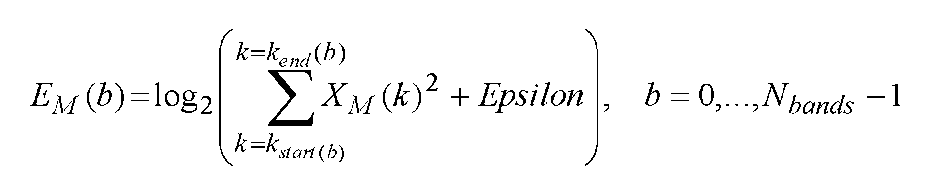
- the energy calculation unit 206 calculates the energy for each subband of the input signal S2. For example, when the input signal S2 is divided into subbands, the calculation can be performed using the sum of squares of the spectra in the subbands. For example, it can be defined by the following formula.
- X is an MDCT coefficient
- b is a subband number
- Epsilon is a constant for scalar quantization.
- the energy calculation unit 206 outputs an index indicating the obtained magnitude of the quantized band energy to the multiplexing unit 207 as the quantized band energy.
- the multiplexing unit 207 encodes the lag information, the scale factor, and the quantization band energy and multiplexes them. Then, the signal obtained by multiplexing is output as a high frequency encoded signal. Note that the multiplexing unit 207 and the multiplexing unit 103 may be provided separately or as a single unit.
- the gain calculation unit 205 (second calculation unit) generates the energy of the high frequency non-tonal (noise) component of the high frequency signal of the input signal and the low frequency decoded signal. Since the ratio of the high frequency non-tonal (noise) signal energy in the high frequency decoded signal is obtained, the energy of the non-tonal (noise) component in the decoded signal can be reproduced more accurately.
- the energy of the non-tonal component which is smaller than the tonal component and easily causes an error, can be more accurately reproduced, and the energy of the non-tonal component in the decoded signal is stabilized.
- the energy of the tonal component calculated using the band energy and the energy of the non-tonal component can be reproduced more accurately.
- the high frequency encoded signal can be encoded with a small number of bits.
- FIG. 3 is a block diagram showing a configuration of the second layer encoding unit 106 in the present embodiment.
- the difference from the second layer encoding unit 106 of Embodiment 1 is that the positional relationship between the noise addition unit and the separation unit is reversed, and the separation unit 302 and the noise addition unit 301 are provided.
- the separation unit 302 separates the low frequency decoded signal into a low frequency non-tonal signal that is a non-tonal component and a low frequency tonal signal that is a tonal component. As in the separation method described in the first embodiment, the separation is performed based on the magnitude of the amplitude based on a predetermined threshold.
- the threshold may be set to zero.
- the noise adding unit 301 adds a noise signal to the low frequency non-tonal signal output from the separating unit 302.
- the low-frequency decoded signal S1 may be referred to.
- Embodiment 1 is applicable also to what used except hierarchical encoding.
- 4 and 9 are examples of other encoding devices 110 and 610. FIG. First, the encoding device 110 in FIG. 4 will be described.
- a time-frequency conversion unit 111 includes a time-frequency conversion unit 111, a first encoding unit 112, a multiplexing unit 113, a band energy normalization unit 114, and a second encoding unit 115.
- the time-frequency conversion unit 111 performs frequency conversion on the input signal using MDCT or the like.
- the band energy normalization unit 114 calculates, quantizes, and encodes band energy for each predetermined band with respect to an input spectrum that is an input signal subjected to frequency conversion, and multiplexes the band energy encoded signal. It outputs to 113. Also, the band energy normalization unit 114 uses the quantized band energy to calculate bit allocation information B1 and B2 to be allocated to the first encoding unit and the second encoding unit, and the first encoding unit 112 and Each is output to second encoding section 115. Further, the band energy normalization unit 114 normalizes the input spectrum of each band with the quantized band energy, and the normalized input spectrum S2 is sent to the first encoding unit 112 and the second encoding unit 115. Output.
- the first encoding unit 112 performs first encoding on the normalized input spectrum S2 including a low frequency signal having a frequency equal to or lower than a predetermined frequency based on the input bit distribution information B1. Then, the first encoding unit 112 outputs the first encoded signal generated as a result of encoding to the multiplexing unit 113. Also, the first encoding unit 112 outputs the low frequency decoded signal S1 obtained in the encoding process to the second encoding unit 115.
- the second encoding unit 115 performs the second encoding for the portion of the normalized input spectrum S2 that has not been encoded by the first encoding unit 112.
- the second encoding unit 115 can use the configuration of the second layer encoding unit 106 described with reference to FIGS.
- the coding apparatus 610 shown in FIG. 9 includes a time-frequency conversion unit 611, a first coding unit 612, a multiplexing unit 613, and a second coding unit 614.
- the time-frequency conversion unit 611 performs frequency conversion on the input signal using MDCT or the like.
- the first encoding unit 612 performs band energy calculation, quantization, and encoding for each predetermined band on an input spectrum that is an input signal subjected to frequency change, and multiplexes the band energy encoded signal. To 613. In addition, the first encoding unit 612 calculates bit allocation information to be allocated to the first encoded signal and the second encoded signal using the quantized band energy, and based on the bit allocation information, the first encoding unit 612 has a predetermined frequency or less. The first encoding is performed on the normalized input spectrum S2 including the low-frequency signal.
- the first encoding unit 612 outputs the first encoded signal to the multiplexing unit 613 and secondly encodes a low-frequency decoded signal that is a low-frequency component in the decoded signal of the first encoded signal.
- the first encoding may be performed on the input signal normalized with the quantization band energy.
- the decoded signal of the first encoded signal is denormalized with the quantization band energy.
- the first encoding unit 612 outputs bit allocation information to be allocated to the second encoded signal and high-frequency quantization band energy information to the second encoding unit 614.
- the second encoding unit 614 performs second encoding for a portion of the input spectrum S2 that has not been encoded by the first encoding unit 612.
- the second encoding unit 614 can use the configuration of the second layer encoding unit 106 described with reference to FIGS.
- the bit allocation information is input to a band extension unit 208 that encodes lag information and a gain calculation unit that encodes a scale factor.
- 2 and 3 show an energy calculation unit 206 that calculates and quantizes band energy using an input signal.
- the first encoding unit 612 performs this processing. So it is not necessary.
- FIG. 5 is a block diagram of the configuration of the audio signal decoding apparatus according to the third embodiment.
- the encoded signal is a signal transmitted from an encoding apparatus having a hierarchical structure including a plurality of layers, and a decoding apparatus that decodes the encoded signal will be described as an example. An example having no hierarchical structure will be described with reference to FIG.
- 5 includes a separation unit 401, a first layer decoding unit 402, and a second layer decoding unit 403.
- an antenna (not shown) is connected to the separation unit 401.
- the separation unit 401 separates an encoded signal input via an antenna (not shown) into a low-frequency encoded signal and a high-frequency encoded signal that are first encoded signals. Separating section 401 outputs the low band encoded signal to first layer decoding section 402 and the high band encoded signal to second layer decoding section 403.
- 1st layer decoding part 402 is one form of a 1st decoding part, decodes a low frequency coding signal, and produces
- An example of decoding by the first layer decoding unit 402 is CELP decoding.
- First layer decoding section 402 outputs the low frequency decoded signal to second layer decoding section 403.
- the second layer decoding unit 403 is a form of the second decoding unit, decodes the high frequency encoded signal, generates and outputs a wideband decoded signal using the low frequency decoded signal. Details of second layer decoding section 403 will be described later.
- the low-band decoded signal and / or the wide-band decoded signal is reproduced through an amplifier or a speaker (not shown).
- FIG. 6 is a block diagram showing a configuration of the second layer decoding unit 403 in the present embodiment.
- Second layer decoding section 403 includes decoding / separating section 501, noise adding section 502, separating section 503, band expanding section 504, scaling section 505, combining section 506, adding section 507, band expanding section 508, combining section 509, tonal A signal energy estimation unit 510 and a scaling unit 511 are included.
- the decoding / separating unit 501 decodes the high-frequency encoded signal and separates it into quantization band energy A, scale factor B, and lag information C. Note that the separation unit 401 and the decoding / separation unit 501 may be provided separately or as a single unit.
- the noise adding unit 502 adds a noise signal to the low frequency decoded signal S1 input from the first layer decoding unit 402. As the noise signal, the same noise signal added by the noise adding unit 201 of the encoding apparatus 100 is used. Then, the noise adding unit 502 outputs the low frequency decoded signal added with the noise signal to the separating unit 503.
- the separation unit 503 separates the non-tonal component and the tonal component from the low frequency decoded signal to which the noise signal is added, and outputs the non-tonal component and the low frequency tonal signal, respectively.
- the method for separating the low-frequency non-tonal signal and the low-frequency tonal signal is the same as that described in the separation unit 202 of the encoding device 100.
- the band extension unit 504 uses the lag information C to copy the low frequency non-tonal signal of a specific band to the high frequency and generate a high frequency non-tonal signal.
- the scaling unit 505 adjusts the amplitude of the high frequency non-tonal signal by multiplying the high frequency non-tonal signal generated by the band expansion unit 504 by the scale factor B.
- the combining unit 506 combines the low frequency non-tonal signal and the high frequency non-tonal signal whose amplitude is adjusted by the scaling unit 505 to generate a wideband non-tonal signal.
- the low frequency tonal signal separated by the separation unit 503 is input to the band extension unit 508. Then, similarly to the band expanding unit 504, the band extending unit 508 uses the lag information C to copy the low band tonal signal of a specific band to the high band and generate a high band tonal signal.
- the tonal signal energy estimation unit 510 calculates the energy of the high frequency non-tonal signal with the amplitude adjusted from the scaling unit 505 and subtracts the energy of the high frequency non-tonal signal from the value of the quantization band energy A. Obtain the energy of the high frequency tonal signal. Then, the ratio of the energy of the high frequency non-tonal signal and the energy of the high frequency tonal signal is output to the scaling unit 511.
- the scaling unit 511 adjusts the amplitude of the high frequency tonal signal by multiplying the high frequency tonal signal by the ratio of the energy of the high frequency non-tonal signal and the energy of the high frequency tonal signal.
- the combining unit 509 combines the low frequency tonal signal and the high frequency tonal signal whose amplitude is adjusted to generate a wide band tonal signal.
- the adder 507 adds the wideband non-tonal signal and the wideband tonal signal to generate and output a wideband decoded signal.
- the low-frequency quantized spectrum is used to generate the non-tonal component with a small number of bits, and the scale factor is adjusted so as to have appropriate energy, and the adjusted non-tonal component energy is used. Since it has a configuration for adjusting the energy of the high frequency tonal signal, it can encode, transmit, and decode a music signal or the like with a small amount of information, and appropriately reproduce the energy of the high frequency non-tonal component. In addition, by determining the energy of the tonal component using the quantized band energy information and the energy information of the non-tonal component, the energy of the appropriate tonal component can also be reproduced.
- Embodiment 4 Next, the configuration of the decoding device according to Embodiment 4 of the present disclosure will be described with reference to FIG. Note that the overall configuration of the decoding apparatus 400 in this embodiment has the configuration shown in FIG. 4 as in the first embodiment.
- FIG. 7 is a block diagram showing a configuration of the second layer decoding unit 403 in the present embodiment.
- the difference from the second layer decoding unit 403 of the third embodiment is that, similarly to the relationship between the first and second embodiments, the positional relationship between the noise addition unit and the separation unit is reversed, and the separation unit 603 and the noise addition unit 602 are reversed. It is to have.
- the description of the decoding / separating unit 501 is omitted.
- the separation unit 603 separates the low frequency decoded signal into a low frequency non-tonal signal that is a non-tonal component and a low frequency tonal signal that is a tonal component.
- the noise adding unit 602 adds a noise signal to the low frequency non-tonal signal output from the separating unit 603.
- FIG. 8 and FIG. 10 are examples of other decoding apparatuses 410 and 620. First, the decoding device 410 shown in FIG. 8 will be described.
- a separation unit 411 includes a separation unit 411, a first decoding unit 412, a second decoding unit 413, a frequency-time conversion unit 414, a band energy inverse normalization unit 415, and a synthesis unit 116.
- the separating unit 411 separates an encoded signal input via an antenna (not shown) into a first encoded signal, a high frequency encoded signal, and a band energy encoded signal. Separating section 411 outputs the first encoded signal to first decoding section 412, the high frequency encoded signal to second decoding section 413, and the band energy encoded signal to band energy inverse normalization section 415.
- the band energy inverse quantization unit 415 decodes the band energy encoded signal to generate quantized band energy.
- the band energy inverse quantization unit 415 calculates the bit allocation information B1 and B2 to the first decoding unit and the second decoding unit based on the quantized band energy and outputs them. Further, the band energy inverse quantization unit 415 multiplies the generated quantized band energy by the normalized wideband decoded signal input from the synthesis unit 416 to perform denormalization to generate a final wideband decoded signal, Output to the frequency-time conversion unit 414.
- the first decoding unit 412 decodes the first encoded signal according to the bit allocation information B1, and generates a low-frequency decoded signal S1 and a high-frequency decoded signal.
- the first decoding unit 412 outputs the low frequency decoded signal to the second decoding unit 413 and the high frequency decoded signal to the synthesis unit 416, respectively.
- the second decoding unit 413 decodes the high frequency encoded signal according to the bit allocation information B2, and generates and outputs a wideband decoded signal using the low frequency decoded signal.
- the second decoding unit 413 can use the same configuration as the second layer decoding unit 403 described with reference to FIGS.
- the synthesizing unit 416 generates a normalized wideband decoded signal by adding the highband decoded signal decoded by the first decoding unit to the wideband decoded signal input from the second decoding unit, and outputs the normalized wideband decoded signal to the band energy inverse normalization unit 415 To do.
- the wideband decoded signal output from the band energy inverse normalization unit 415 is converted into a time domain signal by the frequency-time conversion unit 414 and reproduced through an amplifier or a speaker (not shown).
- FIG. 10 is an example of another decoding device 620.
- the decoding device 620 shown in FIG. 10 includes a first decoding unit 621, a second decoding unit 622, a combining unit 623, and a frequency-time conversion unit 624.
- the first decoding unit 621 receives an encoded signal (including a first encoded signal, a high frequency encoded signal, and a band energy encoded signal) input via an antenna (not shown), and first separates the band energy. Decrypt. The high band part of the decoded band energy is output to the second decoding part 622 as the high band energy (A). Next, the first decoding unit 621 calculates bit allocation information based on the decoded band energy, and separates and decodes the first encoded signal. This decoding process may include a denormalization process using the decoded band energy. The low frequency portion of the decoded first decoded signal is output to the second decoding portion 621 as a low frequency decoded signal.
- the first decoding unit 621 separates and decodes the high frequency encoded signal based on the bit allocation information.
- the decoded high frequency decoded signal includes a scale factor (B) and lag information (C), and outputs them to the second decoding unit 622. Further, the first decoding unit 621 outputs the high frequency part of the first decoded signal to the synthesizing part 623 as a high frequency decoded signal.
- the high frequency decoded signal may be zero.
- the second decoding unit 622 generates and outputs a wideband decoded signal using the low frequency decoded signal, the decoded quantized band energy, the scale factor, and the lag information input from the first decoding unit 621.
- the second decoding unit 622 may use the same configuration as the second layer decoding unit 403 described with reference to FIGS.
- the synthesis unit 623 generates a wideband decoded signal by adding the highband decoded signal decoded by the first decoding unit 621 to the wideband decoded signal input from the second decoding unit 622, and the frequency-time conversion unit 624 generates a time domain And reproduced through an amplifier or a speaker (not shown).
- the encoding device and the decoding device of the present disclosure have been described in the first to fourth embodiments.
- the encoding device and the decoding device of the present disclosure may be in a semi-finished product or component level form as represented by a system board or a semiconductor element, and also include a finished product level form such as a terminal device or a base station device. It is a concept.
- the decoding device and the coding device of the present disclosure are in a semi-finished product or a component level form, they are combined with an antenna, a DA / AD converter, an amplifier, a speaker, a microphone, and the like to obtain a finished product level form.
- FIGS. 1 to 10 represent the configuration and operation (method) of hardware designed exclusively, and a program that executes the operation (method) of the present disclosure is installed in general-purpose hardware. It also includes the case where it is realized by executing with a processor.
- general-purpose hardware electronic computers include personal computers, various portable information terminals such as smartphones, and mobile phones.
- the hardware designed for exclusive use is not limited to the finished product level (consumer electronics) such as a mobile phone and a fixed phone, but includes a semi-finished product and a component level such as a system board and a semiconductor element.
- the base station performs transcoding to change the voice encoding scheme.
- the base station is a concept including various nodes existing in the middle of the communication line.
- the encoding device and the decoding device according to the present disclosure can be applied to devices related to recording, transmission, and reproduction of audio signals and audio signals.
Abstract
Description
図1は、実施形態1にかかる音声信号等の符号化装置の構成を示すブロック図である。ここでは、符号化信号が複数のレイヤからなる階層構造を有する場合、すなわち階層符号化(スケーラブル符号化)を行う場合を例として説明する。階層符号化以外を含む例としては、後述の図4で説明する。図1に示す符号化装置100は、ダウンサンプリング部101、第1レイヤ符号化部102、多重化部103、第1レイヤ復号部104、遅延部105、第2レイヤ符号化部106より構成される。また、多重化部103には図示しないアンテナが接続されている。
次に、本開示の実施形態2における符号化装置の構成について、図3を用いて説明する。なお、本実施形態における符号化装置100全体の構成は、実施形態1と同様、図1の構成を有している。
図5は、実施形態3にかかる音声信号復号装置の構成を示すブロック図である。ここでは、符号化信号が複数のレイヤからなる階層構造を有する符号化装置から送信された信号であり、この符号化信号を復号する復号装置を例として説明する。なお、階層構造を有さない例については、図8で説明する。
次に、本開示の実施形態4における復号装置の構成を図7を用いて説明する。なお、本実施形態における復号装置400全体の構成は、実施形態1と同様、図4の構成を有している。
以上、実施形態1から4で本開示の符号化装置および復号装置を説明した。本開示の符号化装置および復号装置は、システムボードや半導体素子に代表されるような半完成品や部品レベルの形態でもよいし、端末装置や基地局装置のような完成品レベルの形態も含む概念である。本開示の復号装置および符号化装置が半完成品や部品レベルの形態の場合は、アンテナ、DA/ADコンバータ、増幅器、スピーカ、およびマイク等と組み合わせることにより完成品レベルの形態となる。
101 ダウンサンプリング部
102 第1レイヤ符号化部
103,113,613 多重化部
104 第1レイヤ復号部
105 遅延部
106 第2レイヤ符号化部
201,301 雑音加算部
202,302 分離部
203 帯域拡張部
204 雑音成分エネルギー算出部(第1計算部)
205 ゲイン算出部(第2計算部)
206 エネルギー計算部
207 多重化部
208 帯域拡張部
400,410,620 復号装置
401,411 分離部
402 第1レイヤ復号部
403 第2レイヤ復号部
501 復号・分離部
502,602 雑音加算部
503,603 分離部
504 帯域拡張部
505 スケーリング部
506 結合部
507 加算部
508 帯域拡張部
509 結合部
510 トーナル信号エネルギー推定部
511 スケーリング部
112,612 第1符号化部
115,614 第2符号化部
412,621 第1復号部
413,622 第2復号部
Claims (17)
- 音声またはオーディオ入力信号の所定周波数以下の低域信号を符号化して第1符号化信号を生成し、前記第1符号化信号を復号して低域復号信号を生成する第1符号化部と、
前記低域復号信号に基づいて、前記低域信号より高域の信号を符号化して高域符号化信号を生成する第2符号化部と、
前記第1符号化信号と前記高域符号化信号とを多重化して符号化信号を出力する第1の多重化部、とを有し、
前記第2符号化部は、
前記高域信号の雑音成分である高域雑音成分と、前記低域復号信号から生成された高域復号信号の高域非トーナル成分とのエネルギー比率を算出して、高域符号化信号として出力する、
符号化装置。 - 前記音声またはオーディオ入力信号のエネルギーを計算して量子化バンドエネルギーとして出力するエネルギー計算部と、を更に備え、
前記第1の多重化部は、前記量子化バンドエネルギーと前記第1符号化信号と前記高域符号化信号とを多重化して出力する、
請求項1に記載の符号化装置。 - 前記第2符号化部は、
前記低域復号信号を、前記低域復号信号の非トーナル成分である低域非トーナル信号と、前記低域復号信号のトーナル成分である低域トーナル信号と、に分離する分離部と、
前記高域信号と前記低域トーナル信号との間の相関を最大とする特定の帯域の位置情報をラグ情報として出力する第1の帯域拡張部と、
前記ラグ情報に対応する前記低域非トーナル信号を高域非トーナル信号として出力する第2の帯域拡張部と、
前記ラグ情報に対応する前記高域信号から、雑音成分である高域雑音成分のエネルギーを計算する第1計算部と、
前記比率を前記高域雑音成分と前記高域非トーナル信号とのエネルギー比率から算出し、スケールファクタとして出力する第2計算部と、
前記ラグ情報および前記スケールファクタを多重化して高域符号化信号として出力する第2の多重化部と、を有する、
請求項2記載の符号化装置。 - 前記第2符号化部は、
前記低域復号信号に雑音信号を加算する雑音加算部をさらに有する、
請求項3記載の符号化装置。 - 前記第2符号化部は、
前記分離部から出力された前記低域非トーナル信号に雑音信号を加算する雑音加算部をさらに有する、
請求項3記載の符号化装置。 - 符号化装置において、音声またはオーディオ入力信号の所定周波数以下の低域信号を符号化した第1符号化信号、および前記低域信号より高域の信号を符号化した高域符号化信号が入力される復号装置であって、
前記第1符号化信号および前記高域符号化信号に分離する分離部と、
前記第1符号化信号を復号して低域復号信号を生成する第1復号部と、
前記高域符号化信号を復号し、前記低域復号信号を用いて広帯域復号信号を生成する第2復号部と、を有し、
前記高域符号化信号は、雑音成分である高域雑音成分と、前記低域復号信号から生成された高域復号信号の高域非トーナル成分とのエネルギー比率を含み、
前記第2復号部は、
復号された前記比率を参照して前記低域復号信号の非トーナル成分である低域非トーナル信号の振幅を調整する、
復号装置。 - 符号化装置において、音声またはオーディオ入力信号の所定周波数以下の低域信号を符号化した第1符号化信号、前記低域信号よりも高域の信号を符号化した高域符号化信号、およびバンドエネルギー符号化信号が入力される復号装置であって、
前記第1符号化信号を復号して低域復号信号を生成する第1復号部と、
前記高域符号化信号を復号し、前記低域復号信号を用いて広帯域復号信号を生成する第2復号部と、
前記バンドエネルギー符号化信号を復号して量子化バンドエネルギーを生成する第3復号部と、を有し、
前記第2復号部は、
前記低域復号信号を、前記低域復号信号の非トーナル成分である低域非トーナル信号と、前記低域復号信号のトーナル成分である低域トーナル信号とに分離する分離部と、
前記高域符号化信号を復号して得られるラグ情報を用いて前記低域非トーナル信号を高域にコピーして高域非トーナル信号を生成する第1の帯域拡張部と、
前記高域符号化信号を復号して得られるスケールファクタを用いて前記高域非トーナル信号の振幅を調整する第1のスケーリング部と、
前記高域非トーナル信号のエネルギーと前記量子化バンドエネルギーとから、高域トーナル信号のエネルギーを推定するトーナル信号エネルギー推定部と、
前記低域非トーナル信号と前記高域非トーナル信号を結合して広帯域非トーナル信号を生成する第1の結合部と、
前記ラグ情報を用いて前記低域トーナル信号を高域にコピーして高域トーナル信号を生成する第2の帯域拡張部と、
前記高域トーナル信号のエネルギーに基づき、前記高域トーナル信号の振幅を調整する第2のスケーリング部と、
前記低域トーナル信号と振幅を調整された前記高域トーナル信号を結合して広帯域トーナル信号を生成する第2の結合部と、
前記広帯域非トーナル信号と前記広帯域トーナル信号とを加算して広帯域復号信号を生成する加算部と、を有し、
前記ラグ情報は、高域信号と低域トーナル信号との間の相関を最大とする特定の帯域の位置情報であり、
前記スケールファクタは、前記ラグ情報に対応する高域信号の雑音成分である高域雑音成分と高域非トーナル信号とのエネルギー比率である、
復号装置。 - 前記第2復号部は、
前記低域復号信号に雑音信号を加算する雑音加算部をさらに有する、
請求項6記載の復号装置。 - 前記第2復号部は、
前記分離部から出力された前記低域非トーナル信号に雑音信号を加算する雑音加算部をさらに有する、
請求項6記載の復号装置。 - 請求項1に記載の符号化装置を有する端末装置。
- 請求項6に記載の復号装置を有する端末装置。
- 音声またはオーディオ入力信号の所定周波数以下の低域信号を符号化して第1符号化信号を生成し、
前記第1符号化信号を復号して低域復号信号を生成し、
前記低域復号信号に基づいて、前記低域信号より高域の信号を符号化して高域符号化信号を生成し、
前記高域信号の雑音成分である高域雑音成分と、前記低域復号信号から生成された高域復号信号の高域非トーナル成分とのエネルギー比率を算出し、
前記第1符号化信号と、前記比率を含む高域符号化信号とを多重化して符号化信号を出力する、
符号化方法。 - 請求項12に記載の符号化方法は、
前記音声またはオーディオ入力信号のエネルギーを計算して量子化バンドエネルギーとして出力し、
前記低域復号信号を、前記低域復号信号の非トーナル成分である低域非トーナル信号と、前記低域復号信号のトーナル成分である低域トーナル信号と、に分離し、
前記高域信号と前記低域トーナル信号との間の相関を最大とする特定の帯域の位置情報をラグ情報として出力し、
前記ラグ情報に対応する前記低域非トーナル信号を高域非トーナル信号として出力し、
前記ラグ情報に対応する前記高域信号から、雑音成分である高域雑音成分のエネルギーを計算し、
前記高域雑音成分と前記高域非トーナル信号とのエネルギー比率を算出してスケールファクタとして出力する、
符号化方法。 - 符号化装置において音声またはオーディオ入力信号の所定周波数以下の低域信号を符号化した第1符号化信号、および前記低域信号より高域の信号を符号化した高域符号化信号について、
前記第1符号化信号および前記高域符号化信号に分離し、
前記第1符号化信号を復号して低域復号信号を生成し、
前記高域符号化信号を復号し、前記低域復号信号を用いて広帯域復号信号を生成し、
前記高域符号化信号は、雑音成分である高域雑音成分と、前記低域復号信号から生成された高域復号信号の高域非トーナル成分とのエネルギー比率を含み、
復号された前記比率を生成し、前記比率を参照して前記低域復号信号の非トーナル成分である低域非トーナル信号の振幅を調整する、
復号方法。 - 符号化装置において音声またはオーディオ入力信号の所定周波数以下の低域信号を符号化した第1符号化信号、前記低域信号より高域の信号を符号化した高域符号化信号、およびバンドエネルギー符号化信号について、
前記第1符号化信号を復号して低域復号信号を生成し、
前記高域符号化信号を復号し、前記低域復号信号を用いて広帯域復号信号を生成し、
前記バンドエネルギー符号化信号を復号して量子化バンドエネルギーを生成し、
前記低域復号信号を、前記低域復号信号の非トーナル成分である低域非トーナル信号と、前記低域復号信号のトーナル成分である低域トーナル信号と、に分離し、
前記高域符号化信号を復号して得られるラグ情報を用いて前記低域非トーナル信号を高域にコピーして高域非トーナル信号を生成し、
前記高域符号化信号を復号して得られるスケールファクタを用いて前記高域非トーナル信号の振幅を調整し、
前記高域非トーナル信号のエネルギーと前記量子化バンドエネルギーとから、高域トーナル信号のエネルギーを推定し、
前記低域非トーナル信号と前記高域非トーナル信号を結合して広帯域非トーナル信号を生成し、
前記ラグ情報を用いて前記低域トーナル信号を高域にコピーして高域トーナル信号を生成し、
前記高域トーナル信号のエネルギーに基づき、前記高域トーナル信号の振幅を調整し、
前記低域トーナル信号と振幅を調整された前記高域トーナル信号を結合して広帯域トーナル信号を生成し、
前記広帯域非トーナル信号と前記広帯域トーナル信号とを加算して広帯域復号信号を生成し、
前記ラグ情報は、高域信号と低域トーナル信号との間の相関を最大とする特定の帯域の位置情報であり、
前記スケールファクタは、前記ラグ情報に対応する高域信号の雑音成分である高域雑音成分と高域非トーナル信号とのエネルギー比率である、
復号方法。 - 音声またはオーディオの入力信号の所定周波数以下の低域信号を符号化して第1符号化信号を生成する処理と、
前記第1符号化信号を復号して低域復号信号を生成する処理と、
前記低域復号信号に基づいて、前記低域信号より高域の信号を符号化して高域符号化信号を生成する処理と、
前記高域信号の雑音成分である高域雑音成分と、前記低域復号信号から生成された高域復号信号の高域非トーナル成分とのエネルギー比率を算出する処理と、
前記第1符号化信号と、前記比率を含む高域符号化信号とを多重化して符号化信号を出力する処理と、をプロセッサに実行させるプログラム。 - 符号化装置において音声またはオーディオの入力信号の所定周波数以下の低域信号を符号化した第1符号化信号、および前記低域信号より高域の信号を符号化した高域符号化信号について、
前記第1符号化信号および前記高域符号化信号に分離する処理と、
前記第1符号化信号を復号して低域復号信号を生成する処理と、
前記高域符号化信号を復号し、前記低域復号信号を用いて広帯域復号信号を生成する処理と、
前記高域符号化信号は、雑音成分である高域雑音成分と、前記低域復号信号から生成された高域復号信号の高域非トーナル成分とのエネルギー比率を含み、
復号された前記比率を生成し、前記比率を参照して前記低域復号信号の非トーナル成分である低域非トーナル信号の振幅を調整する処理と、をプロセッサに実行させるプログラム。
Priority Applications (14)
| Application Number | Priority Date | Filing Date | Title |
|---|---|---|---|
| PL15774034T PL3128513T3 (pl) | 2014-03-31 | 2015-03-23 | Koder, dekoder, sposób kodowania, sposób dekodowania i program |
| BR112016019838-7A BR112016019838B1 (pt) | 2014-03-31 | 2015-03-23 | Codificador de áudio, decodificador de áudio, método de codificação, método de decodificação e mídia de registro legível por computador não transitória |
| ES15774034T ES2737889T3 (es) | 2014-03-31 | 2015-03-23 | Codificador, decodificador, procedimiento de codificación, procedimiento de decodificación y programa |
| JP2016511368A JPWO2015151451A1 (ja) | 2014-03-31 | 2015-03-23 | 符号化装置、復号装置、符号化方法、復号方法、およびプログラム |
| RU2016138694A RU2689181C2 (ru) | 2014-03-31 | 2015-03-23 | Кодер, декодер, способ кодирования, способ декодирования и программа |
| CN202010460132.8A CN111710342B (zh) | 2014-03-31 | 2015-03-23 | 编码装置、解码装置、编码方法、解码方法及程序 |
| KR1020167012900A KR102121642B1 (ko) | 2014-03-31 | 2015-03-23 | 부호화 장치, 복호 장치, 부호화 방법, 복호 방법, 및 프로그램 |
| EP15774034.1A EP3128513B1 (en) | 2014-03-31 | 2015-03-23 | Encoder, decoder, encoding method, decoding method, and program |
| EP19174461.4A EP3550563B1 (en) | 2014-03-31 | 2015-03-23 | Encoder, decoder, encoding method, decoding method, and associated programs |
| MX2016010595A MX367639B (es) | 2014-03-31 | 2015-03-23 | Codificador, decodificador, método de codificación, método de decodificación y programa. |
| CN201580003573.2A CN105874534B (zh) | 2014-03-31 | 2015-03-23 | 编码装置、解码装置、编码方法、解码方法及程序 |
| US15/221,425 US10269361B2 (en) | 2014-03-31 | 2016-07-27 | Encoding device, decoding device, encoding method, decoding method, and non-transitory computer-readable recording medium |
| US16/295,387 US11232803B2 (en) | 2014-03-31 | 2019-03-07 | Encoding device, decoding device, encoding method, decoding method, and non-transitory computer-readable recording medium |
| US17/573,360 US20220130402A1 (en) | 2014-03-31 | 2022-01-11 | Encoding device, decoding device, encoding method, decoding method, and non-transitory computer-readable recording medium |
Applications Claiming Priority (4)
| Application Number | Priority Date | Filing Date | Title |
|---|---|---|---|
| US201461972722P | 2014-03-31 | 2014-03-31 | |
| US61/972,722 | 2014-03-31 | ||
| JP2014-153832 | 2014-07-29 | ||
| JP2014153832 | 2014-07-29 |
Related Child Applications (1)
| Application Number | Title | Priority Date | Filing Date |
|---|---|---|---|
| US15/221,425 Continuation US10269361B2 (en) | 2014-03-31 | 2016-07-27 | Encoding device, decoding device, encoding method, decoding method, and non-transitory computer-readable recording medium |
Publications (1)
| Publication Number | Publication Date |
|---|---|
| WO2015151451A1 true WO2015151451A1 (ja) | 2015-10-08 |
Family
ID=54239798
Family Applications (1)
| Application Number | Title | Priority Date | Filing Date |
|---|---|---|---|
| PCT/JP2015/001601 WO2015151451A1 (ja) | 2014-03-31 | 2015-03-23 | 符号化装置、復号装置、符号化方法、復号方法、およびプログラム |
Country Status (10)
| Country | Link |
|---|---|
| US (3) | US10269361B2 (ja) |
| EP (2) | EP3550563B1 (ja) |
| JP (1) | JPWO2015151451A1 (ja) |
| KR (1) | KR102121642B1 (ja) |
| CN (2) | CN105874534B (ja) |
| BR (1) | BR112016019838B1 (ja) |
| MX (1) | MX367639B (ja) |
| PL (1) | PL3128513T3 (ja) |
| RU (1) | RU2689181C2 (ja) |
| WO (1) | WO2015151451A1 (ja) |
Cited By (3)
| Publication number | Priority date | Publication date | Assignee | Title |
|---|---|---|---|---|
| JP2017227701A (ja) * | 2016-06-21 | 2017-12-28 | 日本電信電話株式会社 | 音声符号化装置、音声復号装置、音声符号化方法、音声復号方法、プログラム、および記録媒体 |
| JP2019070823A (ja) * | 2014-07-25 | 2019-05-09 | フラウンホッファー−ゲゼルシャフト ツァ フェルダールング デァ アンゲヴァンテン フォアシュンク エー.ファオ | 音響信号符号化装置、音響信号復号装置、音響信号符号化方法および音響信号復号方法 |
| US10643623B2 (en) | 2014-07-25 | 2020-05-05 | Fraunhofer-Gesellschaft Zur Foerderung Der Angewandten Forschung E.V. | Audio signal coding apparatus, audio signal decoding apparatus, audio signal coding method, and audio signal decoding method |
Families Citing this family (2)
| Publication number | Priority date | Publication date | Assignee | Title |
|---|---|---|---|---|
| PL3128513T3 (pl) * | 2014-03-31 | 2019-11-29 | Fraunhofer Ges Forschung | Koder, dekoder, sposób kodowania, sposób dekodowania i program |
| CN113192523A (zh) * | 2020-01-13 | 2021-07-30 | 华为技术有限公司 | 一种音频编解码方法和音频编解码设备 |
Citations (2)
| Publication number | Priority date | Publication date | Assignee | Title |
|---|---|---|---|---|
| JP2010020251A (ja) * | 2008-07-14 | 2010-01-28 | Ntt Docomo Inc | 音声符号化装置及び方法、音声復号化装置及び方法、並びに、音声帯域拡張装置及び方法 |
| JP2011075728A (ja) * | 2009-09-29 | 2011-04-14 | Oki Electric Industry Co Ltd | 音声帯域拡張装置および音声帯域拡張プログラム |
Family Cites Families (48)
| Publication number | Priority date | Publication date | Assignee | Title |
|---|---|---|---|---|
| JP3277699B2 (ja) * | 1994-06-13 | 2002-04-22 | ソニー株式会社 | 信号符号化方法及び装置並びに信号復号化方法及び装置 |
| JP3557674B2 (ja) * | 1994-12-15 | 2004-08-25 | ソニー株式会社 | 高能率符号化方法及び装置 |
| SE512719C2 (sv) | 1997-06-10 | 2000-05-02 | Lars Gustaf Liljeryd | En metod och anordning för reduktion av dataflöde baserad på harmonisk bandbreddsexpansion |
| SE9903553D0 (sv) * | 1999-01-27 | 1999-10-01 | Lars Liljeryd | Enhancing percepptual performance of SBR and related coding methods by adaptive noise addition (ANA) and noise substitution limiting (NSL) |
| JP4173940B2 (ja) | 1999-03-05 | 2008-10-29 | 松下電器産業株式会社 | 音声符号化装置及び音声符号化方法 |
| EP1423847B1 (en) * | 2001-11-29 | 2005-02-02 | Coding Technologies AB | Reconstruction of high frequency components |
| US7333930B2 (en) * | 2003-03-14 | 2008-02-19 | Agere Systems Inc. | Tonal analysis for perceptual audio coding using a compressed spectral representation |
| CN1677492A (zh) * | 2004-04-01 | 2005-10-05 | 北京宫羽数字技术有限责任公司 | 一种增强音频编解码装置及方法 |
| CN101656077B (zh) * | 2004-05-14 | 2012-08-29 | 松下电器产业株式会社 | 音频编码装置、音频编码方法以及通信终端和基站装置 |
| EP3336843B1 (en) | 2004-05-14 | 2021-06-23 | Panasonic Intellectual Property Corporation of America | Speech coding method and speech coding apparatus |
| WO2006107837A1 (en) * | 2005-04-01 | 2006-10-12 | Qualcomm Incorporated | Methods and apparatus for encoding and decoding an highband portion of a speech signal |
| FR2888699A1 (fr) * | 2005-07-13 | 2007-01-19 | France Telecom | Dispositif de codage/decodage hierachique |
| CN101371296B (zh) * | 2006-01-18 | 2012-08-29 | Lg电子株式会社 | 用于编码和解码信号的设备和方法 |
| CN101336451B (zh) * | 2006-01-31 | 2012-09-05 | 西门子企业通讯有限责任两合公司 | 音频信号编码的方法和装置 |
| JP2008058727A (ja) * | 2006-08-31 | 2008-03-13 | Toshiba Corp | 音声符号化装置 |
| EP2063418A4 (en) * | 2006-09-15 | 2010-12-15 | Panasonic Corp | AUDIO CODING DEVICE AND AUDIO CODING METHOD |
| US8015368B2 (en) * | 2007-04-20 | 2011-09-06 | Siport, Inc. | Processor extensions for accelerating spectral band replication |
| US8990073B2 (en) | 2007-06-22 | 2015-03-24 | Voiceage Corporation | Method and device for sound activity detection and sound signal classification |
| US9177569B2 (en) * | 2007-10-30 | 2015-11-03 | Samsung Electronics Co., Ltd. | Apparatus, medium and method to encode and decode high frequency signal |
| WO2009084221A1 (ja) * | 2007-12-27 | 2009-07-09 | Panasonic Corporation | 符号化装置、復号装置およびこれらの方法 |
| DE102008015702B4 (de) * | 2008-01-31 | 2010-03-11 | Fraunhofer-Gesellschaft zur Förderung der angewandten Forschung e.V. | Vorrichtung und Verfahren zur Bandbreitenerweiterung eines Audiosignals |
| JP5247826B2 (ja) * | 2008-03-05 | 2013-07-24 | ヴォイスエイジ・コーポレーション | 復号化音調音響信号を増強するためのシステムおよび方法 |
| MX2011000382A (es) * | 2008-07-11 | 2011-02-25 | Fraunhofer Ges Forschung | Codificador de audio, decodificador de audio, metodos para la codificacion y decodificacion de audio; transmision de audio y programa de computacion. |
| US8352279B2 (en) * | 2008-09-06 | 2013-01-08 | Huawei Technologies Co., Ltd. | Efficient temporal envelope coding approach by prediction between low band signal and high band signal |
| EP2945159B1 (en) * | 2008-12-15 | 2018-03-21 | Fraunhofer-Gesellschaft zur Förderung der angewandten Forschung e.V. | Audio encoder and bandwidth extension decoder |
| JP5511785B2 (ja) * | 2009-02-26 | 2014-06-04 | パナソニック株式会社 | 符号化装置、復号装置およびこれらの方法 |
| AU2014201331B2 (en) * | 2009-06-29 | 2015-10-01 | Fraunhofer-Gesellschaft Zur Foerderung Der Angewandten Forschung E.V. | Bandwidth extension encoder, bandwidth extension decoder and phase vocoder |
| PL2273493T3 (pl) * | 2009-06-29 | 2013-07-31 | Fraunhofer Ges Forschung | Kodowanie i dekodowanie z rozszerzaniem szerokości pasma |
| FR2947945A1 (fr) * | 2009-07-07 | 2011-01-14 | France Telecom | Allocation de bits dans un codage/decodage d'amelioration d'un codage/decodage hierarchique de signaux audionumeriques |
| JP5652658B2 (ja) * | 2010-04-13 | 2015-01-14 | ソニー株式会社 | 信号処理装置および方法、符号化装置および方法、復号装置および方法、並びにプログラム |
| US8306493B2 (en) | 2010-04-13 | 2012-11-06 | Newport Media, Inc. | Pilot based adaptation for FM radio receiver |
| ES2719102T3 (es) * | 2010-04-16 | 2019-07-08 | Fraunhofer Ges Forschung | Aparato, procedimiento y programa informático para generar una señal de banda ancha que utiliza extensión de ancho de banda guiada y extensión de ancho de banda ciega |
| WO2012005209A1 (ja) | 2010-07-05 | 2012-01-12 | 日本電信電話株式会社 | 符号化方法、復号方法、装置、プログラム及び記録媒体 |
| US9047875B2 (en) * | 2010-07-19 | 2015-06-02 | Futurewei Technologies, Inc. | Spectrum flatness control for bandwidth extension |
| KR101826331B1 (ko) * | 2010-09-15 | 2018-03-22 | 삼성전자주식회사 | 고주파수 대역폭 확장을 위한 부호화/복호화 장치 및 방법 |
| CN102436820B (zh) * | 2010-09-29 | 2013-08-28 | 华为技术有限公司 | 高频带信号编码方法及装置、高频带信号解码方法及装置 |
| CA2836122C (en) | 2011-05-13 | 2020-06-23 | Samsung Electronics Co., Ltd. | Bit allocating, audio encoding and decoding |
| CN102800317B (zh) * | 2011-05-25 | 2014-09-17 | 华为技术有限公司 | 信号分类方法及设备、编解码方法及设备 |
| KR102078865B1 (ko) * | 2011-06-30 | 2020-02-19 | 삼성전자주식회사 | 대역폭 확장신호 생성장치 및 방법 |
| CN102208188B (zh) * | 2011-07-13 | 2013-04-17 | 华为技术有限公司 | 音频信号编解码方法和设备 |
| CN106847295B (zh) * | 2011-09-09 | 2021-03-23 | 松下电器(美国)知识产权公司 | 编码装置和编码方法 |
| EP2791937B1 (en) * | 2011-11-02 | 2016-06-08 | Telefonaktiebolaget LM Ericsson (publ) | Generation of a high band extension of a bandwidth extended audio signal |
| CN103187065B (zh) * | 2011-12-30 | 2015-12-16 | 华为技术有限公司 | 音频数据的处理方法、装置和系统 |
| US9478221B2 (en) * | 2013-02-05 | 2016-10-25 | Telefonaktiebolaget Lm Ericsson (Publ) | Enhanced audio frame loss concealment |
| JP2014153832A (ja) | 2013-02-06 | 2014-08-25 | Seiko Instruments Inc | 携帯型電子機器用のカバー |
| US9489959B2 (en) * | 2013-06-11 | 2016-11-08 | Panasonic Intellectual Property Corporation Of America | Device and method for bandwidth extension for audio signals |
| US9615185B2 (en) * | 2014-03-25 | 2017-04-04 | Bose Corporation | Dynamic sound adjustment |
| PL3128513T3 (pl) * | 2014-03-31 | 2019-11-29 | Fraunhofer Ges Forschung | Koder, dekoder, sposób kodowania, sposób dekodowania i program |
-
2015
- 2015-03-23 PL PL15774034T patent/PL3128513T3/pl unknown
- 2015-03-23 RU RU2016138694A patent/RU2689181C2/ru active
- 2015-03-23 WO PCT/JP2015/001601 patent/WO2015151451A1/ja active Application Filing
- 2015-03-23 EP EP19174461.4A patent/EP3550563B1/en active Active
- 2015-03-23 BR BR112016019838-7A patent/BR112016019838B1/pt active IP Right Grant
- 2015-03-23 MX MX2016010595A patent/MX367639B/es active IP Right Grant
- 2015-03-23 CN CN201580003573.2A patent/CN105874534B/zh active Active
- 2015-03-23 KR KR1020167012900A patent/KR102121642B1/ko active IP Right Grant
- 2015-03-23 EP EP15774034.1A patent/EP3128513B1/en active Active
- 2015-03-23 CN CN202010460132.8A patent/CN111710342B/zh active Active
- 2015-03-23 JP JP2016511368A patent/JPWO2015151451A1/ja active Pending
-
2016
- 2016-07-27 US US15/221,425 patent/US10269361B2/en active Active
-
2019
- 2019-03-07 US US16/295,387 patent/US11232803B2/en active Active
-
2022
- 2022-01-11 US US17/573,360 patent/US20220130402A1/en active Pending
Patent Citations (2)
| Publication number | Priority date | Publication date | Assignee | Title |
|---|---|---|---|---|
| JP2010020251A (ja) * | 2008-07-14 | 2010-01-28 | Ntt Docomo Inc | 音声符号化装置及び方法、音声復号化装置及び方法、並びに、音声帯域拡張装置及び方法 |
| JP2011075728A (ja) * | 2009-09-29 | 2011-04-14 | Oki Electric Industry Co Ltd | 音声帯域拡張装置および音声帯域拡張プログラム |
Non-Patent Citations (1)
| Title |
|---|
| See also references of EP3128513A4 * |
Cited By (4)
| Publication number | Priority date | Publication date | Assignee | Title |
|---|---|---|---|---|
| JP2019070823A (ja) * | 2014-07-25 | 2019-05-09 | フラウンホッファー−ゲゼルシャフト ツァ フェルダールング デァ アンゲヴァンテン フォアシュンク エー.ファオ | 音響信号符号化装置、音響信号復号装置、音響信号符号化方法および音響信号復号方法 |
| US10643623B2 (en) | 2014-07-25 | 2020-05-05 | Fraunhofer-Gesellschaft Zur Foerderung Der Angewandten Forschung E.V. | Audio signal coding apparatus, audio signal decoding apparatus, audio signal coding method, and audio signal decoding method |
| US11521625B2 (en) | 2014-07-25 | 2022-12-06 | Fraunhofer-Gesellschaft Zur Foerderung Der Angewandten Forschung E.V. | Audio signal coding apparatus, audio signal decoding apparatus, audio signal coding method, and audio signal decoding method |
| JP2017227701A (ja) * | 2016-06-21 | 2017-12-28 | 日本電信電話株式会社 | 音声符号化装置、音声復号装置、音声符号化方法、音声復号方法、プログラム、および記録媒体 |
Also Published As
| Publication number | Publication date |
|---|---|
| CN111710342A (zh) | 2020-09-25 |
| US20160336017A1 (en) | 2016-11-17 |
| EP3128513A4 (en) | 2017-03-29 |
| EP3128513A1 (en) | 2017-02-08 |
| US10269361B2 (en) | 2019-04-23 |
| US20220130402A1 (en) | 2022-04-28 |
| JPWO2015151451A1 (ja) | 2017-04-13 |
| US20190251979A1 (en) | 2019-08-15 |
| EP3550563A1 (en) | 2019-10-09 |
| EP3550563C0 (en) | 2024-03-06 |
| PL3128513T3 (pl) | 2019-11-29 |
| CN111710342B (zh) | 2024-04-16 |
| CN105874534A (zh) | 2016-08-17 |
| MX2016010595A (es) | 2016-11-29 |
| RU2016138694A (ru) | 2018-05-07 |
| BR112016019838A2 (ja) | 2017-08-15 |
| US11232803B2 (en) | 2022-01-25 |
| KR102121642B1 (ko) | 2020-06-10 |
| EP3128513B1 (en) | 2019-05-15 |
| KR20160138373A (ko) | 2016-12-05 |
| MX367639B (es) | 2019-08-29 |
| EP3550563B1 (en) | 2024-03-06 |
| CN105874534B (zh) | 2020-06-19 |
| RU2689181C2 (ru) | 2019-05-24 |
| RU2016138694A3 (ja) | 2018-08-27 |
| BR112016019838B1 (pt) | 2023-02-23 |
Similar Documents
| Publication | Publication Date | Title |
|---|---|---|
| US10685660B2 (en) | Voice audio encoding device, voice audio decoding device, voice audio encoding method, and voice audio decoding method | |
| US7983904B2 (en) | Scalable decoding apparatus and scalable encoding apparatus | |
| US11232803B2 (en) | Encoding device, decoding device, encoding method, decoding method, and non-transitory computer-readable recording medium | |
| US10643623B2 (en) | Audio signal coding apparatus, audio signal decoding apparatus, audio signal coding method, and audio signal decoding method | |
| WO2009093466A1 (ja) | 符号化装置、復号装置およびこれらの方法 | |
| JP2015512528A (ja) | 帯域幅拡張のための高周波数符号化/復号化方法及びその装置 | |
| US9230551B2 (en) | Audio encoder or decoder apparatus | |
| JPWO2008132850A1 (ja) | ステレオ音声符号化装置、ステレオ音声復号装置、およびこれらの方法 | |
| KR102185478B1 (ko) | 복호 장치, 부호화 장치, 복호 방법, 및 부호화 방법 | |
| JP6957444B2 (ja) | 音響信号符号化装置、音響信号復号装置、音響信号符号化方法および音響信号復号方法 | |
| WO2011058752A1 (ja) | 符号化装置、復号装置およびこれらの方法 |
Legal Events
| Date | Code | Title | Description |
|---|---|---|---|
| 121 | Ep: the epo has been informed by wipo that ep was designated in this application |
Ref document number: 15774034 Country of ref document: EP Kind code of ref document: A1 |
|
| ENP | Entry into the national phase |
Ref document number: 20167012900 Country of ref document: KR Kind code of ref document: A |
|
| REEP | Request for entry into the european phase |
Ref document number: 2015774034 Country of ref document: EP |
|
| ENP | Entry into the national phase |
Ref document number: 2016511368 Country of ref document: JP Kind code of ref document: A |
|
| WWE | Wipo information: entry into national phase |
Ref document number: MX/A/2016/010595 Country of ref document: MX |
|
| NENP | Non-entry into the national phase |
Ref country code: DE |
|
| ENP | Entry into the national phase |
Ref document number: 2016138694 Country of ref document: RU Kind code of ref document: A |
|
| REG | Reference to national code |
Ref country code: BR Ref legal event code: B01A Ref document number: 112016019838 Country of ref document: BR |
|
| ENP | Entry into the national phase |
Ref document number: 112016019838 Country of ref document: BR Kind code of ref document: A2 Effective date: 20160826 |