WO2015146474A1 - 浴室ユニット及びその施工方法 - Google Patents
浴室ユニット及びその施工方法 Download PDFInfo
- Publication number
- WO2015146474A1 WO2015146474A1 PCT/JP2015/055783 JP2015055783W WO2015146474A1 WO 2015146474 A1 WO2015146474 A1 WO 2015146474A1 JP 2015055783 W JP2015055783 W JP 2015055783W WO 2015146474 A1 WO2015146474 A1 WO 2015146474A1
- Authority
- WO
- WIPO (PCT)
- Prior art keywords
- ceiling
- supply pipe
- panel
- water supply
- water
- Prior art date
- Legal status (The legal status is an assumption and is not a legal conclusion. Google has not performed a legal analysis and makes no representation as to the accuracy of the status listed.)
- Ceased
Links
Images


Classifications
-
- A—HUMAN NECESSITIES
- A47—FURNITURE; DOMESTIC ARTICLES OR APPLIANCES; COFFEE MILLS; SPICE MILLS; SUCTION CLEANERS IN GENERAL
- A47K—SANITARY EQUIPMENT; ACCESSORIES THEREFOR, e.g. TOILET ACCESSORIES
- A47K3/00—Baths; Showers; Appurtenances therefor
- A47K3/28—Showers or bathing douches
Definitions
- the present invention relates to a bathroom unit that includes a bathroom partitioned by a wall panel and a ceiling panel, and has a ceiling water discharger that discharges hot water from the ceiling into the bathroom.
- a bathroom unit such as a unit bath has been proposed that has a hot water function for discharging hot water from the ceiling (for example, see Patent Document 1).
- the bathroom unit described in Patent Document 1 is connected to a switching unit (mixed faucet) provided on the side wall and a switching unit and a switching unit in the bathroom partitioned by the side wall and the upper wall.
- a pipe for hot water is supported along the inner surface of the side wall. This pipe for tapping hot water extends upward along the inner surface of the side wall, penetrates the hole in the upper wall to reach the ceiling back space, and is connected to the spout provided on the other upper wall via this ceiling back space.
- Patent Document 2 A cover structure that conceals such piping has been proposed (see, for example, Patent Document 2).
- the cover structure described in Patent Document 2 is for concealing a pipe extending up and down along the inner wall surface of the bathroom and extending through the ceiling, and a pipe cover unit having a U-shaped cross section is formed on the inner wall surface. The pipe is fixed and accommodated in the pipe cover unit.
- An object of the present invention is to provide a bathroom unit and its construction method capable of improving construction efficiency by reducing labor and time of connection and installation work of piping and equipment, even for a bathroom unit having a ceiling water discharging part. It is to provide.
- the bathroom unit of the present invention is a bathroom unit including a bathroom partitioned by a wall panel and a ceiling panel, and having a ceiling water discharger that discharges hot water from the ceiling into the bathroom.
- a water discharging member provided on the ceiling panel and having a water outlet opening into the bathroom, a ceiling water supply pipe extending along the back surface of the ceiling panel and having one end connected to the water discharging member, and penetrating the ceiling panel
- a water supply pipe connecting portion connected to the other end of the ceiling back water supply pipe, and including the ceiling panel and a continuous specific ceiling panel that can be handled as a single panel, the water discharge member and the ceiling back
- a water supply pipe and the water supply pipe connecting portion are provided.
- the water discharge member, the ceiling back water supply pipe, and the water supply pipe connecting portion are provided on the continuous specific ceiling panel that can be handled as a single panel.
- the ceiling water supply pipe connected to one end of the ceiling is disposed on the back side of the ceiling, and the specific ceiling panel in which the water discharging member and the ceiling water supply pipe are assembled in advance in the predetermined position of the bathroom unit. By attaching, the installation work and connection work in the ceiling space can be omitted.
- the water supply pipe connection part may be connected to the other end of the ceiling back water supply pipe in advance and attached to the specific ceiling panel, or when using a water supply pipe connection part that can be connected from the bathroom side, You may connect from the bathroom side to the other end of a ceiling water supply pipe after installation of a specific ceiling panel.
- the continuous specific ceiling panel that can be handled as a single panel may be a single ceiling panel, or a plurality of ceilings that are connected to each other and can be handled integrally. It may be composed of panels.
- a water discharge member is provided on one of the plurality of ceiling panels, and a ceiling back water pipe is provided across the other ceiling panels.
- a water supply pipe connection portion may be provided on the ceiling panel where the end is located, or a water discharge member or a water supply pipe connection portion is provided at a boundary portion of the plurality of ceiling panels, and they are connected by an arbitrary route to the ceiling.
- a back water supply pipe may be provided.
- the specific ceiling panel in the present invention is formed continuously from one or a plurality of ceiling panels in which a water discharge member is provided at a predetermined location and a ceiling back water supply pipe is disposed on the ceiling back surface side.
- the water supply pipe connection portion may be attached in advance, or the water supply pipe connection portion may be attached later. .
- the wall panel water pipe extending vertically along the bathroom inner wall surface of the wall panel and connected to the water pipe connecting portion, and the wall panel bathroom covering the wall water pipe
- a wall surface case attached to the inner wall surface, and the wall surface housing is preferably provided with an operation unit for discharging the ceiling water discharge unit.
- the wall surface case is attached to the wall surface of the bathroom of the wall panel, the operation unit is provided on the wall surface case, and the wall surface water supply pipe is covered by the wall surface case.
- the tube is not exposed inside the bathroom, and the design of the inner wall surface can be improved.
- the pipe cover unit described in Patent Document 2 when a member for simply concealing the piping is provided, the piping can be concealed, but the pipe cover unit itself has an unnatural impression. Is unavoidable to deteriorate design.
- the wall surface water supply pipe is covered with the wall surface housing having the operation part as in the present invention, the wall surface water supply pipe can be concealed without feeling unnatural.
- a second water discharge member provided on the ceiling surface side of the specific ceiling panel, and a ceiling housing attached to the ceiling surface side of the specific ceiling panel together with the second water discharge member
- the wall surface housing is provided with a second operation portion for performing water discharge operation on the second water discharge member, and the wall surface housing and the ceiling housing are connected to form a continuous cover body, It is preferable that the water supply pipe connection portion is covered with the cover body.
- the ceiling housing is attached together with the second water discharge member on the ceiling surface side of the specific ceiling panel, the second water discharge member is not exposed inside the bathroom, and the design of the ceiling surface Can be improved. Furthermore, since the water supply pipe connection part is covered by the cover body connecting the wall surface case and the ceiling case, only the inverted L-shaped cover body is visible from the inside of the bathroom, and the wall surface water supply pipe and the water supply pipe connection part The second water discharge member and the like are not visually recognized, and the beauty inside the bathroom can be further improved.
- the other end of the ceiling back water pipe is provided facing a through hole provided in the ceiling panel, and the water pipe connecting part penetrates the through hole from the ceiling surface side. And it is preferable that it is connected to the other end part of the said ceiling back water supply pipe.
- the specific ceiling panel is connected to the predetermined part of the bathroom unit by connecting the water supply pipe connection portion from the ceiling surface side to the other end portion of the ceiling back water supply pipe provided facing the through hole of the ceiling panel.
- the connection work of a water supply pipe connection part can be implemented from the inside of a bathroom, and workability can be further improved.
- the specific ceiling panel assembled with the water discharging member and the ceiling back water supply pipe in advance can be transported or the bathroom unit.
- the water supply pipe connection portion can be prevented from projecting to the surface side of the specific ceiling panel, and the transportability and installation workability of the specific ceiling panel can be improved.
- the bathroom unit construction method of the present invention is any one of the bathroom unit construction methods described above, wherein the water discharge member and the ceiling water supply pipe are connected and can be handled as a single panel.
- the specific ceiling panel is attached to a predetermined position of the bathroom unit after being attached to the ceiling panel.
- the water discharge member and the ceiling back water supply pipe are assembled in advance to the continuous specific ceiling panel that can be handled as a single panel.
- installation work and connection work in the ceiling space can be omitted.
- the work of attaching or connecting the water discharge member or the ceiling back water supply pipe in the ceiling space can be omitted. It is possible to reduce construction time and improve construction efficiency.
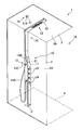
- the bathroom unit 1 of the present embodiment includes a plurality of wall panels 2 and a ceiling panel 3, a wash floor (waterproof pan) 4, a bathtub waterproof pan and a bathtub (not shown), A bathroom 1A that is supported by a waterproof pan for a bathtub (not shown), a bathroom doorway, a window, and the like and is partitioned by these is configured.
- the wall panel 2 and the ceiling panel 3 are each composed of a steel plate panel having an appropriate decorative surface on the inside of the bathroom 1A and a gypsum board affixed to the back surface of the steel plate, and a base material (not shown) It is fixed to the skeleton).
- the bathroom unit 1 is provided with a shower device 10.
- the shower device 10 includes a device main body 11 provided on a bathroom inner wall surface 2A constituting one side of a washing place, a currant portion 12 provided at a lower end portion of the device main body 11, and a hand connected to a side surface of the device main body 11.
- a ceiling shower (overhead shower) unit 15 a ceiling shower (overhead shower) unit 15.
- the apparatus main body 11 includes a wall surface casing 21 attached to the bathroom inner wall surface 2 ⁇ / b> A of the wall panel 2, and hot water supply pipes and valves (not shown) provided in the wall surface casing 21. .
- the hot water supply pipe is connected to a water heater provided outside (outdoor) of the bathroom 1A, and connected to an appropriate mixing valve, and then branched by a branch pipe. 13, connected to the hot water hot water 14 and the ceiling shower 15.
- Two pipes connected to the tapping hot water section 14 and the ceiling shower section 15 among the hot water supply pipes extend upward from the switching valve and are provided along the bathroom inner wall surface 2A of the wall panel 2. 23 (see FIGS. 3 and 4).
- the wall surface casing 21 is formed in a hollow box shape elongated in the vertical direction, and is fixed to a plurality of brackets (not shown) provided on the wall surface 2A in the bathroom.
- the lower side of the wall surface casing 21 is formed with a large protruding dimension from the bathroom inner wall surface 2A, and a plurality of (four in this embodiment) operation sections 24 are provided on the front surface thereof.
- the upper side of the wall surface casing 21 is formed with a small projecting dimension from the bathroom inner wall surface 2A, and wall surface water supply pipes 22 and 23 are passed through the inside.
- the lowermost operation unit 24 is an operation unit for adjusting hot water temperature connected to the mixing valve
- the second operation unit 24 from the bottom is a switching valve for the currant unit 12 and the hand shower unit 13. It is connected.
- the second operation unit 24 from the top is connected to the switching valve of the ceiling shower unit 15, and the uppermost operation unit 24 is connected to the switching valve of the hot water bath unit 14.
- the currant 12 is provided on the bottom surface of the wall surface casing 21 so as to be able to discharge water downward, and is discharged by the second operation unit 24 from the bottom.
- the hand shower unit 13 is provided at a shower hose 13 ⁇ / b> A connected to a joint projecting from the side surface of the wall surface housing 21, a shower head 13 ⁇ / b> B provided at the tip of the shower hose 13 ⁇ / b> A, and an upper side surface of the wall surface housing 21.
- the shower hook 13 ⁇ / b> C is configured so that the water discharge operation can be performed by the second operation unit 24 from the bottom.
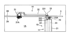
- the hot water hot water portion 14 is provided along the water discharge member 31 having the water discharge port 31 ⁇ / b> A provided in the ceiling panel 3 and opening in the bathroom 1 ⁇ / b> A, and the ceiling back surface 3 ⁇ / b> B of the ceiling panel 3.
- the ceiling water supply pipe 32 having one end connected to the extended water discharge member 31 and the water supply pipe connecting part 33 penetrating the ceiling panel 3 and connected to the other end of the ceiling water supply pipe 32 are configured. Yes.
- the water supply pipe connecting portion 33 is connected to the wall surface water supply pipe 22 via an L-shaped joint 22A.
- the hammered hot water section 14 is configured to discharge water by the uppermost operation section 24 and to intermittently drop the hot water from the water outlet 31A.
- the wash floor 4 is provided with a seat for a bather to sit below the hot water bath 14 so that the dropped hot water can be applied to the shoulder or the like.
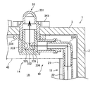
- the water supply pipe connecting portion 33 is provided on the ceiling back surface 3B side of the ceiling panel 3 and connected to the ceiling back water supply pipe 32, and is provided on the ceiling surface 3A side and screwed into the first joint 331.
- the second joint 332, the third joint 333 that is inserted through the second joint 332 and connected to the joint 22A of the wall surface water supply pipe 22, and the first joint 331 are screwed into the ceiling panel 3 from the ceiling surface 3A side.
- a holding member 334 for holding for holding.
- the second joint 332 has a plurality of through holes 335 that penetrate the pipe peripheral surface, and the third joint 333 has an insertion hole 336 through which the second joint 332 is inserted.
- the second joint 332 and the third joint 333 are configured by so-called banjo joints in which the internal joints are communicated with each other through the through-hole 335 by inserting the second joint 332 through the insertion hole 336. ing.
- a support member 34 for supporting the hot water bath 14 on the ceiling panel 3 is provided.
- the support member 34 includes a beam portion 341 linearly extending from the water discharge member 31 to the water supply pipe connection portion 33, a first support plate portion 342 coupled to one end portion of the beam portion 341, and the other end portion of the beam portion 341. And a second support plate portion 343 to be connected.
- the first support plate portion 342 is sandwiched between the water discharge member 31 and the ceiling back surface 3B, thereby supporting the water discharge member 31 while reinforcing the ceiling panel 3, and the second support plate portion 343 is a water supply pipe connection portion.
- the ceiling shower unit 15 includes a second water discharge member 41 connected to the wall surface water supply pipe 23 and having a plurality of water discharge ports, and a slide bracket fixed to the ceiling surface 3 ⁇ / b> A of the ceiling panel 3. 42 and a ceiling housing 43 that covers the second water discharge member 41 and is attached to the ceiling surface 3 ⁇ / b> A side of the ceiling panel 3 via the slide bracket 42.
- the second water discharge member 41 is connected to the wall surface water supply pipe 23 via a one-touch joint 44 and an L-shaped joint 23A.
- the ceiling shower unit 15 is configured to discharge water by a second operation unit 24 from the top, and to discharge hot water from a plurality of water outlets. That is, the second operation unit is configured by the second operation unit 24 from the top in the wall surface casing 21.
- the second water discharge member 41 is built in the ceiling housing 43 and is integrally handled.
- the ceiling housing 43 is formed in an overall box shape in which two surfaces of one side surface on the wall panel 2 side and the upper surface on the ceiling panel 3 side are opened, and a plurality of discharges of the second water discharge member 41 are formed on the lower surface. A plurality of holes corresponding to the water ports are formed.
- the ceiling housing 43 is attached to the ceiling panel 3 by being slid toward the wall panel 2 along the slide bracket 42, and is connected to the upper end portion of the wall surface housing 21 in this attached state.
- the wall case 21 and the ceiling case 43 connected in this way constitute the L-shaped continuous cover body 16, and the water supply pipe connection portion 33 is covered by the cover body 16.
- the ceiling panel 3 provided with the tapping hot water section 14 and the ceiling shower section 15 as described above is a continuous specific ceiling panel that can be handled as a single panel.
- the specific ceiling panel of the present embodiment is composed of a single ceiling panel 3, and the ceiling panel 3 is located above the washing area in the ceiling portion of the bathroom unit 1. It constitutes the ceiling part.
- the bathroom unit 1 is also provided with another ceiling panel (not shown) that constitutes a ceiling part located above the bathtub.
- a specific ceiling panel it is not restricted to what is comprised by the ceiling panel 3 of 1 sheet, You may be comprised by the ceiling panel 3 of several sheets which can be mutually connected and can be handled integrally. .
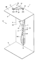
- One ceiling panel 3 as such a specific ceiling panel is in a state before being attached to the bathroom unit 1 (pre-attachment state), as shown in FIG. A semi-assembled state in which some members are assembled.
- the ceiling panel 3 includes a water discharge member 31, a ceiling back water supply pipe 32, a first joint 331 and a holding member 334 of the water supply pipe connection portion 33, and a support member 34.
- the slide bracket 42 of the ceiling shower portion 15 is attached in advance.
- the water discharge member 31 and one end of the ceiling back water supply pipe 32 are connected, the other end of the ceiling back water supply pipe 32 and the first joint 331 of the water supply pipe connecting part 33 are connected, and the first joint 331
- the holding member 334 is screwed together. That is, the first joint 331 constituting the other end portion of the ceiling back water supply pipe 32 is provided facing the through hole of the ceiling panel 3 and is opened to the ceiling surface 3A side of the ceiling panel 3. Further, the first support plate portion 342 is sandwiched between the water discharge member 31 and the ceiling back surface 3B, and the second support plate portion 343 is sandwiched between the first joint 331 and the ceiling back surface 3B. Is attached to the ceiling panel 3.
- a waterproof pan (washing floor 4 and a waterproof pan for a bathtub) of the bathroom unit 1 and a bathtub are installed, and a plurality of wall panels 2 are attached to the frame.
- the hot water supply pipe (including the wall surface water supply pipes 22 and 23) of the apparatus main body 11 is disposed on the wall panel 2 of the washing place, and the wall surface casing 21 is attached to the wall panel 2 so as to cover the hot water supply pipe.
- the upper end of the wall surface casing 21 is provided at a position lower than the upper edge of the wall panel 2 (the ceiling surface 3 ⁇ / b> A of the ceiling panel 3).
- a gap substantially the same as the height of the ceiling casing 43 is formed between the upper end of the casing 21 and the ceiling surface 3A.
- the ceiling panel 3 in the semi-assembled state as described above is transported, and as shown in FIG. 6A, it is connected to the upper end edge of the wall panel 2 so as to be in a predetermined position (above the washing area). ).
- the bathroom 1A divided by these is comprised.
- the second joint 332 and the third joint 333 of the water supply pipe connecting portion 33 are attached to the wall panel 2 and the ceiling panel 3 from the inside of the bathroom 1A.
- the second joint 332 is inserted into the insertion hole 336 of the third joint 333, and the second joint 332 is The water supply pipe connecting portion 33 is assembled by screwing into the first joint 331.
- work of the tapping hot water part 14 is completed.
- the ceiling housing 43 incorporating the second water discharge member 41 of the ceiling shower unit 15 is placed along the slide bracket 42 of the ceiling panel 3, and as shown in FIGS.
- the body 43 is attached by sliding toward the wall panel 2. Accordingly, the one-touch joint 44 of the second water discharge member 41 is fitted into the joint 23A of the wall surface water supply pipe 23, and the second water discharge member 41 and the wall surface water supply pipe 23 are connected. Furthermore, by sliding the ceiling housing 43 until it abuts against the wall panel 2, the upper end of the wall surface housing 21 and the ceiling housing 43 are connected as shown in FIG.
- the water pipe connecting portion 33 is covered by the cover body 16. Thereafter, the ceiling housing 43 is fixed to the wall surface housing 21 by an appropriate fixing means, and the installation work and piping connection work of the hot water hot water 14 and the ceiling shower 15 are completed.
- the water discharging member 31, the water supply pipe 32, the first back joint pipe 331, the holding member 334 and the support member 34 of the hot water portion 14 struck on the ceiling panel 3 and the slide bracket 42 of the ceiling shower unit 15 are attached in advance.
- the ceiling panel 3 By attaching the ceiling panel 3 to a predetermined position of the bathroom unit 1 in a semi-assembled state, installation work and connection work in the ceiling space can be omitted. Accordingly, it is possible to improve the construction efficiency of the bathroom unit 1 by reducing the labor and time of the installation work and connection work of the shower device 10.
- the second joint 332 and the third joint 333 of the water supply pipe connection portion 33 in the hot water portion 14 struck from the inside of the bathroom 1A are attached, and then the ceiling shower portion 15
- the ceiling housing 43 is slid along the slide bracket 42 and attached to the ceiling panel 3, so that the installation work and the pipe connection work for the hot water bath 14 and the ceiling shower 15 are performed from the inside of the bathroom 1A. be able to. Therefore, the workability of the installation work of the shower apparatus 10 can be further improved.
- the ceiling panel 3 can be transported.
- the ceiling panel 3 in a semi-assembled state can be reduced in weight, and the second joint 332 and the third joint 333 can be prevented from projecting greatly on the surface side of the ceiling panel 3.
- the transportability and installation workability of the panel 3 can be improved.
- the support member 34 is provided on the ceiling back surface 3B side of the ceiling panel 3, the ceiling panel 3 can be reinforced by the support member 34, and deformation and breakage of the ceiling panel 3 can be prevented.
- the wall surface water supply pipes 22 and 23 are not exposed inside the bathroom 1A.
- the design of the inner wall surface of the bathroom 1A can be improved.
- the wall case 21 and the ceiling case 41 are connected to form a continuous cover body 16, and the wall surface water supply pipes 22 and 23 and the water supply pipe connection portion 33 are covered by the cover body 16, so that the shower The aesthetics inside the apparatus 10 and the bathroom 1A can be further improved.
- the shower device 10 is provided with the currant unit 12, the hand shower unit 13, the hot water bathing unit 14, and the ceiling shower unit 15.
- the bathroom unit of the present invention has a ceiling water discharge unit (soaked water). What is necessary is just to comprise the hot water part 14), and the currant part 12, the hand shower part 13, and the ceiling shower part 15 can be abbreviate
- the ceiling water discharger is not limited to one that intermittently discharges hot water such as the tapping hot water unit 14 of the above embodiment, but is a shower unit having a plurality of water discharge ports such as the ceiling shower unit 15. May be.
- the water discharge member 31 is provided on any one of the ceiling panels 3, the ceiling back water supply pipe 33 is provided across the other ceiling panels, and the other end of the ceiling back water supply pipe 33 is located.
- the water supply pipe connection part 33 may be provided in the ceiling panel, or the water discharge member 31 and the water supply pipe connection part 33 are provided in the boundary part of the plurality of ceiling panels, and they are connected by an arbitrary route to the ceiling.
- a water supply pipe 32 may be provided.
- the 2nd joint 332 and the 3rd joint 333 are not attached to the ceiling panel 3 of a semi-assembly
- the attachment procedure of attaching the second joint 332 and the third joint 333 and connecting to the wall surface water supply pipe 22 was adopted, but not limited to this, the second joint 332 and the third joint 333 are connected.
- the included water supply pipe connecting portion 33 may be attached to the ceiling panel 3 in advance.
- the water supply pipe connecting portion is not limited to the one having the first joint 331, the second joint 332, and the third joint 333 as in the above embodiment, but is a general L-shaped joint or a crank-shaped joint. There may be.
- the water supply pipe connection part is configured with a slide joint, or a slide joint is provided between the water supply pipe connection part and the wall surface water supply pipe. You may comprise so that a part and a wall surface water supply pipe can be connected.
- the slide bracket 42 of the ceiling shower part 15 shall be previously attached to the ceiling panel 3 made into the semi-attached state
- the slide bracket 42 makes the ceiling panel 3 the predetermined
- the slide bracket 42 can be fixed at an accurate position with respect to the apparatus main body 11 and the wall surface casing 21 of the wall panel 2, and the wall surface casing can be obtained by attaching the ceiling casing 43 along the slide bracket 42. 21 and the ceiling housing 43 are connected with high accuracy, and the appearance of the cover body 16 constituted by these can be improved.
- the wall panel 2 and the ceiling panel 3 shall be comprised with a steel plate panel
- what was comprised with arbitrary materials can be used for a wall panel and a ceiling panel, for example, a resin panel, A tile panel, a wood panel, a glass panel, a composite panel in which different materials are laminated, or the like may be employed.
- the structure in which the shower apparatus 10 was provided in a washing place was illustrated, it may be provided in the bathtub part not only in this, but also in the shower apparatus 10, the ceiling water discharging part (bath water) 14) may be provided above the bathtub, and the currant unit 12, the hand shower unit 13, and the ceiling shower unit 15 may be provided in the washing area.
- casing 41 was employ
- the ceiling casing 43 is slid toward the wall panel 2 and attached to the ceiling panel 3.
- the present invention is not limited to this, and the ceiling casing faces from the lower side to the upper ceiling panel. It may be attached using an engaging means that engages by pressing, or may be attached to the ceiling panel by a fixing means such as a screw.
Landscapes
- Health & Medical Sciences (AREA)
- Public Health (AREA)
- Epidemiology (AREA)
- General Health & Medical Sciences (AREA)
- Bathtubs, Showers, And Their Attachments (AREA)
Abstract
天井吐水部を備えた浴室ユニットであっても配管や機器の接続、設置作業の手間や時間を削減して施工効率の向上を図ることができる浴室ユニット及びその施工方法を提供する。 打たせ湯部(天井吐水部)(14)は、天井パネル(3)に設けられて浴室(1A)内に開口する吐水口を有する吐水部材(31)と、天井パネルの天井裏面(3B)に沿って延び吐水部材に一端部が接続される天井裏給水管(32)と、天井パネル3を貫通して天井裏給水管32の他端に接続される給水管接続部(33)と、を備え、吐水部材と天井裏給水管と給水管接続部とが1枚のパネルとして取扱い可能な連続した天井パネル3に設けられている。
Description
本発明は、壁パネル及び天井パネルによって区画された浴室を構成するとともに、天井から浴室内に湯水を吐水する天井吐水部を備えた浴室ユニット及びその施工方法に関する。
従来、ユニットバス等の浴室ユニットにおいて、天井から湯水を吐出する打たせ湯機能を備えたものが提案されている(例えば、特許文献1参照)。特許文献1に記載された浴室ユニットは、側壁及び上壁で区画した浴室内部において、側壁に設けられた切替ユニット(混合水栓)にカランとシャワーとが接続されるとともに、切替ユニットに接続された打たせ湯用配管が側壁内面に沿って支持されている。この打たせ湯用配管は、側壁内面に沿って上方に延び、上壁の孔を貫通して天井裏空間に至り、この天井裏空間を経由して他の上壁に設けた吐水口に接続されている。
ところで、特許文献1に記載された打たせ湯用配管のように、浴室内部の側壁に露出して設けられる配管では、利用者が触れてしまう可能性があるとともに意匠性が劣ることから、このような配管を隠蔽するようなカバー構造が提案されている(例えば、特許文献2参照)。特許文献2に記載されたカバー構造は、浴室の内壁面に沿って上下に延びるとともに天井を貫通して延びる配管を隠蔽するためのものであって、断面U字形のパイプカバーユニットを内壁面に固定し、このパイプカバーユニットの内部に配管を収容するように構成されている。
しかしながら、特許文献1に記載されたような従来の浴室ユニットでは、打たせ湯用配管を吐水口に接続する敷設作業を天井裏空間にて行う必要があり、狭い天井裏空間での敷設作業となることから施工性が悪化してしまう。また、特許文献2に記載されたような配管構造であっても、その上端部は天井を貫通して天井裏空間まで延びて設けられるのみであり、この配管と天井裏の機器(ミストサウナ装置等)を接続するためには天井裏空間における接続作業が必要になってしまう。以上のように、従来の浴室ユニットにおける配管構造では、いずれの場合でも、天井裏空間における作業が発生することから、配管や機器を設置するために多大な手間と時間を要し、施工効率が低下してしまうという問題があった。
本発明の目的は、天井吐水部を備えた浴室ユニットであっても配管や機器の接続、設置作業の手間や時間を削減して施工効率の向上を図ることができる浴室ユニット及びその施工方法を提供することにある。
本発明の浴室ユニットは、壁パネル及び天井パネルによって区画された浴室を構成するとともに、天井から浴室内に湯水を吐水する天井吐水部を備えた浴室ユニットであって、前記天井吐水部は、前記天井パネルに設けられて浴室内に開口する吐水口を有する吐水部材と、前記天井パネルの天井裏面に沿って延び前記吐水部材に一端部が接続される天井裏給水管と、前記天井パネルを貫通して前記天井裏給水管の他端に接続される給水管接続部と、を備え、前記天井パネルを含むとともに1枚のパネルとして取扱い可能な連続した特定天井パネルに前記吐水部材と前記天井裏給水管と前記給水管接続部とが設けられていることを特徴とする。
以上のような本発明によれば、1枚のパネルとして取扱い可能な連続した特定天井パネルに吐水部材と天井裏給水管と給水管接続部とが設けられるので、この特定天井パネルに吐水部材を取り付けておくとともに、その一端部に接続した天井裏給水管を天井裏面側に配設しておき、そのように予め吐水部材及び天井裏給水管を組み付けた特定天井パネルを浴室ユニットの所定位置に取り付けることで、天井裏空間での取付作業や接続作業を省略することができる。なお、給水管接続部は、予め天井裏給水管の他端に接続して特定天井パネルに取り付けておいてもよいし、浴室側から接続可能な構成の給水管接続部を用いる場合には、特定天井パネルの設置後に浴室側から天井裏給水管の他端に接続してもよい。
ここで、本発明において、1枚のパネルとして取扱い可能な連続した特定天井パネルとしては、1枚の天井パネルであってもよいし、互いに連結されて一体的に取り扱うことができる複数枚の天井パネルで構成されるものであってもよい。複数枚の天井パネルで構成される場合には、複数のうちいずれかの天井パネルに吐水部材が設けられ、他の天井パネルに亘って天井裏給水管が設けられ、その天井裏給水管の他端が位置する天井パネルに給水管接続部が設けられていてもよいし、複数枚の天井パネルの境界部分に吐水部材や給水管接続部が設けられ、それらを任意の経路で接続して天井裏給水管が設けられていてもよい。
以上のように、本発明における特定天井パネルとは、その所定箇所に吐水部材が設けられるとともに、天井裏面側に天井裏給水管が配設された単数又は複数の天井パネルから連続して形成されたものであって、1枚のパネルとして一体的に取扱うに際して、予め給水管接続部が取り付けられたものでもよいし、後から給水管接続部が取り付け可能に構成されたものであってもよい。
この際、本発明の浴室ユニットでは、前記壁パネルの浴室内壁面に沿って上下に延びて前記給水管接続部に接続される壁面給水管と、前記壁面給水管を覆って前記壁パネルの浴室内壁面に取り付けられる壁面筐体と、をさらに備え、前記壁面筐体には、前記天井吐水部を吐水操作するための操作部が設けられていることが好ましい。
このような構成によれば、壁パネルの浴室内壁面に壁面筐体が取り付けられ、この壁面筐体に操作部が設けられるとともに、壁面筐体によって壁面給水管が覆われているので、壁面給水管が浴室内部に露出することがなく、内壁面の意匠性を良好にすることができる。ここで、前記特許文献2に記載されたパイプカバーユニットのように、単に配管を隠蔽するための部材を設けた場合には、配管を隠すことはできるものの、パイプカバーユニット自体が不自然な印象を利用者に与えることから意匠性の低下を免れない。これに対して、本発明のように操作部を有する壁面筐体によって壁面給水管を覆うようにすれば、不自然さを感じさせることなく壁面給水管を隠蔽することができる。
さらに、本発明の浴室ユニットでは、前記特定天井パネルの天井表面側に設けられる第二吐水部材と、前記第二吐水部材とともに前記特定天井パネルの天井表面側に取り付けられる天井筐体と、をさらに備え、前記壁面筐体には、前記第二吐水部材を吐水操作するための第二操作部が設けられ、前記壁面筐体と前記天井筐体とが接続されて連続したカバー体が構成され、該カバー体に前記給水管接続部が覆われていることが好ましい。
このような構成によれば、特定天井パネルの天井表面側に第二吐水部材とともに天井筐体が取り付けられているので、第二吐水部材が浴室内部に露出することがなく、天井面の意匠性を良好にすることができる。さらに、壁面筐体と天井筐体とを接続したカバー体によって給水管接続部が覆われるので、浴室内部からは逆L字形のカバー体が視認されるのみとなり、壁面給水管や給水管接続部、第二吐水部材などが視認されることがなくなり、浴室内部の美観を一層向上させることができる。
また、本発明の浴室ユニットでは、前記天井裏給水管の他端部が前記天井パネルに設けられた貫通孔に臨んで設けられ、前記給水管接続部は、天井表面側から前記貫通孔を貫通して前記天井裏給水管の他端部に接続されていることが好ましい。
このような構成によれば、天井パネルの貫通孔に臨んで設けられた天井裏給水管の他端部に天井表面側から給水管接続部を接続することで、特定天井パネルを浴室ユニットの所定位置に取り付けた後に給水管接続部の接続作業を浴室内部側から実施することができ、施工性をさらに向上させることができる。また、特定天井パネルを浴室ユニットに設置する際には、まだ給水管接続部を接続しておく必要がないので、予め吐水部材及び天井裏給水管を組み付けた特定天井パネルを運搬したり浴室ユニットに設置したりする際に、特定天井パネルの表面側に給水管接続部が突出しないようにでき、特定天井パネルの運搬性や設置作業性を良好にすることができる。
一方、本発明の浴室ユニットの施工方法は、前記いずれかの浴室ユニットの施工方法であって、前記吐水部材と前記天井裏給水管とを接続するとともに1枚のパネルとして取扱い可能な連続した特定天井パネルに取り付けてから、該特定天井パネルを前記浴室ユニットの所定位置に取り付けることを特徴とする。
以上のような本発明によれば、前述した浴室ユニットの発明と同様に、1枚のパネルとして取扱い可能な連続した特定天井パネルに吐水部材と天井裏給水管とを予め組み付けておき、この特定天井パネルを浴室ユニットの所定位置に取り付けることで、天井裏空間での取付作業や接続作業を省略することができる。
以上のような本発明の浴室ユニット及びその施工方法によれば、吐水部材や天井裏給水管を天井裏空間において取り付けたり接続したりする作業を省略することができるので、そのような作業の手間や時間を削減して施工効率の向上を図ることができる。
以下、本発明の実施形態を図面に基づいて説明する。本実施形態の浴室ユニット1は、図1、2に示すように、それぞれ複数の壁パネル2及び天井パネル3と、洗い場床(防水パン)4及び浴槽用防水パン及び浴槽(不図示)と、浴槽用防水パンに支持される(不図示)と、浴室出入口や窓等と、を備え、これらによって区画された浴室1Aを構成するものである。壁パネル2及び天井パネル3は、それぞれ浴室1A内部側に適宜な化粧面を有する鋼板と、この鋼板の裏面に貼付される石膏ボードと、を有した鋼板パネルで構成され、図示しない下地材(骨組)に固定されている。
浴室ユニット1には、シャワー装置10が設けられている。このシャワー装置10は、洗い場の一側面を構成する浴室内壁面2Aに設けられる装置本体11と、この装置本体11の下端部に設けられるカラン部12と、装置本体11の側面に接続されるハンドシャワー部13と、装置本体11の上部に接続されて洗い場の天井パネル3に設けられる天井吐水部としての打たせ湯部14と、装置本体11の上部に接続されて洗い場の天井表面3Aに設けられる天井シャワー(オーバーヘッドシャワー)部15と、を備えて構成されている。
装置本体11は、壁パネル2の浴室内壁面2Aに取り付けられる壁面筐体21と、この壁面筐体21の内部に設けられる給湯配管やバルブ等(不図示)と、を備えて構成されている。給湯配管は、浴室1Aの外部(屋外)に設けられた給湯器などに接続されるとともに、適宜な混合バルブに接続されてから分岐管によって分岐され、切替バルブを介してカラン12、ハンドシャワー部13、打たせ湯部14及び天井シャワー部15にそれぞれ接続されている。給湯配管のうち打たせ湯部14及び天井シャワー部15に接続される2本の配管は、切替バルブから上方に延びて壁パネル2の浴室内壁面2Aに沿って設けられた壁面給水管22,23(図3、4参照)とされている。
壁面筐体21は、上下方向に細長い中空箱型に形成されるとともに、浴室内壁面2Aに設けられる図示しない複数のブラケットに固定されている。この壁面筐体21の下部側は、浴室内壁面2Aからの出寸法が大きく形成され、その前面に複数(本実施形態では、4つ)の操作部24が設けられている。壁面筐体21の上部側は、浴室内壁面2Aからの出寸法が小さく形成され、その内部に壁面給水管22,23が通されている。操作部24のうち、最下段の操作部24は混合バルブに接続された湯温調整用の操作部であり、下から二番目の操作部24はカラン部12及びハンドシャワー部13の切替バルブに接続されている。また、上から二番目の操作部24は天井シャワー部15の切替バルブに接続され、最上段の操作部24は打たせ湯部14の切替バルブに接続されている。
カラン部12は、壁面筐体21の底面部に設けられて下方に吐水可能に設けられ、下から二番目の操作部24によって吐水操作されるものである。ハンドシャワー部13は、壁面筐体21の側面から突出する継手に接続されたシャワーホース13Aと、このシャワーホース13Aの先端に設けられたシャワーヘッド13Bと、壁面筐体21の側面上部に設けられたシャワーフック13Cと、を有し、下から二番目の操作部24によって吐水操作できるように構成されている。
打たせ湯部14は、図3、4にも示すように、天井パネル3に設けられて浴室1A内に開口する吐水口31Aを有する吐水部材31と、天井パネル3の天井裏面3Bに沿って延び吐水部材31に一端部が接続される天井裏給水管32と、天井パネル3を貫通して天井裏給水管32の他端に接続される給水管接続部33と、を備えて構成されている。給水管接続部33は、L字形の継手22Aを介して壁面給水管22に接続されている。この打たせ湯部14は、最上段の操作部24によって吐水操作され、吐水口31Aから間欠的に湯水を落下させるように構成されている。なお、落下した湯水を肩などに当てられるように、洗い場床4には、打たせ湯部14の下方に入浴者が座るための座部が設けられていることが好ましい。
給水管接続部33は、天井パネル3の天井裏面3B側に設けられて天井裏給水管32に接続される第一継手331と、天井表面3A側に設けられて第一継手331に螺合する第二継手332と、この第二継手332を挿通させるとともに壁面給水管22の継手22Aに接続される第三継手333と、第一継手331に天井表面3A側から螺合して天井パネル3に保持する保持部材334と、を有して構成されている。第二継手332は、その管周面を貫通する複数の貫通孔335を有し、第三継手333は、第二継手332を挿通させる挿通孔336を有して形成されている。このような第二継手332及び第三継手333は、挿通孔336に第二継手332を挿通させることで、貫通孔335を介して互いの内部流通路が連通される、所謂バンジョー継手によって構成されている。
また、天井パネル3の天井裏面3B側には、打たせ湯部14を天井パネル3に支持する支持部材34が設けられている。支持部材34は、吐水部材31から給水管接続部33まで直線的に延びるビーム部341と、ビーム部341の一端部に連結される第一支持板部342と、ビーム部341の他端部に連結される第二支持板部343と、を有して形成されている。第一支持板部342は、吐水部材31と天井裏面3Bとの間に挟まれることで、天井パネル3を補強しつつ吐水部材31を支持し、第二支持板部343は、給水管接続部33の第一継手331と天井裏面3Bとの間に挟まれることで、天井パネル3を補強しつつ給水管接続部33を支持するように構成されている。
天井シャワー部15は、図5~7にも示すように、壁面給水管23に接続されて複数の吐水口を有する第二吐水部材41と、天井パネル3の天井表面3Aに固定されたスライドブラケット42と、第二吐水部材41を覆うとともにスライドブラケット42を介して天井パネル3の天井表面3A側に取り付けられる天井筐体43と、を備えて構成されている。第二吐水部材41は、ワンタッチ継手44と、L字形の継手23Aと、を介して壁面給水管23に接続されている。この天井シャワー部15は、上から二番目の操作部24によって吐水操作され、複数の吐水口から湯水を吐出するように構成されている。即ち、壁面筐体21における上から二番目の操作部24によって第二操作部が構成されている。
第二吐水部材41は、天井筐体43に内蔵されて一体的に扱われるものである。天井筐体43は、壁パネル2側の一側面と天井パネル3側の上面との二面が開口した全体箱状に形成されるとともに、その下面には、第二吐水部材41の複数の吐水口に対応した複数の孔が形成されている。この天井筐体43は、スライドブラケット42に沿って壁パネル2に向かってスライドされることで天井パネル3に取り付けられ、この取付状態において、壁面筐体21の上端部に接続される。このように接続された壁面筐体21及び天井筐体43によってL字形に連続したカバー体16が構成され、このカバー体16によって、給水管接続部33が覆われているようになっている。
以上のような打たせ湯部14及び天井シャワー部15が設けられる天井パネル3は、1枚のパネルとして取扱い可能な連続した特定天井パネルである。具体的には、本実施形態の特定天井パネルは、1枚の天井パネル3で構成されるものであって、この天井パネル3は、浴室ユニット1における天井部分のうち、洗い場の上方に位置する天井部分を構成するものである。また、浴室ユニット1には、浴槽の上方に位置する天井部分を構成する図示しない他の天井パネルも設けられている。なお、特定天井パネルとしては、1枚の天井パネル3で構成されるものに限らず、互いに連結されて一体的に取り扱うことができる複数枚の天井パネル3で構成されるものであってもよい。
このような特定天井パネルとしての1枚の天井パネル3は、浴室ユニット1に取り付けられる前の状態(取付前状態)において、図5に示すように、打たせ湯部14及び天井シャワー部15の一部の部材が組み付けられた半組付状態とされている。具体的には、天井パネル3には、打たせ湯部14のうち、吐水部材31と、天井裏給水管32と、給水管接続部33の第一継手331及び保持部材334と、支持部材34と、が予め取り付けられるとともに、天井シャワー部15のうち、スライドブラケット42が予め取り付けられている。
この際、吐水部材31と天井裏給水管32の一端部とが接続され、天井裏給水管32の他端部と給水管接続部33の第一継手331とが接続され、第一継手331と保持部材334とが互いに螺合されている。即ち、天井裏給水管32の他端部を構成する第一継手331が天井パネル3の貫通孔に臨んで設けられ、天井パネル3の天井表面3A側に開口して設けられている。さらに、吐水部材31と天井裏面3Bとの間に第一支持板部342が挟まれ、第一継手331と天井裏面3Bとの間に第二支持板部343が挟まれることで、支持部材34が天井パネル3に取り付けられている。
以下、浴室ユニットの施工方法として、打たせ湯部14及び天井シャワー部15の取付手順について説明する。先ず、浴室ユニット1の防水パン(洗い場床4及び浴槽用防水パン)及び浴槽を設置するとともに複数の壁パネル2を骨組みに取り付ける。その後、洗い場の壁パネル2に装置本体11の給湯配管(壁面給水管22,23を含む)を配設し、この給湯配管を覆って壁面筐体21を壁パネル2に取り付ける。この際、図3、4に示すように、壁面筐体21の上端は、壁パネル2の上端縁(天井パネル3の天井表面3A)よりも下がった位置に設けられ、具体的には、壁面筐体21の上端と天井表面3Aとの間には、天井筐体43の高さ寸法と略同一の隙間が形成されるようになっている。このため、壁面筐体21の上端から壁面給水管22,23の継手22A,23Aが露出されている。
次に、前述のように半組付状態とした天井パネル3を搬送し、図6(A)に示すように、壁パネル2の上端縁に連続させて浴室ユニット1の所定位置(洗い場の上方)に取り付ける。このように壁パネル2と天井パネル3を取り付けることで、これらによって区画された浴室1Aが構成される。次に、壁パネル2及び天井パネル3に対して浴室1A内部側から給水管接続部33の第二継手332及び第三継手333を取り付ける。具体的には、先ず、第三継手333を壁面給水管22の継手22Aに嵌合させてから、この第三継手333の挿通孔336に第二継手332を挿通させるとともに、第二継手332を第一継手331に螺合させることで、給水管接続部33を組み立てる。これにより、図6(B)、図7(A)に示すように、打たせ湯部14の配管接続作業が完了する。
次に、天井シャワー部15の第二吐水部材41を内蔵した天井筐体43を天井パネル3のスライドブラケット42に沿わせ、図6(C)、図7(B)に示すように、天井筐体43を壁パネル2に向かってスライドさせて取り付ける。これにより、第二吐水部材41のワンタッチ継手44を壁面給水管23の継手23Aに嵌合させ、第二吐水部材41と壁面給水管23とが接続される。さらに、天井筐体43を壁パネル2に当接するまでスライドさせることで、図7(C)に示すように、壁面筐体21の上端部と天井筐体43とが接続されてカバー体16が構成され、このカバー体16によって給水管接続部33が覆われる。この後、適宜な固定手段で天井筐体43を壁面筐体21に固定し、打たせ湯部14及び天井シャワー部15の取付作業及び配管接続作業が完了する。
このような本実施形態によれば、以下のような効果がある。即ち、天井パネル3に打たせ湯部14の吐水部材31、天井裏給水管32、第一継手331、保持部材334及び支持部材34と、天井シャワー部15のスライドブラケット42と、を予め取り付けて半組付状態としておき、この天井パネル3を浴室ユニット1の所定位置に取り付けることで、天井裏空間での取付作業や接続作業を省略することができる。従って、シャワー装置10の取付作業や接続作業の手間や時間を削減して浴室ユニット1の施工効率の向上を図ることができる。
さらに、半組付状態の天井パネル3を取り付けてから、浴室1A内部側から打たせ湯部14における給水管接続部33の第二継手332及び第三継手333を取り付け、その後に天井シャワー部15の天井筐体43をスライドブラケット42に沿わせてスライドさせて天井パネル3に取り付けることで、打たせ湯部14及び天井シャワー部15の取付作業及び配管接続作業を浴室1Aの内部側から実施することができる。従って、シャワー装置10の設置作業の作業性をさらに向上させることができる。
また、半組付状態の天井パネル3には、打たせ湯部14の給水管接続部33のうち、第二継手332及び第三継手333が取り付けられていないので、天井パネル3を運搬したり浴室ユニット1に設置したりする際において、半組付状態の天井パネル3を軽量化できるとともに、天井パネル3の表面側に第二継手332及び第三継手333が大きく突出しないようにでき、天井パネル3の運搬性や設置作業性を良好にすることができる。さらに、天井パネル3の天井裏面3B側に支持部材34が設けられているので、この支持部材34によって天井パネル3を補強することができ、天井パネル3の変形や破損を防止することができる。
また、シャワー装置10では、装置本体11の壁面筐体21によって壁面給水管22,23等の給湯配管が覆われているので、壁面給水管22,23が浴室1A内部に露出することがなく、浴室1A内壁面の意匠性を良好にすることができる。さらに、壁面筐体21と天井筐体41とが接続されて連続したカバー体16が構成され、このカバー体16によって壁面給水管22,23や給水管接続部33が覆われているので、シャワー装置10及び浴室1A内部の美観をより一層向上させることができる。
なお、本発明は、前記実施形態に限定されるものではなく、本発明の目的が達成できる他の構成等を含み、以下に示すような変形等も本発明に含まれる。例えば、前記実施形態では、シャワー装置10にカラン部12、ハンドシャワー部13、打たせ湯部14、天井シャワー部15が設けられていたが、本発明の浴室ユニットは、天井吐水部(打たせ湯部14)を備えて構成されていればよく、カラン部12、ハンドシャワー部13、天井シャワー部15を省略することができる。また、天井吐水部としては、前記実施形態の打たせ湯部14のように湯水を間欠的に吐出するものに限らず、天井シャワー部15のように複数の吐水口を有したシャワー部であってもよい。
また、前記実施形態では、特定天井パネルとして、1枚の天井パネル3で構成されるものを例示したが、これに限らず、特定天井パネルとしては、複数枚の天井パネル3で構成されたものであってもよい。この場合には、複数のうちいずれかの天井パネル3に吐水部材31が設けられ、他の天井パネルに亘って天井裏給水管33が設けられ、その天井裏給水管33の他端が位置する天井パネルに給水管接続部33が設けられていてもよいし、複数枚の天井パネルの境界部分に吐水部材31や給水管接続部33が設けられ、それらを任意の経路で接続して天井裏給水管32が設けられていてもよい。
また、前記実施形態では、半組付状態の天井パネル3には、打たせ湯部14の給水管接続部33のうち、第二継手332及び第三継手333が取り付けられておらず、浴室ユニット1に天井パネル3を取り付けてから第二継手332及び第三継手333を取り付けて壁面給水管22に接続する取付手順を採用したが、これに限らず、第二継手332及び第三継手333を含む給水管接続部33を予め天井パネル3に取り付けておいてもよい。さらに、給水管接続部は、前記実施形態のように、第一継手331、第二継手332及び第三継手333を有したものに限らず、一般的なL字形の継手やクランク状の継手であってもよい。また、給水管接続部をスライド継手で構成したり、給水管接続部と壁面給水管との間にスライド継手を設けたりすることで、半組付状態の天井パネルを取り付ける際に同時に給水管接続部と壁面給水管とが接続できるように構成してもよい。
また、前記実施形態では、半組付状態とした天井パネル3に天井シャワー部15のスライドブラケット42が予め取り付けられているものとしたが、スライドブラケット42は、天井パネル3を浴室ユニット1の所定位置に固定してから天井表面3Aに固定されてもよい。この取付手順によれば、壁パネル2に対する天井パネル3の取付精度に誤差があり、位置決めが正確に行われない場合であっても、壁パネル2及び天井パネル3を固定してから、それらに位置出しマーキングを行い、その目印に従ってスライドブラケット42を天井パネル3に固定することで、取付位置の精度を高めることができる。従って、壁パネル2の装置本体11や壁面筐体21に対してスライドブラケット42を正確な位置に固定することができ、このスライドブラケット42に沿って天井筐体43を取り付けることにより、壁面筐体21と天井筐体43とが精度よく接続され、これらで構成されるカバー体16の外観を良好にすることができる。
また、前記実施形態では、壁パネル2及び天井パネル3が鋼板パネルで構成されるものとしたが、壁パネルや天井パネルは任意の材質で構成されたものが利用でき、例えば、樹脂パネルや、タイルパネル、木質パネル、ガラスパネル、異種材料が積層された複合パネル等を採用してもよい。また、前記実施形態では、シャワー装置10が洗い場に設けられる構成を例示したが、これに限らず、浴槽部分に設けられていてもよく、さらに、シャワー装置10のうち天井吐水部(打たせ湯部14)が浴槽の上方に設けられ、カラン部12、ハンドシャワー部13、天井シャワー部15が洗い場に設けられていてもよい。
また、前記実施形態では、壁面筐体21と天井筐体41とで構成したカバー体16によって給水管接続部33を覆う構成を採用したが、これに限らず、壁面筐体21の上端部に着脱自在に設けられるカバー部材によって給水管接続部33を覆うようにしてもよい。このようにすれば、天井シャワー部15を省略して天井筐体41が設けられない場合であっても給水管接続部を覆って隠蔽することができ、浴室内部の美観を高めることができる。また、前記実施形態では、天井筐体43を壁パネル2に向かってスライドさせて天井パネル3に取り付ける構成を採用したが、これに限らず、天井筐体は、下方から上方の天井パネルに向かって押し付けることで係合する係合手段を用いて取り付けられてもよいし、ビス等の固着手段によって天井パネルに取り付けられてもよい。
その他、本発明を実施するための最良の構成、方法などは、以上の記載で開示されているが、本発明は、これに限定されるものではない。すなわち、本発明は、主に特定の実施形態に関して特に図示され、且つ、説明されているが、本発明の技術的思想および目的の範囲から逸脱することなく、以上述べた実施形態に対し、形状、材質、数量、その他の詳細な構成において、当業者が様々な変形を加えることができるものである。従って、上記に開示した形状、材質などを限定した記載は、本発明の理解を容易にするために例示的に記載したものであり、本発明を限定するものではないから、それらの形状、材質などの限定の一部、もしくは全部の限定を外した部材の名称での記載は、本発明に含まれるものである。
1 浴室ユニット
1A 浴室
2 壁パネル
2A 浴室内壁面
3 天井パネル(特定天井パネル)
3A 天井表面
3B 天井裏面
14 打たせ湯部(天井吐水部)
16 カバー体
21 壁面筐体
22 壁面給水管
24 操作部(第二操作部)
31 吐水部材
32 天井裏給水管
33 給水管接続部
41 第二吐水部材
43 天井筐体
1A 浴室
2 壁パネル
2A 浴室内壁面
3 天井パネル(特定天井パネル)
3A 天井表面
3B 天井裏面
14 打たせ湯部(天井吐水部)
16 カバー体
21 壁面筐体
22 壁面給水管
24 操作部(第二操作部)
31 吐水部材
32 天井裏給水管
33 給水管接続部
41 第二吐水部材
43 天井筐体
Claims (5)
- 壁パネル及び天井パネルによって区画された浴室を構成するとともに、天井から浴室内に湯水を吐水する天井吐水部を備えた浴室ユニットであって、
前記天井吐水部は、
前記天井パネルに設けられて浴室内に開口する吐水口を有する吐水部材と、
前記天井パネルの天井裏面に沿って延び前記吐水部材に一端部が接続される天井裏給水管と、
前記天井パネルを貫通して前記天井裏給水管の他端に接続される給水管接続部と、を備え、
前記天井パネルを含むとともに1枚のパネルとして取扱い可能な連続した特定天井パネルに前記吐水部材と前記天井裏給水管と前記給水管接続部とが設けられていることを特徴とする浴室ユニット。 - 前記壁パネルの浴室内壁面に沿って上下に延びて前記給水管接続部に接続される壁面給水管と、
前記壁面給水管を覆って前記壁パネルの浴室内壁面に取り付けられる壁面筐体と、をさらに備え、
前記壁面筐体には、前記天井吐水部を吐水操作するための操作部が設けられていることを特徴とする請求項1に記載の浴室ユニット。 - 前記特定天井パネルの天井表面側に設けられる第二吐水部材と、
前記第二吐水部材とともに前記特定天井パネルの天井表面側に取り付けられる天井筐体と、をさらに備え、
前記壁面筐体には、前記第二吐水部材を吐水操作するための第二操作部が設けられ、
前記壁面筐体と前記天井筐体とが接続されて連続したカバー体が構成され、該カバー体に前記給水管接続部が覆われていることを特徴とする請求項2に記載の浴室ユニット。 - 前記天井裏給水管の他端部が前記天井パネルに設けられた貫通孔に臨んで設けられ、
前記給水管接続部は、天井表面側から前記貫通孔を貫通して前記天井裏給水管の他端部に接続されていることを特徴とする請求項1~3のいずれか一項に記載の浴室ユニット。 - 請求項1~4のいずれか一項に記載の浴室ユニットの施工方法であって、
前記吐水部材と前記天井裏給水管とを接続するとともに1枚のパネルとして取扱い可能な連続した特定天井パネルに取り付けてから、該特定天井パネルを前記浴室ユニットの所定位置に取り付けることを特徴とする浴室ユニットの施工方法。
Applications Claiming Priority (2)
| Application Number | Priority Date | Filing Date | Title |
|---|---|---|---|
| JP2014068514A JP6389051B2 (ja) | 2014-03-28 | 2014-03-28 | 浴室ユニット及びその施工方法 |
| JP2014-068514 | 2014-03-28 |
Publications (1)
| Publication Number | Publication Date |
|---|---|
| WO2015146474A1 true WO2015146474A1 (ja) | 2015-10-01 |
Family
ID=54195005
Family Applications (1)
| Application Number | Title | Priority Date | Filing Date |
|---|---|---|---|
| PCT/JP2015/055783 Ceased WO2015146474A1 (ja) | 2014-03-28 | 2015-02-27 | 浴室ユニット及びその施工方法 |
Country Status (2)
| Country | Link |
|---|---|
| JP (1) | JP6389051B2 (ja) |
| WO (1) | WO2015146474A1 (ja) |
Citations (3)
| Publication number | Priority date | Publication date | Assignee | Title |
|---|---|---|---|---|
| JPH04138390U (ja) * | 1991-06-21 | 1992-12-25 | 松下電工株式会社 | 天井取付シヤワー装置 |
| JPH06189864A (ja) * | 1992-12-22 | 1994-07-12 | Matsushita Electric Works Ltd | シャワー装置 |
| JP2007061401A (ja) * | 2005-08-31 | 2007-03-15 | Sekisui Home Techno Kk | シャワーヘッド |
Family Cites Families (1)
| Publication number | Priority date | Publication date | Assignee | Title |
|---|---|---|---|---|
| JP3074158B2 (ja) * | 1997-12-24 | 2000-08-07 | 積水ハウス株式会社 | トイレユニット |
-
2014
- 2014-03-28 JP JP2014068514A patent/JP6389051B2/ja active Active
-
2015
- 2015-02-27 WO PCT/JP2015/055783 patent/WO2015146474A1/ja not_active Ceased
Patent Citations (3)
| Publication number | Priority date | Publication date | Assignee | Title |
|---|---|---|---|---|
| JPH04138390U (ja) * | 1991-06-21 | 1992-12-25 | 松下電工株式会社 | 天井取付シヤワー装置 |
| JPH06189864A (ja) * | 1992-12-22 | 1994-07-12 | Matsushita Electric Works Ltd | シャワー装置 |
| JP2007061401A (ja) * | 2005-08-31 | 2007-03-15 | Sekisui Home Techno Kk | シャワーヘッド |
Also Published As
| Publication number | Publication date |
|---|---|
| JP2015188616A (ja) | 2015-11-02 |
| JP6389051B2 (ja) | 2018-09-12 |
Similar Documents
| Publication | Publication Date | Title |
|---|---|---|
| US7849531B2 (en) | Configurable shower system | |
| GB2457777A (en) | Housing to facilitate the alignment and replacement of a faucet body of a water faucet | |
| CA2680653A1 (en) | Tile adaptor | |
| JP6780999B2 (ja) | 衛生設備ユニット | |
| KR20180062087A (ko) | 조립식 욕실 벽체 및 그 설치 방법 | |
| KR101588085B1 (ko) | 친환경 욕실용 선반유닛 및 그 시공방법 | |
| JP6389051B2 (ja) | 浴室ユニット及びその施工方法 | |
| KR20110126493A (ko) | 선박용 조립식 욕실 시공방법 | |
| JP2015137456A (ja) | 配管収納ユニット | |
| JP4640229B2 (ja) | ユニットバスルーム | |
| JP4877651B2 (ja) | 浴室ユニット構成品の洗い場床に対する取付構造 | |
| EP3372740A1 (en) | Modular bathroom unit and mounting structure for assembling a modular bathroom unit | |
| KR100703626B1 (ko) | 욕실 냉온수 배관 결합장치 | |
| JP4849239B2 (ja) | 浴室ユニット | |
| US20080250557A1 (en) | Plumbing System for a Shower | |
| JP2014156701A (ja) | 壁パネルの施工方法 | |
| KR20080071239A (ko) | 방 벽체매립형 냉,온수분배기 | |
| CN211313503U (zh) | 用水组合式房间和预制构造体 | |
| KR200413493Y1 (ko) | 욕실 냉온수 배관 결합장치 | |
| JP4733427B2 (ja) | シャワータワー | |
| CN205806675U (zh) | 龙头安装结构 | |
| JP2007016564A (ja) | 浴室ユニットの壁構造 | |
| KR20250178109A (ko) | 커버 일체형 수전 | |
| JP4742236B2 (ja) | 浴室床パンの接合構造 | |
| JP4840008B2 (ja) | 浴室の配管構造 |
Legal Events
| Date | Code | Title | Description |
|---|---|---|---|
| 121 | Ep: the epo has been informed by wipo that ep was designated in this application |
Ref document number: 15770054 Country of ref document: EP Kind code of ref document: A1 |
|
| NENP | Non-entry into the national phase | ||
| 122 | Ep: pct application non-entry in european phase |
Ref document number: 15770054 Country of ref document: EP Kind code of ref document: A1 |