WO2015146429A1 - パーティクル計数装置 - Google Patents
パーティクル計数装置 Download PDFInfo
- Publication number
- WO2015146429A1 WO2015146429A1 PCT/JP2015/055235 JP2015055235W WO2015146429A1 WO 2015146429 A1 WO2015146429 A1 WO 2015146429A1 JP 2015055235 W JP2015055235 W JP 2015055235W WO 2015146429 A1 WO2015146429 A1 WO 2015146429A1
- Authority
- WO
- WIPO (PCT)
- Prior art keywords
- light
- housing
- laser light
- detection means
- openings
- Prior art date
- Legal status (The legal status is an assumption and is not a legal conclusion. Google has not performed a legal analysis and makes no representation as to the accuracy of the status listed.)
- Ceased
Links
Images




Classifications
-
- G—PHYSICS
- G01—MEASURING; TESTING
- G01N—INVESTIGATING OR ANALYSING MATERIALS BY DETERMINING THEIR CHEMICAL OR PHYSICAL PROPERTIES
- G01N15/00—Investigating characteristics of particles; Investigating permeability, pore-volume or surface-area of porous materials
- G01N15/06—Investigating concentration of particle suspensions
-
- G—PHYSICS
- G01—MEASURING; TESTING
- G01N—INVESTIGATING OR ANALYSING MATERIALS BY DETERMINING THEIR CHEMICAL OR PHYSICAL PROPERTIES
- G01N15/00—Investigating characteristics of particles; Investigating permeability, pore-volume or surface-area of porous materials
- G01N15/10—Investigating individual particles
- G01N15/14—Optical investigation techniques, e.g. flow cytometry
- G01N15/1456—Optical investigation techniques, e.g. flow cytometry without spatial resolution of the texture or inner structure of the particle, e.g. processing of pulse signals
- G01N15/1459—Optical investigation techniques, e.g. flow cytometry without spatial resolution of the texture or inner structure of the particle, e.g. processing of pulse signals the analysis being performed on a sample stream
-
- G—PHYSICS
- G01—MEASURING; TESTING
- G01N—INVESTIGATING OR ANALYSING MATERIALS BY DETERMINING THEIR CHEMICAL OR PHYSICAL PROPERTIES
- G01N15/00—Investigating characteristics of particles; Investigating permeability, pore-volume or surface-area of porous materials
- G01N15/06—Investigating concentration of particle suspensions
- G01N15/075—Investigating concentration of particle suspensions by optical means
-
- G—PHYSICS
- G01—MEASURING; TESTING
- G01N—INVESTIGATING OR ANALYSING MATERIALS BY DETERMINING THEIR CHEMICAL OR PHYSICAL PROPERTIES
- G01N15/00—Investigating characteristics of particles; Investigating permeability, pore-volume or surface-area of porous materials
- G01N2015/0042—Investigating dispersion of solids
- G01N2015/0046—Investigating dispersion of solids in gas, e.g. smoke
-
- G—PHYSICS
- G01—MEASURING; TESTING
- G01N—INVESTIGATING OR ANALYSING MATERIALS BY DETERMINING THEIR CHEMICAL OR PHYSICAL PROPERTIES
- G01N15/00—Investigating characteristics of particles; Investigating permeability, pore-volume or surface-area of porous materials
- G01N15/10—Investigating individual particles
- G01N15/14—Optical investigation techniques, e.g. flow cytometry
- G01N2015/1486—Counting the particles
Definitions
- the present invention relates to a particle counter for measuring the number of particles floating in a specific place such as a chamber of a semiconductor manufacturing apparatus or an exhaust pipe.
- Particles such as dust generated in the semiconductor processing process and floating in the processing chamber cause the performance of the product to deteriorate. Therefore, in the semiconductor processing apparatus, in order to suppress the generation of particles, the inside of the processing chamber (chamber) is placed in a high vacuum state, and a particle counting device that measures particles floating in the processing chamber in real time is installed (for example, patents). Reference 1).
- FIG. 6 is a top view of the particle counter
- FIG. 7 is a cross-sectional view taken along line A′-A ′ of FIG. 6.
- the particle counting device is provided at a cylindrical casing 110, a pair of openings 111a and 111b formed on the peripheral surface of the casing 110 so as to face each other, and one end (base end) of the casing 110.
- the detectors 120a and 120b are included.
- the light detection units 120a and 120b include photodiodes 121a and 121b and cover glasses 122a and 122b for protecting the photodiodes 121a and 121b, respectively, and are arranged so as to face each other across the optical path of the laser light 130.
- a particle counter particles that enter the inside of the housing 110 from any one of the openings 111a and 111b emit scattered light when irradiated with the laser light 130 from the laser light source 112.
- the scattered light enters the light detection units 120a and 120b and is detected by the photodiodes 121a and 121b.
- the detection signal is sent to a data processing unit (not shown) including a computer or the like, and the data processing unit generates particles. Are counted.
- FIG. 8 shows an example of detection signals from the light detection units 120a and 120b.
- the particle counting device compares such a detection signal with a predetermined threshold voltage, determines that a portion where the detection signal exceeds the threshold voltage is a particle-derived signal peak, and counts particles.
- the present invention has been made in view of the above points.
- the object of the present invention is to reduce the noise appearing on the detection signal of scattered light in the particle counter to improve the S / N ratio. It is to enable detection.
- the particle counter according to the present invention which has been made to solve the above problems, a) a cylindrical housing; b) a pair of openings formed on the peripheral surface of the casing so as to face each other; c) a light source for irradiating the inside of the housing with laser light from the base end side to the front end side of the housing; d) A pair of light detectors arranged so as to sandwich the optical path of the laser light inside the housing, and detecting scattered light generated by irradiating the laser light to particles entering the housing from the opening.
- Means Have The pair of openings are formed on the base end side with respect to the region where the light detection means is arranged in the axial direction of the housing, and disturbance light incident from the openings directly enters the light detection means. It is characterized by reducing this.
- the particle counter of the present invention having the above-described configuration, the pair of openings are formed on the base end side (light source side) with respect to the region where the light detection means of the housing is disposed. For this reason, the disturbance light which directly enters the light detection means from the opening is reduced, and noise derived from the disturbance light appearing on the detection signal can be suppressed.
- the opening is provided on the base end side of the light detection means as in the present invention
- side scattered light that is, light scattered in a direction substantially orthogonal to the optical axis of the laser light
- the particle counter it is desirable to use a laser that emits laser light having a short wavelength (about 300 to 500 nm) as the laser light source.
- the particle counter According to the particle counter according to the present invention, it is possible to reduce noise appearing on the detection signal of scattered light from the particles, thereby making it possible to detect minute particles.
- FIG. 2 is a cross-sectional view taken along line AA in FIG. 1.
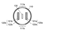
- FIG. 3 is a cross-sectional view taken along the line BB in FIG. 1.
- Sectional drawing which shows the modification of the particle counter concerning the said embodiment.
- Sectional drawing which shows another modification of the particle counting device which concerns on the said embodiment.
- FIG. 7 is a sectional view taken along arrow A′-A ′ in FIG. 6. The figure which shows an example of the detection signal by a particle counter.
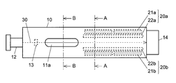
- FIGS. 1 is a top view of a particle counter according to an embodiment of the present invention
- FIG. 2 is a cross-sectional view taken along line AA in FIG. 1
- FIG. 3 is a cross-sectional view taken along line BB in FIG.
- Components that are the same as or correspond to those in FIGS. 6 and 7 described above are denoted by the same reference numerals in the last two digits as those given in FIGS. 6 and 7, and description thereof will be omitted as appropriate.
- the side where the laser light source 12 is provided in the axial direction of the housing 10 is the rear side (the base end side in the present invention), and the side where the beam stopper 14 is provided is the front (the front end side in the present invention). ).
- the particle counter according to the present embodiment is characterized in that a pair of openings 11a and 11b for allowing particles to pass through the housing 10 are provided behind the light detection units 20a and 20b. Thereby, the disturbance light which enters from the openings 11a and 11b and directly enters the light detection units 20a and 20b can be reduced, and noise derived from the disturbance light can be reduced.
- the openings 11a and 11b are arranged in the axial direction of the housing 10 so that ambient light that enters the housing 10 from the openings 11a and 11b does not directly enter the light detection units 20a and 20b. It is desirable to form it at a position sufficiently separated from the region where 20a and 20b are provided.
- Intensity I scat of the scattered light is inversely proportional to the fourth power of the wavelength ⁇ as shown by the following formula of Rayleigh scattering.
- I 0 intensity of irradiated light
- a radius of particle
- r distance from particle
- n refractive index of particle
- a laser light source 12 in the present embodiment that can emit laser light having a wavelength shorter than 500 nm (desirably about 300 to 500 nm, more preferably 400 to 500 nm).
- the intensity of the scattered light can be increased.
- the laser light with a short wavelength is irradiated, the scattered light from the particles is more strongly distributed forward (that is, the ratio of the forward scattered light to the entire scattered light is increased), and thus the light detection units 20a and 20b described above. It becomes possible to further improve the detection efficiency of the scattered light.
- the particle counter According to the particle counter according to the present embodiment, it is possible to improve the SN ratio of the detection signal and accurately count even minute particles.
- the region where the light detection units 20 a and 20 b are provided and the region where the openings 11 a and 11 b are formed do not overlap. These areas may be somewhat overlapped as long as the noise does not interfere with particle counting. In other words, it is preferable that the light detection unit can efficiently detect the forward scattered light and the opening is provided at a position where disturbance light is prevented from directly entering the light detection unit.
- the housing from the openings 11a and 11b of the disturbance light.
- a light blocking unit is provided on the optical path of the light. It is desirable to provide it.
- the light-shielding portion may include projecting portions 15 a and 15 b that are erected from the inner peripheral surface of the housing 10 toward the optical axis of the laser beam 30.
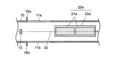
- the ambient light protrudes radially from the outer peripheral surface of the housing 10 at least at the rear end side of the periphery of the openings 11a and 11b so that the ambient light does not enter the housing 10 at a shallow angle. It is good also as a structure which provided the light-shielding part which consists of the protrusion parts 16a and 16b which do. 4 and 5 are sectional views showing a state in which the particle counter according to the present invention is cut along a plane that includes the optical axis of the laser beam 30 and is parallel to the light receiving surfaces of the photodiodes 21a and 21b.
- DESCRIPTION OF SYMBOLS 10, 110 ... Housing
Landscapes
- Chemical & Material Sciences (AREA)
- Dispersion Chemistry (AREA)
- Physics & Mathematics (AREA)
- Health & Medical Sciences (AREA)
- Life Sciences & Earth Sciences (AREA)
- Analytical Chemistry (AREA)
- Biochemistry (AREA)
- General Health & Medical Sciences (AREA)
- General Physics & Mathematics (AREA)
- Immunology (AREA)
- Pathology (AREA)
- Investigating Or Analysing Materials By Optical Means (AREA)
Abstract
筒型の筐体10と、筐体10の周面に互いに対向するように形成された一対の開口部11a、11bと、筐体10の基端側から先端側に向かって筐体10の内部にレーザ光30を照射する光源12と、筐体10内部に前記レーザ光30の光路を挟むように配置され、前記開口部11a、11bから筐体10内に進入したパーティクルにレーザ光30が照射されることで生じる散乱光を検出する一対の光検出手段20a、20bとを有するパーティクル計数装置において、前記開口部11aを、筐体10の軸方向において光検出手段20a、20bが配置されている領域よりも基端側に形成する。
Description
本発明は、例えば半導体製造装置のチャンバ内や排気管といった特定の場所を浮遊する粒子(パーティクル)の数を計測するパーティクル計数装置に関する。
半導体の処理工程で発生し、処理室内を浮遊する粉塵などのパーティクルは、製品の性能等を低下させる原因となる。そこで、半導体処理装置では、パーティクルの発生を抑えるために処理室(チャンバ)内を高真空状態にすると共に、処理室内を浮遊するパーティクルをリアルタイムで計測するパーティクル計数装置を設置している(例えば特許文献1を参照)。
従来のパーティクル計数装置の一例を図6及び図7に示す。図6はパーティクル計数装置の上面図であり、図7は図6のA’-A’矢視断面図である。該パーティクル計数装置は、円筒形の筐体110と、筐体110の周面に互いに対向するように形成された一対の開口部111a、111bと、筐体110の一端(基端)に設けられたレーザ光源112と、レーザ光を集光及び成形するためのレンズ113と、筐体110の他端(先端)に設けられたビームストッパ114と、筐体110の内部に設けられた一対の光検出部120a、120bとを含んでいる。光検出部120a、120bは、それぞれフォトダイオード121a、121bと該フォトダイオード121a、121bを保護するためのカバーガラス122a、122bを備えており、レーザ光130の光路を挟んで互いに対向するように配置されている。こうしたパーティクル計数装置において、いずれかの開口部111a、111bから筐体110の内部に進入したパーティクルは、レーザ光源112からのレーザ光130の照射により散乱光を発する。この散乱光が光検出部120a、120bに入射してフォトダイオード121a、121bにより検出され、その検出信号がコンピュータ等から成るデータ処理部(図示略)に送出されて、該データ処理部にてパーティクルの計数が行われる。
前記光検出部120a、120bによる検出信号の一例を図8に示す。パーティクル計数装置は、こうした検出信号を予め定められた閾値電圧と比較し、検出信号が閾値電圧を超えた部分をパーティクル由来の信号ピークと判定してパーティクルの計数を行う。
近年、半導体製造装置では従来に比べて微細な加工が行われるようになっており、こうした微細加工においては、これまで問題とならなかったような微小なパーティクルであっても加工精度を低下させる要因となる。そのため、近年ではパーティクル計数装置によって、ごく微小なパーティクルを検出することが求められている。パーティクルによる散乱光の強度は該パーティクルの粒径に依存するため、微小なパーティクルを検出するためには、前記閾値電圧を低く設定する必要がある。しかしながら、閾値電圧を低く設定した場合、ノイズ成分がパーティクル由来の信号ピークとして判定されてしまい、正確な計数を行うことができない場合があった。
本発明は上記の点に鑑みてなされたものであり、その目的とするところは、パーティクル計数装置において散乱光の検出信号上に現れるノイズを低減してSN比を改善し、微小なパーティクルについても検出可能とすることにある。
上記課題を解決するために成された本発明に係るパーティクル計数装置は、
a)筒型の筐体と、
b)前記筐体の周面に互いに対向するように形成された一対の開口部と、
c)前記筐体の基端側から先端側に向かって該筐体の内部にレーザ光を照射する光源と、
d)前記筐体内部に前記レーザ光の光路を挟むように配置され、前記開口部から前記筐体内に進入したパーティクルに前記レーザ光が照射されることで生じる散乱光を検出する一対の光検出手段と、
を有し、
前記一対の開口部が、前記筐体の軸方向において前記光検出手段が配置されている領域よりも基端側に形成され、前記開口部から入射する外乱光が前記光検出手段に直接入射することを低減することを特徴としている。
a)筒型の筐体と、
b)前記筐体の周面に互いに対向するように形成された一対の開口部と、
c)前記筐体の基端側から先端側に向かって該筐体の内部にレーザ光を照射する光源と、
d)前記筐体内部に前記レーザ光の光路を挟むように配置され、前記開口部から前記筐体内に進入したパーティクルに前記レーザ光が照射されることで生じる散乱光を検出する一対の光検出手段と、
を有し、
前記一対の開口部が、前記筐体の軸方向において前記光検出手段が配置されている領域よりも基端側に形成され、前記開口部から入射する外乱光が前記光検出手段に直接入射することを低減することを特徴としている。
従来のパーティクル計数装置における光検出部120a、120bには、パーティクルからの散乱光のみならず開口部111a、111bから筐体110内に進入した外乱光も入射し、これが検出信号上でノイズ成分となって微小なパーティクルの検出を妨げる要因となっていた。これに対し、上記構成から成る本発明のパーティクル計数装置では、筐体の光検出手段が配設されている領域よりも基端側(光源側)に前記一対の開口部が形成されている。このため、開口部から光検出手段に直接入射する外乱光が低減され、検出信号上に現れる外乱光由来のノイズを抑えることができる。
なお、本発明のように開口部を光検出手段よりも基端側に設けた場合、パーティクルからの散乱光のうち側方散乱光(すなわちレーザ光の光軸と略直交する方向に散乱した光)は光検出手段で受光されないこととなる。そこで、本発明に係るパーティクル計数装置では、前記レーザ光源として短波長(300~500nm程度)のレーザ光を発するものを用いることが望ましい。短波長のレーザ光をパーティクルに照射した場合には前方散乱光(パーティクルからレーザ光の進行方向に向けて散乱する光)が支配的となるため、開口部を光検出手段よりも基端側に設けた場合(すなわち開口部の前方に光検出手段を配置した場合)でも、効率よく散乱光を検出することができる。
以上で説明したように、上記本発明に係るパーティクル計数装置によれば、パーティクルからの散乱光の検出信号上に現れるノイズを低減することができ、これにより微小なパーティクルも検出可能となる。
以下、本発明を実施するための形態について図1~3を参照しつつ説明する。図1は本発明の一実施形態に係るパーティクル計数装置の上面図であり、図2は図1のA-A矢視断面図、図3は図1のB-B矢視断面図である。なお、上述の図6及び図7と同一又は対応する構成要素については、図6及び図7で付与されたものと下2桁が共通する符号を付し、適宜説明を省略する。また、以下では、筐体10の軸方向においてレーザ光源12が設けられている側を後方(本発明における基端側)とし、ビームストッパ14が設けられている側を前方(本発明における先端側)とする。
本実施形態に係るパーティクル計数装置は、パーティクルを筐体10内に通過させるための一対の開口部11a、11bが、光検出部20a、20bよりも後方に設けられていることを特徴としている。これにより、開口部11a、11bから入射して光検出部20a、20bに直接入射する外乱光を軽減し、該外乱光由来のノイズを低減することができる。
なお、開口部11a、11bから筐体10内に入射した外乱光が光検出部20a、20bに直接入射することがないよう、開口部11a、11bは、筐体10の軸方向において光検出部20a、20bが設けられている領域から十分に離間した位置に形成することが望ましい。
散乱光の強度Iscatは以下のレイリー散乱の式で示されるように波長λの4乗に反比例する。

従って、本実施形態におけるレーザ光源12としては500nmよりも短波長(望ましくは300~500nm程度、さらに好ましくは400~500nm)のレーザ光を出射できるものを使用することが望ましい。これにより、パーティクルの粒子径が小さい場合でも散乱光の強度を大きくすることができる。また、短波長のレーザ光を照射した場合、パーティクルからの散乱光はより前方に強く分布する(すなわち散乱光全体に占める前方散乱光の割合が大きくなる)ため、上記の光検出部20a、20bによる散乱光の検出効率を一層高めることが可能となる。
以上により、本実施形態に係るパーティクル計数装置によれば、検出信号のSN比を改善し、微小なパーティクルについても正確に計数することが可能となる。
なお、図1では、筐体10の軸方向において、光検出部20a、20bが設けられている領域と開口部11a、11bが形成されている領域とが重複しない構成としたが、外乱光由来のノイズがパーティクル計数の妨げとならない範囲でこれらの領域が多少重複していてもよい。つまり、光検出部が効率よく前方散乱光を検出でき、かつ、外乱光が直接光検出部に入射することを低減する位置に開口部が設けられるとよい。
また、光検出部20a、20bが設けられている領域と開口部11a、11bが形成されている領域とが近接している場合には、前記外乱光の内、開口部11a、11bから筐体10の内部に浅い角度(すなわちレーザ光30の光軸と平行に近い角度)で進入して光検出部20a、20bへと直接入射する光を遮るために、該光の光路上に遮光部を設けることが望ましい。該遮光部は例えば、図4に示すように、筐体10の内周面からレーザ光30の光軸に向かって立設された突出部15a、15bから成るものとすることができる。あるいは、前記外乱光が筐体10の内部に浅い角度で入射しないよう、図5に示すように、開口部11a、11bの周縁の少なくとも後端側において筐体10の外周面から径方向に突出する突出部16a、16bから成る遮光部を設けた構成としてもよい。なお、図4、5はいずれも本発明に係るパーティクル計数装置をレーザ光30の光軸を含み且つフォトダイオード21a、21bの受光面に平行な面で切断した状態を示す断面図である。
10、110…筐体
11a、11b、111a、111b…開口部
12、112…レーザ光源
13、113…レンズ
14、114…ビームストッパ
20a、20b、120a、120b…光検出部
21a、21b、121a、121b…フォトダイオード
22a、22b、122a、122b…カバーガラス
30、130…レーザ光
11a、11b、111a、111b…開口部
12、112…レーザ光源
13、113…レンズ
14、114…ビームストッパ
20a、20b、120a、120b…光検出部
21a、21b、121a、121b…フォトダイオード
22a、22b、122a、122b…カバーガラス
30、130…レーザ光
Claims (5)
- a)筒型の筐体と、
b)前記筐体の周面に互いに対向するように形成された一対の開口部と、
c)前記筐体の基端側から先端側に向かって該筐体の内部にレーザ光を照射する光源と、
d)前記筐体内部に前記レーザ光の光路を挟むように配置され、前記開口部から前記筐体内に進入したパーティクルに前記レーザ光が照射されることで生じる散乱光を検出する一対の光検出手段と、
を有し、
前記一対の開口部が、前記筐体の軸方向の前記光検出手段が配置されている領域よりも基端側に形成され、前記開口部から入射する外乱光が前記光検出手段に直接入射するのを低減することを特徴とするパーティクル計数装置。 - 前記パーティクルに前記レーザ光が照射されることで生じる散乱光が前記レーザ光の進行方向に強く分布するように、前記レーザ光が500nmよりも短波長であることを特徴とする請求項1に記載のパーティクル計数装置。
- 前記レーザ光の波長が300~500nmであることを特徴とする請求項1又は2に記載のパーティクル計数装置。
- 前記筐体の軸方向において、前記開口部が形成されている領域が、前記光検出手段が配置されている領域と重複していないことを特徴とする請求項1~3のいずれかに記載のパーティクル計数装置。
- 前記筐体の軸方向において、前記開口部が形成されている領域と前記光検出手段が配置されている領域とが近接しており、
前記筐体が、前記開口部からの外乱光の前記光検出手段への直接入射を遮るための遮光部を有することを特徴とする請求項1~4のいずれかに記載のパーティクル計数装置。
Applications Claiming Priority (2)
| Application Number | Priority Date | Filing Date | Title |
|---|---|---|---|
| JP2014-062068 | 2014-03-25 | ||
| JP2014062068 | 2014-03-25 |
Publications (1)
| Publication Number | Publication Date |
|---|---|
| WO2015146429A1 true WO2015146429A1 (ja) | 2015-10-01 |
Family
ID=54194963
Family Applications (1)
| Application Number | Title | Priority Date | Filing Date |
|---|---|---|---|
| PCT/JP2015/055235 Ceased WO2015146429A1 (ja) | 2014-03-25 | 2015-02-24 | パーティクル計数装置 |
Country Status (1)
| Country | Link |
|---|---|
| WO (1) | WO2015146429A1 (ja) |
Cited By (1)
| Publication number | Priority date | Publication date | Assignee | Title |
|---|---|---|---|---|
| JP2020176915A (ja) * | 2019-04-18 | 2020-10-29 | 株式会社島津製作所 | パーティクル計数方法及びパーティクル計数装置 |
Citations (6)
| Publication number | Priority date | Publication date | Assignee | Title |
|---|---|---|---|---|
| JPS61272635A (ja) * | 1985-05-29 | 1986-12-02 | Nippon Kagaku Kogyo Kk | 微粒子計数装置 |
| JPH0283450U (ja) * | 1988-12-15 | 1990-06-28 | ||
| JPH0344539A (ja) * | 1989-07-13 | 1991-02-26 | Anelva Corp | 真空内ダスト監視装置 |
| JP2003098083A (ja) * | 2001-09-25 | 2003-04-03 | Matsushita Electric Works Ltd | 浮遊微粒子検知装置 |
| JP2006511822A (ja) * | 2002-12-18 | 2006-04-06 | ハンブルガー,ロベルト,エヌ. | 空中浮遊病原体検出システム及び方法 |
| JP2010534830A (ja) * | 2007-07-26 | 2010-11-11 | マルバーン インストゥルメンツ リミテッド | 光学的測定装置のための光線出力装置、光線出力方法、及び光散乱式測定器 |
-
2015
- 2015-02-24 WO PCT/JP2015/055235 patent/WO2015146429A1/ja not_active Ceased
Patent Citations (6)
| Publication number | Priority date | Publication date | Assignee | Title |
|---|---|---|---|---|
| JPS61272635A (ja) * | 1985-05-29 | 1986-12-02 | Nippon Kagaku Kogyo Kk | 微粒子計数装置 |
| JPH0283450U (ja) * | 1988-12-15 | 1990-06-28 | ||
| JPH0344539A (ja) * | 1989-07-13 | 1991-02-26 | Anelva Corp | 真空内ダスト監視装置 |
| JP2003098083A (ja) * | 2001-09-25 | 2003-04-03 | Matsushita Electric Works Ltd | 浮遊微粒子検知装置 |
| JP2006511822A (ja) * | 2002-12-18 | 2006-04-06 | ハンブルガー,ロベルト,エヌ. | 空中浮遊病原体検出システム及び方法 |
| JP2010534830A (ja) * | 2007-07-26 | 2010-11-11 | マルバーン インストゥルメンツ リミテッド | 光学的測定装置のための光線出力装置、光線出力方法、及び光散乱式測定器 |
Cited By (2)
| Publication number | Priority date | Publication date | Assignee | Title |
|---|---|---|---|---|
| JP2020176915A (ja) * | 2019-04-18 | 2020-10-29 | 株式会社島津製作所 | パーティクル計数方法及びパーティクル計数装置 |
| JP7115406B2 (ja) | 2019-04-18 | 2022-08-09 | 株式会社島津製作所 | パーティクル計数方法及びパーティクル計数装置 |
Similar Documents
| Publication | Publication Date | Title |
|---|---|---|
| US10670522B2 (en) | Micro object detection apparatus | |
| US9857287B2 (en) | Particulate sensor device | |
| US8705030B2 (en) | Optical sample detection system and sample analysis device | |
| KR101529127B1 (ko) | 광전식 연기 감지기 | |
| JP6562647B2 (ja) | 赤外線温度計およびエネルギーゾーンの温度測定方法 | |
| JP5671873B2 (ja) | レーザ溶接モニタリング装置 | |
| KR101919103B1 (ko) | 반사경을 구비하지 않는 광학식 미생물 검출 장치 | |
| WO2015146429A1 (ja) | パーティクル計数装置 | |
| KR20160060845A (ko) | 광학식 센서를 위한 광학계 및 이를 포함하는 센서 | |
| KR101513542B1 (ko) | 광학계 | |
| JP7507384B2 (ja) | エアロゾル計測装置及びエアロゾル計測方法 | |
| KR20160114445A (ko) | 라이다 시스템 | |
| US8472021B2 (en) | Particle detector | |
| WO2021235127A1 (ja) | 熱輻射光検出装置及びレーザ加工装置 | |
| JP6129014B2 (ja) | 蛍光検出装置および蛍光検出方法 | |
| JP2004219131A (ja) | オイルミスト検出装置 | |
| JPS6335395Y2 (ja) | ||
| WO2016035300A1 (ja) | 粒子検出センサ | |
| JP6330900B2 (ja) | 分光測定装置及び積分球 | |
| JP2015227858A5 (ja) | ||
| JP2015191462A (ja) | 煙感知器 | |
| KR101855554B1 (ko) | 광학식 센서를 위한 광학계 및 이를 포함하는 포토 센서 | |
| KR20180041513A (ko) | 동축 흡입팬 방식의 입자 측정 장치 | |
| JP2015191466A (ja) | 煙感知器 | |
| JPH07146115A (ja) | 光センサ |
Legal Events
| Date | Code | Title | Description |
|---|---|---|---|
| 121 | Ep: the epo has been informed by wipo that ep was designated in this application |
Ref document number: 15769304 Country of ref document: EP Kind code of ref document: A1 |
|
| NENP | Non-entry into the national phase |
Ref country code: DE |
|
| 122 | Ep: pct application non-entry in european phase |
Ref document number: 15769304 Country of ref document: EP Kind code of ref document: A1 |
|
| NENP | Non-entry into the national phase |
Ref country code: JP |