WO2015146400A1 - 携帯機器用カバー - Google Patents
携帯機器用カバー Download PDFInfo
- Publication number
- WO2015146400A1 WO2015146400A1 PCT/JP2015/054868 JP2015054868W WO2015146400A1 WO 2015146400 A1 WO2015146400 A1 WO 2015146400A1 JP 2015054868 W JP2015054868 W JP 2015054868W WO 2015146400 A1 WO2015146400 A1 WO 2015146400A1
- Authority
- WO
- WIPO (PCT)
- Prior art keywords
- cover
- portable device
- smartphone
- unit
- connector
- Prior art date
- Legal status (The legal status is an assumption and is not a legal conclusion. Google has not performed a legal analysis and makes no representation as to the accuracy of the status listed.)
- Ceased
Links
Images




Classifications
-
- H—ELECTRICITY
- H04—ELECTRIC COMMUNICATION TECHNIQUE
- H04B—TRANSMISSION
- H04B1/00—Details of transmission systems, not covered by a single one of groups H04B3/00 - H04B13/00; Details of transmission systems not characterised by the medium used for transmission
- H04B1/38—Transceivers, i.e. devices in which transmitter and receiver form a structural unit and in which at least one part is used for functions of transmitting and receiving
- H04B1/3827—Portable transceivers
- H04B1/3888—Arrangements for carrying or protecting transceivers
-
- G—PHYSICS
- G07—CHECKING-DEVICES
- G07C—TIME OR ATTENDANCE REGISTERS; REGISTERING OR INDICATING THE WORKING OF MACHINES; GENERATING RANDOM NUMBERS; VOTING OR LOTTERY APPARATUS; ARRANGEMENTS, SYSTEMS OR APPARATUS FOR CHECKING NOT PROVIDED FOR ELSEWHERE
- G07C9/00—Individual registration on entry or exit
- G07C9/00174—Electronically operated locks; Circuits therefor; Nonmechanical keys therefor, e.g. passive or active electrical keys or other data carriers without mechanical keys
-
- H—ELECTRICITY
- H04—ELECTRIC COMMUNICATION TECHNIQUE
- H04M—TELEPHONIC COMMUNICATION
- H04M1/00—Substation equipment, e.g. for use by subscribers
- H04M1/02—Constructional features of telephone sets
- H04M1/18—Telephone sets specially adapted for use in ships, mines, or other places exposed to adverse environment
- H04M1/185—Improving the shock resistance of the housing, e.g. by increasing the rigidity
-
- H—ELECTRICITY
- H04—ELECTRIC COMMUNICATION TECHNIQUE
- H04M—TELEPHONIC COMMUNICATION
- H04M1/00—Substation equipment, e.g. for use by subscribers
- H04M1/72—Mobile telephones; Cordless telephones, i.e. devices for establishing wireless links to base stations without route selection
- H04M1/724—User interfaces specially adapted for cordless or mobile telephones
- H04M1/72403—User interfaces specially adapted for cordless or mobile telephones with means for local support of applications that increase the functionality
- H04M1/72409—User interfaces specially adapted for cordless or mobile telephones with means for local support of applications that increase the functionality by interfacing with external accessories
- H04M1/724092—Interfacing with an external cover providing additional functionalities
-
- H—ELECTRICITY
- H04—ELECTRIC COMMUNICATION TECHNIQUE
- H04M—TELEPHONIC COMMUNICATION
- H04M1/00—Substation equipment, e.g. for use by subscribers
- H04M1/72—Mobile telephones; Cordless telephones, i.e. devices for establishing wireless links to base stations without route selection
- H04M1/724—User interfaces specially adapted for cordless or mobile telephones
- H04M1/72448—User interfaces specially adapted for cordless or mobile telephones with means for adapting the functionality of the device according to specific conditions
- H04M1/72454—User interfaces specially adapted for cordless or mobile telephones with means for adapting the functionality of the device according to specific conditions according to context-related or environment-related conditions
-
- H—ELECTRICITY
- H04—ELECTRIC COMMUNICATION TECHNIQUE
- H04Q—SELECTING
- H04Q9/00—Arrangements in telecontrol or telemetry systems for selectively calling a substation from a main station, in which substation desired apparatus is selected for applying a control signal thereto or for obtaining measured values therefrom
-
- H—ELECTRICITY
- H04—ELECTRIC COMMUNICATION TECHNIQUE
- H04M—TELEPHONIC COMMUNICATION
- H04M1/00—Substation equipment, e.g. for use by subscribers
- H04M1/72—Mobile telephones; Cordless telephones, i.e. devices for establishing wireless links to base stations without route selection
- H04M1/724—User interfaces specially adapted for cordless or mobile telephones
- H04M1/72403—User interfaces specially adapted for cordless or mobile telephones with means for local support of applications that increase the functionality
- H04M1/72409—User interfaces specially adapted for cordless or mobile telephones with means for local support of applications that increase the functionality by interfacing with external accessories
- H04M1/72415—User interfaces specially adapted for cordless or mobile telephones with means for local support of applications that increase the functionality by interfacing with external accessories for remote control of appliances
-
- H—ELECTRICITY
- H04—ELECTRIC COMMUNICATION TECHNIQUE
- H04M—TELEPHONIC COMMUNICATION
- H04M1/00—Substation equipment, e.g. for use by subscribers
- H04M1/72—Mobile telephones; Cordless telephones, i.e. devices for establishing wireless links to base stations without route selection
- H04M1/724—User interfaces specially adapted for cordless or mobile telephones
- H04M1/72448—User interfaces specially adapted for cordless or mobile telephones with means for adapting the functionality of the device according to specific conditions
- H04M1/7246—User interfaces specially adapted for cordless or mobile telephones with means for adapting the functionality of the device according to specific conditions by connection of exchangeable housing parts
Definitions
- the present invention relates to a cover used for portable devices such as smartphones (mobile phones) and tablets, and more particularly to a cover for portable devices having a keyless operation function of a vehicle such as a keyless entry function.
- Patent Document 1 proposes a system in which a center performs communication with a vehicle-mounted device based on an operation of a mobile phone, and performs various operations of a vehicle unlocking key and a vehicle-mounted device.
- Patent Document 2 proposes a mobile phone in which a transmitter and a control circuit for unlocking keys are incorporated in the mobile phone itself, and a signal is directly transmitted from the mobile phone to the vehicle according to the operation of the mobile phone to perform the unlocking key. ing.
- JP 2013-121735 A Japanese Patent Laid-Open No. 10-317753
- the present invention has been made in view of the above circumstances, and allows a portable device to have a keyless operation function with a simple and inexpensive configuration and without hindering the user's freedom of selection of the portable device.
- An object of the present invention is to provide a portable device cover that can be prevented from being erroneously operated.
- the cover for portable devices of the present invention comprises a cover main body to be attached to the portable device, an operation unit provided in the cover main body and capable of receiving an operation from the outside, and the operation unit receiving the operation.
- a transmission unit that transmits an operation signal for remotely operating the in-vehicle device, a determination unit that determines whether or not the portable device is in a specific state, and a determination unit that determines that the determination unit is in the specific state
- a restricting means for executing processing for restricting the remote operation.
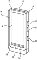
- FIG. 1 is a perspective view of a smartphone cover that is a portable device cover according to the present invention
- FIG. 2 is a perspective view of a smartphone to which the smartphone cover is attached.
- the smartphone cover is described based on the states shown in FIGS. 1 and 2.
- the smartphone cover 1A (hereinafter abbreviated as cover 1A) has a rectangular cover body 10 that is flat in the front-rear direction.
- the cover body 10 includes a plate-like back surface portion 12 that is elongated in the vertical direction and a peripheral wall portion 14 that is connected to the periphery of the back surface portion 12.
- the back surface portion 12 and the peripheral wall portion 14 are integrally formed of the same resin material.
- the inside of the surrounding wall part 14 of this cover main body 10 is made into the accommodating part 11 of the smart phone 2, and the cover 1A is mounted
- the smartphone 2 has a rectangular parallelepiped shape that is flat in the front-rear direction, and includes a rectangular display unit 4 formed of a touch panel on the front surface and three selection keys 5a to 5c arranged in a row on the left and right sides.
- the front surface portion on which the display unit 4 and the selection keys 5a to 5c are provided is the main surface of the smartphone 2, and the smartphone 2 is accommodated in the accommodating portion 11 so that the main surface faces the outside from the opening of the accommodating portion 11. .
- the smart phone side connector (equipment side of this invention) which consists of a female connector provided with the terminal for battery charging and the terminal for communication with external devices (personal computer etc.) Corresponding to the first connector).
- the peripheral wall portion 14 of the cover body 10 has a shape corresponding to the outline of the smartphone 2, and the peripheral wall portion 14 includes an upper side portion 14 a that fits to the upper side surface, the lower side surface, the left side surface, and the right side surface of the smartphone 2. It includes a lower side portion 14b, a left side portion 14c, and a right side portion 14d.
- buttons 16 to 18 are provided on the right side portion 14d (corresponding to the cover side surface portion of the present invention).
- a lock button 16 for bringing the door lock mechanism of the vehicle into a locked state an unlock button 17 for bringing the door lock mechanism into an unlocked state
- an engine start button 18 for starting the engine. are provided in order from the top.
- These buttons 16 to 18 are all press-type, and are provided so that the user can easily press the smartphone 2 with the cover 1A (hereinafter simply referred to as the smartphone 2) with the thumb while holding the smartphone 2 with the right hand. It has been.
- the lower side portion 14 b includes a control board 20 that transmits an operation signal corresponding to the operation of the buttons 16 to 18, that is, a signal for controlling the door lock mechanism and the engine. Has been.
- the control board 20 is provided with a board-side connector 22 (corresponding to the cover-side first connector of the present invention) for electrically connecting the control board 20 and the smartphone 2.
- the board-side connector 22 is a male connector mounted on the control board 20 and protrudes into the housing part 11 from the inner wall surface of the lower side part 14 b of the cover body 10.
- the board-side connector 22 is fitted into the smartphone-side connector, whereby the control board 20 and the control board 40 on the smartphone 2 side (shown in FIG. 3) are electrically connected. It has become so.
- symbol 12a in FIG. 1 is a camera opening part for opening the camera lens provided in the back surface of the smart phone 2
- symbol 24 is a battery which is a power supply of the control board 20.
- FIG. Although illustration is omitted, a detachable lid portion is provided on the back surface of the cover 1A (the outer surface of the back surface portion 12 of the cover body 10), and the battery can be replaced by removing this lid body. Yes.
- FIG. 3 is a block diagram showing the electrical configuration of the cover 1A. As shown in the figure, the buttons 16 to 18 and the battery 24 are all electrically connected to the control board 20.
- a microcomputer or the like is mounted on the control board 20, and the control device 20 includes a transmission circuit 31 having an antenna 32, a determination circuit 33, an I / F (interface) circuit 34, and the like as main functional configurations. .
- the transmission circuit 31 (corresponding to the transmission unit of the present invention) transmits an operation signal for controlling the door lock mechanism and the engine to the vehicle in response to the pressing operation of each of the buttons 16-18.
- the operation signal includes a self-authentication signal, and the vehicle responds to the pressed buttons 16 to 18 when the authentication number attached to the self-authentication signal matches a pre-registered number.
- the door lock mechanism is switched to the locked state or the unlocked state, and the engine (starter) is started.
- the determination circuit 33 (corresponding to the determination unit of the present invention) regulates the transmission of the operation signal by the transmission circuit 31 according to the usage state of the smartphone 2. In this example, the determination circuit 33 determines whether or not the buttons 16 to 18 are upward (the right side of the smartphone 2 is upward). When the buttons 16 to 18 are other than upward, the determination circuit 33 is used for operation by the transmission circuit 31. Regulate signal transmission. That is, in this example, the determination circuit 33 also functions as a regulation unit of the present invention.
- the control board 40 built in the smartphone 2 is equipped with an inclination sensor 42 that detects the attitude of the smartphone 2, and the determination circuit 33 includes the I / F circuits 34 and 43 of the boards 20 and 40.
- the posture information output by the tilt sensor 42 is acquired via the button, and it is determined whether or not each of the buttons 16 to 18 is upward based on the posture information.
- Such a function is realized by preliminarily storing application software (application) for allowing the determination circuit 33 to acquire posture information in the smartphone 2.
- application application
- the posture information detected by the tilt sensor 42 is transmitted from the control board 40 on the smartphone 2 side to the control board 20 on the cover 1A side.
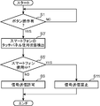
- the determination circuit 33 waits for any of the buttons 16 to 18 to be pressed, and when any of the buttons is operated (YES in step S1), the tilt sensor The posture information detected by 42 is acquired from the smartphone 2 side (step S3).
- step S5 it is determined whether or not the buttons 16 to 18 are upward. If YES is determined here, the determination circuit 33 outputs a permission signal to the transmission circuit 31, and causes the transmission circuit 31 to transmit an operation signal corresponding to the button that has been pressed among the buttons 16 to 18 (step S9). ). This is the end of this flowchart.
- step S5 when NO is determined in step S5, that is, when it is determined that the buttons 16 to 18 are not upward, the determination circuit 33 outputs a prohibition signal to the transmission circuit 31, and the transmission circuit 31 transmits the operation signal. Is prohibited (step S11). Thereby, this flowchart is ended without causing the transmission circuit 31 to transmit the operation signal.
- the smartphone 2 can be provided with a keyless function of locking / unlocking the door lock mechanism and starting the engine simply by attaching the cover 1A to the smartphone 2a. Therefore, the smartphone 2 can be provided with the keyless operation function as described above with a simple and inexpensive configuration and without inhibiting the user's freedom of selection of the smartphone 2.
- the cover 1A when the buttons 16 to 18 are not in the upward state (the right side of the smartphone 2 is upward), the operation from the transmission circuit 31 is performed even if the buttons 16 to 18 are pressed.
- the door lock mechanism or the engine may not be operated unintentionally during the operation of the smartphone 2, for example, during mail operation, Internet site browsing, or telephone call. Can be prevented. That is, in many cases, the display unit 4 is normally facing upward during mail operations or browsing the Internet, and the smartphone 2 is in a standing posture (the posture shown in FIG. 2) during a call.
- the door lock mechanism or the like is not intended during the operation of the smartphone 2. It is possible to prevent operation.
- the determination circuit 33 acquires posture information detected by the tilt sensor 42 built in the smartphone 2, and determines whether the buttons 16 to 18 are upward based on the posture information. Therefore, there is an advantage that the malfunction as described above during use of the smartphone 2 can be prevented with a rational configuration using the function of the smartphone 2. That is, since the smartphone 2 is equipped with an inclination sensor so that the smartphone 2 can be used as an operation tool for games or the like, the cover 1A has a rational configuration using such an inclination sensor. Become.
- the cover 1A described above determines whether or not the buttons 16 to 18 are facing upward based on the posture information detected by the tilt sensor 42 (steps S3 and S5 in FIG. 4). Instead, as shown in FIG. 5, it may be determined more directly whether the smartphone 2 is in use (steps S3 ′ and S5 ′). Specifically, the display unit 4 of the smartphone 2 detects a position by detecting a change in surface charge of a portion touched by an operator, for example, an electrostatic field is formed on a capacitive touch panel, that is, a panel surface. In the case of a touch panel, the touch panel position detection information is acquired by the determination circuit 33.
- the determination circuit 33 determines whether or not the smartphone 2 is in use, and prohibits transmission of the operation signal by the transmission circuit 31 if it is in use. According to such a configuration, whether or not the smartphone 2 is in use can be determined more directly, so that the door lock mechanism and the like can be more reliably prevented from being operated unintentionally while the smartphone 2 is being used. Is possible.
- step S5 ′ in addition to performing the process of step S5 ′ alone, the process of step S5 ′ and the process of step S5 of FIG. 4 may be used in combination. That is, when the smartphone 2 is not in use or when the buttons 16 to 18 are not upward, the transmission of the operation signal by the transmission circuit 31 may be prohibited. According to this configuration, it is possible to more reliably prevent the malfunction as described above during use of the smartphone 2.
- application software for allowing the determination circuit 33 to acquire the touch panel position detection information is stored in the smartphone 2 in advance, so that the touch panel position detection information is transferred to the control board of the smartphone 2. It can be transmitted to the control board 20 of the cover 1A from the 40 side.
- FIG. 6 is a block diagram showing an electrical configuration of a smartphone cover 1B (hereinafter abbreviated as cover 1B) according to the second embodiment.
- cover 1B The basic configuration of the cover 1B of the second embodiment is the same as the cover 1A of the first embodiment except for the following points.
- the board 1 side connector 22 for connecting the cover 1B (control board 20) and the smartphone 2 is not provided on the control board 20 of the cover 1B of the second embodiment. Electrically completely independent.
- the control board 20 is not provided with the I / F circuit 34, but is provided with an inclination sensor 36 instead.
- the tilt sensor 36 is equivalent to the tilt sensor 42 mounted on the smartphone 2.
- the determination circuit 33 determines whether or not the buttons 16 to 18 are upward based on the posture information detected by the tilt sensor 36 mounted on the control board 20. Based on the determination result, the transmission of the operation signal by the transmission circuit 31 is restricted.
- the transmission control of the operation signal by the cover 1B (control board 20) in this case is basically the same as the control shown in FIG. 4 except that the posture information is acquired from the smartphone 2 side.
- the smartphone 2 can have a keyless operation function such as a door lock mechanism just by being attached to the smartphone 2, Moreover, the above malfunctions during use of the smartphone 2 can be prevented.
- the cover 1B of the second embodiment is completely independent of the smartphone 2 electrically, so that any one of the applications (application software) is present. Even when the smartphone 2 is worn, the above-described effects can be enjoyed.
- smart phone cover 1A, 1B of 1st, 2nd embodiment demonstrated above is an illustration of preferable embodiment of the cover for portable devices which concerns on this invention, Comprising:
- the specific structure is the summary of this invention. Changes can be made as appropriate without departing from the scope.
- a prohibition signal is output from the determination circuit 33 to the transmission circuit 31, thereby transmitting.
- the transmission of the operation signal from the circuit 31 is restricted (prohibited) (step S11)
- the signal transmission from the transmission circuit 31 is prevented by locking the pressing operation of each button 16-18. It may be regulated (prohibited).
- step S11 in addition to restricting (prohibiting) transmission of the operation signal from the transmission circuit 31, for example, predetermined signal processing is performed on the operation signal, for example, authentication included in the operation signal
- the operation of the door lock mechanism may be substantially restricted by causing the transmission circuit 31 to transmit an operation signal after performing signal processing so that the number cannot be recognized. Even in such a configuration, it is possible to prevent the door lock mechanism and the like from being operated unintentionally while the smartphone 2 is being used.
- the battery 24 is provided as a power source for the control board 20, but the battery of the smartphone 2 may be shared as the power source for the control board 20.
- a terminal that can be connected to the battery charging terminal of the smartphone-side connector may be provided in the board-side connector 22 so that the control board 20 receives power supply from the battery on the smartphone 2 side.
- the battery 24 of the cover 1A is not necessary, so that the configuration of the cover 1A can be simplified.
- the smartphone-side connector functions as the device-side second connector of the present invention
- the board-side connector 22 functions as the cover-side second connector.
- the board-side connector 22 for connecting the cover 1A (control board 20) and the smartphone 2 is provided on the lower side part 14b of the cover body 10 (peripheral wall part 14).
- the position of the side connector 22 can be appropriately changed according to the position of the smartphone-side connector.
- the covers 1A and 1B are provided with a lock button 16 and an unlock button 17 of the door lock mechanism and an engine start button 18 as keyless operation buttons.
- the types of buttons for the keyless operation are as follows. It can be changed as appropriate. For example, you may make it further provide the button for starting an air-conditioner as a vehicle-mounted apparatus.
- buttons 16 to 18 provided on the covers 1A and 1B may be of a slide type other than the press type as in the embodiment.
- the covers 1A and 1B are intended for right-handed users, so that the user who is using the smartphone 2 can directly operate the lock button 16, the unlock button 17, and the engine start button 18 with the thumb. Further, the buttons 16 to 18 are provided on the right side portion 14d of the cover body 10. However, the lock button 16, the unlock button 17, and the engine start button 18 may be provided on the left side portion 14c of the cover body 10 assuming a left-handed user.
- a smartphone cover has been described as an example of the portable device cover of the present invention.
- the present invention can also be applied to a cover of a smart device other than a smartphone, such as a tablet, or other portable devices. .
- the portable device cover includes a cover main body to be attached to the mobile device, an operation unit that is provided in the cover main body and can be operated from the outside, and the operation unit receives the operation.
- a transmission unit that transmits an operation signal for remotely operating the in-vehicle device, a determination unit that determines whether or not the portable device is in a specific state, and a determination unit that determines that the determination unit is in the specific state
- a restricting means for executing processing for restricting the remote operation.
- a cover for a mobile device such as a keyless entry function (a function of performing keying / unlocking operation of a vehicle keylessly) just by being attached to a mobile device such as a smartphone (mobile phone) or a tablet. It becomes possible to give the portable device a keyless operation function.
- the process for restricting the remote operation is executed, so that it is possible to prevent the in-vehicle device from being operated unintentionally in the specific state. .
- the restriction means restricts transmission of the operation signal by the transmission unit, or processes the operation signal transmitted by the transmission unit so that the remote operation is restricted. It is.
- the mobile device cover is attached to a mobile device including a device-side first connector capable of outputting information indicating the usage state of the mobile device to the outside
- the cover body includes: A cover-side first connector connected to the device-side first connector is provided, and the determination unit acquires information indicating the use state from the portable device via the connectors, and the portable device It is determined that the specific state is in use.
- the determination unit when the portable device includes an inclination sensor that detects the posture, and the posture information detected by the tilt sensor can be output to the outside as information indicating the use state, the determination unit The posture information output from the tilt sensor can be acquired, and based on the posture information, it can be configured to determine when the operation unit is other than upward as the specific state.
- the portable device cover includes an inclination sensor that is provided in the cover main body and detects the posture of the portable device, and the determination unit includes posture information of the portable device that is detected by the inclination sensor. Based on the above, it may be determined that the specific state is when the operation unit is other than upward.
- the in-vehicle device is operated only when the operation unit is facing upward.
- it is not necessary to acquire posture information from the portable device, and thus the degree of freedom of the portable device that can be attached is further increased. Further improvement.
- the cover body is connected to the device-side second connector.
- the cover side second connector to be operated may be provided, and the transmission unit, the determination unit, and the regulating unit may be operated by obtaining electric power from the portable device.
- the vehicle-mounted device can be operated keylessly without providing a power source for the portable device cover itself.
- the cover main body has a cover side surface portion that covers a side surface portion around the main surface on which the display portion of the smartphone or the tab red is provided, from the outside,
- the operation unit is preferably provided on the side surface of the cover.
- the smartphone or the like can be provided with a keyless operation function without hindering the operability of the smartphone or tab red.
Landscapes
- Engineering & Computer Science (AREA)
- Signal Processing (AREA)
- Computer Networks & Wireless Communication (AREA)
- Human Computer Interaction (AREA)
- Environmental & Geological Engineering (AREA)
- Physics & Mathematics (AREA)
- General Physics & Mathematics (AREA)
- Telephone Set Structure (AREA)
- Selective Calling Equipment (AREA)
- Lock And Its Accessories (AREA)
Abstract
携帯機器用カバーは、携帯機器に装着されるカバー本体と、このカバー本体に備えられて外部から操作を受けることが可能な操作部と、この操作部が操作を受けることにより、車載装置を遠隔操作するための操作用信号を送信する送信部と、前記携帯機器が特定状態にあるか否かを判定する判定部と、前記判定部が前記特定状態にあると判定したときに、前記遠隔操作を規制するための処理を実行する規制手段とを含む。
Description
本発明は、スマートフォン(携帯電話)やタブレット等の携帯機器に用いられるカバーであって、特に、キーレスエントリ機能などの車両のキーレス操作機能を備えた携帯機器用カバーに関する。
いわゆるキーレスエントリシステムとして、近年、キーホルダやキーの代わりに、携帯電話の操作により車両の解施鍵等を可能とするシステムが各種提案されている。例えば、特許文献1には、携帯電話の操作に基づいてセンターが車載機器と通信を行うことにより、車両の解施鍵や車載装置の各種操作を行うシステムが提案されている。また、特許文献2には、解施鍵用の送信機や制御回路を携帯電話自体に組み込み、携帯電話の操作に応じて当該携帯電話から車両に直接信号を送信して解施鍵を行う携帯電話機が提案されている。
しかし、特許文献1のような携帯電話の通信回線を利用したシステムでは、開発費用が嵩み、また通信費用等も発生するためシステムの安価な提供が難しい。また、特許文献2の場合には、携帯電話機自体を新たなに開発する必要があるばかりでなく、携帯電話が車両に対応した専用機となるため、使用者の携帯電話選択の自由度が狭くなる等の問題がある。そこで、最近では、携帯電話のカバー(特にスマートフォンのカバー)に解施鍵用の送信機や操作ボタンを搭載することで、キーレスエントリ機能を実質的に携帯電話に持たせることが考えられている。これによれば、簡単かつ安価な構成で、しかも使用者の携帯電話選択の自由度を阻害することなく、キーレスエントリ機能を携帯電話に持たせることが可能となる。
ところが、このように携帯電話のカバーに解施鍵用の送信機や操作ボタンを搭載する場合、カバーに設けられた操作ボタンが携帯電話の操作中に意図せず押されて車両の解施鍵が行われる等、誤操作が発生することが考えられる。従って、このような誤操作を防止することが必要となる。
本発明は、上記の事情に鑑みてなされたものであり、簡単かつ安価な構成で、また使用者の携帯機器の選択の自由度を阻害することなくキーレス操作機能を携帯機器に持たせることができ、しかも、誤操作を防止可能な携帯機器用カバーを提供することを目的とする。
そして、本発明の携帯機器用カバーは、携帯機器に装着されるカバー本体と、このカバー本体に備えられて外部から操作を受けることが可能な操作部と、この操作部が操作を受けることにより、車載装置を遠隔操作するための操作用信号を送信する送信部と、前記携帯機器が特定状態にあるか否かを判定する判定部と、前記判定部が前記特定状態にあると判定したときに、前記遠隔操作を規制するための処理を実行する規制手段と、を含むものである。
以下、添付図面を参照しながら本発明の好ましい実施の一形態について詳述する。
(第1の実施形態)
図1は、本発明に係る携帯機器用カバーであるスマートフォンカバーを斜視図で示しており、図2は、スマートフォンカバーが装着されたスマートフォンを斜視図で示している。なお、以下の説明では、図1及び図2に示す状態に基づいて、スマートフォンカバーの説明を行うものとする。
図1は、本発明に係る携帯機器用カバーであるスマートフォンカバーを斜視図で示しており、図2は、スマートフォンカバーが装着されたスマートフォンを斜視図で示している。なお、以下の説明では、図1及び図2に示す状態に基づいて、スマートフォンカバーの説明を行うものとする。
図1に示すように、スマートフォンカバー1A(以下、カバー1Aと略す)は、前後方向に偏平な長方形状のカバー本体10を有する。このカバー本体10は、上下方向に細長い板状の背面部12とこの背面部12の周囲に繋がる周壁部14とを備える。これら背面部12と周壁部14とは同一の樹脂材料により一体に形成されている。そして、このカバー本体10の周壁部14の内側がスマートフォン2の収容部11とされ、図2に示すように、当該収容部11にスマートフォン2が嵌め込まれることで、カバー1Aがスマートフォン2に装着されるようになっている。
スマートフォン2は、前後方向に偏平な直方体形状であり、前面部に、タッチパネルからなる長方形の表示部4とその下側に左右一列に並ぶ3つの選択キー5a~5cとを備えている。表示部4及び選択キー5a~5cが設けられる前面部がスマートフォン2の主面であり、この主面が上記収容部11の開口から外側に臨むように当該収容部11にスマートフォン2が収容される。
なお、図示を省略しているが、スマートフォン2の下面には、バッテリ充電用端子および外部機器(パソコン等)との通信用端子を備えた雌型コネクタからなるスマートフォン側コネクタ(本発明の機器側第1コネクタに相当する)が設けられている。
カバー本体10の上記周壁部14は、スマートフォン2の輪郭に対応した形状であり、この周壁部14は、スマートフォン2の上側面、下側面、左側面及び右側面に各々嵌合する上辺部14a、下辺部14b、左辺部14c及び右辺部14dを含む。
カバー本体10の当該周壁部14のうち、右辺部14d(本発明のカバー側面部に相当する)には車載装置をキーレスで操作するための複数の操作ボタン(本発明の操作部に相当する)が設けられている。具体的には、車両のドアロック機構をロック状態とするためのロックボタン16と、前記ドアロック機構をアンロック状態とするためのアンロックボタン17と、エンジンを始動するためのエンジンスタートボタン18とが上側から順に設けられている。これらのボタン16~18は、何れも押圧式であり、カバー1Aが装着されたスマートフォン2(以下、単にスマートフォン2という)を使用者が右手で持ったまま親指で容易に押圧操作できるように設けられている。
カバー本体10の周壁部14のうち、下辺部14bには、前記ボタン16~18の操作に応じた操作用信号、つまりドアロック機構およびエンジンを制御するための信号を送信する制御基板20が内蔵されている。
この制御基板20には、図1に示すように、当該制御基板20とスマートフォン2とを電気的に接続するための基板側コネクタ22(本発明のカバー側第1コネクタに相当する)が設けられている。この基板側コネクタ22は、制御基板20に実装された雄型コネクタであり、カバー本体10の前記下辺部14bの内側壁面から収容部11内に突出している。つまり、スマートフォン2にカバー1Aを装着すると、基板側コネクタ22がスマートフォン側コネクタに嵌合し、これにより制御基板20とスマートフォン2側の制御基板40(図3に示す)とが電気的に接続されるようになっている。
なお、図1中の符号12aは、スマートフォン2の裏面に設けられるカメラレンズを開放するためのカメラ用開口部であり、同符号24は、制御基板20の電源である電池である。図示を省略するが、カバー1Aの裏面(カバー本体10の背面部12の外側面)には、着脱可能な蓋部が設けられており、この蓋体を取外すことで電池交換が可能となっている。
図3は、上記カバー1Aの電気的な構成をブロック図で示している。同図に示すように、上記各ボタン16~18及び電池24は、全て制御基板20に電気的に接続されている。制御基板20にはマイコン等が搭載されており、この制御装置20は、主な機能構成として、アンテナ32を有する送信回路31、判定回路33およびI/F(インターフェース)回路34などを含んでいる。
送信回路31(本発明の送信部に相当する)は、上記各ボタン16~18の押圧操作に応じて、ドアロック機構やエンジンを制御するための操作用信号を車両に送信するものである。この操作用信号には、自己認証信号が含まれており、車両は、この自己認証信号に付された認証番号が予め登録された番号と一致すると、押圧操作されたボタン16~18に応じて、ドアロック機構をロック状態又はアンロック状態に切り換え、また、エンジン(スタータ)を始動させる。
判定回路33(本発明の判定部に相当する)は、スマートフォン2の使用状態に応じて送信回路31による操作用信号の送信を規制するものである。判定回路33は、当例では、各ボタン16~18が上向き(スマートフォン2の右側面が上向きの状態)か否かを判定し、各ボタン16~18が上向き以外の時には送信回路31による操作用信号の送信を規制する。すなわち、当例では、この判定回路33が本発明の規制手段としても機能している。
詳しく説明すると、スマートフォン2に内蔵される制御基板40には、スマートフォン2の姿勢を検出する傾きセンサ42が搭載されており、判定回路33は、各基板20、40のI/F回路34、43を介してこの傾きセンサ42が出力する姿勢情報を取得し、この姿勢情報に基づき各ボタン16~18が上向きか否かを判定する。このような機能は、判定回路33による姿勢情報の取得を許容するためのアプリケーションソフト(アプリ)が予めスマートフォン2に格納されることにより実現され、例えば判定回路33側からの要求信号に応じて、傾きセンサ42が検出した姿勢情報がスマートフォン2側の制御基板40からカバー1A側の制御基板20に送信される。
次に、上記カバー1A(制御基板20)における上記操作用信号の送信制御について図4のフローチャートに従って説明する。
同図に示す制御がスタートすると、判定回路33は、上記各ボタン16~18の何れかが押圧操作されるのを待ち、何れかのボタン操作が行われると(ステップS1でYES)、傾きセンサ42が検出する姿勢情報をスマートフォン2側から取得する(ステップS3)。
そして、この姿勢情報に基づき、ボタン16~18が上向きか否かを判定する(ステップS5)。ここでYESと判定すると、判定回路33は送信回路31に許可信号を出力し、ボタン16~18のうち、押圧操作を受けたボタンに対応する操作用信号を送信回路31に送信させる(ステップS9)。これにより本フローチャートを終了する。
一方、ステップS5でNOと判定した場合、つまり、ボタン16~18が上向きでないと判定した場合には、判定回路33は送信回路31に禁止信号を出力し、送信回路31による操作用信号の送信を禁止する(ステップS11)。これにより、送信回路31から操作用信号の送信を行わせることなく、本フローチャートを終了する。
以上のようなカバー1Aによれば、当該カバー1Aをスマートフォン2aに装着するだけで、ドアロック機構のロック/アンロックおよびエンジン始動をキーレスで行わせる機能をスマートフォン2に持たせることができる。従って、簡単かつ安価な構成で、また、使用者のスマートフォン2の選択の自由度を阻害することなく上記のようなキーレス操作機能をスマートフォン2に持たせることができる。
しかも、上記カバー1Aによれば、ボタン16~18が上向きの状態(スマートフォン2の右側面が上向きの状態)以外の時には、仮にボタン16~18が押圧操作された場合でも送信回路31からの操作用信号の送信が規制(禁止)されるので、スマートフォン2の操作中、例えばメール操作、インターネットのサイト閲覧および通話などの最中にドアロック機構やエンジンが意図せず操作されることを未然に防止することができる。すなわち、メール操作やインターネットのサイト閲覧中は、通常、表示部4が上向きであり、通話中はスマートフォン2が起立姿勢(図2に示す姿勢)である場合が殆どである。従って、ボタン16~18が上向きの状態以外の時に送信回路31からの操作用信号の送信が規制(禁止)される上記構成によれば、スマートフォン2の操作中にドアロック機構等が意図せず操作されることを未然に防止することが可能となる。
その上、このカバー1Aによれば、スマートフォン2に内蔵される傾きセンサ42が検出する姿勢情報を判定回路33が取得し、この姿勢情報に基づきボタン16~18が上向きか否かの判定を行うので、スマートフォン2の機能を利用した合理的な構成で、スマートフォン2の使用中における上記のような誤動作を防止することができるという利点がある。すなわち、スマートフォン2には、それ自体をゲーム等の操作ツールとして使用できるようにするために傾きセンサが搭載されるため、上記カバー1Aによればこのような傾きセンサを利用した合理的な構成となる。
なお、上述したカバー1Aでは、傾きセンサ42が検出する姿勢情報に基づきボタン16~18が上向きであるか否かを判定しているが(図4のステップS3、S5)、これらの判定処理の代わりに、図5に示すように、スマートフォン2が使用中か否かをより直接的に判定するようにしてもよい(ステップS3′、S5′)。具体的には、スマートフォン2の表示部4が、例えば静電容量方式のタッチパネル、すなわちパネル表面に電界が形成され、操作者が触れた部分の表面電荷の変化を検知することにより位置検出を行うタッチパネルの場合には、このタッチパネルの位置検出情報を判定回路33により取得する。そして、判定回路33が、スマートフォン2が使用中か否かを判定し、使用中であれば送信回路31による操作用信号の送信を禁止するようにする。このような構成によれば、スマートフォン2が使用中か否かをより直接的に判定できるので、スマートフォン2の使用中にドアロック機構等が意図せず操作されることをより確実に防止することが可能となる。
この場合、ステップS5′の処理を単独で行う以外に、当該ステップS5′の処理と図4のステップS5の処理を併用するようにしてもよい。つまり、スマートフォン2が使用中でない場合、又はボタン16~18が上向きでない場合に、送信回路31による操作用信号の送信を禁止するようにしてもよい。この構成によれば、スマートフォン2の使用中における上記のような誤動作をより一層確実に防止することが可能となる。
なお、この場合も、スマートフォン2に、タッチパネルの位置検出情報を判定回路33が取得することを許容するためのアプリケーションソフトを予め格納しておくことで、タッチパネルの位置検出情報をスマートフォン2の制御基板40側からカバー1Aの制御基板20に送信させることができる。
(第2実施形態)
図6は、第2実施形態に係るスマートフォンカバー1B(以下、カバー1Bと略す)の電気的構成を示すブロック図である。この第2実施形態のカバー1Bの基本的な構成は、以下の点を除き、第1実施形態のカバー1Aと同じである。
図6は、第2実施形態に係るスマートフォンカバー1B(以下、カバー1Bと略す)の電気的構成を示すブロック図である。この第2実施形態のカバー1Bの基本的な構成は、以下の点を除き、第1実施形態のカバー1Aと同じである。
すなわち、第2実施形態のカバー1Bの制御基板20には、カバー1B(制御基板20)とスマートフォン2とを接続するための基板側コネクタ22は備えられておらず、カバー1Bは、スマートフォン2から電気的に完全に独立している。そのため、制御基板20には、上記I/F回路34は設けられておらず、代わりに傾きセンサ36が設けられている。この傾きセンサ36は、スマートフォン2に搭載される傾きセンサ42と同等のものである。
つまり、第2実施形態に係る当該カバー1Bでは、上記判定回路33は、制御基板20に搭載された傾きセンサ36が検出する姿勢情報に基づきボタン16~18が上向きか否かを判定し、この判定結果に基づき送信回路31による操作用信号の送信を規制する。この場合の、カバー1B(制御基板20)による操作用信号の送信制御は、スマートフォン2側から姿勢情報を取得する点を除き、基本的には図4に示す制御と同等である。
このような第2実施形態のカバー1Bの場合も、第1実施形態のカバー1Aと同様に、スマートフォン2に装着するだけでドアロック機構等のキーレス操作機能をスマートフォン2に持たせることができ、また、スマートフォン2の使用中における上記のような誤動作を防止することができる。
また、この第2実施形態のカバー1Bによれば、上記の通り、カバー1Bは、電気的にスマートフォン2から完全に独立しているため、上記アプリ(アプリケーションソフト)の有無に拘わらず、何れのスマートフォン2に装着した場合でも上記作用効果を享受することが可能となる。
ところで、以上説明した第1、第2実施形態のスマートフォンカバー1A、1Bは、本発明に係る携帯機器用カバーの好ましい実施形態の例示であって、その具体的な構成は、本発明の要旨を逸脱しない範囲で適宜変更可能である。
例えば、上記カバー1A、1Bでは、各ボタン16~18が上向きでないと判定回路33が判定した場合(ステップS5、S5′)、判定回路33から送信回路31に禁止信号が出力され、これにより送信回路31からの操作用信号の送信が規制(禁止)されるようになっているが(ステップS11)、各ボタン16~18の押圧操作自体がロックされることで送信回路31からの信号送信が規制(禁止)されるようにしてもよい。また、上記ステップS11の処理に関しては、送信回路31からの操作用信号の送信を規制(禁止)する以外に、例えば、操作用信号に所定の信号処理を施す、例えば操作用信号に含まれる認証番号の認識が不能となるように信号処理を施した上で送信回路31に操作用信号を送信させることで、実質的にドアロック機構の操作が規制されるようにしてもよい。このような構成の場合も、スマートフォン2の使用中にドアロック機構等が意図せず操作されることを防止することが可能となる。
また、上記カバー1Aでは、制御基板20の電源として電池24が設けられているが、制御基板20の電源としてスマートフォン2のバッテリを共用するようにしてもよい。例えばスマートフォン側コネクタのバッテリ充電用端子に接続可能な端子を基板側コネクタ22に設け、スマートフォン2側のバッテリから制御基板20が電力供給を受けるように構成してもよい。この構成によれば、カバー1Aの電池24が不要となるため、カバー1Aの構成を簡素化することが可能となる。この場合には、スマートフォン側コネクタが本発明の機器側第2コネクタとして機能し、基板側コネクタ22がカバー側第2コネクタとして機能することとなる。
また、上記カバー1Aでは、当該カバー1A(制御基板20)とスマートフォン2とを接続するための基板側コネクタ22がカバー本体10(周壁部14)の下辺部14bに設けられているが、この基板側コネクタ22の位置は、スマートフォン側コネクタの位置に応じて適宜変更可能である。
また、上記カバー1A、1Bには、キーレス操作用のボタンとして、ドアロック機構のロックボタン16及びアンロックボタン17とエンジンスタートボタン18とが設けられているが、キーレス操作用のボタンの種類は適宜変更可能である。例えば、車載装置としてエアコンを始動させるためのボタンをさらに備えるようにしてもよい。
また、カバー1A、1Bに設けられる操作部(ボタン16~18)は、実施形態のような押圧式のもの以外に、スライド式のものであってもよい。
なお、上記カバー1A、1Bは、右利きの使用者を想定したものであり、スマートフォン2を使用中の使用者がそのまま親指でロックボタン16、アンロックボタン17及びエンジンスタートボタン18を操作できるように、当該ボタン16~18がカバー本体10の右辺部14dに設けられている。しかし、ロックボタン16、アンロックボタン17及びエンジンスタートボタン18は、左利きの使用者を想定して、カバー本体10の左辺部14cに設けられていてもよい。
なお、上記実施形態では、本発明の携帯機器用カバーとして、スマートフォンカバーを例に説明したが、本発明は、タブレットなど、スマートフォン以外のスマートデバイスやその他の携帯機器のカバーについても適用可能である。
以上説明した本発明をまとめると以下の通りである。
すなわち、本発明の携帯機器用カバーは、携帯機器に装着されるカバー本体と、このカバー本体に備えられて外部から操作を受けることが可能な操作部と、この操作部が操作を受けることにより、車載装置を遠隔操作するための操作用信号を送信する送信部と、前記携帯機器が特定状態にあるか否かを判定する判定部と、前記判定部が前記特定状態にあると判定したときに、前記遠隔操作を規制するための処理を実行する規制手段と、を含むものである。
このような携帯機器用カバーによれば、スマートフォン(携帯電話)やタブレット等の携帯機器に装着するだけで、キーレスエントリ機能(車両の施鍵/解鍵装置の操作をキーレスで行う機能)などのキーレス操作機能を携帯機器に持たせることが可能となる。しかも、携帯機器が特定状態にあるときには、前記遠隔操作を規制するための処理が実行されるので、当該特定状態のときに車載装置が意図せず操作されることを防止することが可能となる。
より具体的には、前記規制手段は、前記送信部による前記操作用信号の送信を規制する、又は前記遠隔操作が規制されるように、前記送信部が送信する操作用信号に処理を施すものである。
これらの構成によれば、携帯機器の使用中に車載装置が意図せず操作されることを確実に防止することが可能となる。
より具体的に、当該携帯機器用カバーは、携帯機器の使用状態を示す情報を外部に出力可能な機器側第1コネクタを備える携帯機器に装着されるものであって、前記カバー本体には、前記機器側第1コネクタに接続されるカバー側第1コネクタが備えられており、前記判定部は、前記各コネクタを介して前記携帯機器からその使用状態を示す情報を取得し、当該携帯機器が使用中のときを上記特定状態と判定するものである。
この構成によれば、携帯機器の使用中に車載装置が意図せず操作されることを、携帯機器からの情報に基づきより確実に防止することが可能となる。
この場合、前記携帯機器はその姿勢を検出する傾きセンサを備え、かつ上記使用状態を示す情報として前記傾きセンサが検出する姿勢情報を外部に出力可能なものである場合には、前記判定部は、前記傾きセンサから出力される姿勢情報を取得し、この姿勢情報に基づき、前記操作部が上向き以外のときを上記特定状態と判定するものとして構成することができる。
この構成では、操作部が上向きの場合にのみ、適切な操作信号が送信されて車載装置が操作される。このような構成によれば、車載装置が意図せず操作されることを、携帯機器に備えられる傾きセンサが検出する姿勢情報を利用して防止することが可能となる。
他の具体的な構成として、前記携帯機器用カバーは、前記カバー本体に備えられて携帯機器の姿勢を検出する傾きセンサを含み、前記判定部は、前記傾きセンサが検出する携帯機器の姿勢情報に基づき、前記操作部が上向き以外のときを上記特定状態と判定するものであってもよい。
この構成の場合も、操作部が上向きの場合にのみ車載装置が操作されが、この構成によれば、携帯機器から姿勢情報を取得する必要がなくなるため、装着可能な携帯機器の自由度がより一層向上する。
なお、前記携帯機器が、当該携帯機器に内蔵されるバッテリの電力を外部供給可能な機器側第2コネクタを備えるものである場合には、前記カバー本体には、前記機器側第2コネクタに接続されるカバー側第2コネクタが備えられており、前記送信部、前記判定部および前記規制手段は、前記携帯機器から電力を得て作動するものであってもよい。
この構成によれば、携帯機器用カバー自体に電源を設けることなく車載装置をキーレスで操作することが可能となる。
なお、上記携帯機器がスマートフォン又はタブレッドである場合には、前記カバー本体は、前記スマートフォン又はタブレッドの表示部が設けられる主面の周囲である側面部を外側から覆うカバー側面部を有し、前記操作部は、前記カバー側面部に設けられているのが好適である。
この構成によれば、スマートフォン又はタブレッドの操作性を阻害することなく、当該スマートフォン等にキーレス操作機能を持たせることが可能となる。
Claims (8)
- 携帯機器に装着されるカバー本体と、
このカバー本体に備えられて外部から操作を受けることが可能な操作部と、
この操作部が操作を受けることにより、車載装置を遠隔操作するための操作用信号を送信する送信部と、
前記携帯機器が特定状態にあるか否かを判定する判定部と、
前記判定部が前記特定状態にあると判定したときに、前記遠隔操作が行われることを規制するための処理を実行する規制手段と、を含むことを特徴とする形態機器用カバー。 - 請求項1に記載の携帯機器用カバーにおいて、
前記規制手段は、前記送信部による前記操作用信号の送信を規制する、ことを特徴とする携帯機器用カバー。 - 請求項1に記載の携帯機器用カバーにおいて、
前記規制手段は、前記遠隔操作が規制されるように、前記送信部が送信する操作用信号に処理を施すことを特徴とする携帯機器用カバー。 - 請求項1乃至3の何れか一項に記載の携帯機器用カバーにおいて、
当該携帯機器用カバーは、携帯機器の使用状態を示す情報を外部に出力可能な機器側第1コネクタを備える携帯機器に装着されるものであって、
前記カバー本体には、前記機器側第1コネクタに接続されるカバー側第1コネクタが備えられており、
前記判定部は、前記各コネクタを介して前記携帯機器からその使用状態を示す情報を取得し、当該携帯機器が使用中のときを上記特定状態と判定する、ことを特徴とする携帯機器用カバー。 - 請求項4に記載の携帯機器用カバーにおいて、
前記携帯機器はその姿勢を検出する傾きセンサを備え、かつ上記使用状態を示す情報として前記傾きセンサが検出する姿勢情報を外部に出力可能なものであり、
前記判定部は、前記傾きセンサから出力される姿勢情報を取得し、この姿勢情報に基づき、前記操作部が上向き以外のときを上記特定状態と判定する、ことを特徴とする携帯機器用カバー。 - 請求項1乃至3の何れか一項に記載の携帯機器用カバーにおいて、
前記カバー本体に備えられて、携帯機器の姿勢を検出する傾きセンサを含み、
前記判定部は、前記傾きセンサが検出する携帯機器の姿勢情報に基づき、前記操作部が上向き以外のときを上記特定状態と判定する、ことを特徴とする携帯機器用カバー。 - 請求項1乃至6の何れか一項に記載の携帯機器用カバーにおいて、
前記携帯機器は、当該携帯機器に内蔵されるバッテリの電力を外部供給可能な機器側第2コネクタを備えるものであり、
前記カバー本体には、前記機器側第2コネクタに接続されるカバー側第2コネクタが備えられており、
前記送信部、前記判定部および前記規制手段は、前記携帯機器から電力を得て作動する、ことを特徴とする携帯機器用カバー。 - 請求項1乃至7の何れか一項に記載の携帯機器用カバーにおいて、
前記携帯機器は、スマートフォン又はタブレッドであり、
前記カバー本体は、前記スマートフォン又はタブレッドの表示部が設けられる主面の周囲である側面部を外側から覆うカバー側面部を有し、
前記操作部は、前記カバー側面部に設けられている、ことを特徴とする携帯機器用カバー。
Priority Applications (3)
| Application Number | Priority Date | Filing Date | Title |
|---|---|---|---|
| US15/117,989 US9793940B2 (en) | 2014-03-28 | 2015-02-20 | Cover for mobile device |
| DE112015001532.9T DE112015001532T5 (de) | 2014-03-28 | 2015-02-20 | Schale für Mobilgerät |
| CN201580015890.6A CN106165440B (zh) | 2014-03-28 | 2015-02-20 | 移动设备用罩体 |
Applications Claiming Priority (2)
| Application Number | Priority Date | Filing Date | Title |
|---|---|---|---|
| JP2014-068269 | 2014-03-28 | ||
| JP2014068269A JP6187354B2 (ja) | 2014-03-28 | 2014-03-28 | 携帯機器用カバー |
Publications (1)
| Publication Number | Publication Date |
|---|---|
| WO2015146400A1 true WO2015146400A1 (ja) | 2015-10-01 |
Family
ID=54194935
Family Applications (1)
| Application Number | Title | Priority Date | Filing Date |
|---|---|---|---|
| PCT/JP2015/054868 Ceased WO2015146400A1 (ja) | 2014-03-28 | 2015-02-20 | 携帯機器用カバー |
Country Status (5)
| Country | Link |
|---|---|
| US (1) | US9793940B2 (ja) |
| JP (1) | JP6187354B2 (ja) |
| CN (1) | CN106165440B (ja) |
| DE (1) | DE112015001532T5 (ja) |
| WO (1) | WO2015146400A1 (ja) |
Families Citing this family (8)
| Publication number | Priority date | Publication date | Assignee | Title |
|---|---|---|---|---|
| US10712961B2 (en) * | 2015-02-23 | 2020-07-14 | Barefoot Networks, Inc. | Addressing match and action entries in a match-action stage |
| ES2902794T3 (es) * | 2015-04-17 | 2022-03-29 | Cleveland Clinic Found | Aparato y procedimiento relacionado para facilitar la realización de pruebas por medio de un dispositivo informático |
| US10162347B2 (en) * | 2015-04-20 | 2018-12-25 | Lg Electronics Inc. | Mobile terminal and method for controlling the same |
| WO2018038336A1 (ko) * | 2016-08-25 | 2018-03-01 | 엘지전자 주식회사 | 이동 단말기 및 그 제어방법 |
| KR200487207Y1 (ko) * | 2016-10-25 | 2018-08-21 | 추대명 | 휴대용 단말기 커버를 이용한 차량 제어 신호 송신 장치 |
| JP6945311B2 (ja) | 2017-03-22 | 2021-10-06 | 任天堂株式会社 | カバー |
| WO2020177834A1 (en) * | 2019-03-01 | 2020-09-10 | HELLA GmbH & Co. KGaA | Portable key device with intuitive user input |
| US12375600B1 (en) | 2024-12-05 | 2025-07-29 | Jason Andrew Rosenmayer | Mobile device case with user input and power adapter |
Citations (4)
| Publication number | Priority date | Publication date | Assignee | Title |
|---|---|---|---|---|
| JPH07193884A (ja) * | 1993-12-24 | 1995-07-28 | Victor Co Of Japan Ltd | 操作ユニット |
| JP2004173319A (ja) * | 2004-02-23 | 2004-06-17 | Matsushita Electric Ind Co Ltd | 携帯通信装置及びこれを用いたリモートコントロール用データ通信システム |
| JP2007028206A (ja) * | 2005-07-15 | 2007-02-01 | Tokai Rika Co Ltd | 通信アダプタ |
| JP2013530628A (ja) * | 2010-05-19 | 2013-07-25 | モフィー・インコーポレーテッド | 移動デバイス用のモジュール型モバイルアクセサリ |
Family Cites Families (8)
| Publication number | Priority date | Publication date | Assignee | Title |
|---|---|---|---|---|
| JPH10317753A (ja) | 1997-05-16 | 1998-12-02 | Harness Sogo Gijutsu Kenkyusho:Kk | 携帯電話機およびそれを用いたキーレスエントリシステム |
| JP4566825B2 (ja) * | 2005-06-03 | 2010-10-20 | レノボ・シンガポール・プライベート・リミテッド | 携帯端末装置のアンテナの制御方法及び当該携帯端末装置 |
| JP5125891B2 (ja) * | 2008-08-28 | 2013-01-23 | ヤマハ株式会社 | オーディオシステムおよびスピーカ装置 |
| JP2011082644A (ja) * | 2009-10-05 | 2011-04-21 | Seiko Epson Corp | リモートコントロールシステムおよびリモートコントロール装置並びにペアリング方法 |
| JP5862143B2 (ja) * | 2011-09-15 | 2016-02-16 | オムロン株式会社 | ジェスチャ認識装置、電子機器、ジェスチャ認識装置の制御方法、制御プログラムおよび記録媒体 |
| US9372831B2 (en) * | 2011-12-09 | 2016-06-21 | Fujitsu Ten Limited | Remote starter |
| JP5781911B2 (ja) | 2011-12-09 | 2015-09-24 | 富士通テン株式会社 | 遠隔始動装置、及び、遠隔始動システム |
| CN103475393A (zh) * | 2013-10-11 | 2013-12-25 | 刘义柏 | 一种集成多智能移动设备管理及汽车遥控的方法 |
-
2014
- 2014-03-28 JP JP2014068269A patent/JP6187354B2/ja not_active Expired - Fee Related
-
2015
- 2015-02-20 CN CN201580015890.6A patent/CN106165440B/zh not_active Expired - Fee Related
- 2015-02-20 WO PCT/JP2015/054868 patent/WO2015146400A1/ja not_active Ceased
- 2015-02-20 DE DE112015001532.9T patent/DE112015001532T5/de not_active Withdrawn
- 2015-02-20 US US15/117,989 patent/US9793940B2/en not_active Expired - Fee Related
Patent Citations (4)
| Publication number | Priority date | Publication date | Assignee | Title |
|---|---|---|---|---|
| JPH07193884A (ja) * | 1993-12-24 | 1995-07-28 | Victor Co Of Japan Ltd | 操作ユニット |
| JP2004173319A (ja) * | 2004-02-23 | 2004-06-17 | Matsushita Electric Ind Co Ltd | 携帯通信装置及びこれを用いたリモートコントロール用データ通信システム |
| JP2007028206A (ja) * | 2005-07-15 | 2007-02-01 | Tokai Rika Co Ltd | 通信アダプタ |
| JP2013530628A (ja) * | 2010-05-19 | 2013-07-25 | モフィー・インコーポレーテッド | 移動デバイス用のモジュール型モバイルアクセサリ |
Also Published As
| Publication number | Publication date |
|---|---|
| US9793940B2 (en) | 2017-10-17 |
| JP2015192311A (ja) | 2015-11-02 |
| CN106165440A (zh) | 2016-11-23 |
| CN106165440B (zh) | 2019-06-25 |
| US20170012658A1 (en) | 2017-01-12 |
| DE112015001532T5 (de) | 2016-12-29 |
| JP6187354B2 (ja) | 2017-08-30 |
Similar Documents
| Publication | Publication Date | Title |
|---|---|---|
| JP6187354B2 (ja) | 携帯機器用カバー | |
| CN105278677B (zh) | 与可穿戴装置通信的车辆计算系统 | |
| CN104246834B (zh) | 具有手势识别的无按键的车辆钥匙 | |
| US9331519B2 (en) | Protecting device for electronic device | |
| US20120189134A1 (en) | Earphone and electronic device using the same | |
| US11449115B2 (en) | Method for receiving power from other external device connected to electronic device, on basis of disconnection of external electronic device that is supplying power, and electronic device implementing same | |
| KR102187946B1 (ko) | 차량 스마트키 | |
| JP2016219869A (ja) | 情報処理装置、情報処理装置の制御方法、及びプログラム | |
| JP7837380B2 (ja) | 認証システム及び電子ペン | |
| JP2021164993A (ja) | 産業用ロボット操作装置 | |
| JP5179630B2 (ja) | 車両用携帯機 | |
| US20180068511A1 (en) | Fingerprint lock system and key device thereof | |
| ITTO20120972A1 (it) | Limitazione della funzionalita' di dispositivi elettronici personali mobili intelligenti di conducenti di autoveicoli durante la guida basata sulla tecnologia nfc | |
| ITTO20120973A1 (it) | Limitazione della funzionalita' di dispositivi elettronici personali mobili intelligenti di conducenti di autoveicoli durante la guida basata sulla tecnologia bluetooth | |
| JP6414526B2 (ja) | 遠隔操作システム | |
| CA2880058C (en) | Wireless multi-function remote control device | |
| US10452589B2 (en) | Establishing wireless networks by physical connection | |
| JP2020142584A (ja) | 車両の認証システム | |
| US20220024409A1 (en) | Sensor unit for a car locking system | |
| JP2022124877A (ja) | 給電システム及び給電方法 | |
| WO2018166196A1 (zh) | 一种终端控制方法和系统、设置适配装置、及移动终端 | |
| JP6879987B2 (ja) | コンピュータシステム | |
| EP3030057A1 (en) | Circuit board and electronic key using same | |
| EP1965284B1 (en) | Electronic device controlled by an detachable remote control | |
| KR20170104881A (ko) | 차량용 충전장치 및 차량용 충전장치의 제어방법 |
Legal Events
| Date | Code | Title | Description |
|---|---|---|---|
| 121 | Ep: the epo has been informed by wipo that ep was designated in this application |
Ref document number: 15770074 Country of ref document: EP Kind code of ref document: A1 |
|
| DPE1 | Request for preliminary examination filed after expiration of 19th month from priority date (pct application filed from 20040101) | ||
| WWE | Wipo information: entry into national phase |
Ref document number: 15117989 Country of ref document: US |
|
| WWE | Wipo information: entry into national phase |
Ref document number: 112015001532 Country of ref document: DE |
|
| 122 | Ep: pct application non-entry in european phase |
Ref document number: 15770074 Country of ref document: EP Kind code of ref document: A1 |