WO2015146170A1 - 水素製造システム及び水素製造方法 - Google Patents
水素製造システム及び水素製造方法 Download PDFInfo
- Publication number
- WO2015146170A1 WO2015146170A1 PCT/JP2015/001706 JP2015001706W WO2015146170A1 WO 2015146170 A1 WO2015146170 A1 WO 2015146170A1 JP 2015001706 W JP2015001706 W JP 2015001706W WO 2015146170 A1 WO2015146170 A1 WO 2015146170A1
- Authority
- WO
- WIPO (PCT)
- Prior art keywords
- heat
- dehydrogenation
- temperature
- generation unit
- hydrogen
- Prior art date
Links
Images


Classifications
-
- F—MECHANICAL ENGINEERING; LIGHTING; HEATING; WEAPONS; BLASTING
- F02—COMBUSTION ENGINES; HOT-GAS OR COMBUSTION-PRODUCT ENGINE PLANTS
- F02C—GAS-TURBINE PLANTS; AIR INTAKES FOR JET-PROPULSION PLANTS; CONTROLLING FUEL SUPPLY IN AIR-BREATHING JET-PROPULSION PLANTS
- F02C3/00—Gas-turbine plants characterised by the use of combustion products as the working fluid
- F02C3/20—Gas-turbine plants characterised by the use of combustion products as the working fluid using a special fuel, oxidant, or dilution fluid to generate the combustion products
- F02C3/22—Gas-turbine plants characterised by the use of combustion products as the working fluid using a special fuel, oxidant, or dilution fluid to generate the combustion products the fuel or oxidant being gaseous at standard temperature and pressure
-
- C—CHEMISTRY; METALLURGY
- C01—INORGANIC CHEMISTRY
- C01B—NON-METALLIC ELEMENTS; COMPOUNDS THEREOF; METALLOIDS OR COMPOUNDS THEREOF NOT COVERED BY SUBCLASS C01C
- C01B3/00—Hydrogen; Gaseous mixtures containing hydrogen; Separation of hydrogen from mixtures containing it; Purification of hydrogen
- C01B3/02—Production of hydrogen or of gaseous mixtures containing a substantial proportion of hydrogen
- C01B3/22—Production of hydrogen or of gaseous mixtures containing a substantial proportion of hydrogen by decomposition of gaseous or liquid organic compounds
- C01B3/24—Production of hydrogen or of gaseous mixtures containing a substantial proportion of hydrogen by decomposition of gaseous or liquid organic compounds of hydrocarbons
- C01B3/26—Production of hydrogen or of gaseous mixtures containing a substantial proportion of hydrogen by decomposition of gaseous or liquid organic compounds of hydrocarbons using catalysts
-
- C—CHEMISTRY; METALLURGY
- C10—PETROLEUM, GAS OR COKE INDUSTRIES; TECHNICAL GASES CONTAINING CARBON MONOXIDE; FUELS; LUBRICANTS; PEAT
- C10L—FUELS NOT OTHERWISE PROVIDED FOR; NATURAL GAS; SYNTHETIC NATURAL GAS OBTAINED BY PROCESSES NOT COVERED BY SUBCLASSES C10G, C10K; LIQUEFIED PETROLEUM GAS; ADDING MATERIALS TO FUELS OR FIRES TO REDUCE SMOKE OR UNDESIRABLE DEPOSITS OR TO FACILITATE SOOT REMOVAL; FIRELIGHTERS
- C10L3/00—Gaseous fuels; Natural gas; Synthetic natural gas obtained by processes not covered by subclass C10G, C10K; Liquefied petroleum gas
-
- F—MECHANICAL ENGINEERING; LIGHTING; HEATING; WEAPONS; BLASTING
- F01—MACHINES OR ENGINES IN GENERAL; ENGINE PLANTS IN GENERAL; STEAM ENGINES
- F01K—STEAM ENGINE PLANTS; STEAM ACCUMULATORS; ENGINE PLANTS NOT OTHERWISE PROVIDED FOR; ENGINES USING SPECIAL WORKING FLUIDS OR CYCLES
- F01K23/00—Plants characterised by more than one engine delivering power external to the plant, the engines being driven by different fluids
- F01K23/02—Plants characterised by more than one engine delivering power external to the plant, the engines being driven by different fluids the engine cycles being thermally coupled
- F01K23/06—Plants characterised by more than one engine delivering power external to the plant, the engines being driven by different fluids the engine cycles being thermally coupled combustion heat from one cycle heating the fluid in another cycle
- F01K23/10—Plants characterised by more than one engine delivering power external to the plant, the engines being driven by different fluids the engine cycles being thermally coupled combustion heat from one cycle heating the fluid in another cycle with exhaust fluid of one cycle heating the fluid in another cycle
-
- F—MECHANICAL ENGINEERING; LIGHTING; HEATING; WEAPONS; BLASTING
- F01—MACHINES OR ENGINES IN GENERAL; ENGINE PLANTS IN GENERAL; STEAM ENGINES
- F01K—STEAM ENGINE PLANTS; STEAM ACCUMULATORS; ENGINE PLANTS NOT OTHERWISE PROVIDED FOR; ENGINES USING SPECIAL WORKING FLUIDS OR CYCLES
- F01K5/00—Plants characterised by use of means for storing steam in an alkali to increase steam pressure, e.g. of Honigmann or Koenemann type
- F01K5/02—Plants characterised by use of means for storing steam in an alkali to increase steam pressure, e.g. of Honigmann or Koenemann type used in regenerative installation
-
- F—MECHANICAL ENGINEERING; LIGHTING; HEATING; WEAPONS; BLASTING
- F02—COMBUSTION ENGINES; HOT-GAS OR COMBUSTION-PRODUCT ENGINE PLANTS
- F02C—GAS-TURBINE PLANTS; AIR INTAKES FOR JET-PROPULSION PLANTS; CONTROLLING FUEL SUPPLY IN AIR-BREATHING JET-PROPULSION PLANTS
- F02C3/00—Gas-turbine plants characterised by the use of combustion products as the working fluid
- F02C3/20—Gas-turbine plants characterised by the use of combustion products as the working fluid using a special fuel, oxidant, or dilution fluid to generate the combustion products
- F02C3/30—Adding water, steam or other fluids for influencing combustion, e.g. to obtain cleaner exhaust gases
-
- F—MECHANICAL ENGINEERING; LIGHTING; HEATING; WEAPONS; BLASTING
- F02—COMBUSTION ENGINES; HOT-GAS OR COMBUSTION-PRODUCT ENGINE PLANTS
- F02C—GAS-TURBINE PLANTS; AIR INTAKES FOR JET-PROPULSION PLANTS; CONTROLLING FUEL SUPPLY IN AIR-BREATHING JET-PROPULSION PLANTS
- F02C6/00—Plural gas-turbine plants; Combinations of gas-turbine plants with other apparatus; Adaptations of gas- turbine plants for special use
- F02C6/04—Gas-turbine plants providing heated or pressurised working fluid for other apparatus, e.g. without mechanical power output
-
- F—MECHANICAL ENGINEERING; LIGHTING; HEATING; WEAPONS; BLASTING
- F02—COMBUSTION ENGINES; HOT-GAS OR COMBUSTION-PRODUCT ENGINE PLANTS
- F02C—GAS-TURBINE PLANTS; AIR INTAKES FOR JET-PROPULSION PLANTS; CONTROLLING FUEL SUPPLY IN AIR-BREATHING JET-PROPULSION PLANTS
- F02C6/00—Plural gas-turbine plants; Combinations of gas-turbine plants with other apparatus; Adaptations of gas- turbine plants for special use
- F02C6/18—Plural gas-turbine plants; Combinations of gas-turbine plants with other apparatus; Adaptations of gas- turbine plants for special use using the waste heat of gas-turbine plants outside the plants themselves, e.g. gas-turbine power heat plants
-
- F—MECHANICAL ENGINEERING; LIGHTING; HEATING; WEAPONS; BLASTING
- F02—COMBUSTION ENGINES; HOT-GAS OR COMBUSTION-PRODUCT ENGINE PLANTS
- F02C—GAS-TURBINE PLANTS; AIR INTAKES FOR JET-PROPULSION PLANTS; CONTROLLING FUEL SUPPLY IN AIR-BREATHING JET-PROPULSION PLANTS
- F02C7/00—Features, components parts, details or accessories, not provided for in, or of interest apart form groups F02C1/00 - F02C6/00; Air intakes for jet-propulsion plants
- F02C7/22—Fuel supply systems
-
- F—MECHANICAL ENGINEERING; LIGHTING; HEATING; WEAPONS; BLASTING
- F23—COMBUSTION APPARATUS; COMBUSTION PROCESSES
- F23R—GENERATING COMBUSTION PRODUCTS OF HIGH PRESSURE OR HIGH VELOCITY, e.g. GAS-TURBINE COMBUSTION CHAMBERS
- F23R3/00—Continuous combustion chambers using liquid or gaseous fuel
-
- C—CHEMISTRY; METALLURGY
- C01—INORGANIC CHEMISTRY
- C01B—NON-METALLIC ELEMENTS; COMPOUNDS THEREOF; METALLOIDS OR COMPOUNDS THEREOF NOT COVERED BY SUBCLASS C01C
- C01B2203/00—Integrated processes for the production of hydrogen or synthesis gas
- C01B2203/02—Processes for making hydrogen or synthesis gas
- C01B2203/0266—Processes for making hydrogen or synthesis gas containing a decomposition step
- C01B2203/0277—Processes for making hydrogen or synthesis gas containing a decomposition step containing a catalytic decomposition step
-
- C—CHEMISTRY; METALLURGY
- C01—INORGANIC CHEMISTRY
- C01B—NON-METALLIC ELEMENTS; COMPOUNDS THEREOF; METALLOIDS OR COMPOUNDS THEREOF NOT COVERED BY SUBCLASS C01C
- C01B2203/00—Integrated processes for the production of hydrogen or synthesis gas
- C01B2203/08—Methods of heating or cooling
- C01B2203/0805—Methods of heating the process for making hydrogen or synthesis gas
- C01B2203/0811—Methods of heating the process for making hydrogen or synthesis gas by combustion of fuel
- C01B2203/0822—Methods of heating the process for making hydrogen or synthesis gas by combustion of fuel the fuel containing hydrogen
-
- C—CHEMISTRY; METALLURGY
- C01—INORGANIC CHEMISTRY
- C01B—NON-METALLIC ELEMENTS; COMPOUNDS THEREOF; METALLOIDS OR COMPOUNDS THEREOF NOT COVERED BY SUBCLASS C01C
- C01B2203/00—Integrated processes for the production of hydrogen or synthesis gas
- C01B2203/10—Catalysts for performing the hydrogen forming reactions
- C01B2203/1041—Composition of the catalyst
- C01B2203/1047—Group VIII metal catalysts
- C01B2203/1052—Nickel or cobalt catalysts
- C01B2203/1058—Nickel catalysts
-
- C—CHEMISTRY; METALLURGY
- C01—INORGANIC CHEMISTRY
- C01B—NON-METALLIC ELEMENTS; COMPOUNDS THEREOF; METALLOIDS OR COMPOUNDS THEREOF NOT COVERED BY SUBCLASS C01C
- C01B2203/00—Integrated processes for the production of hydrogen or synthesis gas
- C01B2203/10—Catalysts for performing the hydrogen forming reactions
- C01B2203/1041—Composition of the catalyst
- C01B2203/1047—Group VIII metal catalysts
- C01B2203/1064—Platinum group metal catalysts
- C01B2203/107—Platinum catalysts
-
- C—CHEMISTRY; METALLURGY
- C01—INORGANIC CHEMISTRY
- C01B—NON-METALLIC ELEMENTS; COMPOUNDS THEREOF; METALLOIDS OR COMPOUNDS THEREOF NOT COVERED BY SUBCLASS C01C
- C01B2203/00—Integrated processes for the production of hydrogen or synthesis gas
- C01B2203/10—Catalysts for performing the hydrogen forming reactions
- C01B2203/1041—Composition of the catalyst
- C01B2203/1082—Composition of support materials
-
- C—CHEMISTRY; METALLURGY
- C01—INORGANIC CHEMISTRY
- C01B—NON-METALLIC ELEMENTS; COMPOUNDS THEREOF; METALLOIDS OR COMPOUNDS THEREOF NOT COVERED BY SUBCLASS C01C
- C01B2203/00—Integrated processes for the production of hydrogen or synthesis gas
- C01B2203/12—Feeding the process for making hydrogen or synthesis gas
- C01B2203/1205—Composition of the feed
- C01B2203/1211—Organic compounds or organic mixtures used in the process for making hydrogen or synthesis gas
- C01B2203/1235—Hydrocarbons
- C01B2203/1252—Cyclic or aromatic hydrocarbons
-
- C—CHEMISTRY; METALLURGY
- C01—INORGANIC CHEMISTRY
- C01B—NON-METALLIC ELEMENTS; COMPOUNDS THEREOF; METALLOIDS OR COMPOUNDS THEREOF NOT COVERED BY SUBCLASS C01C
- C01B2203/00—Integrated processes for the production of hydrogen or synthesis gas
- C01B2203/80—Aspect of integrated processes for the production of hydrogen or synthesis gas not covered by groups C01B2203/02 - C01B2203/1695
- C01B2203/84—Energy production
-
- Y—GENERAL TAGGING OF NEW TECHNOLOGICAL DEVELOPMENTS; GENERAL TAGGING OF CROSS-SECTIONAL TECHNOLOGIES SPANNING OVER SEVERAL SECTIONS OF THE IPC; TECHNICAL SUBJECTS COVERED BY FORMER USPC CROSS-REFERENCE ART COLLECTIONS [XRACs] AND DIGESTS
- Y02—TECHNOLOGIES OR APPLICATIONS FOR MITIGATION OR ADAPTATION AGAINST CLIMATE CHANGE
- Y02E—REDUCTION OF GREENHOUSE GAS [GHG] EMISSIONS, RELATED TO ENERGY GENERATION, TRANSMISSION OR DISTRIBUTION
- Y02E20/00—Combustion technologies with mitigation potential
- Y02E20/14—Combined heat and power generation [CHP]
-
- Y—GENERAL TAGGING OF NEW TECHNOLOGICAL DEVELOPMENTS; GENERAL TAGGING OF CROSS-SECTIONAL TECHNOLOGIES SPANNING OVER SEVERAL SECTIONS OF THE IPC; TECHNICAL SUBJECTS COVERED BY FORMER USPC CROSS-REFERENCE ART COLLECTIONS [XRACs] AND DIGESTS
- Y02—TECHNOLOGIES OR APPLICATIONS FOR MITIGATION OR ADAPTATION AGAINST CLIMATE CHANGE
- Y02E—REDUCTION OF GREENHOUSE GAS [GHG] EMISSIONS, RELATED TO ENERGY GENERATION, TRANSMISSION OR DISTRIBUTION
- Y02E20/00—Combustion technologies with mitigation potential
- Y02E20/16—Combined cycle power plant [CCPP], or combined cycle gas turbine [CCGT]
-
- Y—GENERAL TAGGING OF NEW TECHNOLOGICAL DEVELOPMENTS; GENERAL TAGGING OF CROSS-SECTIONAL TECHNOLOGIES SPANNING OVER SEVERAL SECTIONS OF THE IPC; TECHNICAL SUBJECTS COVERED BY FORMER USPC CROSS-REFERENCE ART COLLECTIONS [XRACs] AND DIGESTS
- Y02—TECHNOLOGIES OR APPLICATIONS FOR MITIGATION OR ADAPTATION AGAINST CLIMATE CHANGE
- Y02P—CLIMATE CHANGE MITIGATION TECHNOLOGIES IN THE PRODUCTION OR PROCESSING OF GOODS
- Y02P20/00—Technologies relating to chemical industry
- Y02P20/10—Process efficiency
- Y02P20/129—Energy recovery, e.g. by cogeneration, H2recovery or pressure recovery turbines
Definitions
- the present invention relates to a hydrogen production system and a hydrogen production method for producing hydrogen by dehydrogenation of an organic hydride, and more particularly to utilization of a heat source required for a dehydrogenation reaction.
- the dehydrogenation reaction for generating hydrogen from the organic hydride is an endothermic reaction.
- a reaction heat of about 205 kJ / mol is required.
- the reaction heat of this dehydrogenation reaction can be supplemented by the combustion heat of fossil fuels, there is a technology that effectively uses exhaust heat as a heat source for the dehydrogenation reaction due to the recent demand for carbon dioxide emission reduction. Has been developed.
- Patent Document 1 has a large temperature difference between an appropriate temperature range for dehydrogenation (eg, 350 ° C. to 380 ° C.) and the temperature of exhaust gas used as a heat source (about 550 ° C.). Moreover, since heat transfer efficiency is relatively small in heat exchange using exhaust gas, it has been difficult to stably control the temperature of the dehydrogenation reaction to be in an appropriate temperature range. Therefore, for example, when the temperature of the dehydrogenation reaction is excessively increased, coking or the like, which is the main cause of deterioration of the dehydrogenation catalyst, occurs, or byproducts such as benzene increase (that is, the selectivity of the product decreases). There was a risk of inconveniences such as
- the present invention was devised in view of such problems of the prior art, and when using the exhaust gas of power generation as a heat source for the dehydrogenation reaction, the temperature of the dehydrogenation reaction is controlled within an appropriate range, It is a main object to provide a hydrogen production system and a hydrogen production method that enable efficient and stable hydrogen production by suppressing degradation of a dehydrogenation catalyst and a decrease in selectivity in a dehydrogenation reaction.
- the hydrogen production system (1) is generated by dehydrogenation reactor (51) for generating hydrogen from organic hydride by dehydrogenation reaction in the presence of a dehydrogenation catalyst, and by combustion of fuel.
- a first power generation unit (2) that generates power based on the energy of the combustion gas that is generated
- an exhaust heat recovery unit (3) that recovers heat of the exhaust gas discharged from the first power generation unit
- the exhaust heat recovery unit A heat exchanger (21) for exchanging heat between the exhaust gas and the heat medium, and introducing the heat medium heated by the heat exchanger into the dehydrogenation reactor in a liquid state, and the dehydrogenation reaction
- a circulation line (L1 to L3) for returning the heat medium discharged from the apparatus to the heat exchanger, and the introduction temperature of the heat medium introduced into the dehydrogenation reactor is in the range of 352 ° C to 392 ° C
- the discharge temperature of the heat medium discharged from the dehydrogenation reactor is in the range of 337 ° C. to 367 ° C.
- the hydrogen production system in a configuration in which the exhaust gas from power generation is used as a heat source for the dehydrogenation reaction, a heat medium (liquid state) having higher heat transfer efficiency than the exhaust gas is used as the heat source for the dehydrogenation reaction, and Since the inlet temperature and outlet temperature of the heat medium at the time of introduction into the dehydrogenation reactor and at the time of discharge from the dehydrogenation reactor, and the temperature difference between them are set within an appropriate range, the temperature of the dehydrogenation reaction is within an appropriate range. Therefore, it is possible to efficiently and stably produce hydrogen by suppressing degradation of the dehydrogenation catalyst and a decrease in selectivity in the dehydrogenation reaction.
- the exhaust heat recovery unit further includes at least one steam generation unit (22, 23) that generates steam using heat of the exhaust gas. It is characterized by that.
- the heat of the exhaust gas can be used more effectively by generating steam using the heat of the exhaust gas from the first power generation unit.
- the third aspect of the present invention relates to the first or second aspect, wherein the steam generation unit includes a high-pressure steam generation unit (22) that generates high-pressure steam at a higher pressure, and a low-pressure steam at a lower pressure. And a second power generation unit (4) for generating power based on the energy of the high-pressure steam and the low-pressure steam.
- the steam generation unit includes a high-pressure steam generation unit (22) that generates high-pressure steam at a higher pressure, and a low-pressure steam at a lower pressure.
- a second power generation unit (4) for generating power based on the energy of the high-pressure steam and the low-pressure steam.
- the heat of the exhaust gas can be used more effectively by generating high-pressure and low-pressure steam using the heat of the exhaust gas from the first power generation unit.
- the degree of freedom in using the generated steam is also increased.
- the first power generation unit has a combustor (12) for combusting the fuel, and the steam is introduced into the combustor. It is characterized by that.
- high-pressure steam generated using the heat of the exhaust gas from the first power generation unit is introduced into the combustor, thereby suppressing the generation of nitrogen oxides in the combustor. Is possible.
- the fifth aspect of the present invention relates to any one of the first to fourth aspects, further comprising a heating device (54) for heating at least a part of the heat medium flowing through the circulation line. To do.
- the temperature of the heat medium introduced into the dehydrogenation reaction apparatus can be easily adjusted to an appropriate range, and within the range.
- the temperature of the heat medium in step it is possible to increase or decrease the amount of hydrogen generated in the dehydrogenation reactor by changing the temperature of the dehydrogenation reaction.
- the sixth aspect of the present invention relates to any one of the first to fifth aspects, wherein the fuel contains hydrogen produced in the dehydrogenation reactor.
- hydrogen generated by the dehydrogenation of organic hydride can be effectively used as a fuel for power generation, and the supply balance with other hydrogen customers can be further stabilized. .
- the seventh aspect of the present invention relates to the second or third aspect, wherein the steam generation unit includes an evaporator (32) that vaporizes water and a superheater (33) that superheats the vaporized water, While the evaporator is disposed on the downstream side of the heat exchanger, the superheater is disposed on the upstream side of the heat exchanger.
- the steam generation unit includes an evaporator (32) that vaporizes water and a superheater (33) that superheats the vaporized water, While the evaporator is disposed on the downstream side of the heat exchanger, the superheater is disposed on the upstream side of the heat exchanger.
- the hydrogen production system according to the seventh aspect has the advantage that the temperature of the generated steam can be increased and the degree of freedom of use of the steam is increased.
- the hydrogen production method includes a dehydrogenation reaction step of generating hydrogen from an organic hydride by a dehydrogenation reaction in the presence of a dehydrogenation catalyst, and energy of combustion gas generated by fuel combustion.
- a first power generation step for generating power based on the heat
- a heat recovery step for recovering heat of the exhaust gas discharged in the first power generation step
- heat for exchanging heat between the exhaust gas and the heat medium in the heat recovery step.
- the heat medium heated in the heat exchange step is used in a liquid state as a heat source for the dehydrogenation reaction, and the heat medium after being used Is reheated in the heat exchange step, and the temperature before use of the heat medium in the dehydrogenation reaction step is in the range of 352 ° C. to 392 ° C., and after the use of the heat medium in the dehydrogenation reaction step Warm Is in the range of 337 ° C. to 367 ° C., and the temperature difference of the heating medium before and after use is in the range of 10 ° C. to 50 ° C., preferably 20 ° C. to 40 ° C. And
- the temperature of the dehydrogenation reaction is controlled to an appropriate range, and the deterioration of the dehydrogenation catalyst, the decrease in selectivity, etc. are suppressed.
- efficient and stable hydrogen production can be performed.
- FIG. 1 is a configuration diagram showing a schematic configuration of a hydrogen production system 1 according to an embodiment of the present invention
- FIG. 2 is a configuration diagram showing a detailed configuration of an exhaust heat recovery unit 3 in FIG.
- the hydrogen production system 1 is discharged from a gas turbine power generation unit (first power generation unit) 2 that generates power based on the energy of combustion gas generated by fuel combustion, and the gas turbine power generation unit 2.
- the exhaust heat recovery unit 3 that recovers the heat of the exhaust gas
- the steam power generation unit (second power generation unit) 4 that generates power based on the energy of the steam generated in the exhaust heat recovery unit 3, and the exhaust heat recovery unit 3
- a liquid heat medium here, hot oil
- it mainly includes a hydrogen generation unit 5 that generates hydrogen by a dehydrogenation reaction of an organic hydride in the presence of a dehydrogenation catalyst.
- a compressor 11 that compresses combustion air supplied from the outside and a fuel supplied from the outside are burned using the compressed air from the compressor 11, so Are provided with a combustor 12 that generates the combustion gas, a gas turbine 13 that is rotationally driven by the combustion gas, and a generator 14 that is coupled to the gas turbine 13.
- the gas turbine power generation unit 2 by rotating the impeller (not shown) of the gas turbine 13 by the combustion gas generated in the combustor 12, the energy of the combustion gas is converted into the rotational energy of the impeller, and further, the gas The rotational energy of the impeller of the turbine 13 is converted into electric power by the generator 14 (first power generation step).
- the fuel used in the combustor 12 is natural gas or a mixture of natural gas and hydrogen in a predetermined ratio.
- the high-temperature and high-pressure exhaust gas discharged from the gas turbine 13 is supplied to the exhaust heat recovery unit 3.
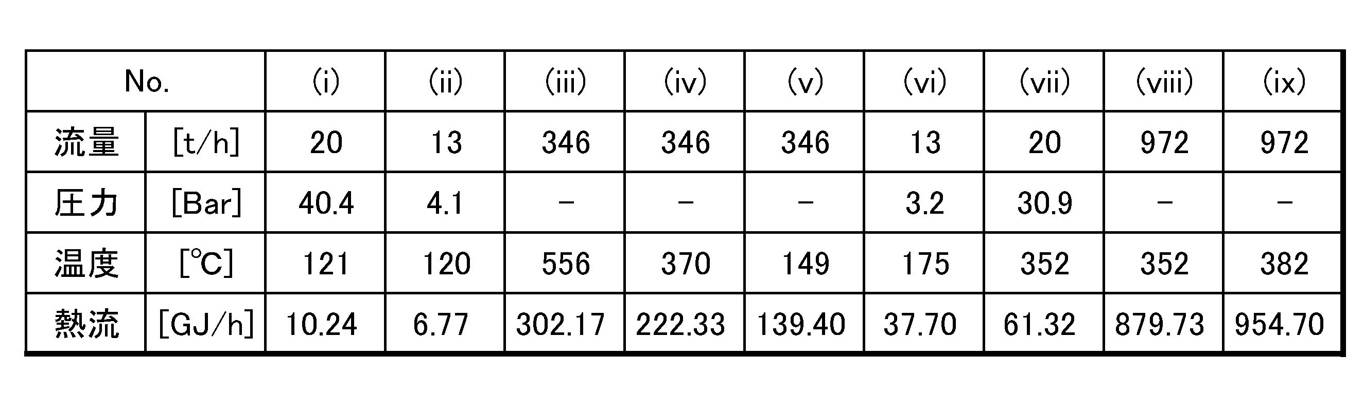
- the exhaust heat recovery unit 3 uses a hot oil heater (heat exchanger) 21 that heats hot oil by using high-temperature exhaust gas introduced from the gas turbine 13, and relatively A high-pressure steam generation unit 22 that generates high-pressure steam at high pressure (here, about 30.9 barA) and a low-pressure steam generation unit 23 that generates low-pressure steam at a relatively low pressure (here, about 3.2 barA) are provided.
- Table 1 shows a material balance and a heat balance in the exhaust heat recovery unit 3.
- the column (i)-(ix) in Table 1 shows the numerical values at each position of the exhaust heat recovery unit 3 with the same numbers (i)-(ix) in FIG.
- the hot oil heater 21 is disposed in the uppermost stream in the exhaust heat recovery unit 3 (that is, the portion through which the hottest exhaust gas flows), and circulates between the hydrogen generation unit 5 and the exhaust heat recovery unit 3 described in detail later. By performing heat exchange between the oil and the exhaust gas, the hot oil is heated so that the temperature of the hot oil falls within a predetermined temperature range.
- the hot oil heater 21 may employ a heat exchanger having a known configuration such as a fin tube heat exchanger.
- the amount of exhaust gas introduced into the hot oil heater 21 is about 346 t / hr.
- the high temperature (here, about 556 ° C.) exhaust gas introduced into the hot oil heater 21 is directed to the high pressure steam generation unit 22 as a lower temperature (here, about 370 ° C.) exhaust gas after heat exchange with the hot oil. Flowing.
- the amount of hot oil introduced into the hot oil heater 21 is about 972 t / hr.
- the hot oil introduced into the hot oil heater 21 at a lower temperature (here, about 352 ° C.) is subjected to heat exchange with the exhaust gas, and then the hydrogen generation unit 5 (hot) as hot oil at a higher temperature (here, about 382 ° C.). It is sent out toward the oil header 52).
- the hot oil is composed of a mixture of diphenyl oxide and biphenyl, and has good chemical stability under the temperature conditions used as a heat source for the dehydrogenation reaction described in detail later. As long as it is (that is, at least not substantially vaporized), a heat medium (such as a synthetic heat medium) composed of other well-known components can be used.
- a heat medium such as a synthetic heat medium
- the high-pressure steam generation unit 22 is disposed downstream of the hot oil heater 21 in the exhaust heat recovery unit 3 and generates high-pressure steam using the heat of the exhaust gas that has passed through the hot oil heater 21.
- the high pressure steam generation unit 22 includes an economizer (preheater) 31 that preheats high pressure feed water for steam generation, an evaporator (evaporator) 32 that vaporizes the preheated high pressure feed water, and a super heater that superheats the vaporized high pressure feed water. (Superheater) 33 is provided in order from the downstream side in the exhaust gas flow.
- the exhaust gas of about 370 ° C. introduced into the high pressure steam generation unit 22 flows toward the low pressure steam generation unit 23 as a lower temperature exhaust gas after heating the high pressure feed water.
- the amount of high-pressure water supplied to the high-pressure steam generation unit 22 is about 20 t / hr.
- the high-pressure feed water having a relatively low temperature here, about 121 ° C.
- the high-pressure steam sent to the gas turbine power generation unit 2 is injected into the combustion chamber for cooling the flame peak temperature of the combustor 12. Thereby, the combustion temperature in the combustor 12 can be lowered, and the generation of nitrogen oxides (NOx) can be reduced.
- NOx nitrogen oxides
- the low-pressure steam generation unit 23 is disposed on the downstream side (that is, the most downstream side) of the high-pressure steam generation unit 22 in the exhaust heat recovery unit 3 and generates low-pressure steam by the heat of the exhaust gas that has passed through the high-pressure steam generation unit 22.
- the low-pressure steam generation unit 23 is provided with an evaporator 35 that vaporizes the low-pressure feed water and a super heater 36 that superheats the vaporized low-pressure feed water from the downstream side in the exhaust gas flow.
- the exhaust gas introduced into the low-pressure steam generating unit 23 is heated to the low-pressure feed water and then sent to the outside as a lower-temperature exhaust gas, and finally enters the atmosphere from the chimney 37 (see FIG. 1). Released.
- the amount of low-pressure water supplied to the low-pressure steam generating unit 23 is about 13 t / hr.
- the relatively low-temperature (here, about 120 ° C.) low-pressure feed water is heated by the exhaust gas, and then sent to the steam power generation unit 4 as higher-temperature (here, about 175 ° C.) low-pressure steam.
- heat exchange between the exhaust gas and the heat medium is performed in the hot oil heater 21 (heat exchange process), and the heat of the exhaust gas after the heat exchange is the high pressure in the high-pressure steam generation unit 22.
- heat exchange process By being used for generation of steam (high-pressure steam generation process) and generation of low-pressure steam in the low-pressure steam generation unit 23 (low-pressure steam generation process), heat recovery of exhaust gas discharged from the gas turbine power generation unit 2 is performed. (Heat exchange process).
- the configuration of the exhaust heat recovery unit 3 is not limited to that shown here, and various changes can be made.
- the super heater 33 in the high-pressure steam generation unit 22 can be disposed on the upstream side of the hot oil heater 21.
- the super heater 36 of the low-pressure steam generating unit 23 can be arranged upstream of the hot oil heater 21.
- the steam power generation unit 4 includes a steam turbine 41 driven by steam, a generator 42 connected to the steam turbine 41, a condenser 43 that cools and condenses exhaust steam discharged from the steam turbine 41, and Is provided.
- an impeller (not shown) of the steam turbine 41 is rotated by high-pressure steam and low-pressure steam introduced from the exhaust heat recovery unit 3 to the high-pressure stage and the low-pressure stage of the steam turbine 41, respectively.
- the energy of the steam is converted into the rotational energy of the impeller, and the rotational energy of the impeller of the steam turbine 41 is further converted into electric power by the generator 42 (second power generation step).
- the steam discharged from the steam turbine 41 is condensed in the condenser 43, and the water generated therein is circulated to the exhaust heat recovery unit 3 and used as low-pressure feed water and high-pressure feed water.
- the steam generated in the exhaust heat recovery unit 3 is used in the steam power generation unit 4 (steam turbine 41).
- steam is used for other well-known purposes. May be.
- the hydrogen generation unit 5 is provided with a dehydrogenation reaction device 51 that generates hydrogen by dehydrogenation of organic hydride based on the organic chemical hydride method.
- the hydrogen generation unit 5 includes heat medium introduction lines L1a and L1b for introducing hot oil heated by the hot oil heater 21 into the dehydrogenation reaction device 51 as a heat source for the dehydrogenation reaction, and a dehydrogenation reaction device 51.
- Heat medium discharge lines L2a and L2b for returning hot oil discharged from the hot oil heater 21 to the hot oil heater 21 are provided.
- An introduction-side hot oil header 52 is provided between the heat medium introduction lines L1a and L1b, and a discharge-side hot oil header 53 is provided between the heat medium discharge lines L2a and L2b.
- the connecting line L3 connecting the discharge side hot oil header 53 and the introduction side hot oil header 52 is provided with a heating furnace (heating device) 54 for reheating the hot oil from the heat medium discharge line L2b.
- a heating furnace heating device
- Each line L1a, L1b, L2a, L2b, L3 provided in the hydrogen generation unit 5 is provided with a pipeline, a valve, a pump, and the like (details not shown) for transporting hot oil.
- a circulation line that circulates between the hot oil heater 21 and the dehydrogenation reactor 51 is configured.
- the dehydrogenation reactor 51 generates hydrogen and an aromatic compound (here, toluene) from an organic hydride (here, methylcyclohexane (hereinafter referred to as “MCH”)) by a dehydrogenation reaction in the presence of a dehydrogenation catalyst. (Dehydrogenation reaction step).
- the dehydrogenation reactor 51 is a heat exchange type fixed-bed multitubular reactor, and has a known configuration in which a plurality of reaction tubes filled with a dehydrogenation catalyst (solid catalyst) are accommodated in a shell. is doing.
- MCH supplied to each reaction tube of the dehydrogenation reaction device 51 from an unshown MCH storage facility (storage tank or the like) flows while contacting the catalyst. Hot oil is supplied to the shell from the heat medium introduction lines L1a and L1b, whereby heat exchange is performed with the reaction tube, and the MCH and the dehydrogenation catalyst are heated.
- hydrogen and toluene are produced from MCH (C7H14) by a dehydrogenation reaction based on the following chemical reaction formula (1).
- the reaction from MCH to toluene and hydrogen is preferably performed under conditions of high temperature and low pressure in terms of chemical equilibrium.
- the reaction temperature is usually the highest at the inlet side temperature of the reaction vessel (temperature of the reactant supply port) and then proceeds to the outlet side of the reaction vessel (that is, the endothermic reaction advances). Therefore, the outlet temperature of the reaction container (the temperature of the product outlet) is lower than the inlet temperature.
- the temperature of the dehydrogenation reaction is controlled within a range of about 350 ° C. to 380 ° C. Thereby, the favorable conversion rate and selectivity in a dehydrogenation reaction can be maintained.
- the reaction pressure for the dehydrogenation reaction is in the range of 0.1 MPaG to 1.0 MPaG.
- the liquid space velocity (LHSV) of MCH is in the range of 0.5h-1 to 5h-1, although it depends on the activity of the catalyst.
- the temperature of the dehydrogenation reaction in the dehydrogenation reactor 51 is controlled by the temperature and flow rate of the hot oil introduced.
- the heat medium discharge line L2a is provided with a temperature detector 61 for detecting the temperature of the hot oil discharged from the dehydrogenation reaction device 51, and the heat medium introduction line L1b has a temperature detector 61.
- a flow rate adjustment valve 62 for adjusting the flow rate of hot oil introduced into the dehydrogenation reactor 51 is provided.
- the heating of the hot oil in the exhaust heat recovery unit 3 is controlled so that the introduction temperature of the hot oil introduced into the dehydrogenation reactor 51 from the heat medium introduction line L1b is within the range of 352 ° C to 392 ° C. Is done. More preferably, the temperature of the hot oil is controlled to be in the range of 365 ° C to 385 ° C. When the temperature is 352 ° C. or lower, the reaction does not proceed in a balanced manner, which is disadvantageous for heat exchange efficiency. On the other hand, when the temperature is 392 ° C. or higher, the heat medium is easily pyrolyzed and does not perform a desired function.
- the heat transfer coefficient and the heat capacity are higher than those of the exhaust gas, and the exhaust gas from the gas turbine power generation unit 2 is directly introduced into the dehydrogenation reactor 51.
- the heat transfer efficiency to the reaction vessel can be improved.
- the heat transfer area for the reaction vessel of the dehydrogenation reactor 51 can be reduced and the amount of dehydrogenation catalyst used can be reduced compared to the case of exhaust gas.
- the heat transfer coefficient on the outer surface of the heat transfer tube can be improved by about 5 times, and the heat transfer area can be reduced by nearly 50%.
- the introduction temperature to the dehydrogenation reactor 51 can be lowered compared to the case of exhaust gas (need to be about 500 ° C. or higher), and a high-temperature heat medium It is possible to suppress adverse effects on the reactor or the like due to the introduction of (such as a decrease in the activity of the catalyst).
- the flow rate of the hot oil by the flow rate adjusting valve 62 is such that the discharge temperature of the hot oil discharged from the dehydrogenation reaction device 51 (here, the detection value of the temperature detector 61) is in the range of 337 ° C. to 367 ° C. It is controlled to become. More preferably, the hot oil temperature is controlled to be within a range of 347 ° C to 357 ° C.
- the temperature difference between the hot oil introduced into the dehydrogenation reactor 51 and the hot oil discharged from the dehydrogenation reactor 51 is in the range of 10 ° C. to 50 ° C., preferably 20 ° C. to 40 ° C. Need to be controlled. More preferably, the temperature difference is controlled to be within a range of 25 ° C. to 35 ° C. If the temperature difference is 10 ° C or less, a very large amount of hot oil flow is required. On the other hand, when the temperature difference is 50 ° C. or more, heat input does not proceed, resulting in an increase in the reactor volume. Incidentally, in the case of the present invention, the temperature difference can be reduced to about half compared with the prior art.
- the heating furnace 54 heats hot oil circulating in the heating coil by the combustion heat of a predetermined fuel.
- the temperature of the hot oil introduced into the dehydrogenation reactor 51 can be easily adjusted to an appropriate range, and the temperature of the hot oil can be increased or decreased within the range.
- the means for heating the hot oil is not limited to the heating furnace 54 shown here, and any other known heating device can be employed as long as at least the hot oil can be heated to a desired temperature.
- the hydrogen produced in the dehydrogenation reactor 51 is sent to a hydrogen demand destination such as a city via the first hydrogen supply line L5. Further, a part of the hydrogen is sent to the gas turbine power generation unit 2 side via the second hydrogen supply line L6 branched from the first hydrogen supply line L5 and mixed with natural gas, or separately in the combustor. Used as 12 fuels. In this way, by using the hydrogen generated in the dehydrogenation reactor 51 as a fuel for power generation (hydrogen cogeneration), it is possible to effectively use the hydrogen and receive it from other hydrogen customers. The balance can be further stabilized.
- the toluene produced in the dehydrogenation reactor 51 is separated from hydrogen and then stored in a toluene storage facility (storage tank or the like).
- the stored toluene is supplied to a hydrogenation device (not shown) and can be used as a reaction product of a hydrogenation reaction for generating MCH.
- the organic hydride used in the dehydrogenation reaction is not limited to MCH, but a monocyclic organic hydride such as cyclohexane, a bicyclic organic hydride such as tetralin, decalin, or methyldecalin, or tetradecahydroanthracene. Etc., such as a tricyclic organic hydride, etc., or a mixture of two or more thereof.
- the temperature of the hot oil introduced into the dehydrogenation reactor 51 can be appropriately changed within the above temperature range depending on the type of organic hydride.
- the aromatic compound produced by dehydrogenation of the organic hydride is not particularly limited to toluene, and examples thereof include monocyclic aromatic compounds such as benzene and xylene, and bicyclic rings such as naphthalene, tetralin, and methylnaphthalene. It may be a single aromatic compound, a tricyclic aromatic compound such as anthracene, or a mixture of two or more.
- the dehydrogenation catalyst is made of nickel (Ni), platinum (Pt), palladium (Pd), rhodium (Rh), iridium (Ir), and ruthenium (Ru) on a support selected from alumina, silica alumina, and silica.
- the catalyst is supported on at least one selected active metal, but is not limited to this, and a known catalyst used for organic hydride dehydrogenation can be used.
- a uniform highly dispersed metal catalyst is effective as the dehydrogenation catalyst.
- the catalyst metal is supported substantially in accordance with the distribution of sulfur or sulfur compounds by pre-dispersing sulfur or sulfur compounds substantially uniformly over the entire cross section of the catalyst support.
- the catalytic metal is supported in a substantially uniformly dispersed state over the entire support cross section.
- the catalyst support is alumina
- the slurry of aluminum hydroxide produced by neutralization of the aluminum salt is filtered and washed, and the obtained alumina hydrogel is dehydrated and washed, and then at 400 to 800 ° C. for 1 to 6 hours.
- a porous ⁇ -alumina support obtained by baking to a certain extent is preferred, and furthermore, the pH value of the alumina hydrogel is alternately varied between the alumina hydrogel dissolution pH region and the boehmite gel precipitation pH region, and at least one of them. More preferred is a porous ⁇ -alumina support obtained through a pH swing process in which an alumina hydrogel-forming substance is added to grow crystals of alumina hydrogel upon pH change from one pH region to the other.
- Such a porous ⁇ -alumina carrier is excellent in that the physical properties of each pellet are stable and there is little variation in physical properties even in the molded alumina pellets with excellent uniformity of pore distribution. ing.
- the catalyst is excellent in catalytic activity and selectivity, and in addition, the catalyst can exhibit more excellent functions in a long life.
- the combination of the gas turbine power generation unit 2 that can use hydrogen as a fuel and the hydrogen generation unit 5 effectively eliminates exhaust heat generated by power generation in the hydrogen generation unit 5 based on the organic chemical hydride method. Can be used.
- hot oil liquid state having higher heat transfer efficiency than the exhaust gas is used as the heat source for the dehydrogenation reaction, and when introduced into the dehydrogenation reactor 51
- the temperature of the hot oil at the time of discharge from the dehydrogenation reactor 51 and the temperature difference of the hot oil at the time of introduction and discharge are set to an appropriate range, so that the temperature of the dehydrogenation reaction is controlled to an appropriate range.
- Hydrogen production system Gas turbine power generation unit (first power generation unit) 3 Waste heat recovery unit 4 Steam power generation unit (second power generation unit) 5 Hydrogen generation unit 12 Combustor 21 Hot oil heater (heat exchanger) 22 High pressure steam generation unit 23 Low pressure steam generation unit 31 Economizer (preheater) 32 Evaporator 33 Super heater (superheater) 35 Evaporator 36 Superheater 51 Dehydrogenation reactor 52 Introduction side hot oil header 53 Discharge side hot oil header 54 Heating furnace (heating device) 61 Temperature detector 62 Flow rate adjusting valves L1a, L1b Heat medium introduction line (circulation line) L2a, L2b Heat medium discharge line (circulation line) L3 connection line (circulation line) L5 1st hydrogen supply line L6 2nd hydrogen supply line
Landscapes
- Engineering & Computer Science (AREA)
- Chemical & Material Sciences (AREA)
- Combustion & Propulsion (AREA)
- General Engineering & Computer Science (AREA)
- Mechanical Engineering (AREA)
- Organic Chemistry (AREA)
- Chemical Kinetics & Catalysis (AREA)
- General Health & Medical Sciences (AREA)
- Inorganic Chemistry (AREA)
- Health & Medical Sciences (AREA)
- Oil, Petroleum & Natural Gas (AREA)
- General Chemical & Material Sciences (AREA)
- Hydrogen, Water And Hydrids (AREA)
- Engine Equipment That Uses Special Cycles (AREA)
Abstract
Description

2 ガスタービン発電ユニット(第1発電ユニット)
3 排熱回収ユニット
4 蒸気発電ユニット(第2発電ユニット)
5 水素生成ユニット
12 燃焼器
21 ホットオイルヒータ(熱交換器)
22 高圧蒸気発生ユニット
23 低圧蒸気発生ユニット
31 エコノマイザ(予熱器)
32 エバポレータ(蒸発器)
33 スーパーヒータ(過熱器)
35 エバポレータ
36 スーパーヒータ
51 脱水素反応装置
52 導入側ホットオイルヘッダ
53 排出側ホットオイルヘッダ
54 加熱炉(加熱装置)
61 温度検出器
62 流量調整弁
L1a、L1b 熱媒体導入ライン(循環ライン)
L2a、L2b 熱媒体排出ライン(循環ライン)
L3 接続ライン(循環ライン)
L5 第1水素供給ライン
L6 第2水素供給ライン
Claims (8)
- 脱水素触媒の存在下での脱水素反応によって有機ハイドライドから水素を生成する脱水素反応装置と、
燃料の燃焼によって発生する燃焼ガスのエネルギーに基づき発電を行う第1発電ユニットと、
前記第1発電ユニットから排出される排ガスの熱回収を行う排熱回収ユニットと、
前記排熱回収ユニットに設けられ、前記排ガスと熱媒体との熱交換を行う熱交換器と、
前記熱交換器で加熱された前記熱媒体を液体状態で前記脱水素反応装置に導入すると共に、前記脱水素反応装置から排出された前記熱媒体を前記熱交換器に戻す循環ラインと
を備え、
前記脱水素反応装置に導入される前記熱媒体の導入温度は、352℃~392℃の範囲内にあり、
前記脱水素反応装置から排出される前記熱媒体の排出温度は、337℃~367℃の範囲内にあり、
前記導入温度と前記排出温度との温度差が10℃~50℃の範囲内にあることを特徴とする水素製造システム。 - 前記排熱回収ユニットは、前記排ガスの熱を利用して蒸気を発生させる少なくとも1つの蒸気発生ユニットを更に備えたことを特徴とする請求項1に記載の水素製造システム。
- 前記蒸気発生ユニットには、より圧力の高い高圧蒸気を発生させる高圧蒸気発生ユニットと、より圧力の低い低圧蒸気を発生させる低圧蒸気発生ユニットとが含まれ、
前記高圧蒸気および前記低圧蒸気のエネルギーに基づき発電を行う第2発電ユニットを更に備えたことを特徴とする請求項1または請求項2に記載の水素製造システム。 - 前記第1発電ユニットは、前記燃料を燃焼させる燃焼器を有し、
前記蒸気が前記燃焼器に導入されることを特徴とする請求項2または請求項3に記載の水素製造システム。 - 前記循環ラインを流れる前記熱媒体の少なくとも一部を加熱する加熱装置を更に備えたことを特徴とする請求項1から請求項4のいずれかに記載の水素製造システム。
- 前記燃料には、前記脱水素反応装置において生成された水素が含まれることを特徴とする請求項1から請求項5のいずれかに記載の水素製造システム。
- 前記蒸気発生ユニットは、水を気化させる蒸発器および気化した水を過熱する過熱器を含み、
前記蒸発器が、前記熱交換器の下流側に配置される一方、前記過熱器が、前記熱交換器の上流側に配置されることを特徴とする請求項2または請求項3のいずれかに記載の水素製造システム。 - 脱水素触媒の存在下での脱水素反応によって有機ハイドライドから水素を生成する脱水素反応工程と、
燃料の燃焼によって発生する燃焼ガスのエネルギーに基づき発電を行う第1発電工程と、
前記第1発電工程において排出される排ガスの熱回収を行う排熱回収工程と、
前記排熱回収工程において、前記排ガスと熱媒体との熱交換を行う熱交換工程と
を有し、
前記脱水素反応工程では、前記熱交換工程で加熱された前記熱媒体が液体状態で前記脱水素反応の熱源として使用されると共に、当該使用された後の前記熱媒体が前記熱交換工程で再加熱され、
前記脱水素反応工程における前記熱媒体の使用前の温度は、352℃~392℃の範囲内にあり、
前記脱水素反応工程における前記熱媒体の使用後の温度は、337℃~367℃の範囲内にあり、
前記使用前と前記使用後とにおける前記熱媒体の温度差が10℃~50℃の範囲内にあることを特徴とする水素製造方法。
Priority Applications (4)
| Application Number | Priority Date | Filing Date | Title |
|---|---|---|---|
| CA2941705A CA2941705C (en) | 2014-03-26 | 2015-03-25 | System and method for producing hydrogen |
| KR1020167029859A KR102313014B1 (ko) | 2014-03-26 | 2015-03-25 | 수소 제조 시스템 및 수소 제조 방법 |
| EP15767992.9A EP3124432B1 (en) | 2014-03-26 | 2015-03-25 | Hydrogen generation system and hydrogen generation method |
| US15/125,272 US10167777B2 (en) | 2014-03-26 | 2015-03-25 | System and method for producing hydrogen |
Applications Claiming Priority (2)
| Application Number | Priority Date | Filing Date | Title |
|---|---|---|---|
| JP2014-064627 | 2014-03-26 | ||
| JP2014064627A JP6244242B2 (ja) | 2014-03-26 | 2014-03-26 | 水素製造システム及び水素製造方法 |
Publications (1)
| Publication Number | Publication Date |
|---|---|
| WO2015146170A1 true WO2015146170A1 (ja) | 2015-10-01 |
Family
ID=54194714
Family Applications (1)
| Application Number | Title | Priority Date | Filing Date |
|---|---|---|---|
| PCT/JP2015/001706 WO2015146170A1 (ja) | 2014-03-26 | 2015-03-25 | 水素製造システム及び水素製造方法 |
Country Status (8)
| Country | Link |
|---|---|
| US (1) | US10167777B2 (ja) |
| EP (1) | EP3124432B1 (ja) |
| JP (1) | JP6244242B2 (ja) |
| KR (1) | KR102313014B1 (ja) |
| AR (1) | AR099852A1 (ja) |
| CA (1) | CA2941705C (ja) |
| TW (1) | TWI633050B (ja) |
| WO (1) | WO2015146170A1 (ja) |
Cited By (6)
| Publication number | Priority date | Publication date | Assignee | Title |
|---|---|---|---|---|
| JP2018118892A (ja) * | 2017-01-27 | 2018-08-02 | 関西電力株式会社 | 水素製造設備、発電システム及び水素製造方法 |
| WO2019211300A1 (en) | 2018-05-02 | 2019-11-07 | Hysilabs, Sas | Hydrogen carrier compounds |
| EP3816204A1 (en) | 2019-10-31 | 2021-05-05 | Hysilabs, SAS | Process for producing and regenerating hydrogen carrier compounds |
| WO2021084046A1 (en) | 2019-10-31 | 2021-05-06 | Hysilabs Sas | Process for producing and regenerating hydrogen carrier compounds |
| WO2021084044A1 (en) | 2019-10-31 | 2021-05-06 | Hysilabs Sas | Hydrogen carrier compounds |
| EP4108630A1 (en) | 2021-06-25 | 2022-12-28 | Hysilabs, SAS | Hydrogen carrier compounds |
Families Citing this family (10)
| Publication number | Priority date | Publication date | Assignee | Title |
|---|---|---|---|---|
| US10458329B2 (en) * | 2014-03-06 | 2019-10-29 | Uop Llc | System and process for recovering power and steam from regenerator flue gas |
| WO2016048383A1 (en) | 2014-09-27 | 2016-03-31 | Intel Corporation | Substrate warpage control using temper glass with uni-directional heating |
| JP6417167B2 (ja) * | 2014-09-29 | 2018-10-31 | 川崎重工業株式会社 | ガスタービン |
| JP6609180B2 (ja) | 2015-12-24 | 2019-11-20 | 株式会社東芝 | プラント制御装置、プラント制御方法、および発電プラント |
| DE202017003690U1 (de) * | 2017-07-13 | 2018-10-16 | Thomas Lamla | Wasserstoff-Dampf-Kraft-Werk |
| JP7143120B2 (ja) | 2018-06-01 | 2022-09-28 | 株式会社神戸製鋼所 | ガス供給システム |
| CN109306918B (zh) * | 2018-09-26 | 2021-09-21 | 云南电网有限责任公司电力科学研究院 | 一种直接利用液体有机储氢材料的热气机 |
| CN109850846B (zh) * | 2019-01-29 | 2022-06-07 | 武汉船用电力推进装置研究所(中国船舶重工集团公司第七一二研究所) | 一种自热式有机液体脱氢供氢系统及其应用 |
| US20220333783A1 (en) * | 2021-03-07 | 2022-10-20 | CPS-Holding Limited | Hydrogen-Fueled Combustor for Gas Turbines |
| WO2022216779A1 (en) * | 2021-04-08 | 2022-10-13 | Siemens Energy Global GmbH & Co. KG | On-demand hydrogen for power generation |
Citations (2)
| Publication number | Priority date | Publication date | Assignee | Title |
|---|---|---|---|---|
| JP2012206909A (ja) * | 2011-03-30 | 2012-10-25 | Chiyoda Kako Kensetsu Kk | ハイブリッド型水素製造・発電システム |
| JP2013067588A (ja) * | 2011-09-22 | 2013-04-18 | Hitachi Ltd | 動力変換システム |
Family Cites Families (9)
| Publication number | Priority date | Publication date | Assignee | Title |
|---|---|---|---|---|
| JPS61236706A (ja) * | 1985-04-14 | 1986-10-22 | Somar Corp | 防菌剤 |
| JP4279546B2 (ja) | 2002-12-20 | 2009-06-17 | 千代田化工建設株式会社 | 高圧水素の供給システム |
| US7351395B1 (en) * | 2003-05-06 | 2008-04-01 | Air Products And Chemicals, Inc. | Hydrogen storage by reversible hydrogenation of pi-conjugated substrates |
| CA2606117A1 (en) * | 2005-05-02 | 2006-11-16 | Hrein Energy, Inc. | Organic hydride synthesizing apparatus, organic hydride synthesizing system and hydrogen production apparatus |
| JP5046359B2 (ja) | 2006-03-06 | 2012-10-10 | 株式会社フレイン・エナジー | 水素発生装置および水素添加反応装置 |
| JP4483901B2 (ja) * | 2007-06-29 | 2010-06-16 | 株式会社日立製作所 | エンジンシステム |
| US20110274994A1 (en) * | 2010-05-07 | 2011-11-10 | Carrier Andrew J | Catalyst and Liquid Combination for a Thermally Regenerative Fuel Cell |
| WO2012014225A2 (en) * | 2010-07-26 | 2012-02-02 | Council Of Scientific & Industrial Research | An improved process for the storage delivery of hydrogen using catalyst |
| JP5856484B2 (ja) * | 2012-01-06 | 2016-02-09 | 株式会社日立製作所 | 動力変換システム |
-
2014
- 2014-03-26 JP JP2014064627A patent/JP6244242B2/ja active Active
-
2015
- 2015-03-25 US US15/125,272 patent/US10167777B2/en active Active
- 2015-03-25 CA CA2941705A patent/CA2941705C/en active Active
- 2015-03-25 EP EP15767992.9A patent/EP3124432B1/en active Active
- 2015-03-25 KR KR1020167029859A patent/KR102313014B1/ko active IP Right Grant
- 2015-03-25 WO PCT/JP2015/001706 patent/WO2015146170A1/ja active Application Filing
- 2015-03-26 AR ARP150100896A patent/AR099852A1/es active IP Right Grant
- 2015-03-26 TW TW104109786A patent/TWI633050B/zh active
Patent Citations (2)
| Publication number | Priority date | Publication date | Assignee | Title |
|---|---|---|---|---|
| JP2012206909A (ja) * | 2011-03-30 | 2012-10-25 | Chiyoda Kako Kensetsu Kk | ハイブリッド型水素製造・発電システム |
| JP2013067588A (ja) * | 2011-09-22 | 2013-04-18 | Hitachi Ltd | 動力変換システム |
Non-Patent Citations (1)
| Title |
|---|
| See also references of EP3124432A4 * |
Cited By (8)
| Publication number | Priority date | Publication date | Assignee | Title |
|---|---|---|---|---|
| JP2018118892A (ja) * | 2017-01-27 | 2018-08-02 | 関西電力株式会社 | 水素製造設備、発電システム及び水素製造方法 |
| WO2019211300A1 (en) | 2018-05-02 | 2019-11-07 | Hysilabs, Sas | Hydrogen carrier compounds |
| WO2019211301A1 (en) | 2018-05-02 | 2019-11-07 | Hysilabs, Sas | Process for producing and regenerating hydrogen carrier compounds |
| EP3816204A1 (en) | 2019-10-31 | 2021-05-05 | Hysilabs, SAS | Process for producing and regenerating hydrogen carrier compounds |
| WO2021084046A1 (en) | 2019-10-31 | 2021-05-06 | Hysilabs Sas | Process for producing and regenerating hydrogen carrier compounds |
| WO2021084044A1 (en) | 2019-10-31 | 2021-05-06 | Hysilabs Sas | Hydrogen carrier compounds |
| EP4108630A1 (en) | 2021-06-25 | 2022-12-28 | Hysilabs, SAS | Hydrogen carrier compounds |
| WO2022269009A1 (en) | 2021-06-25 | 2022-12-29 | Hysilabs Sas | Hydrogen carrier compounds |
Also Published As
| Publication number | Publication date |
|---|---|
| TW201542448A (zh) | 2015-11-16 |
| CA2941705C (en) | 2022-04-12 |
| KR102313014B1 (ko) | 2021-10-14 |
| US10167777B2 (en) | 2019-01-01 |
| EP3124432B1 (en) | 2019-01-09 |
| JP2015187049A (ja) | 2015-10-29 |
| JP6244242B2 (ja) | 2017-12-06 |
| KR20160140789A (ko) | 2016-12-07 |
| EP3124432A1 (en) | 2017-02-01 |
| AR099852A1 (es) | 2016-08-24 |
| EP3124432A4 (en) | 2017-12-27 |
| CA2941705A1 (en) | 2015-10-01 |
| TWI633050B (zh) | 2018-08-21 |
| US20170074163A1 (en) | 2017-03-16 |
Similar Documents
| Publication | Publication Date | Title |
|---|---|---|
| JP6244242B2 (ja) | 水素製造システム及び水素製造方法 | |
| EP3054519A1 (en) | Reversible fuel cell system and method for operating a fuel cell system | |
| US11674068B2 (en) | Hydrogen extraction reactor and hydrogen extraction process using phase change materials | |
| JP2007238341A (ja) | 水素発生装置および水素添加反応装置 | |
| JP6194143B2 (ja) | 水素及び合成天然ガスの製造装置及び製造方法 | |
| JP5897811B2 (ja) | ハイブリッド型水素製造・発電システム | |
| CN110606467B (zh) | 一种甲醇重整制氢工艺及系统 | |
| WO2015033583A1 (ja) | 水素及び合成天然ガスの製造装置及び製造方法 | |
| JP6437191B2 (ja) | 水素製造システム及びこれを備えた水素貯蔵・輸送システム並びに水素製造方法 | |
| CN113292045A (zh) | 一种甲醇水重整制氢系统及控制方法 | |
| JP5602698B2 (ja) | 動力変換システム | |
| JP6964920B1 (ja) | 発電設備併設気化利用炭化水素製造システム | |
| WO2012140994A1 (ja) | Co2を排出しない合成ガスの製造方法 | |
| JP2015182919A (ja) | 水素製造システム及び水素製造方法 | |
| WO2014065020A1 (ja) | サチュレータ及びこれを備える天然ガス改質システム | |
| JP5132183B2 (ja) | 水素製造装置 | |
| JP7033094B2 (ja) | コージェネレーションシステム | |
| WO2017121978A1 (en) | Methanol process | |
| WO2015129228A1 (ja) | 芳香族化合物の水素化システムおよび水素化方法 | |
| WO2015114716A1 (ja) | 熱輸送システム | |
| JP2007186572A (ja) | 重質油の改質装置、重質油改質装置を備えたガスタービン、重質油改質装置を備えたガスタービンプラント、及び重質油の改質方法 | |
| JP2017133701A (ja) | 燃焼ガス供給システム | |
| JP2773334B2 (ja) | メタノール改質反応装置 | |
| JP2803266B2 (ja) | メタノール改質反応装置 | |
| CN115614717A (zh) | 一种二氧化碳热催化还原的余热利用技术与系统装置 |
Legal Events
| Date | Code | Title | Description |
|---|---|---|---|
| 121 | Ep: the epo has been informed by wipo that ep was designated in this application |
Ref document number: 15767992 Country of ref document: EP Kind code of ref document: A1 |
|
| ENP | Entry into the national phase |
Ref document number: 2941705 Country of ref document: CA |
|
| WWE | Wipo information: entry into national phase |
Ref document number: 15125272 Country of ref document: US |
|
| REEP | Request for entry into the european phase |
Ref document number: 2015767992 Country of ref document: EP |
|
| WWE | Wipo information: entry into national phase |
Ref document number: 2015767992 Country of ref document: EP |
|
| NENP | Non-entry into the national phase |
Ref country code: DE |
|
| ENP | Entry into the national phase |
Ref document number: 20167029859 Country of ref document: KR Kind code of ref document: A |