WO2015146152A1 - 統合装置 - Google Patents
統合装置 Download PDFInfo
- Publication number
- WO2015146152A1 WO2015146152A1 PCT/JP2015/001668 JP2015001668W WO2015146152A1 WO 2015146152 A1 WO2015146152 A1 WO 2015146152A1 JP 2015001668 W JP2015001668 W JP 2015001668W WO 2015146152 A1 WO2015146152 A1 WO 2015146152A1
- Authority
- WO
- WIPO (PCT)
- Prior art keywords
- solar radiation
- light
- elevation angle
- windshield
- detection element
- Prior art date
- Legal status (The legal status is an assumption and is not a legal conclusion. Google has not performed a legal analysis and makes no representation as to the accuracy of the status listed.)
- Ceased
Links
Images




Classifications
-
- G—PHYSICS
- G01—MEASURING; TESTING
- G01J—MEASUREMENT OF INTENSITY, VELOCITY, SPECTRAL CONTENT, POLARISATION, PHASE OR PULSE CHARACTERISTICS OF INFRARED, VISIBLE OR ULTRAVIOLET LIGHT; COLORIMETRY; RADIATION PYROMETRY
- G01J1/00—Photometry, e.g. photographic exposure meter
- G01J1/02—Details
- G01J1/04—Optical or mechanical part supplementary adjustable parts
- G01J1/0407—Optical elements not provided otherwise, e.g. manifolds, windows, holograms, gratings
- G01J1/0411—Optical elements not provided otherwise, e.g. manifolds, windows, holograms, gratings using focussing or collimating elements, i.e. lenses or mirrors; Aberration correction
-
- B—PERFORMING OPERATIONS; TRANSPORTING
- B60—VEHICLES IN GENERAL
- B60R—VEHICLES, VEHICLE FITTINGS, OR VEHICLE PARTS, NOT OTHERWISE PROVIDED FOR
- B60R11/00—Arrangements for holding or mounting articles, not otherwise provided for
- B60R11/04—Mounting of cameras operative during drive; Arrangement of controls thereof relative to the vehicle
-
- G—PHYSICS
- G01—MEASURING; TESTING
- G01J—MEASUREMENT OF INTENSITY, VELOCITY, SPECTRAL CONTENT, POLARISATION, PHASE OR PULSE CHARACTERISTICS OF INFRARED, VISIBLE OR ULTRAVIOLET LIGHT; COLORIMETRY; RADIATION PYROMETRY
- G01J1/00—Photometry, e.g. photographic exposure meter
- G01J1/02—Details
-
- G—PHYSICS
- G01—MEASURING; TESTING
- G01J—MEASUREMENT OF INTENSITY, VELOCITY, SPECTRAL CONTENT, POLARISATION, PHASE OR PULSE CHARACTERISTICS OF INFRARED, VISIBLE OR ULTRAVIOLET LIGHT; COLORIMETRY; RADIATION PYROMETRY
- G01J1/00—Photometry, e.g. photographic exposure meter
- G01J1/02—Details
- G01J1/0266—Field-of-view determination; Aiming or pointing of a photometer; Adjusting alignment; Encoding angular position; Size of the measurement area; Position tracking; Photodetection involving different fields of view for a single detector
-
- G—PHYSICS
- G01—MEASURING; TESTING
- G01J—MEASUREMENT OF INTENSITY, VELOCITY, SPECTRAL CONTENT, POLARISATION, PHASE OR PULSE CHARACTERISTICS OF INFRARED, VISIBLE OR ULTRAVIOLET LIGHT; COLORIMETRY; RADIATION PYROMETRY
- G01J1/00—Photometry, e.g. photographic exposure meter
- G01J1/02—Details
- G01J1/0271—Housings; Attachments or accessories for photometers
-
- G—PHYSICS
- G01—MEASURING; TESTING
- G01J—MEASUREMENT OF INTENSITY, VELOCITY, SPECTRAL CONTENT, POLARISATION, PHASE OR PULSE CHARACTERISTICS OF INFRARED, VISIBLE OR ULTRAVIOLET LIGHT; COLORIMETRY; RADIATION PYROMETRY
- G01J1/00—Photometry, e.g. photographic exposure meter
- G01J1/02—Details
- G01J1/04—Optical or mechanical part supplementary adjustable parts
- G01J1/0407—Optical elements not provided otherwise, e.g. manifolds, windows, holograms, gratings
-
- B—PERFORMING OPERATIONS; TRANSPORTING
- B60—VEHICLES IN GENERAL
- B60R—VEHICLES, VEHICLE FITTINGS, OR VEHICLE PARTS, NOT OTHERWISE PROVIDED FOR
- B60R11/00—Arrangements for holding or mounting articles, not otherwise provided for
- B60R2011/0001—Arrangements for holding or mounting articles, not otherwise provided for characterised by position
- B60R2011/0003—Arrangements for holding or mounting articles, not otherwise provided for characterised by position inside the vehicle
- B60R2011/0026—Windows, e.g. windscreen
-
- G—PHYSICS
- G01—MEASURING; TESTING
- G01J—MEASUREMENT OF INTENSITY, VELOCITY, SPECTRAL CONTENT, POLARISATION, PHASE OR PULSE CHARACTERISTICS OF INFRARED, VISIBLE OR ULTRAVIOLET LIGHT; COLORIMETRY; RADIATION PYROMETRY
- G01J1/00—Photometry, e.g. photographic exposure meter
- G01J1/02—Details
- G01J1/04—Optical or mechanical part supplementary adjustable parts
- G01J2001/0485—Cosinus correcting or purposely modifying the angular response of a light sensor
-
- G—PHYSICS
- G01—MEASURING; TESTING
- G01J—MEASUREMENT OF INTENSITY, VELOCITY, SPECTRAL CONTENT, POLARISATION, PHASE OR PULSE CHARACTERISTICS OF INFRARED, VISIBLE OR ULTRAVIOLET LIGHT; COLORIMETRY; RADIATION PYROMETRY
- G01J1/00—Photometry, e.g. photographic exposure meter
- G01J1/42—Photometry, e.g. photographic exposure meter using electric radiation detectors
- G01J2001/4266—Photometry, e.g. photographic exposure meter using electric radiation detectors for measuring solar light
Definitions
- This disclosure relates to an integrated device in which an in-vehicle product and a solar radiation sensor are integrated.
- Patent Document 1 proposes an optical sensor in which a plurality of sensors are integrated. Specifically, a configuration in which a rain sensor and an ambient light sensor are integrated has been proposed.
- the light sensor is attached to the windshield of the vehicle.
- the rain sensor measures a change in refractive characteristics due to raindrops attached to the windshield as a change in light intensity.
- the ambient light sensor detects the brightness of ambient light incident from the outside of the passenger compartment through the windshield.
- the solar radiation sensor that detects the amount of solar radiation entering the vehicle interior of the vehicle is configured to detect the amount of solar radiation according to a predetermined elevation angle characteristic.
- the solar radiation sensor is mounted on the dashboard of the vehicle.
- the solar radiation sensor with the rain sensor into one package.
- the elevation angle characteristics of the solar radiation sensor may be affected by the inclination angle of the windshield.
- the solar radiation sensor can capture light from above the vehicle, but it becomes difficult to capture light from the front of the vehicle.
- the solar radiation sensor is attached to the windshield having a large inclination angle, light from the front of the vehicle can be captured, but it becomes difficult to capture light from above the vehicle.
- the in-vehicle product combined with the solar radiation sensor is not limited to the rain sensor. That is, the above-described situation occurs when the solar radiation sensor is integrated with the in-vehicle product attached to the windshield.
- This indication aims at providing the integrated apparatus which can reduce the influence which the elevation angle characteristic of a solar radiation sensor receives by the inclination angle of a windshield when integrating a vehicle-mounted product and a solar radiation sensor in view of the said point. .
- the first aspect of the present disclosure includes an in-vehicle product that is fixed to the windshield of the vehicle.
- the solar radiation detection element that detects the amount of solar radiation by receiving the solar radiation incident on the windshield, and guides the solar radiation incident on the windshield in a predetermined elevation angle range to the solar radiation detection element, with respect to the solar radiation detection element
- a solar radiation lens unit having a solar radiation peak at a predetermined angle in the elevation angle range, and a solar radiation sensor integrated with the vehicle-mounted product.
- the solar radiation lens unit includes a peak adjustment unit that stabilizes the amount of solar radiation within a certain range including a predetermined angle in the elevation angle range.
- the peak range of the solar radiation amount in the elevation angle range is expanded by the peak adjustment unit, the required elevation angle characteristics can be obtained even with respect to the difference in the inclination angle of the vehicle windshield. That is, the solar radiation sensor can be applied to windshields having various inclination angles. Therefore, the influence which the elevation angle characteristic of a solar radiation sensor receives with the inclination-angle of a windshield can be reduced.
- the integrated device is an integration of, for example, a rain sensor that detects raindrops attached to a windshield of a vehicle and a solar sensor that detects the amount of solar radiation around the vehicle.
- the integrated device 1 is installed on the passenger compartment side of the windshield 100.
- the vehicle glass angle ⁇ of the windshield 100 is different for each vehicle type.
- the integrated device 1 includes a cover housing 10, a circuit board 20, a rain sensor 30, and a solar radiation sensor 40.
- the rain sensor 30 includes a light emitting element 31, a light receiving element 32, and a light guiding lens unit 33.
- the solar radiation sensor 40 includes a solar radiation detection element 41 and a solar radiation lens unit 42.
- the cover housing 10 is an appearance of the integrated device 1.
- the cover housing 10 is a housing for housing the circuit board 20, the rain sensor 30, and the solar radiation sensor 40.
- the cover housing 10 is formed from a metal material or a resin material.
- the planar shape of the cover housing 10 when viewed from the open end 11 side to the bottom surface 12 side is, for example, a quadrangular shape.
- the cover housing 10 is attached to a bracket (not shown) fixed to the windshield 100.
- the cover housing 10 comprises a container with a bracket.
- the bracket is, for example, a metal plate pressed into a predetermined shape, and is fixed to the windshield 100 with an adhesive or the like.
- the circuit board 20 has a light emitting element 31 and a light receiving element 32 of the rain sensor 30 mounted thereon, and a solar radiation detecting element 41 of the solar radiation sensor 40 mounted thereon.
- the circuit board 20 is a plate having a surface 21.
- the circuit board 20 is, for example, a printed board.
- the circuit board 20 has a connector 22 and electronic components (not shown) mounted on the one surface 21.
- the connector 22 is a resin connection component to which a wiring connector (not shown) is connected.
- the connector 22 has a terminal 23 that is electrically connected to a circuit formed on the circuit board 20.
- the terminal 23 is insert-molded in the connector 22.
- the electronic component is, for example, an IC, a resistance element, a chip capacitor, or the like.
- the circuit board 20 is accommodated on the bottom surface 12 side of the cover housing 10 with the one surface 21 side facing the open end 11 of the cover housing 10.
- the rain sensor 30 is a raindrop detection device configured to detect raindrops attached to the windshield 100 of the vehicle.
- the integrated device 1 is one in which a solar radiation sensor 40 is integrated with a rain sensor 30. That is, the cover housing 10 and the circuit board 20 that constitute the integrated device 1 are components that constitute the rain sensor 30.
- the light emitting element 31 is a light emitting device that emits measurement light for detecting raindrops attached to the windshield 100.
- the light emitting element 31 includes a light emitting diode (LED) that emits light toward the windshield 100 and a drive circuit (not shown) that drives the light emitting diode.
- the drive circuit performs PWM control of the light emitting diode, for example. That is, the drive circuit blinks the light emitting diode by the pulse signal.
- the light emitting diode may be driven with a constant voltage.
- the light emitting element 31 is configured as a semiconductor chip, for example.
- the light receiving element 32 is a light receiving device that receives light reflected by the windshield 100.
- the light receiving element 32 includes a photodiode (PD) that detects the intensity of the received light, and a processing circuit (not shown) that amplifies the signal of the photodiode.
- the light receiving element 32 is mounted on the one surface 21 of the circuit board 20 at a predetermined distance from the light emitting element 31.
- the light receiving element 32 is configured as a semiconductor chip, for example.
- the light guide lens unit 33 is configured to guide the light emitted from the light emitting element 31 to the windshield 100 and guide the light reflected by the windshield 100 to the light receiving element 32.
- a light guiding lens unit 33 includes a first lens unit 34 and a second lens unit 35.
- the first lens part 34 is a part for condensing the light of the light emitting element 31 in the light guiding lens part 33.
- the first lens unit 34 is accommodated in the cover housing 10 so as to face the light emitting element 31.
- the second lens unit 35 is a part that condenses the reflected light reflected by the windshield 100 on the light receiving element 32.
- the second lens portion 35 is accommodated in the cover housing 10 so as to face the light receiving element 32.
- the light emitted from the light emitting element 31 is guided to the windshield 100 through the first lens portion 34 of the light guide lens 50 and is reflected by the windshield 100.
- the light reflected by the windshield 100 is guided to the light receiving element 32 through the second lens portion 35 of the light guiding lens portion 33.
- the rain sensor 30 detects that raindrops have adhered to the windshield 100 based on the intensity of light received by the light receiving element 32.
- the solar radiation sensor 40 detects the solar radiation amount.
- the solar radiation detection element 41 constituting the solar radiation sensor 40 detects the amount of solar radiation by receiving solar radiation incident on the windshield 100.
- the solar radiation detection element 41 includes a photodiode (PD) that detects the intensity of received light, and a processing circuit (not shown) that acquires an amount of solar radiation based on a signal from the photodiode. Further, it is disposed between the light emitting element 31 and the light receiving element 32 of the rain sensor 30 on the one surface 21 of the circuit board 20.
- the solar radiation detection element 41 is configured as a semiconductor chip, for example.
- the solar radiation lens unit 42 guides the solar radiation incident on the windshield 100 within a predetermined elevation angle range to the solar radiation detection element 41.
- the solar radiation lens portion 42 is accommodated in the cover housing 10 so as to face the solar radiation detection element 41.
- the solar radiation lens unit 42 is disposed between the first lens unit 34 and the second lens unit 35 that constitute the light guide lens unit 33.
- the solar radiation detection element 41 detects the amount of solar radiation received.
- the solar radiation lens portion 42 is integrally formed with the light guide lens portion 33. That is, the light guiding lens part 33 and the solar radiation lens part 42 are formed from a single mold. Thus, since the solar radiation lens portion 42 and the light guide lens portion 33 are integrally molded, there is no need to design in consideration of the joint between the solar radiation lens portion 42 and the light guide lens portion 33. . That is, the design of the solar radiation lens part 42 and the light guiding lens part 33 can be facilitated.
- one lens 50 is constituted by the light guiding lens portion 33 and the solar radiation lens portion 42.
- the lens 50 is accommodated in the cover housing 10 so as to be positioned above the one surface 21 of the circuit board 20. Further, the side of the lens 50 opposite to the side where the first lens portion 34, the second lens portion 35, and the solar radiation lens portion 42 are formed has a planar shape.
- a sheet 60 is attached to the plane portion of the lens 50.
- the sheet 60 is in contact with the windshield 100 as well as the lens 50.
- the lens 50 takes in light from the windshield 100 through the sheet 60.
- the above is the overall configuration of the integrated device 1 according to the present embodiment.
- the detection result of the rain sensor 30 and the detection result of the solar radiation sensor 40 are output to an external device via the connector 22.
- the solar radiation lens portion 42 has a shape protruding toward the solar radiation detection element 41.
- the solar radiation lens portion 42 is configured to have a low elevation angle surface 43, a facing surface 44, and a high elevation angle surface 45.
- the cross-sectional view of FIG. 3 is a view of a cross section of the solar radiation lens portion 42 parallel to the angle direction of the elevation angle. The same applies to FIG.
- the low elevation angle surface 43 is a surface for capturing light on the low elevation angle side in the elevation angle range.
- the facing surface 44 is a surface that is adjacent to the low elevation angle surface 43 and faces the solar radiation detection element 41. As shown in FIG. 2, the facing surface 44 has a quadrangular shape and is sized according to the elevation angle characteristics.
- the high elevation angle surface 45 is a surface for capturing light on the high elevation angle side in the elevation angle range.
- the solar radiation lens portion 42 has a reflection surface 46 adjacent to the high elevation angle surface 45 and the facing surface 44.
- the reflection surface 46 is a portion for reflecting a part of the light incident on the solar radiation lens portion 42 to the reflection surface 46 and leading it to the solar radiation detection element 41.
- the reflection surface 46 is connected to the facing surface 44 at an acute angle, and is connected to the high elevation angle surface 45 at an obtuse angle. These “acute angle” and “obtuse angle” are angles formed by the lens portion of the solar radiation lens portion 42.
- the opposing surface 44 and the low elevation angle surface 43 are connected at an obtuse angle.
- the solar radiation lens unit 42 guides light to the solar radiation detection element 41 through the low elevation angle surface 43 and the high elevation angle surface 45, thereby giving a peak of the amount of solar radiation at a predetermined angle in the elevation angle range.
- the solar radiation lens portion 42 is provided with a reflective surface 46 adjacent to the high elevation angle surface 45 and the opposing surface 44. For this reason, since the solar radiation on the low elevation angle side reflected by the reflecting surface 46 increases, the peak range of the solar radiation amount on the low elevation angle side detected by the solar radiation detection element 41 can be expanded.
- the solar radiation amount reaches a peak when the elevation angle is around 45 °.
- the reflecting surface 46 is provided on the solar radiation lens portion 42, the low-elevation-side solar light reflected by the reflecting surface 46 increases, so that the relative value of the low-elevation-side solar radiation increases. This is because light of a wide angle can be incident. Therefore, the amount of solar radiation in a certain range including a predetermined angle (for example, 45 °) in the elevation angle range can be made constant.
- FIG. 4 is an elevation angle characteristic measured when the integrated device 1 is attached to the windshield 100 having a vehicle glass angle of 35 °.
- the reflecting surface 46 can be caused to function as a peak adjusting unit that stabilizes the amount of solar radiation within a certain range including a predetermined angle (for example, 45 °) in the elevation angle range.
- a predetermined angle for example, 45 °
- a constant amount of solar radiation can be captured in an elevation angle range of 30 ° to 60 °.
- the elevation angle range in which the amount of solar radiation is made constant can be appropriately adjusted according to the shape and area of the reflecting surface 46.
- the solar radiation sensor 40 can be applied to the windshield 100 having various inclination angles. Therefore, the influence which the elevation angle characteristic of the solar radiation sensor 40 receives with the inclination angle of the windshield 100 can be reduced.
- the solar radiation lens part 42 is arrange
- enlargement of the size of the integrated apparatus 1 is avoided. Can do. Furthermore, light can be taken into the solar radiation lens portion 42 through the entire portion of the lens 50 that functions as the rain sensor 30.
- the rain sensor 30 of this embodiment can provide an “in-vehicle product”. Further, the reflection surface 46 of the present embodiment can provide a “peak adjustment unit”.
- the lens 50 includes a wall portion 47.
- the wall portion 47 is provided between the first lens portion 34 and the solar radiation lens portion 42 and between the solar radiation lens portion 42 and the second lens portion 35.
- the wall portion 47 is provided between the first lens portion 34 and the solar radiation lens portion 42, it is possible to block light traveling from the first lens portion 34 side toward the solar radiation detection element 41. Further, since the wall portion 47 is provided between the solar radiation lens portion 42 and the second lens portion 35, the light traveling from the second lens portion 35 side toward the solar radiation detection element 41 can be blocked. Therefore, unnecessary light guided to the solar radiation detection element 41 by the wall portion 47 is blocked, so that the detection accuracy of the solar radiation sensor 40 can be improved.
- the opposed surface 44 of the solar radiation lens portion 42 is separated from the solar radiation detection element 41 in the cross section of the solar radiation lens portion 42 cut along the plane constituting the elevation angle of the solar radiation detection element 41. It is formed so as to have a concave spherical shape.
- the “surface constituting the elevation angle of the windshield 100” is a triangular cross section obtained by cutting the inclined surface of the windshield 100 and the horizontal plane so as to include the connection points of the respective surfaces. In other words, it is a surface that is perpendicular to the ground and that follows the direction of travel of the vehicle.
- the cross-sectional shape of the facing surface 44 of the solar radiation lens portion 42 is a spherical shape, but the entire facing surface 44 is, for example, a shape warped in a cylindrical shape or a shape warped in a bowl shape.
- “Shape-shaped” refers to the shape of a part of a spherical shell or the shape of a contact lens.
- the opposed surface 44 of the solar radiation lens portion 42 is such that the cross section of the solar radiation lens portion 42 cut along the plane constituting the elevation angle of the solar radiation detection element 41 is on the solar radiation detection element 41 side. It is formed to have a protruding spherical shape.
- the entire facing surface 44 of the solar radiation lens portion 42 has, for example, a shape protruding in a cylindrical shape or a shape protruding in a bowl shape. Thereby, the fixed range of the peak of solar radiation amount can be finely adjusted like 3rd Embodiment.
- the peak range of the solar radiation amount has been expanded by capturing a lot of light on the low elevation angle side, but in this embodiment, the peak range of the solar radiation amount can be reduced by making it difficult to capture the light on the high elevation angle side. It is characterized by spreading.
- the solar radiation lens unit 42 is configured to have a low elevation angle surface 43, a facing surface 44, and a high elevation angle surface 45.
- the facing surface 44 is adjacent to both the low elevation surface 43 and the high elevation surface 45.
- the facing surface 44 has an uneven portion 48.
- the concavo-convex portion 48 is a concavo-convex structure formed on at least the low elevation angle surface 43 side of the facing surface 44.
- the concavo-convex portion 48 is formed by, for example, light irradiation such as plasma irradiation or UV irradiation, graining or the like.
- the uneven portion 48 may be formed by rubbing a part of the facing surface 44 with a sandpaper or the like. That is, it can be said that the concavo-convex portion 48 is a portion where a part of the facing surface 44 is roughened.
- the function and effect of the uneven portion 48 will be described. As shown in FIG. 9, when the uneven portion 48 is not provided in the solar radiation lens portion 42, the solar radiation amount reaches a peak when the elevation angle is around 45 °. On the other hand, when the concavo-convex portion 48 is provided on the facing surface 44 of the solar radiation lens portion 42, the high-elevation-side solar light is scattered by the concavo-convex portion 48. It becomes difficult to detect.
- the concavo-convex portion 48 can be caused to function as a peak adjustment portion that stabilizes the amount of solar radiation within a certain range including a predetermined angle (for example, 45 °) in the elevation angle range.
- uneven portion 48 of the present embodiment can provide a “peak adjustment portion”.
- the configuration of the integrated device 1 shown in each of the above embodiments is an example, and is not limited to the configuration shown above, and may be other configurations that can realize the present disclosure.
- the vehicle-mounted product in which the solar radiation sensor 40 is integrated is not limited to the rain sensor 30, and other vehicle-mounted products such as a laser radar may be used.
- the light guiding lens part 33 and the solar radiation lens part 42 may be separate.
- the solar radiation lens portion 42 may be assembled to the light guide lens portion 33, or the light guide lens portion 33 may be assembled to the solar radiation lens portion 42.
- the solar radiation detection element 41 may not be disposed between the light emitting element 31 and the light receiving element 32.
- both the reflective surface 46 shown in the first embodiment and the uneven portion 48 shown in the fifth embodiment may be provided in the solar lens unit 42.
- the concavo-convex portion 48 provided on the facing surface 44 may be provided not only on a part of the facing surface 44 but also on the entire facing surface 44. In this case, if the degree of scattering of the concavo-convex portion 48 is adjusted so that the scattering of sunlight on the low elevation angle surface 43 side of the facing surface 44 increases and the scattering of sunlight on the high elevation angle 45 side decreases. good.
- the wall 47 shown in the second embodiment is an example.
- the wall 47 may be provided between one or both of the first lens unit 34 and the solar radiation lens unit 42 and between the solar radiation lens unit 42 and the second lens unit 35. .
- the configurations shown in the first to fourth embodiments may be appropriately combined with the solar radiation lens portion 42 shown in the fifth embodiment.
Landscapes
- Physics & Mathematics (AREA)
- General Physics & Mathematics (AREA)
- Spectroscopy & Molecular Physics (AREA)
- Engineering & Computer Science (AREA)
- Mechanical Engineering (AREA)
- Photometry And Measurement Of Optical Pulse Characteristics (AREA)
- Investigating Or Analysing Materials By Optical Means (AREA)
Abstract
日射用レンズ部(42)は、仰角範囲のうちの低仰角側の光を取り込むための低仰角面(43)と、低仰角面(43)に隣接すると共に日射検出素子(41)に対向する対向面(44)と、仰角範囲のうちの高仰角側の光を取り込むための高仰角面(45)と、を有している。また、日射用レンズ部(42)は、高仰角面(45)と対向面(44)とに隣接する反射面(46)を備えている。これにより、日射用レンズ部(42)に入射した太陽光の一部が反射面(46)に反射して日射検出素子(41)に導かれるので、反射面(46)で反射した低仰角側の日射光が増加する。したがって、日射検出素子(41)で検出される低仰角側の日射量のピークの範囲を広げることができる。これにより、車載製品と日射センサとを一体化させるに際し、フロントガラスの傾斜角度によって日射センサの仰角特性が受ける影響を低減することができる。
Description
本出願は、当該開示内容が参照によって本出願に組み込まれた、2014年3月25日に出願された日本特許出願2014-61443号を基にしている。
本開示は、車載製品と日射センサとが一体化された統合装置に関する。
従来より、複数のセンサが統合された光センサが、例えば特許文献1で提案されている。具体的には、レインセンサと周囲光センサとが統合された構成が提案されている。光センサは車両のフロントガラスに取り付けられる。そして、レインセンサはフロントガラスに付着した雨滴による屈折特性の変化を光の強度の変化として測定する。また、周囲光センサは車室外からフロントガラスを介して入射する周囲光の明るさを検出する。
ここで、本願発明者等による検討によれば、車両の車室内に侵入する日射量を検出する日射センサは、所定の仰角特性に従って日射量を検出するように構成されている。また、日射センサは、車両のダッシュボードに実装される。
そして、上記のように、日射センサをレインセンサと共に一つのパッケージに統合することが考えられる。しかし、地面に対するフロントガラスの傾斜角度は車種に応じて異なっているので、日射センサの仰角特性がフロントガラスの傾斜角度の影響を受けてしまう恐れがある。
具体的には、傾斜角度が小さいフロントガラスに日射センサが取り付けられると、日射センサは車両の上方からの光を取り込めるが、車両の前方からの光を取り込みにくくなってしまう。一方、傾斜角度が大きいフロントガラスに日射センサが取り付けられると、車両の前方からの光は取り込めるが、車両の上方からの光を取り込みにくくなってしまう。
ここで、日射センサが組み合わされる車載製品はレインセンサに限られない。すなわち、フロントガラスに取り付けられる車載製品に対して日射センサが一体化されることで上記の事態が発生してしまう。
本開示は上記点に鑑み、車載製品と日射センサとを一体化させるに際し、フロントガラスの傾斜角度によって日射センサの仰角特性が受ける影響を低減することができる統合装置を提供することを目的とする。
本開示の第1態様では、車両のフロントガラスに固定される車載製品を備えている。また、フロントガラスに入射する日射光を受光することにより日射量を検出する日射検出素子と、フロントガラスに所定の仰角範囲で入射する日射光を日射検出素子に導くと共に、日射検出素子に対して仰角範囲のうちの所定角度に日射量のピークを持たせる日射用レンズ部と、を有し、車載製品に一体化された日射センサを備えている。
そして、日射用レンズ部は、仰角範囲のうち所定角度を含む一定範囲の日射量を一定化するピーク調整部を備えている。
これによると、ピーク調整部によって仰角範囲における日射量のピークの範囲が広がるので、車両のフロントガラスの傾斜角度の違いに対しても必要な仰角特性を得ることができる。すなわち、日射センサを様々な傾斜角度のフロントガラスに適用させることができる。したがって、フロントガラスの傾斜角度によって日射センサの仰角特性が受ける影響を低減することができる。
以下、本開示の実施形態について図に基づいて説明する。なお、以下の各実施形態相互において、互いに同一もしくは均等である部分には、図中、同一符号を付してある。
(第1実施形態)
以下、本開示の第1実施形態について図を参照して説明する。本実施形態に係る統合装置は、例えば車両のフロントガラスに付着した雨滴を検出するレインセンサと、車両周辺の日射量を検出する日射センサと、が一体化されたものである。図1に示されるように、統合装置1は、フロントガラス100のうちの車室側に設置されている。フロントガラス100の車両ガラス角度θは車種毎に異なっている。
以下、本開示の第1実施形態について図を参照して説明する。本実施形態に係る統合装置は、例えば車両のフロントガラスに付着した雨滴を検出するレインセンサと、車両周辺の日射量を検出する日射センサと、が一体化されたものである。図1に示されるように、統合装置1は、フロントガラス100のうちの車室側に設置されている。フロントガラス100の車両ガラス角度θは車種毎に異なっている。
そして、統合装置1は、カバーハウジング10、回路基板20、レインセンサ30、及び日射センサ40を備えて構成されている。レインセンサ30は、発光素子31、受光素子32、及び導光用レンズ部33を備えている。また、日射センサ40は、日射検出素子41及び日射用レンズ部42を備えている。
カバーハウジング10は、統合装置1の外観をなすものである。カバーハウジング10は、回路基板20、レインセンサ30、及び日射センサ40を収容するための筐体である。カバーハウジング10は、金属材料または樹脂材料から形成されている。カバーハウジング10を開口端11側から底面12側に見た平面形状は例えば四角形状になっている。
また、カバーハウジング10は、フロントガラス100に固定された図示しないブラケットに取り付けられる。これにより、カバーハウジング10は、ブラケットと共に収容体を構成する。なお、ブラケットは例えば金属板が所定の形状にプレス加工されたものであり、接着剤等でフロントガラス100に固定されている。
回路基板20は、レインセンサ30の発光素子31及び受光素子32が実装されていると共に、日射センサ40の日射検出素子41が実装されたものである。回路基板20は、一面21を有する板状のものである。回路基板20は例えばプリント基板である。
また、回路基板20は、コネクタ22や図示しない電子部品が一面21に実装されている。コネクタ22は図示しない配線コネクタが接続される樹脂製の接続部品である。コネクタ22は、回路基板20に形成された回路に電気的に接続されるターミナル23を有している。ターミナル23はコネクタ22にインサート成形されている。電子部品は、例えばIC、抵抗素子、チップコンデンサ等である。回路基板20は、一面21側がカバーハウジング10の開口端11に向けられた状態でカバーハウジング10の底面12側に収容されている。
レインセンサ30は、車両のフロントガラス100に付着した雨滴を検出するように構成された雨滴検出装置である。統合装置1は、レインセンサ30に対して日射センサ40が一体化されたものである。すなわち、統合装置1を構成するカバーハウジング10や回路基板20は、レインセンサ30を構成する部品である。
発光素子31は、フロントガラス100に付着した雨滴を検出するための測定光を照射する発光装置である。発光素子31は、フロントガラス100に向かって発光する発光ダイオード(LED)と、この発光ダイオードを駆動する図示しない駆動回路と、を備えている。駆動回路は、発光ダイオードを例えばPWM制御する。すなわち、駆動回路は、パルス信号によって発光ダイオードを点滅させる。もちろん、一定の電圧で発光ダイオードを駆動しても良い。なお、発光素子31は例えば半導体チップとして構成されている。
受光素子32は、フロントガラス100で反射した光を受光する受光装置である。受光素子32は、受光した光の強度を検出するフォトダイオード(PD)と、このフォトダイオードの信号を増幅等する図示しない処理回路と、を備えている。また、受光素子32は、回路基板20の一面21において、発光素子31に対して所定の距離だけ離れて実装されている。なお、受光素子32は例えば半導体チップとして構成されている。
導光用レンズ部33は、発光素子31から発せられた光をフロントガラス100に導くと共にフロントガラス100で反射した光を受光素子32に導くように構成されたものである。このような導光用レンズ部33は、第1レンズ部34及び第2レンズ部35を備えている。
第1レンズ部34は、導光用レンズ部33のうち発光素子31の光を集光する部分である。第1レンズ部34は、発光素子31に対向するようにカバーハウジング10に収容されている。また、第2レンズ部35は、フロントガラス100で反射した反射光を受光素子32に集光する部分である。第2レンズ部35は、受光素子32に対向するようにカバーハウジング10に収容されている。
上記の構成により、発光素子31から照射した光は導光用レンズ50の第1レンズ部34を介してフロントガラス100に導かれると共にフロントガラス100で反射させられる。また、フロントガラス100で反射させられた光は導光用レンズ部33の第2レンズ部35を介して受光素子32に導かれる。これによると、雨滴がフロントガラス100に付着することによりフロントガラス100における光の屈折特性が変化するので、受光素子32で検出される光の強度が変化する。したがって、レインセンサ30は受光素子32が受光した光の強度に基づいてフロントガラス100に雨滴が付着したことを検出するようになっている。
日射センサ40は、太陽光の日射量を検出するものである。日射センサ40を構成する日射検出素子41は、フロントガラス100に入射する日射光を受光することにより日射量を検出するものである。このような日射検出素子41は、受光した光の強度を検出するフォトダイオード(PD)と、このフォトダイオードの信号に基づいて日射量を取得する図示しない処理回路と、を備えている。また、回路基板20の一面21のうちレインセンサ30の発光素子31と受光素子32との間に配置されている。なお、日射検出素子41は例えば半導体チップとして構成されている。
日射用レンズ部42は、フロントガラス100に所定の仰角範囲で入射する日射光を日射検出素子41に導くものである。日射用レンズ部42は、日射検出素子41に対向するようにカバーハウジング10に収容されている。図2に示されるように、日射用レンズ部42は、導光用レンズ部33を構成する第1レンズ部34と第2レンズ部35との間に配置されている。
上記の構成により、日射用レンズ部42に導入された光は日射検出素子41に導かれる。したがって、日射検出素子41は受光した太陽光の日射量を検出するようになっている。
また、日射用レンズ部42は、導光用レンズ部33と一体成形されている。すなわち、導光用レンズ部33と日射用レンズ部42とが一つの金型から形成されている。このように、日射用レンズ部42と導光用レンズ部33とが一体成形されているので、日射用レンズ部42と導光用レンズ部33との繋ぎ目を考慮した設計を行う必要が無い。すなわち、日射用レンズ部42及び導光用レンズ部33の設計を容易にすることができる。
したがって、導光用レンズ部33及び日射用レンズ部42によって一つのレンズ50が構成されている。このレンズ50が、回路基板20の一面21の上方に位置するようにカバーハウジング10に収容されている。さらに、レンズ50のうち第1レンズ部34、第2レンズ部35、及び日射用レンズ部42が形成された側とは反対側は平面形状になっている。
さらに、図1に示されるように、レンズ50の平面部分にはシート60が貼り付けられている。シート60はレンズ50だけでなくフロントガラス100にも接触している。そして、レンズ50はシート60を介してフロントガラス100から光を取り込むようになっている。
以上が、本実施形態に係る統合装置1の全体構成である。レインセンサ30の検出結果及び日射センサ40の検出結果は、コネクタ22を介して外部装置に出力される。
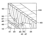
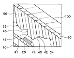
次に、日射用レンズ部42の具体的な構成について説明する。まず、図3に示されるように、日射用レンズ部42は、日射検出素子41側に突出した形状になっている。そして、図2及び図3に示されるように、日射用レンズ部42は、低仰角面43、対向面44、及び高仰角面45を有して構成されている。なお、図3の断面図は、仰角の角度方向に平行な日射用レンズ部42の断面を見た図である。図1も同じである。
低仰角面43は、仰角範囲のうちの低仰角側の光を取り込むための面である。対向面44は、低仰角面43に隣接すると共に日射検出素子41に対向する面である。図2に示されるように、対向面44は四角形状になっており、仰角特性に応じたサイズに規定されている。そして、高仰角面45は、仰角範囲のうちの高仰角側の光を取り込むための面である。
さらに、図3に示されるように、本実施形態では、日射用レンズ部42は、高仰角面45と対向面44とに隣接する反射面46を有している。この反射面46は、日射用レンズ部42に入射した光の一部を反射面46に反射させて日射検出素子41に導くための部分である。反射面46は、対向面44に対して鋭角で接続される一方、高仰角面45に対して鈍角で接続されている。これら「鋭角」及び「鈍角」は日射用レンズ部42のレンズ部分が形成する角度のことである。なお、対向面44と低仰角面43とは鈍角で接続されている。
続いて、日射用レンズ部42の反射面46の作用効果について説明する。まず、日射用レンズ部42は、低仰角面43及び高仰角面45によって日射検出素子41に対して光を導くことにより、仰角範囲のうちの所定角度に日射量のピークを持たせることになる。しかしながら、日射用レンズ部42には高仰角面45と対向面44とに隣接する反射面46が設けられている。このため、反射面46で反射した低仰角側の日射光が増加するので、日射検出素子41で検出される低仰角側の日射量のピークの範囲を広げることができる。
具体的には、図4に示されるように、日射用レンズ部42に反射面46が設けられていない場合には仰角が45°付近で日射量がピークとなる。一方、日射用レンズ部42に反射面46が設けられている場合には反射面46で反射した低仰角側の日射光が増加するので、低仰角側の日射量の相対値が上昇する。これは幅広い角度の光の入射が可能になったからである。したがって、仰角範囲のうち所定角度(例えば45°)を含む一定範囲の日射量を一定化することができる。
なお、図4では、例えば45°における日射量に対する他の角度の日射量の相対値を示している。また、図4は、車両ガラス角度が35°のフロントガラス100に統合装置1が取り付けられたときに測定された仰角特性である。
以上のように、反射面46を、仰角範囲のうち所定角度(例えば45°)を含む一定範囲の日射量を一定化するピーク調整部として機能させることができる。本実施形態では、例えば30°~60°の仰角範囲において日射量を一定の日射量を取り込むことができる。日射量が一定化された仰角範囲は、反射面46の形状や面積等に応じて適宜調整することができる。
このように、反射面46によって日射用レンズ部42の仰角特性を調整することができるので、日射センサ40を様々な傾斜角度のフロントガラス100に適用させることができる。したがって、フロントガラス100の傾斜角度によって日射センサ40の仰角特性が受ける影響を低減することができる。
また、本実施形態では、日射用レンズ部42がレインセンサ30の第1レンズ部34と第2レンズ部35との間に配置されているので、統合装置1のサイズの大型化を回避することができる。さらに、レンズ50のうちレインセンサ30として機能する部分全体を介して光を日射用レンズ部42に取り込むことができる。
なお、本実施形態のレインセンサ30は、「車載製品」を提供し得る。また、本実施形態の反射面46は、「ピーク調整部」を提供し得る。
(第2実施形態)
本実施形態では、第1実施形態と異なる部分について説明する。図5に示されるように、レンズ50は壁部47を備えている。本実施形態では、壁部47は、第1レンズ部34と日射用レンズ部42との間、及び、日射用レンズ部42と第2レンズ部35との間に設けられている。
本実施形態では、第1実施形態と異なる部分について説明する。図5に示されるように、レンズ50は壁部47を備えている。本実施形態では、壁部47は、第1レンズ部34と日射用レンズ部42との間、及び、日射用レンズ部42と第2レンズ部35との間に設けられている。
これによると、壁部47が第1レンズ部34と日射用レンズ部42との間に設けられているので、第1レンズ部34側から日射検出素子41に向かう光を遮断することができる。また、壁部47が日射用レンズ部42と第2レンズ部35との間に設けられているので、第2レンズ部35側から日射検出素子41に向かう光を遮断することができる。したがって、壁部47によって日射検出素子41に導かれる不要光が遮られるので、日射センサ40の検出精度を向上させることができる。
(第3実施形態)
本実施形態では、第1、第2実施形態と異なる部分について説明する。図6に示されるように、日射用レンズ部42の対向面44は、日射検出素子41の仰角を構成する面に沿って切断された日射用レンズ部42の断面が、日射検出素子41から離れるように凹んだ球面状となるように形成されている。
本実施形態では、第1、第2実施形態と異なる部分について説明する。図6に示されるように、日射用レンズ部42の対向面44は、日射検出素子41の仰角を構成する面に沿って切断された日射用レンズ部42の断面が、日射検出素子41から離れるように凹んだ球面状となるように形成されている。
なお、「フロントガラス100の仰角を構成する面」とは、フロントガラス100の傾斜面と水平面とを各面の接続点を含むように切断した三角状の断面のことである。言い換えると、地面に垂直であると共に車両の進行方向に沿った面である。
ここで、日射用レンズ部42の対向面44の断面形状は球面状であるが、対向面44の全体は例えば円筒状に反っている形状や椀状に反っている形状になっている。「椀状」とは、球状体の殻の一部の形状であったり、コンタクトレンズの形状を指す。
以上のように、日射用レンズ部42の対向面44の形状を調整することにより、日射量のピークの一定範囲を微調整することができる。
(第4実施形態)
本実施形態では、第3実施形態と異なる部分について説明する。図7に示されるように、日射用レンズ部42の対向面44は、日射検出素子41の仰角を構成する面に沿って切断された日射用レンズ部42の断面が、日射検出素子41側に突出した球面状となるように形成されている。そして、日射用レンズ部42の対向面44の全体は例えば円筒状に突出した形状や椀状に突出した形状になっている。これにより、第3実施形態と同様に、日射量のピークの一定範囲を微調整することができる。
本実施形態では、第3実施形態と異なる部分について説明する。図7に示されるように、日射用レンズ部42の対向面44は、日射検出素子41の仰角を構成する面に沿って切断された日射用レンズ部42の断面が、日射検出素子41側に突出した球面状となるように形成されている。そして、日射用レンズ部42の対向面44の全体は例えば円筒状に突出した形状や椀状に突出した形状になっている。これにより、第3実施形態と同様に、日射量のピークの一定範囲を微調整することができる。
(第5実施形態)
本実施形態では、第1~第3実施形態と異なる部分について説明する。上記各実施形態では、低仰角側の光を多く取り込むことで日射量のピークの範囲を広げていたが、本実施形態では高仰角側の光を取り込みにくくすることで日射量のピークの範囲を広げることが特徴となっている。
本実施形態では、第1~第3実施形態と異なる部分について説明する。上記各実施形態では、低仰角側の光を多く取り込むことで日射量のピークの範囲を広げていたが、本実施形態では高仰角側の光を取り込みにくくすることで日射量のピークの範囲を広げることが特徴となっている。
具体的には、図8に示されるように、日射用レンズ部42は、低仰角面43、対向面44、及び高仰角面45を有して構成されている。対向面44は低仰角面43及び高仰角面45の両方に隣接している。
さらに、対向面44は、凹凸部48を有している。凹凸部48は、対向面44のうち少なくとも低仰角面43側に形成された凹凸構造である。凹凸部48は、例えばプラズマ照射やUV照射等の光照射、しぼ加工等により形成されている。また、凹凸部48は、対向面44の一部が紙やすり等で擦られることで形成されていても良い。すなわち、凹凸部48は、対向面44の一部が荒らされた部分であると言える。
次に、凹凸部48の作用効果について説明する。図9に示されるように、日射用レンズ部42に凹凸部48が設けられていない場合には仰角が45°付近で日射量がピークとなる。一方、日射用レンズ部42の対向面44に凹凸部48が設けられている場合には高仰角側の日射光が凹凸部48で散乱するので、高仰角側の日射光が日射検出素子41で検出されにくくなる。
このように、凹凸部48で散乱した高仰角側の日射光が低減するので、高仰角側の相対値が低下する。これにより、日射検出素子41で検出される日射量のピークの範囲を広げることができる。以上のように、凹凸部48を、仰角範囲のうち所定角度(例えば45°)を含む一定範囲の日射量を一定化するピーク調整部として機能させることができる。
なお、本実施形態の凹凸部48は、「ピーク調整部」を提供し得る。
(他の実施形態)
上記各実施形態で示された統合装置1の構成は一例であり、上記で示した構成に限定されることなく、本開示を実現できる他の構成とすることもできる。例えば、日射センサ40が一体化される車載製品はレインセンサ30に限られず、レーザレーダ等の他の車載製品でも良い。
上記各実施形態で示された統合装置1の構成は一例であり、上記で示した構成に限定されることなく、本開示を実現できる他の構成とすることもできる。例えば、日射センサ40が一体化される車載製品はレインセンサ30に限られず、レーザレーダ等の他の車載製品でも良い。
また、導光用レンズ部33と日射用レンズ部42とは別体でも良い。この場合、例えば日射用レンズ部42が導光用レンズ部33に組み付けられても良いし、導光用レンズ部33が日射用レンズ部42に組み付けられても良い。さらに、日射検出素子41は発光素子31と受光素子32との間に配置されていなくても良い。
日射量のピークを一定化するために、第1実施形態で示された反射面46と、第5実施形態で示された凹凸部48と、の両方を日射用レンズ部42に設けても良い。また、対向面44に設けられている凹凸部48は、当該対向面44の一部だけではなく、当該対向面44の全体に設けられていても良い。この場合、対向面44のうち低仰角面43側の太陽光の散乱が大きくなると共に、高仰角面45側の太陽光の散乱が小さくなるように凹凸部48の散乱度合いが調整されていれば良い。
第2実施形態で示された壁部47は一例である。壁部47は、第1レンズ部34と日射用レンズ部42との間、及び、日射用レンズ部42と第2レンズ部35との間、のいずれか一方または両方に設けられていれば良い。
第5実施形態で示された日射用レンズ部42に対して、第1~第4実施形態で示された構成を適宜組み合わせても良い。
Claims (7)
- 車両のフロントガラス(100)に固定される車載製品(30)と、
前記フロントガラス(100)に入射する日射光を受光することにより日射量を検出する日射検出素子(41)と、前記フロントガラス(100)に所定の仰角範囲で入射する前記日射光を前記日射検出素子(41)に導くと共に、前記日射検出素子(41)に対して前記仰角範囲のうちの所定角度に前記日射量のピークを持たせる日射用レンズ部(42)と、を有し、前記車載製品(30)に一体化された日射センサ(40)と、
を備え、
前記日射用レンズ部(42)は、前記仰角範囲のうち前記所定角度を含む一定範囲の前記日射量を一定化するピーク調整部(46、48)を備えている統合装置。 - 前記日射用レンズ部(42)は、前記仰角範囲のうちの低仰角側の光を取り込むための低仰角面(43)と、前記低仰角面(43)に隣接すると共に前記日射検出素子(41)に対向する対向面(44)と、前記仰角範囲のうちの高仰角側の光を取り込むための高仰角面(45)と、を有し、
前記ピーク調整部(46)は、前記高仰角面(45)と前記対向面(44)とに隣接する反射面であり、前記日射用レンズ部(42)に入射した光の一部を前記反射面に反射させて前記日射検出素子(41)に導くようになっている請求項1に記載の統合装置。 - 前記日射用レンズ部(42)は、前記仰角範囲のうちの低仰角側の光を取り込むための低仰角面(43)と、前記低仰角面(43)に隣接すると共に前記日射検出素子(41)に対向する対向面(44)と、前記仰角範囲のうちの高仰角側の光を取り込むための高仰角面(45)と、を有し、
前記ピーク調整部(48)は、前記対向面(44)のうち少なくとも前記低仰角面(43)側に形成された凹凸部である請求項1または2に記載の統合装置。 - 前記対向面(44)は、前記日射検出素子(41)の仰角を構成する面に沿って切断された前記日射用レンズ部(42)の断面が、前記日射検出素子(41)から離れるように凹んだ球面状となるように形成されている請求項2または3に記載の統合装置。
- 前記対向面(44)は、前記日射検出素子(41)の仰角を構成する面に沿って切断された前記日射用レンズ部(42)の断面が、前記日射検出素子(41)側に突出した球面状となるように形成されている請求項2または3に記載の統合装置。
- 前記車載製品(30)は、前記フロントガラス(100)に向かって発光する発光素子(31)と、前記フロントガラス(100)で反射した光を受光する受光素子(32)と、前記発光素子(31)から発せられた光を前記フロントガラス(100)に導くと共に前記フロントガラス(100)で反射した光を前記受光素子(32)に導く導光用レンズ部(33)と、を有し、前記受光素子(32)が受光した光の強度に基づいて前記フロントガラス(100)に雨滴が付着したことを検出するレインセンサであり、
前記日射検出素子(41)は、前記発光素子(31)と前記受光素子(32)との間に配置されており、
前記日射用レンズ部(42)は、前記導光用レンズ部(33)のうち前記発光素子(31)の光を集光する第1レンズ部(34)と前記フロントガラス(100)で反射した反射光を前記受光素子(32)に集光する第2レンズ部(35)との間に配置されており、
前記日射用レンズ部(42)と前記導光用レンズ部(33)とは一体成形されている請求項1ないし5のいずれか1つに記載の統合装置。 - 前記第1レンズ部(34)と前記日射用レンズ部(42)との間、及び、前記日射用レンズ部(42)と前記第2レンズ部(35)との間、のいずれか一方または両方に壁部(47)を備えている請求項6に記載の統合装置。
Priority Applications (2)
| Application Number | Priority Date | Filing Date | Title |
|---|---|---|---|
| DE112015001404.7T DE112015001404B4 (de) | 2014-03-25 | 2015-03-24 | Integrierte Vorrichtung |
| US15/123,268 US10088354B2 (en) | 2014-03-25 | 2015-03-24 | Integrated device attached to windshield having sunlight lens portion with a peak adjustment portion |
Applications Claiming Priority (2)
| Application Number | Priority Date | Filing Date | Title |
|---|---|---|---|
| JP2014061443A JP6331550B2 (ja) | 2014-03-25 | 2014-03-25 | 統合装置 |
| JP2014-061443 | 2014-03-25 |
Publications (1)
| Publication Number | Publication Date |
|---|---|
| WO2015146152A1 true WO2015146152A1 (ja) | 2015-10-01 |
Family
ID=54194699
Family Applications (1)
| Application Number | Title | Priority Date | Filing Date |
|---|---|---|---|
| PCT/JP2015/001668 Ceased WO2015146152A1 (ja) | 2014-03-25 | 2015-03-24 | 統合装置 |
Country Status (4)
| Country | Link |
|---|---|
| US (1) | US10088354B2 (ja) |
| JP (1) | JP6331550B2 (ja) |
| DE (1) | DE112015001404B4 (ja) |
| WO (1) | WO2015146152A1 (ja) |
Cited By (1)
| Publication number | Priority date | Publication date | Assignee | Title |
|---|---|---|---|---|
| WO2024048502A1 (ja) * | 2022-09-02 | 2024-03-07 | 株式会社デンソー | レインセンサ |
Families Citing this family (5)
| Publication number | Priority date | Publication date | Assignee | Title |
|---|---|---|---|---|
| DE112016004227T5 (de) | 2015-09-17 | 2018-06-14 | Ntn Corporation | Doppelreihiges selbstausrichtendes Wälzlager |
| DE102017101655B4 (de) * | 2017-01-27 | 2024-01-25 | Bcs Automotive Interface Solutions Gmbh | Elektrooptikbaugruppe sowie Verfahren zur Detektion von Umgebungslicht |
| KR102044518B1 (ko) | 2017-06-13 | 2019-11-13 | 주식회사 아모센스 | 센서 패키지용 윈도우 커버 및 이를 구비한 센서 패키지 |
| DE102019106544B4 (de) * | 2019-03-14 | 2023-08-03 | HELLA GmbH & Co. KGaA | Messvorrichtung zur Erfassung des Umgebungslichts, Regen-Licht-Sensor zur Verwendung an einer Windschutzscheibe und Kraftfahrzeug |
| JP7528814B2 (ja) | 2021-02-17 | 2024-08-06 | 株式会社デンソー | 光センサ装置 |
Citations (3)
| Publication number | Priority date | Publication date | Assignee | Title |
|---|---|---|---|---|
| JP2009085836A (ja) * | 2007-10-01 | 2009-04-23 | Denso Corp | 照度センサ |
| JP2012183886A (ja) * | 2011-03-04 | 2012-09-27 | Denso Corp | 車両用ライト点消灯装置 |
| JP2013234875A (ja) * | 2012-05-07 | 2013-11-21 | Denso Corp | 光センサ |
Family Cites Families (9)
| Publication number | Priority date | Publication date | Assignee | Title |
|---|---|---|---|---|
| JPH0821765A (ja) | 1994-07-08 | 1996-01-23 | Nippondenso Co Ltd | 日射センサ |
| DE19861428B4 (de) | 1998-03-17 | 2008-01-10 | Robert Bosch Gmbh | Optischer Sensor |
| DE19839273A1 (de) | 1998-03-17 | 1999-09-23 | Bosch Gmbh Robert | Optischer Sensor |
| US6521882B1 (en) * | 1998-03-27 | 2003-02-18 | Denso Corporation | Optical sensor with directivity controlled |
| DE102004003686A1 (de) | 2004-01-24 | 2005-08-18 | Hella Kgaa Hueck & Co. | Vorrichtung für ein Kraftfahrzeug zum Messen von Licht |
| JP4485864B2 (ja) | 2004-07-12 | 2010-06-23 | スタンレー電気株式会社 | 雨滴センサ |
| DE102010041649A1 (de) | 2010-09-29 | 2012-03-29 | Zimmer Medizinsysteme Gmbh | Elektromedizinische Vorrichtung zum nicht-invasiven Reduzieren oder Entfernen von subkutanem Fettgewebe |
| EP2840367A1 (en) | 2012-04-18 | 2015-02-25 | Denso Corporation | Optical sensor |
| JP5940388B2 (ja) * | 2012-06-22 | 2016-06-29 | 株式会社ヴァレオジャパン | 雨滴検出装置 |
-
2014
- 2014-03-25 JP JP2014061443A patent/JP6331550B2/ja active Active
-
2015
- 2015-03-24 WO PCT/JP2015/001668 patent/WO2015146152A1/ja not_active Ceased
- 2015-03-24 US US15/123,268 patent/US10088354B2/en active Active
- 2015-03-24 DE DE112015001404.7T patent/DE112015001404B4/de active Active
Patent Citations (3)
| Publication number | Priority date | Publication date | Assignee | Title |
|---|---|---|---|---|
| JP2009085836A (ja) * | 2007-10-01 | 2009-04-23 | Denso Corp | 照度センサ |
| JP2012183886A (ja) * | 2011-03-04 | 2012-09-27 | Denso Corp | 車両用ライト点消灯装置 |
| JP2013234875A (ja) * | 2012-05-07 | 2013-11-21 | Denso Corp | 光センサ |
Cited By (1)
| Publication number | Priority date | Publication date | Assignee | Title |
|---|---|---|---|---|
| WO2024048502A1 (ja) * | 2022-09-02 | 2024-03-07 | 株式会社デンソー | レインセンサ |
Also Published As
| Publication number | Publication date |
|---|---|
| DE112015001404T5 (de) | 2016-12-22 |
| JP6331550B2 (ja) | 2018-05-30 |
| JP2015184154A (ja) | 2015-10-22 |
| US10088354B2 (en) | 2018-10-02 |
| US20170067776A1 (en) | 2017-03-09 |
| DE112015001404B4 (de) | 2022-12-01 |
Similar Documents
| Publication | Publication Date | Title |
|---|---|---|
| JP6331550B2 (ja) | 統合装置 | |
| US6507015B1 (en) | Raindrop sensor having plano-convex lens | |
| CN102472840B (zh) | 用于同时聚焦到两个视野范围的光学模块 | |
| CN101566695B (zh) | 光学传感器件 | |
| KR100638299B1 (ko) | 빗방울 센서 | |
| CN1135589C (zh) | 具有高效率的高斜度光学系统的小型湿度检测器 | |
| US7847255B2 (en) | Multi-mode rain sensor | |
| US6018165A (en) | Optoelectronic sensor device | |
| JP5459273B2 (ja) | 雨滴検出装置 | |
| JP6094354B2 (ja) | 雨滴検出装置 | |
| US12152932B2 (en) | Optical sensor device | |
| CN110073201A (zh) | 集成的雨和太阳辐射传感模块 | |
| JP4973692B2 (ja) | 移動体用光センサ装置 | |
| JP4637907B2 (ja) | 自動車用光電式センサー装置 | |
| WO2014181506A1 (ja) | 水滴検出センサ | |
| US8389966B2 (en) | Ambient light detecting device for a vehicle | |
| US20160339873A1 (en) | Illumination for Detecting Raindrops on a Pane by Means of a Camera | |
| US20140196525A1 (en) | Sensor device for detecting moisture on a pane | |
| US20060054701A1 (en) | Object detecting apparatus having hydrophilic light radiating window | |
| JP2021056064A (ja) | 液滴センサ | |
| EP3604050B1 (en) | Optical moisture sensor for automotive applications | |
| WO2024048502A1 (ja) | レインセンサ | |
| WO2023110694A1 (en) | Detection device for a vehicle |
Legal Events
| Date | Code | Title | Description |
|---|---|---|---|
| 121 | Ep: the epo has been informed by wipo that ep was designated in this application |
Ref document number: 15768091 Country of ref document: EP Kind code of ref document: A1 |
|
| WWE | Wipo information: entry into national phase |
Ref document number: 15123268 Country of ref document: US |
|
| WWE | Wipo information: entry into national phase |
Ref document number: 112015001404 Country of ref document: DE |
|
| 122 | Ep: pct application non-entry in european phase |
Ref document number: 15768091 Country of ref document: EP Kind code of ref document: A1 |